EP4574492A2 - Improved support system for a vehicular battery - Google Patents
Improved support system for a vehicular battery Download PDFInfo
- Publication number
- EP4574492A2 EP4574492A2 EP24217670.9A EP24217670A EP4574492A2 EP 4574492 A2 EP4574492 A2 EP 4574492A2 EP 24217670 A EP24217670 A EP 24217670A EP 4574492 A2 EP4574492 A2 EP 4574492A2
- Authority
- EP
- European Patent Office
- Prior art keywords
- battery pack
- assembly according
- vehicle assembly
- housing
- bottom wall
- Prior art date
- Legal status (The legal status is an assumption and is not a legal conclusion. Google has not performed a legal analysis and makes no representation as to the accuracy of the status listed.)
- Pending
Links
Images


Classifications
-
- B—PERFORMING OPERATIONS; TRANSPORTING
- B60—VEHICLES IN GENERAL
- B60K—ARRANGEMENT OR MOUNTING OF PROPULSION UNITS OR OF TRANSMISSIONS IN VEHICLES; ARRANGEMENT OR MOUNTING OF PLURAL DIVERSE PRIME-MOVERS IN VEHICLES; AUXILIARY DRIVES FOR VEHICLES; INSTRUMENTATION OR DASHBOARDS FOR VEHICLES; ARRANGEMENTS IN CONNECTION WITH COOLING, AIR INTAKE, GAS EXHAUST OR FUEL SUPPLY OF PROPULSION UNITS IN VEHICLES
- B60K1/00—Arrangement or mounting of electrical propulsion units
- B60K1/04—Arrangement or mounting of electrical propulsion units of the electric storage means for propulsion
-
- H—ELECTRICITY
- H01—ELECTRIC ELEMENTS
- H01M—PROCESSES OR MEANS, e.g. BATTERIES, FOR THE DIRECT CONVERSION OF CHEMICAL ENERGY INTO ELECTRICAL ENERGY
- H01M50/00—Constructional details or processes of manufacture of the non-active parts of electrochemical cells other than fuel cells, e.g. hybrid cells
- H01M50/20—Mountings; Secondary casings or frames; Racks, modules or packs; Suspension devices; Shock absorbers; Transport or carrying devices; Holders
- H01M50/244—Secondary casings; Racks; Suspension devices; Carrying devices; Holders characterised by their mounting method
-
- H—ELECTRICITY
- H01—ELECTRIC ELEMENTS
- H01M—PROCESSES OR MEANS, e.g. BATTERIES, FOR THE DIRECT CONVERSION OF CHEMICAL ENERGY INTO ELECTRICAL ENERGY
- H01M50/00—Constructional details or processes of manufacture of the non-active parts of electrochemical cells other than fuel cells, e.g. hybrid cells
- H01M50/20—Mountings; Secondary casings or frames; Racks, modules or packs; Suspension devices; Shock absorbers; Transport or carrying devices; Holders
- H01M50/249—Mountings; Secondary casings or frames; Racks, modules or packs; Suspension devices; Shock absorbers; Transport or carrying devices; Holders specially adapted for aircraft or vehicles, e.g. cars or trains
-
- H—ELECTRICITY
- H01—ELECTRIC ELEMENTS
- H01M—PROCESSES OR MEANS, e.g. BATTERIES, FOR THE DIRECT CONVERSION OF CHEMICAL ENERGY INTO ELECTRICAL ENERGY
- H01M50/00—Constructional details or processes of manufacture of the non-active parts of electrochemical cells other than fuel cells, e.g. hybrid cells
- H01M50/20—Mountings; Secondary casings or frames; Racks, modules or packs; Suspension devices; Shock absorbers; Transport or carrying devices; Holders
- H01M50/262—Mountings; Secondary casings or frames; Racks, modules or packs; Suspension devices; Shock absorbers; Transport or carrying devices; Holders with fastening means, e.g. locks
-
- B—PERFORMING OPERATIONS; TRANSPORTING
- B60—VEHICLES IN GENERAL
- B60K—ARRANGEMENT OR MOUNTING OF PROPULSION UNITS OR OF TRANSMISSIONS IN VEHICLES; ARRANGEMENT OR MOUNTING OF PLURAL DIVERSE PRIME-MOVERS IN VEHICLES; AUXILIARY DRIVES FOR VEHICLES; INSTRUMENTATION OR DASHBOARDS FOR VEHICLES; ARRANGEMENTS IN CONNECTION WITH COOLING, AIR INTAKE, GAS EXHAUST OR FUEL SUPPLY OF PROPULSION UNITS IN VEHICLES
- B60K1/00—Arrangement or mounting of electrical propulsion units
- B60K1/04—Arrangement or mounting of electrical propulsion units of the electric storage means for propulsion
- B60K2001/0405—Arrangement or mounting of electrical propulsion units of the electric storage means for propulsion characterised by their position
- B60K2001/0411—Arrangement in the front part of the vehicle
-
- B—PERFORMING OPERATIONS; TRANSPORTING
- B60—VEHICLES IN GENERAL
- B60K—ARRANGEMENT OR MOUNTING OF PROPULSION UNITS OR OF TRANSMISSIONS IN VEHICLES; ARRANGEMENT OR MOUNTING OF PLURAL DIVERSE PRIME-MOVERS IN VEHICLES; AUXILIARY DRIVES FOR VEHICLES; INSTRUMENTATION OR DASHBOARDS FOR VEHICLES; ARRANGEMENTS IN CONNECTION WITH COOLING, AIR INTAKE, GAS EXHAUST OR FUEL SUPPLY OF PROPULSION UNITS IN VEHICLES
- B60K1/00—Arrangement or mounting of electrical propulsion units
- B60K1/04—Arrangement or mounting of electrical propulsion units of the electric storage means for propulsion
- B60K2001/0405—Arrangement or mounting of electrical propulsion units of the electric storage means for propulsion characterised by their position
- B60K2001/0422—Arrangement under the front seats
-
- H—ELECTRICITY
- H01—ELECTRIC ELEMENTS
- H01M—PROCESSES OR MEANS, e.g. BATTERIES, FOR THE DIRECT CONVERSION OF CHEMICAL ENERGY INTO ELECTRICAL ENERGY
- H01M2220/00—Batteries for particular applications
- H01M2220/20—Batteries in motive systems, e.g. vehicle, ship, plane
-
- Y—GENERAL TAGGING OF NEW TECHNOLOGICAL DEVELOPMENTS; GENERAL TAGGING OF CROSS-SECTIONAL TECHNOLOGIES SPANNING OVER SEVERAL SECTIONS OF THE IPC; TECHNICAL SUBJECTS COVERED BY FORMER USPC CROSS-REFERENCE ART COLLECTIONS [XRACs] AND DIGESTS
- Y02—TECHNOLOGIES OR APPLICATIONS FOR MITIGATION OR ADAPTATION AGAINST CLIMATE CHANGE
- Y02E—REDUCTION OF GREENHOUSE GAS [GHG] EMISSIONS, RELATED TO ENERGY GENERATION, TRANSMISSION OR DISTRIBUTION
- Y02E60/00—Enabling technologies; Technologies with a potential or indirect contribution to GHG emissions mitigation
- Y02E60/10—Energy storage using batteries
Definitions
- the present invention relates to a support system for an electric battery.
- the present invention has its preferred, although not exclusive, application in the support of a vehicular battery. Reference will be made to this application below by way of an example.
- the vehicle 1 defines a housing 2 delimited by a pair of axial walls 3 along a longitudinal axis A of the vehicle, a bottom wall 4 and an upper wall 5 spaced along a vertical axis C perpendicular to the axis A.
- the housing 2 In a direction along a transverse axis B, perpendicular to the axes A, B, the housing 2 is delimited by an inner wall (not visible) and selectively opened externally, for example by means of a hatch (not shown).
- the housing 2 is configured to house a battery pack 6, for example comprising a single vehicular battery or several vehicular batteries, configured to be electrically connected to operating systems of the vehicle 1 configured to allow its operation and/or traction.
- a battery pack 6 for example comprising a single vehicular battery or several vehicular batteries, configured to be electrically connected to operating systems of the vehicle 1 configured to allow its operation and/or traction.
- the battery pack 6 is opportunely fixed to one of the walls of the housing 2 by means of a support system 7 configured to prevent movement of the battery pack along the aforementioned longitudinal, transverse and vertical axes A, B, C.
- the support system 7 comprises first blocking means 8 configured to prevent movement of the battery pack 6 by coupling a portion thereof to the aforesaid wall of the housing 2.
- the battery pack 6 is supported by a plate 11 described in more detail below, housed in the housing 2 and operatively interposed between the battery pack 6 and the bottom wall 4.
- the battery pack 6 comprises a base portion 6" cooperating in contact with the bottom wall 4 and extending further with respect to one of the aforesaid longitudinal, transverse and vertical axes A, B, C with respect to the remaining portion of the battery pack 6.
- said base portion 6" extends further with respect to the remaining battery portion 6 with respect to the longitudinal and transverse axes A, C.
- the battery pack 6 has a substantially parallelepiped shape and therefore comprises a pair of side walls 6a distanced along the transverse axis C and a pair of axial walls 6b distanced along the longitudinal axis A.
- the shaped plate 12 may also comprise at least one rib 12′′′ connecting to each other the main portion and the coupling portion 12'', so as to increase their robustness.
- the shaped plate 12 is made of a single piece and, even more in particular, of a polymeric/plastic material.
- connection means 13 such as threaded means, like a bolt.
- the base portion 6" may be provided, at the coupling portion 12", with a corrugated profile 6′′′ and equally the coupling portion 12" may be provided with a corresponding profile, so as to increase the coupling surface between the coupling portion 12" and the base portion 6" , making the coupling of the battery 6 to the housing 2 firmer.
- the plate 11 comprises a flat portion 11' sized so as to house the entire battery pack 6, so that the base portion 6' thereof is entirely supported by it.
- the flat portion is fixed to the bottom wall 4 by means of a plurality of connection means 13, such as the above type.
- the flat portion 11' defines a hole for inserting the aforesaid connection means 13 and, in particular, defines a support portion 11′′′, raised with respect to the flat portion 11', configured to support in contact the shaped plate 12.
- the support system 7 further comprises, or in combination with the previous blocking means 8, second blocking means 9 configured to prevent the movement of the battery pack 6 cooperating in contact between a portion of it with a wall of the housing 2.
- first and second blocking means 8, 9 are present, the second blocking means 9 cooperate in contact with a different wall of the housing 2, in particular transverse, with respect to the wall on which the first blocking means 8 are fixed.
- the second blocking means 9 comprise a pad 14 operatively interposed in contact between the battery 6 and one of the walls of the housing 2.
- the pad 14 ( Figure 4 ) is shaped so as to adapt to the shape of the axial walls 6b and the axial walls 3, so as to prevent clearance between the battery 6 and the housing 2 through interposition between them.
- the pad 14 may be sized to be housed with preload between the battery 6 and the housing 2.
- the pad 14 is carried by the cantilevered portion 11" of the plate 11, in particular, the pad 14 defines a main portion 14' and an appendix 14'' extending from the main portion 14" and separated from the main portion by a groove 17.
- the groove 17 is sized so as to house inside it the cantilevered portion 11'' of the plate 11.
- the appendix 14'' extends along the vertical axis C minus the main portion 14', so that, when the pad 14 is housed on the cantilevered portion 11", the thickness of the flat portion 11" is compensated.
- the geometrical adaptations between the shaped plate 12 and the pad 14 and the housing 2 (and/or the plate 11) and the battery 6 further allow a firmer connection of the battery 6 in the housing 2.
- connection means 13 or retention means 15 allows reduction of the assembly times of the battery and its maintenance, allowing easy access for assembly/disassembly of them.
- the combined action of the first and second blocking means acts synergically to reinforce the fixing of the battery, preventing its undesired movements in any driving or test conditions.
- the shape and arrangement of the battery and the housing 2 and consequently the shape and positioning of the plate 11 and of the first and second blocking means may vary.
- first and second blocking means may vary, as may their material and their fixing in the housing 2.
Landscapes
- Chemical & Material Sciences (AREA)
- Chemical Kinetics & Catalysis (AREA)
- Electrochemistry (AREA)
- General Chemical & Material Sciences (AREA)
- Engineering & Computer Science (AREA)
- Aviation & Aerospace Engineering (AREA)
- Combustion & Propulsion (AREA)
- Transportation (AREA)
- Mechanical Engineering (AREA)
- Battery Mounting, Suspending (AREA)
Abstract
the battery pack (6) comprising a base portion (6') and at least one wall (6a, 6b) defined by a portion of the battery pack (6) extending from the base portion (6'),
the fixing system (7) comprising first and/or second blocking means (8, 9) configured to make the battery pack (6) integral in the housing (2).
Description
- This patent application claims priority from
Italian patent application no. 102023000026658 filed on December 14, 2023 - The present invention relates to a support system for an electric battery.
- The present invention has its preferred, although not exclusive, application in the support of a vehicular battery. Reference will be made to this application below by way of an example.
- There continues to be a need to electrify vehicles in order to reduce the emissions of pollutants, by supplying hybrid or electric vehicles.
- For this purpose, it is necessary to provide electric batteries configured to store electric energy and to exchange it with electric machines to allow them to operate as a motor or generator.
- These electric batteries are normally housed in vehicle compartments configured to maintain the electric batteries isolated from the external environment, so as not to be contaminated by external agents and so as to avoid the leakage of hazardous liquids from the batteries themselves.
- It is therefore necessary to provide adequate support to these vehicular batteries in a manner to avoid their movement both during travel of the vehicle and during pre-established stresses, such as homologation or safety tests.
- The known fixing systems are not sufficiently robust to fix the vehicular batteries in the aforesaid compartments.
- For this purpose, it is known to fix the vehicular batteries by means of strap systems, so as to prevent any movement of them in the compartment.
- However, these compartments are usually made in difficult to reach positions and therefore make it difficult to mount these strap systems around the battery system both during manufacturing and during maintenance of the vehicle.
- There is therefore a need to provide support systems for vehicular batteries that are simultaneously efficient in fixing a vehicular battery in its compartment and economical and easy to mount.
- The object of the present invention is therefore to satisfy the needs indicated here above, in an optimal and economical manner.
- The aforesaid object is achieved by a vehicle assembly as claimed in the attached claims, which form an integral part of the present description.
- For a better understanding of the present invention, a preferred embodiment is described below, by way of nonlimiting example, with reference to the appended drawings, in which:
-
Figure 1 is a perspective view of a portion of a vehicle comprising a battery fixed by means of a support system according to the invention; -
Figure 2 is a perspective view of a battery assembly comprising a support system according to the invention; -
Figure 3 is a perspective view of a support system according to the invention; -
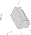
Figure 4 is a perspective view of an element of the support system according to the invention. -
Figure 1 shows a portion of a vehicle 1, such as an LVC (Light Commercial Vehicle). In particular, said portion is a front portion of the vehicle 1 corresponding with the support platform of the driver's seat. - In detail, the vehicle 1 defines a
housing 2 delimited by a pair ofaxial walls 3 along a longitudinal axis A of the vehicle, a bottom wall 4 and anupper wall 5 spaced along a vertical axis C perpendicular to the axis A. - In a direction along a transverse axis B, perpendicular to the axes A, B, the
housing 2 is delimited by an inner wall (not visible) and selectively opened externally, for example by means of a hatch (not shown). - The
housing 2 is configured to house abattery pack 6, for example comprising a single vehicular battery or several vehicular batteries, configured to be electrically connected to operating systems of the vehicle 1 configured to allow its operation and/or traction. - The
battery pack 6 is opportunely fixed to one of the walls of thehousing 2 by means of asupport system 7 configured to prevent movement of the battery pack along the aforementioned longitudinal, transverse and vertical axes A, B, C. - In detail, the
support system 7 comprises first blocking means 8 configured to prevent movement of thebattery pack 6 by coupling a portion thereof to the aforesaid wall of thehousing 2. - For the sake of simplicity, reference will be made below to an illustrated embodiment, in which the
battery pack 6 is supported by the bottom wall 4 and spaced from theupper wall 5 and from theaxial walls 3. - Advantageously, the
battery pack 6 is supported by aplate 11 described in more detail below, housed in thehousing 2 and operatively interposed between thebattery pack 6 and the bottom wall 4. - In further detail, the
battery pack 6 comprises abase portion 6" cooperating in contact with the bottom wall 4 and extending further with respect to one of the aforesaid longitudinal, transverse and vertical axes A, B, C with respect to the remaining portion of thebattery pack 6. - In the embodiment described, said
base portion 6" extends further with respect to theremaining battery portion 6 with respect to the longitudinal and transverse axes A, C. - In particular, in the embodiment described, the
battery pack 6 has a substantially parallelepiped shape and therefore comprises a pair ofside walls 6a distanced along the transverse axis C and a pair ofaxial walls 6b distanced along the longitudinal axis A. - The first blocking means 8 comprise essentially a
shaped plate 12 configured to be fixed to the bottom wall 4 and configured to cooperate in contact with thebase portion 6" of thebattery 6 to maintain it fixed to the bottom wall 4. - In detail, the
shaped plate 12 comprises a main portion 12' and a coupling portion 12'' extending from the main portion 12', in particular cantilevered from it with respect to a longitudinal axis thereof. - The
shaped plate 12 may also comprise at least onerib 12‴ connecting to each other the main portion and the coupling portion 12'', so as to increase their robustness. - Advantageously, the
shaped plate 12 is made of a single piece and, even more in particular, of a polymeric/plastic material. - The
shaped plate 12 is advantageously fixed to the bottom wall 4 by means of connection means 13, such as threaded means, like a bolt. - Furthermore, the
base portion 6" may be provided, at thecoupling portion 12", with acorrugated profile 6‴ and equally thecoupling portion 12" may be provided with a corresponding profile, so as to increase the coupling surface between thecoupling portion 12" and thebase portion 6" , making the coupling of thebattery 6 to thehousing 2 firmer. - As emerges more clearly from
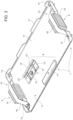
Figure 3 , theplate 11 comprises a flat portion 11' sized so as to house theentire battery pack 6, so that the base portion 6' thereof is entirely supported by it. - The flat portion is fixed to the bottom wall 4 by means of a plurality of connection means 13, such as the above type.
- In further detail, the
plate 11 comprises acantilevered portion 11" extending along the vertical axis C on at least part of the perimeter of the flat portion 11', so as to define an edge, at least discontinuous, of containment. In particular, said cantileveredportion 11‴, as shown, may comprise profiles of variable extension along the vertical axis C. - At the fixing of the
shaped plate 12, the flat portion 11' defines a hole for inserting the aforesaid connection means 13 and, in particular, defines asupport portion 11‴, raised with respect to the flat portion 11', configured to support in contact theshaped plate 12. - The
support system 7 further comprises, or in combination with the previous blocking means 8, second blocking means 9 configured to prevent the movement of thebattery pack 6 cooperating in contact between a portion of it with a wall of thehousing 2. - In particular, if first and second blocking means 8, 9 are present, the second blocking means 9 cooperate in contact with a different wall of the
housing 2, in particular transverse, with respect to the wall on which the first blocking means 8 are fixed. - In detail, the second blocking means 9 comprise a
pad 14 operatively interposed in contact between thebattery 6 and one of the walls of thehousing 2. - In the embodiment described, reference will be made to the
axial walls 6b and to theaxial walls 3 of thehousing 2 for convenience. - The pad 14 (
Figure 4 ) is shaped so as to adapt to the shape of theaxial walls 6b and theaxial walls 3, so as to prevent clearance between thebattery 6 and thehousing 2 through interposition between them. - In detail, the
pad 14 may be sized to be housed with preload between thebattery 6 and thehousing 2. - Advantageously, the
pad 14 is carried by thecantilevered portion 11" of theplate 11, in particular, thepad 14 defines a main portion 14' and an appendix 14'' extending from themain portion 14" and separated from the main portion by agroove 17. - The
groove 17 is sized so as to house inside it the cantilevered portion 11'' of theplate 11. In particular, the appendix 14'' extends along the vertical axis C minus the main portion 14', so that, when thepad 14 is housed on thecantilevered portion 11", the thickness of theflat portion 11" is compensated. - In particular, according to what is described above, the appendix 14'' cooperates in contact with the
battery 6 while the main portion 14' cooperates in contact with theaxial wall 3. - Advantageously, the
pad 14 is made of a single piece and of a polymeric/plastic material. - The
pad 14 is further fixed to the bottom wall 4 by means of retention means 15 configured, in particular, to compensate a movement along the vertical axis C of thepad 14. - In detail, such retention means 15 comprise a
strap 16 fixed at its ends by means of connection means 13. - Advantageously, the retention means 15 are fixed by means of said connection means 13 that connect the
plate 11 to the bottom wall 4. - As visible in the figures, two second blocking means 9 are present and configured to cooperate with two
opposite walls 6b of thebattery pack 6 and respective axial walls 4 of thehousing 2. - Equally, several first blocking means 8 could be provided on the same edge of the base portion 6' of the
battery pack 6 or on the opposite edges of it. - Operation of the embodiment of the vehicle assembly according to the invention described above is as follows.
- Once the
plate 11 is fixed, thebattery 6 may be housed on it and fixed by means of the first and/or second blocking means 8 and 9, which compensate any forces and/or torques acting along the three longitudinal, transverse and vertical axes A, B, C. - The benefits of the vehicle assembly according to the invention are clear from the above.
- Thanks to the fixing system provided, it is possible to compensate forces and/or torques acting along the three longitudinal, transverse and vertical axes A, B, C acting between the
battery 6 and thehousing 2, preventing its detachment from thehousing 2. - The possibility of damage to the
battery 6 and leakage of toxic liquids is consequently reduced. - Furthermore, a firm fixing of the
battery 6 reduces its movements and therefore safeguards its electrical connections with other operating elements of the vehicle. - Manufacture of the blocking means as elements in a single polymeric/plastic piece makes them particularly economical.
- The geometrical adaptations between the
shaped plate 12 and thepad 14 and the housing 2 (and/or the plate 11) and thebattery 6 further allow a firmer connection of thebattery 6 in thehousing 2. - Furthermore, fixing of the blocking means in the housing, by means of connection means 13 or retention means 15, allows reduction of the assembly times of the battery and its maintenance, allowing easy access for assembly/disassembly of them.
- In particular, the combined action of the first and second blocking means acts synergically to reinforce the fixing of the battery, preventing its undesired movements in any driving or test conditions.
- In conclusion, it is clear that changes and variants can be made to the vehicle assembly according to the present invention without thus deviating from the scope of protection as defined by the claims.
- Clearly, the shape and arrangement of the battery and the
housing 2 and consequently the shape and positioning of theplate 11 and of the first and second blocking means may vary. - Similarly, the number and the shape of the first and second blocking means may vary, as may their material and their fixing in the
housing 2.
Claims (17)
- Vehicle assembly comprising a battery pack (6) and a fixing system (7) for fixing said battery pack (6) in a housing (2) of a vehicle (1),said housing (2) extending along a longitudinal axis (A), a transverse axis (C) and a vertical axis (B) perpendicular to each other and being defined at least by a first pair of walls (3) and a bottom wall (4)said battery pack (6) comprising a base portion (6') and at least one wall (6a, 6b) defined by a portion of said battery pack (6) extending from said base portion (6'),said fixing assembly (7) comprising- first blocking means (8) configured to be fixed to said bottom wall (4) and to cooperate in contact with said base portion (6') to prevent the movement of said battery along at least one of said longitudinal, transverse and/or vertical axes (A, B, C).- second blocking means (9) configured to be operatively interposed to cooperate in contact with said battery pack (6) and one of said first walls (3) to prevent the movement of said battery along at least one of said longitudinal, transverse and/or vertical axes (A, B, C).
- Vehicle assembly according to claim 1, wherein said first blocking means (8) comprise a shaped plate (12) comprising a flat portion (12') which can be fixed by means of connection means (13) to said bottom wall (4) and a coupling portion (12'') extending from said flat portion (12') and configured to cooperate in contact with said base portion (6').
- Vehicle assembly according to claim 2, wherein said shaped plate (12) includes at least one rib (12‴) extending between said flat portion (12') and said coupling portion (12).
- Vehicle assembly according to claim 2 or 3, wherein said shaped plate (12) is made of a single piece.
- Vehicle assembly according to claim 2, 3 or 4, wherein said shaped plate (12) is made of polymeric/plastic material.
- Vehicle assembly according to one of claims 2 to 5, wherein said base portion (6') defines a corrugated profile (6"), said coupling portion (12'') being shaped to correspond to said corrugated profile (6‴).
- Vehicle assembly according to one of the previous claims, further comprising a plate (11) operatively interposed between said battery pack (6), said bottom wall (4) and said first blocking means (8).
- Vehicle assembly according to one of the previous claims, wherein said second blocking means (9) comprise a pad (14) operatively interposed in contact between said battery pack (6) and one of said pair of walls (3) of said housing (2).
- Vehicle assembly according to one of the previous claims, wherein said pad (14) comprises a main portion (14') and an appendix (14'') extending from said main portion (14') and separated by a groove (17), said groove (17) being configured to house a cantilevered portion (11'') integral with said bottom wall (4).
- Vehicle assembly according to claim 9, when dependent on claim 7, wherein said cantilevered portion (11'') is part of said plate (11), said plate (11) comprising a flat portion (11) and said cantilevered portion (11'') extending over at least part of the perimeter of said flat portion (11).
- Vehicle assembly according to one of claims 8 to 10, wherein said pad (14) is fixed to said bottom wall (4) via retention means (15).
- Vehicle assembly according to claim 11, wherein said retention means (15) comprise a strap (16).
- Vehicle assembly according to claim 11 or 12, when dependent on claim 11, wherein said retention means (15) are connected to said bottom wall (4) via connection means (13) further configured to connect said flat portion (11') to said bottom wall (4).
- Vehicle assembly according to one of claims 8 to 13, wherein said pad (14) is made of a single piece.
- Vehicle assembly according to one of claims 8 to 14, wherein said pad (14) is made of polymeric/plastic material.
- Vehicle assembly comprising a battery pack (6) and a fixing system (7) for fixing said battery pack (6) in a housing (2) of a vehicle (1),said housing (2) extending along a longitudinal axis (A), a transverse axis (C) and a vertical axis (B) perpendicular to each other and being defined at least by a first pair of walls (3) and a bottom wall (4)said battery pack (6) comprising a base portion (6') and at least one wall (6a, 6b) defined by a portion of said battery pack (6) extending from said base portion (6'),said fixing assembly (7) comprising second blocking means (8) configured to be operatively interposed to cooperate in contact between said battery pack (6) and one of said first walls (3) to prevent the movement of said battery along at least one of said longitudinal, transverse and/or vertical axes (A, B, C).
- Vehicle (1) defining a housing (2) suitable for housing a vehicle assembly according to one of the previous claims.
Applications Claiming Priority (1)
| Application Number | Priority Date | Filing Date | Title |
|---|---|---|---|
| IT102023000026658A IT202300026658A1 (en) | 2023-12-14 | 2023-12-14 | IMPROVED VEHICLE BATTERY SUPPORT SYSTEM |
Publications (2)
| Publication Number | Publication Date |
|---|---|
| EP4574492A2 true EP4574492A2 (en) | 2025-06-25 |
| EP4574492A3 EP4574492A3 (en) | 2025-08-13 |
Family
ID=89897318
Family Applications (1)
| Application Number | Title | Priority Date | Filing Date |
|---|---|---|---|
| EP24217670.9A Pending EP4574492A3 (en) | 2023-12-14 | 2024-12-05 | Improved support system for a vehicular battery |
Country Status (2)
| Country | Link |
|---|---|
| EP (1) | EP4574492A3 (en) |
| IT (1) | IT202300026658A1 (en) |
Family Cites Families (8)
| Publication number | Priority date | Publication date | Assignee | Title |
|---|---|---|---|---|
| JPS5784223A (en) * | 1980-11-13 | 1982-05-26 | Nissan Motor Co Ltd | Vibration absorber of vehicle |
| JPS6189145A (en) * | 1984-10-05 | 1986-05-07 | Honda Motor Co Ltd | motorcycle |
| JP3683307B2 (en) * | 1995-06-30 | 2005-08-17 | ヤマハ発動機株式会社 | Battery storage device for vehicle |
| FR2883533B1 (en) * | 2005-03-24 | 2008-10-10 | Peugeot Citroen Automobiles Sa | BATTERY STACKING DEVICE COMPRISING A BASE AND A FLANGE |
| JP2009161138A (en) * | 2008-01-10 | 2009-07-23 | Yamaha Motor Co Ltd | Motorcycle power supply support mechanism and motorcycle equipped with the same |
| DE102009031779A1 (en) * | 2009-07-06 | 2011-01-13 | GM Global Technology Operations, Inc., Detroit | Floor structure for a motor vehicle |
| DE102013205637A1 (en) * | 2013-03-28 | 2014-10-02 | Jungheinrich Aktiengesellschaft | The battery holder |
| JP6507978B2 (en) * | 2015-10-06 | 2019-05-08 | トヨタ自動車株式会社 | Battery pack fixing structure |
-
2023
- 2023-12-14 IT IT102023000026658A patent/IT202300026658A1/en unknown
-
2024
- 2024-12-05 EP EP24217670.9A patent/EP4574492A3/en active Pending
Also Published As
| Publication number | Publication date |
|---|---|
| IT202300026658A1 (en) | 2025-06-14 |
| EP4574492A3 (en) | 2025-08-13 |
Similar Documents
| Publication | Publication Date | Title |
|---|---|---|
| US11780336B2 (en) | Battery assembly | |
| EP3412486B1 (en) | Battery mounting structure | |
| KR101942653B1 (en) | Battery housing of a traction battery of a motor vehicle | |
| EP2528134B1 (en) | Battery case for vehicle | |
| KR101319116B1 (en) | Battery pack | |
| EP3185336B1 (en) | On-board battery pack | |
| US9365165B2 (en) | Onboard equipment fixing structure | |
| US8950537B2 (en) | Battery system for vehicle | |
| CN117002412A (en) | vehicle | |
| JP5375079B2 (en) | Battery case for electric vehicles | |
| GB2555826B (en) | Battery support arrangement | |
| CN103796877A (en) | Protection structure for vehicle-mounted device | |
| CN101548412A (en) | Battery case for electric automobile | |
| WO2017109870A1 (en) | Mounting structure for high-voltage control device unit | |
| US20130299257A1 (en) | Battery housing | |
| US11539097B2 (en) | Battery housing for a high-voltage battery of a motor vehicle, high- voltage battery and motor vehicle | |
| CN112519894A (en) | Vehicle lower structure | |
| EP3498511B1 (en) | Method for converting a vehicle with an internal combustion engine into an electrical vehicle | |
| JP2018197079A (en) | Automotive battery pack | |
| EP3641007A1 (en) | Power storage unit and power storage device | |
| JP5212085B2 (en) | Battery case for electric vehicles | |
| CN113895247A (en) | Traction battery system for motor vehicle and motor vehicle with electric drive | |
| EP4632908A1 (en) | Improved battery pack arrangement for a vehicle | |
| JP7831706B2 (en) | Battery pack tray and battery pack equipped with this tray | |
| US11063272B2 (en) | Support frame for fuel cell and vehicle |
Legal Events
| Date | Code | Title | Description |
|---|---|---|---|
| PUAI | Public reference made under article 153(3) epc to a published international application that has entered the european phase |
Free format text: ORIGINAL CODE: 0009012 |
|
| STAA | Information on the status of an ep patent application or granted ep patent |
Free format text: STATUS: THE APPLICATION HAS BEEN PUBLISHED |
|
| AK | Designated contracting states |
Kind code of ref document: A2 Designated state(s): AL AT BE BG CH CY CZ DE DK EE ES FI FR GB GR HR HU IE IS IT LI LT LU LV MC ME MK MT NL NO PL PT RO RS SE SI SK SM TR |
|
| PUAL | Search report despatched |
Free format text: ORIGINAL CODE: 0009013 |
|
| AK | Designated contracting states |
Kind code of ref document: A3 Designated state(s): AL AT BE BG CH CY CZ DE DK EE ES FI FR GB GR HR HU IE IS IT LI LT LU LV MC ME MK MT NL NO PL PT RO RS SE SI SK SM TR |
|
| RIC1 | Information provided on ipc code assigned before grant |
Ipc: B60K 1/04 20190101AFI20250710BHEP Ipc: H01M 50/244 20210101ALI20250710BHEP Ipc: H01M 50/249 20210101ALI20250710BHEP |
|
| STAA | Information on the status of an ep patent application or granted ep patent |
Free format text: STATUS: REQUEST FOR EXAMINATION WAS MADE |
|
| 17P | Request for examination filed |
Effective date: 20260213 |