EP4574476A1 - A manifold - Google Patents
A manifold Download PDFInfo
- Publication number
- EP4574476A1 EP4574476A1 EP23218958.9A EP23218958A EP4574476A1 EP 4574476 A1 EP4574476 A1 EP 4574476A1 EP 23218958 A EP23218958 A EP 23218958A EP 4574476 A1 EP4574476 A1 EP 4574476A1
- Authority
- EP
- European Patent Office
- Prior art keywords
- manifold
- cover
- section
- expansion device
- fluid
- Prior art date
- Legal status (The legal status is an assumption and is not a legal conclusion. Google has not performed a legal analysis and makes no representation as to the accuracy of the status listed.)
- Pending
Links
Images



Classifications
-
- F—MECHANICAL ENGINEERING; LIGHTING; HEATING; WEAPONS; BLASTING
- F28—HEAT EXCHANGE IN GENERAL
- F28F—DETAILS OF HEAT-EXCHANGE AND HEAT-TRANSFER APPARATUS, OF GENERAL APPLICATION
- F28F9/00—Casings; Header boxes; Auxiliary supports for elements; Auxiliary members within casings
- F28F9/02—Header boxes; End plates
-
- F—MECHANICAL ENGINEERING; LIGHTING; HEATING; WEAPONS; BLASTING
- F25—REFRIGERATION OR COOLING; COMBINED HEATING AND REFRIGERATION SYSTEMS; HEAT PUMP SYSTEMS; MANUFACTURE OR STORAGE OF ICE; LIQUEFACTION SOLIDIFICATION OF GASES
- F25B—REFRIGERATION MACHINES, PLANTS OR SYSTEMS; COMBINED HEATING AND REFRIGERATION SYSTEMS; HEAT PUMP SYSTEMS
- F25B40/00—Subcoolers, desuperheaters or superheaters
-
- F—MECHANICAL ENGINEERING; LIGHTING; HEATING; WEAPONS; BLASTING
- F28—HEAT EXCHANGE IN GENERAL
- F28D—HEAT-EXCHANGE APPARATUS, NOT PROVIDED FOR IN ANOTHER SUBCLASS, IN WHICH THE HEAT-EXCHANGE MEDIA DO NOT COME INTO DIRECT CONTACT
- F28D7/00—Heat-exchange apparatus having stationary tubular conduit assemblies for both heat-exchange media, the media being in contact with different sides of a conduit wall
- F28D7/16—Heat-exchange apparatus having stationary tubular conduit assemblies for both heat-exchange media, the media being in contact with different sides of a conduit wall the conduits being arranged in parallel spaced relation
- F28D7/1684—Heat-exchange apparatus having stationary tubular conduit assemblies for both heat-exchange media, the media being in contact with different sides of a conduit wall the conduits being arranged in parallel spaced relation the conduits having a non-circular cross-section
- F28D7/1692—Heat-exchange apparatus having stationary tubular conduit assemblies for both heat-exchange media, the media being in contact with different sides of a conduit wall the conduits being arranged in parallel spaced relation the conduits having a non-circular cross-section with particular pattern of flow of the heat exchange media, e.g. change of flow direction
-
- F—MECHANICAL ENGINEERING; LIGHTING; HEATING; WEAPONS; BLASTING
- F28—HEAT EXCHANGE IN GENERAL
- F28F—DETAILS OF HEAT-EXCHANGE AND HEAT-TRANSFER APPARATUS, OF GENERAL APPLICATION
- F28F27/00—Control arrangements or safety devices specially adapted for heat-exchange or heat-transfer apparatus
-
- F—MECHANICAL ENGINEERING; LIGHTING; HEATING; WEAPONS; BLASTING
- F28—HEAT EXCHANGE IN GENERAL
- F28D—HEAT-EXCHANGE APPARATUS, NOT PROVIDED FOR IN ANOTHER SUBCLASS, IN WHICH THE HEAT-EXCHANGE MEDIA DO NOT COME INTO DIRECT CONTACT
- F28D7/00—Heat-exchange apparatus having stationary tubular conduit assemblies for both heat-exchange media, the media being in contact with different sides of a conduit wall
- F28D7/16—Heat-exchange apparatus having stationary tubular conduit assemblies for both heat-exchange media, the media being in contact with different sides of a conduit wall the conduits being arranged in parallel spaced relation
- F28D7/1684—Heat-exchange apparatus having stationary tubular conduit assemblies for both heat-exchange media, the media being in contact with different sides of a conduit wall the conduits being arranged in parallel spaced relation the conduits having a non-circular cross-section
-
- F—MECHANICAL ENGINEERING; LIGHTING; HEATING; WEAPONS; BLASTING
- F28—HEAT EXCHANGE IN GENERAL
- F28F—DETAILS OF HEAT-EXCHANGE AND HEAT-TRANSFER APPARATUS, OF GENERAL APPLICATION
- F28F9/00—Casings; Header boxes; Auxiliary supports for elements; Auxiliary members within casings
- F28F9/02—Header boxes; End plates
- F28F2009/0285—Other particular headers or end plates
- F28F2009/0287—Other particular headers or end plates having passages for different heat exchange media
-
- F—MECHANICAL ENGINEERING; LIGHTING; HEATING; WEAPONS; BLASTING
- F28—HEAT EXCHANGE IN GENERAL
- F28F—DETAILS OF HEAT-EXCHANGE AND HEAT-TRANSFER APPARATUS, OF GENERAL APPLICATION
- F28F9/00—Casings; Header boxes; Auxiliary supports for elements; Auxiliary members within casings
- F28F9/02—Header boxes; End plates
- F28F9/0219—Arrangements for sealing end plates into casing or header box; Header box sub-elements
-
- F—MECHANICAL ENGINEERING; LIGHTING; HEATING; WEAPONS; BLASTING
- F28—HEAT EXCHANGE IN GENERAL
- F28F—DETAILS OF HEAT-EXCHANGE AND HEAT-TRANSFER APPARATUS, OF GENERAL APPLICATION
- F28F9/00—Casings; Header boxes; Auxiliary supports for elements; Auxiliary members within casings
- F28F9/02—Header boxes; End plates
- F28F9/0219—Arrangements for sealing end plates into casing or header box; Header box sub-elements
- F28F9/0224—Header boxes formed by sealing end plates into covers
-
- F—MECHANICAL ENGINEERING; LIGHTING; HEATING; WEAPONS; BLASTING
- F28—HEAT EXCHANGE IN GENERAL
- F28F—DETAILS OF HEAT-EXCHANGE AND HEAT-TRANSFER APPARATUS, OF GENERAL APPLICATION
- F28F9/00—Casings; Header boxes; Auxiliary supports for elements; Auxiliary members within casings
- F28F9/02—Header boxes; End plates
- F28F9/026—Header boxes; End plates with static flow control means, e.g. with means for uniformly distributing heat exchange media into conduits
- F28F9/0278—Header boxes; End plates with static flow control means, e.g. with means for uniformly distributing heat exchange media into conduits in the form of stacked distribution plates or perforated plates arranged over end plates
Definitions
- the present invention relates to a manifold for a heat exchanger. More specifically, the present invention relates to a manifold for high-pressure heat exchanger for a motor vehicle.
- a vehicle is provided with several heat exchangers for example, an internal heat exchanger, an evaporator, a condenser, and a water condenser (WCDS), etc.
- the evaporator and the condenser are part of an air-conditioning (AC) loop or a part of HVAC system.
- a conventional heat exchanger typically includes a pair of manifolds, including a first manifold and a second manifold, configured at two opposite sides of the heat exchanger, and a heat exchanger tubes arranged between the pair of manifolds.
- the heat exchanger tubes is formed of a plurality of flat tubes (hereinafter, also referred to as tubes for simplicity) and fins arranged between outer surfaces of the adjacent tubes.
- Each tube has two opposite open ends that are inserted into respective tube insertion slots of a first header and a second header of the respective first manifold and the second manifold.
- Each of the first header and the second header in conjunction with a corresponding first tank and second tank define the first manifold and the second manifold for receiving and distributing the fluid/coolant to the tubes.
- One or more of the fluid/coolants flow between the first manifold to the second manifold through the plurality of tubes and the other fluid/air flows around and in a space between the tubes to enable heat exchange between the fluids.
- the heat exchanger has to be adapted accordingly.
- the high-pressure fluid imposes additional design constrains on the heat exchanger as the high pressure of the fluid necessitates higher mechanical resistance of heat exchanger components.
- efficiency requirements pose further demands on the heat exchanger.
- the existing heat exchangers are not capable to operate efficiently for the fluid/coolant operate at the high pressure, which can be up to 260 bar on the low-pressure side and up to 360 bar on the high-pressure side.
- the typical heat exchanger are usually connected to one type of the AC loop: either high- pressure loop (HP) or low-pressure loop (LP).
- HP high- pressure loop
- LP low-pressure loop
- the HP loop needs to be connected to expansion device (ExV) at some point.
- ExV expansion device
- the ExV usually requires additional elements that increase the packaging of the entire system.
- the invention concerns, inter alia, a manifold for a high-pressure heat exchanger for circulation of at least a first fluid (HP) and a second fluid (LP) comprising: at least a first cover, and an expansion device, wherein the expansion device is fixed directly to the first cover.
- HP first fluid
- LP second fluid
- said manifold further comprises: a first header plate, a first cover, and at least one internal plate, wherein the first header plate is configured to be attached to the first cover and at least one first internal plate is arranged between the first header plate and the first cover.
- the first cover further comprises at least a first channel, wherein the first channel is extruded in said cover.
- the cover comprises a first face, wherein the first face is substantially flat so that it is entirely in contact with at least complementary face the first internal plate.
- the first cover comprises a second face, the second face being located on the opposite side of the first cover with respect to the first face.
- the first cover comprises a second channel, wherein the channels protrude in a direction opposite to the first face.
- the first cover comprises at least one essentially B-shaped cross- section, wherein the cross-section is substantially perpendicular with respect to the first face.
- the expansion device is located directly on the first channel.
- the expansion device at least partially protrudes into the first cover.
- cover comprises a nest configured for receiving the expansion device, and wherein the expansion device comprises a chamfer, wherein the chamfer is complementary to the nest.
- the expansion device is unitary with the cover.
- the heat exchanger further comprises: a first manifold; a second manifold configured spaced apart from the first manifold; and a plurality of tubes fluidically connected between the first manifold and the second manifold, wherein the tubes are configured to enable circulation of a first fluid (HP) and a second fluid (LP) between the first manifold and the second manifold, wherein the plurality of tubes comprises a first section, and at least a second section, wherein said sections are stacked one above the other, wherein the plurality of tubes is at least partially encapsulated in a housing to enable circulation of at least a third fluid (COOL) at least a second section.
- COOL third fluid
- first section forms an internal heat exchanger (IHX) section
- second section forms a chiller section
- the expansion device is located between the first section and the second section.
- the subject-matter of the present invention is, among others, a manifold for a heat exchanger for a motor vehicle. More specifically, the present invention discloses a simple, light, and cost efficient manifold that is able to withstand high fluid pressures, which can be up to 260 bar on the low-pressure side (LP) and up to 360 bar on the high-pressure side (HP), for high-pressure systems.
- high fluid pressures which can be up to 260 bar on the low-pressure side (LP) and up to 360 bar on the high-pressure side (HP), for high-pressure systems.
- a manifold 102 for a high-pressure heat exchanger 100 may be configured for circulation of at least a first fluid (HP) and a second fluid (LP).
- first fluid and second fluid may refer not only to two completely different fluids having, for example, different chemical composition, but also to substantially the same fluid having different properties.
- first fluid HP
- second fluid LP
- third fluid COOL
- COOL coolant
- the manifold 102 may comprise several elements which are assembled together. In view of the invention the focus is brought especially to at least a first cover 124.
- the name "first” does not necessarily mean that said cover 124 is first to covey the fluid. It depends on the application and flow pattern of a heat exchanger, therefore it shall not be limiting.
- the first manifold 102 may also comprise a first header plate 120.
- the first header plate 120 is configured to receive the tubes and it is to be attached to the first cover 124. It may be attached by, for example, crimping one element to the other what helps to pre-assembly the manifold. The structure is then brazed together along with other sub-components to provide a fluid-tight assembly.
- the manifold 102 may further comprise a first header plate 120, a first cover 124, and at least one internal plate 122, wherein the first header plate 120 is configured to be attached to the first cover 124 and at least one first internal plate 122 is arranged between the first header plate 120 and the first cover 124.
- the first manifold 102 may comprise one or more first internal plates 122 arranged between the first header plate 120 and the first cover 124.
- the internal plates 122 may be regarded as spacers with openings which allow the first fluid (HP) and or second fluid (LP) circulation.
- the first header plate 120 can include a plurality slots 126, and the first inner plates 122 can also include a plurality of slots 127 corresponding to the slots 126 of the first header plate 120.
- the manifold 102 may further comprise an expansion device 800.
- the expansion device 800 is fixed directly to the first cover 124. In other words, after assembling the expansion device onto the cover 124, the two cannot be disassembled. It leads to an assembly, wherein the expansion device is integrated directly in the manifold. This brings numerous advantages. It reduces the path of the fluid and also makes the manifold simpler compared to the standalone manifold connected to the expansion device by means of pipes, blocks, etc. Needless to say it is also advantageous in view of type of fluid which is intended to circulate in the manifold, i.e. R744, R290 or mixture of two. Simple design and reduced of sub-components required reduce the risk of leakage or malfunction.
- the expansion device 800 may be located preferably on the path of the refrigerant fluid, namely the first fluid (HP). Therefore, the first cover 124 may further comprise at least a first channel 102A, wherein the first channel 102A is extruded in said cover 124.
- the first cover being a unitary block of metallic material may comprise extruded conduit therein.
- the conduit, i.e. the channel 102A may comprise its axis of elongation.
- expansion device 800 is fixed at the end of one of the channels 102A, 102B, i.e. it is located at the opening formed in the cover 124 which creates said channel 102A, 102B.
- the cover 124 may also comprise a first face 501.
- face relates to the side of the manifold 124 which can be easily distinguished by those skilled in the art. In other words, any shape other than sphere may comprise at least one side which is easily distinguished.
- the first face 501 is substantially flat, so that it is entirely in contact with at least complementary face the first internal plate 122.
- said internal plate 122 also comprises at least one flat face in order to also be complementary to the first face 501 of the cover 124.
- Other shapes of the first face are also envisaged, as long as they are complementary with the corresponding face of the internal plate 122.
- the first cover 124 may also comprise a second face 502, the second face 502 being located on the opposite side of the first cover 124 with respect to the first face 501.
- the first cover 124 may also comprise the second channel 102B, wherein the channels 102A, 102B protrude in a direction opposite to the first face 501.
- the cover 124 may have a substantially rectangular shape, yet the cover of such a shape may comprise a lot of excessive material which not required, but increases weight of the first manifold 102. Therefore the first cover 124 comprises at least one essentially B-shaped cross- section, wherein the cross-section is substantially perpendicular with respect to the first face 501. This allows providing a light and strong structure.
- the expansion device 800 may be located directly on the first channel 102A. However, it may be also envisaged that the expansion device is located on the second channel 102B depending on desired location on the first manifold 102.
- the terms first channel 102A and the second channel 102B may thus be used interchangeably, depending on the application of the expansion device 800.
- the expansion device 800 may at least partially protrude into the first cover 124. It means that some elements, for example: a valve, may penetrate into the body of the manifold 102.
- said cover may comprise a nest 111.
- the nest 111 may be protruding outwardly from the cover 124, in the direction opposite to the first face 501.
- the nest 111 may be protruding inwardly, into the cover 124, i.e. in the direction of the first face 501.
- the nest 111 may be configured for receiving the expansion device 800, whereas the expansion device 800 may comprise a chamfer 811.
- the chamfer 811 may be of the shape complementary to the nest 111.
- Another object of the invention is a heat exchanger 100 for a motor vehicle comprising at least one manifold 102 described above.
- the tubes 150 are configured to enable circulation of a first fluid (HP) and a second fluid (LP) between the first manifold 102 and the second manifold 104.
- the tubes 150 may be divided into a first section 160, and at least a second section 170 wherein said sections 160, 170 are stacked one above the other.
- the plurality of tubes 150 may be extruded tubes with micro ports, i.e., the plurality of tubes 150 may include micro channels extending along lengths of the tubes.
- the microchannels comprised in the tubes 150 forming each section 160, 170 may all comprise identical micro channels.
- the microchanels comprised in the tubes 150 forming each section 160, 170 may comprise different micro channels, for example of different diameters.
- the first section 160 forms an internal heat exchanger (IHX) section
- the second section 170 forms a chiller section.
- IHX internal heat exchanger
- the tubes 150 may be divided into a first section 160, a second section 170 and a third section 180, wherein said sections 160, 170, 180 are stacked one above the other.
- the third section 180 may be, for example a water gas cooler section.
- the expansion device 800 is located between the first section 160 and the second section 170.
- the expansion device 800 allows expansion of the first fluid (HP).
- the dashed line running across the housing 300 is the support line showing exemplary division between the sections 160, 170.
- the expansion of the first fluid (HP) is accompanied by decrease in fluid pressure.
- the fluid flowing out of the expansion device is this a low pressure, second fluid (LP). This allows reduction of pressure and temperature of the first fluid (HP) travelling through the first section 160 and the expansion device 800 itself transforms the first fluid (HP) into the second fluid LP) on the way, so it may enter the second section, i.e. the chiller section.
- the cover 124 may comprise at least three cross sections in the channel 102A, 102B, wherein one of the cross sections is much smaller than the two others and it is located between the section of channel 102A, 102B which is intended to convey the first fluid (HP) and the section of the channel 102A, 102B which is intended to convey the second fluid (LP).
Landscapes
- Engineering & Computer Science (AREA)
- Physics & Mathematics (AREA)
- Mechanical Engineering (AREA)
- Thermal Sciences (AREA)
- General Engineering & Computer Science (AREA)
- Heat-Exchange Devices With Radiators And Conduit Assemblies (AREA)
Abstract
The invention concerns, inter alia a manifold (102) for a high-pressure heat exchanger (100) for circulation of at least a first fluid (HP) and a second fluid (LP) comprising: at least a first cover (124), and an expansion device (800), wherein the expansion device (800) is fixed directly to the first cover (124). Another object of the invention is a heat exchanger (100) for a motor vehicle comprising at least one such manifold (102)
Description
- The present invention relates to a manifold for a heat exchanger. More specifically, the present invention relates to a manifold for high-pressure heat exchanger for a motor vehicle.
- A vehicle is provided with several heat exchangers for example, an internal heat exchanger, an evaporator, a condenser, and a water condenser (WCDS), etc. The evaporator and the condenser are part of an air-conditioning (AC) loop or a part of HVAC system.
- A conventional heat exchanger typically includes a pair of manifolds, including a first manifold and a second manifold, configured at two opposite sides of the heat exchanger, and a heat exchanger tubes arranged between the pair of manifolds. The heat exchanger tubes is formed of a plurality of flat tubes (hereinafter, also referred to as tubes for simplicity) and fins arranged between outer surfaces of the adjacent tubes. Each tube has two opposite open ends that are inserted into respective tube insertion slots of a first header and a second header of the respective first manifold and the second manifold. Each of the first header and the second header in conjunction with a corresponding first tank and second tank define the first manifold and the second manifold for receiving and distributing the fluid/coolant to the tubes. One or more of the fluid/coolants flow between the first manifold to the second manifold through the plurality of tubes and the other fluid/air flows around and in a space between the tubes to enable heat exchange between the fluids.
- It has been observed that when the one or more fluid/coolants, which flow between the manifolds and in the tubes, are a high-pressure fluid, like R744 (CO2) or R290 (propane), the heat exchanger has to be adapted accordingly. In particular, the high-pressure fluid imposes additional design constrains on the heat exchanger as the high pressure of the fluid necessitates higher mechanical resistance of heat exchanger components. Further, at the same time, efficiency requirements pose further demands on the heat exchanger. In addition, the existing heat exchangers are not capable to operate efficiently for the fluid/coolant operate at the high pressure, which can be up to 260 bar on the low-pressure side and up to 360 bar on the high-pressure side.
- As far as the prior art is concerned, the typical heat exchanger are usually connected to one type of the AC loop: either high- pressure loop (HP) or low-pressure loop (LP). This requires multiple heat exchangers that need to be designed not only to meet the customer's requirements in terms of efficiency, but also in terms of packaging.
- In order to provide a heat exchanger unit serving at least two functions, for example a chiller and an internal heat exchanger (IHX), the HP loop needs to be connected to expansion device (ExV) at some point. However, the ExV usually requires additional elements that increase the packaging of the entire system.
- Thus, there remains a need to provide a heat exchanger that would allow circulation of at least two loops that would be of small packaging.
- It is also desired to decrease the number of components of the AC loop.
- The invention concerns, inter alia, a manifold for a high-pressure heat exchanger for circulation of at least a first fluid (HP) and a second fluid (LP) comprising: at least a first cover, and an expansion device, wherein the expansion device is fixed directly to the first cover.
- The manifold according to claim, wherein said manifold further comprises: a first header plate, a first cover, and at least one internal plate, wherein the first header plate is configured to be attached to the first cover and at least one first internal plate is arranged between the first header plate and the first cover.
- Advantageously, the first cover further comprises at least a first channel, wherein the first channel is extruded in said cover.
- Advantageously, the cover comprises a first face, wherein the first face is substantially flat so that it is entirely in contact with at least complementary face the first internal plate.
- Advantageously, the first cover comprises a second face, the second face being located on the opposite side of the first cover with respect to the first face.
- Advantageously, the first cover comprises a second channel, wherein the channels protrude in a direction opposite to the first face.
- Advantageously, the first cover comprises at least one essentially B-shaped cross- section, wherein the cross-section is substantially perpendicular with respect to the first face.
- Advantageously, the expansion device is located directly on the first channel.
- Advantageously, the expansion device at least partially protrudes into the first cover.
- Advantageously, cover comprises a nest configured for receiving the expansion device, and wherein the expansion device comprises a chamfer, wherein the chamfer is complementary to the nest.
- Advantageously, the expansion device is unitary with the cover.
- The invention also concerns a heat exchanger for a motor vehicle comprising at least one manifold according to any of the preceding claims.
- Advantageously, the heat exchanger further comprises: a first manifold; a second manifold configured spaced apart from the first manifold; and a plurality of tubes fluidically connected between the first manifold and the second manifold, wherein the tubes are configured to enable circulation of a first fluid (HP) and a second fluid (LP) between the first manifold and the second manifold, wherein the plurality of tubes comprises a first section, and at least a second section, wherein said sections are stacked one above the other, wherein the plurality of tubes is at least partially encapsulated in a housing to enable circulation of at least a third fluid (COOL) at least a second section.
- Advantageously, first section forms an internal heat exchanger (IHX) section, the second section forms a chiller section.
- Advantageously, the expansion device is located between the first section and the second section.
- Other characteristics, details and advantages of the invention may be inferred from the description of the invention hereunder. A more complete appreciation of the invention and many of the attendant advantages thereof will be readily obtained as the same becomes better understood by reference to the following detailed description when considered in connection with the accompanying figures, wherein:
-
Fig. 1 shows a perspective view of the manifold with integrated expansion device. -
Fig. 2 shows a top view of the cover - internal plate assembly along with the integrated expansion device. -
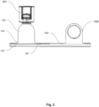
Fig. 3 shows a detailed view of the first channel of the cover ofFig. 2 . -
Fig. 4 shows a heat exchanger comprising a manifold with integrated expansion device. - The subject-matter of the present invention is, among others, a manifold for a heat exchanger for a motor vehicle. More specifically, the present invention discloses a simple, light, and cost efficient manifold that is able to withstand high fluid pressures, which can be up to 260 bar on the low-pressure side (LP) and up to 360 bar on the high-pressure side (HP), for high-pressure systems.
- A
manifold 102 for a high-pressure heat exchanger 100 may be configured for circulation of at least a first fluid (HP) and a second fluid (LP). - It is to be noted that the terms "first fluid" and "second fluid" may refer not only to two completely different fluids having, for example, different chemical composition, but also to substantially the same fluid having different properties. For instance, the first fluid (HP) may be high-pressure refrigerant (HP) and the second fluid (LP) may be the low-pressure refrigerant (LP). The third fluid (COOL) may be, for example, a coolant (COOL). For the sake of clarity and easy understanding of the drawings the (HP), (LP) and (COOL) abbreviations may be used throughout the descriptions instead of reference numbers.
- The
manifold 102 may comprise several elements which are assembled together. In view of the invention the focus is brought especially to at least afirst cover 124. The name "first" does not necessarily mean that saidcover 124 is first to covey the fluid. It depends on the application and flow pattern of a heat exchanger, therefore it shall not be limiting. - The
first manifold 102 may also comprise afirst header plate 120. Thefirst header plate 120 is configured to receive the tubes and it is to be attached to thefirst cover 124. It may be attached by, for example, crimping one element to the other what helps to pre-assembly the manifold. The structure is then brazed together along with other sub-components to provide a fluid-tight assembly. - The
manifold 102 may further comprise afirst header plate 120,afirst cover 124, and at least oneinternal plate 122, wherein thefirst header plate 120 is configured to be attached to thefirst cover 124 and at least one firstinternal plate 122 is arranged between thefirst header plate 120 and thefirst cover 124. - As mentioned in previous paragraph, the
first manifold 102 may comprise one or more firstinternal plates 122 arranged between thefirst header plate 120 and thefirst cover 124. Theinternal plates 122 may be regarded as spacers with openings which allow the first fluid (HP) and or second fluid (LP) circulation. Thefirst header plate 120 can include aplurality slots 126, and the firstinner plates 122 can also include a plurality ofslots 127 corresponding to theslots 126 of thefirst header plate 120. - The
manifold 102 may further comprise anexpansion device 800. - The
expansion device 800 is fixed directly to thefirst cover 124. In other words, after assembling the expansion device onto thecover 124, the two cannot be disassembled. It leads to an assembly, wherein the expansion device is integrated directly in the manifold. This brings numerous advantages. It reduces the path of the fluid and also makes the manifold simpler compared to the standalone manifold connected to the expansion device by means of pipes, blocks, etc. Needless to say it is also advantageous in view of type of fluid which is intended to circulate in the manifold, i.e. R744, R290 or mixture of two. Simple design and reduced of sub-components required reduce the risk of leakage or malfunction. - The
expansion device 800 may be located preferably on the path of the refrigerant fluid, namely the first fluid (HP). Therefore, thefirst cover 124 may further comprise at least afirst channel 102A, wherein thefirst channel 102A is extruded in saidcover 124. In other words, the first cover being a unitary block of metallic material may comprise extruded conduit therein. The conduit, i.e. thechannel 102A may comprise its axis of elongation. - One can also carry out an embodiment, in which the
expansion device 800 is fixed at the end of one of thechannels cover 124 which creates saidchannel specific expansion device 800 with a shaft of the valve long enough to penetrate into thechannel - The
cover 124 may also comprise afirst face 501. The term "face" relates to the side of the manifold 124 which can be easily distinguished by those skilled in the art. In other words, any shape other than sphere may comprise at least one side which is easily distinguished. - In the
cover 124 being the subject-matter of the invention, thefirst face 501 is substantially flat, so that it is entirely in contact with at least complementary face the firstinternal plate 122. Naturally saidinternal plate 122 also comprises at least one flat face in order to also be complementary to thefirst face 501 of thecover 124. Other shapes of the first face are also envisaged, as long as they are complementary with the corresponding face of theinternal plate 122. - Accordingly, the
first cover 124 may also comprise asecond face 502, thesecond face 502 being located on the opposite side of thefirst cover 124 with respect to thefirst face 501. - The
first cover 124 may also comprise thesecond channel 102B, wherein thechannels first face 501. - The
cover 124 may have a substantially rectangular shape, yet the cover of such a shape may comprise a lot of excessive material which not required, but increases weight of thefirst manifold 102. Therefore thefirst cover 124 comprises at least one essentially B-shaped cross- section, wherein the cross-section is substantially perpendicular with respect to thefirst face 501. This allows providing a light and strong structure. - In one of the embodiments, the
expansion device 800 may be located directly on thefirst channel 102A. However, it may be also envisaged that the expansion device is located on thesecond channel 102B depending on desired location on thefirst manifold 102. The termsfirst channel 102A and thesecond channel 102B may thus be used interchangeably, depending on the application of theexpansion device 800. - In order to reduce the packaging of the manifold 102, the
expansion device 800 may at least partially protrude into thefirst cover 124. It means that some elements, for example: a valve, may penetrate into the body of themanifold 102. - In order to integrate the expansion device into the
cover 124, said cover may comprise anest 111. Thenest 111 may be protruding outwardly from thecover 124, in the direction opposite to thefirst face 501. Alternatively, thenest 111 may be protruding inwardly, into thecover 124, i.e. in the direction of thefirst face 501. Thenest 111 may be configured for receiving theexpansion device 800, whereas theexpansion device 800 may comprise achamfer 811. Thechamfer 811 may be of the shape complementary to thenest 111. - Another object of the invention is a heat exchanger 100 for a motor vehicle comprising at least one
manifold 102 described above. - The heat exchanger 100 may further comprise already described
first manifold 102, asecond manifold 104 configured spaced apart from thefirst manifold 102 and a plurality of tubes 150 fluidically connected between thefirst manifold 102 and thesecond manifold 104. - The tubes 150 are configured to enable circulation of a first fluid (HP) and a second fluid (LP) between the
first manifold 102 and thesecond manifold 104. The tubes 150 may be divided into afirst section 160, and at least asecond section 170 wherein saidsections - The plurality of tubes 150 may be extruded tubes with micro ports, i.e., the plurality of tubes 150 may include micro channels extending along lengths of the tubes. The microchannels comprised in the tubes 150 forming each
section section - The plurality of tubes 150 may be at least partially encapsulated in a
housing 300 to enable circulation of at least a third fluid (COOL) at least asecond section 170. - In a preferred embodiment, the
first section 160 forms an internal heat exchanger (IHX) section, ant thesecond section 170 forms a chiller section. - Alternatively, the tubes 150 may be divided into a
first section 160, asecond section 170 and a third section 180, wherein saidsections - Preferably, the
expansion device 800 is located between thefirst section 160 and thesecond section 170. Theexpansion device 800 allows expansion of the first fluid (HP). InFig. 4 , the dashed line running across thehousing 300 is the support line showing exemplary division between thesections first section 160 and theexpansion device 800 itself transforms the first fluid (HP) into the second fluid LP) on the way, so it may enter the second section, i.e. the chiller section. - Notwithstanding the efficiency, in one of the embodiments, wherein the
expansion device 800 is unitary with thecover 124, another means of applying the invention are possible. Thecover 124 may comprise at least three cross sections in thechannel channel channel - In any case, the invention cannot and should not be limited to the embodiments specifically described in this document, as other embodiments might exist. The invention shall spread to any equivalent means and any technically operating combination of means.
Claims (15)
- A manifold (102) for a high-pressure heat exchanger (100) for circulation of at least a first fluid (HP) and a second fluid (LP) comprising: at least a first cover (124), and an expansion device (800), wherein the expansion device (800) is fixed directly to the first cover (124).
- The manifold (102) according to claim 1, wherein said manifold (102) further comprises: a first header plate (120), a first cover (124), and at least one internal plate (122), wherein the first header plate (120) is configured to be attached to the first cover (124) and at least one first internal plate (122) is arranged between the first header plate (120) and the first cover (124).
- The manifold(102) according to claim 2, wherein the first cover (124) further comprises at least a first channel (102A), wherein the first channel (102A) is extruded in said cover (124).
- The manifold (102) according to claim 3, wherein the cover (124) comprises a first face (501), wherein the first face (501) is substantially flat so that it is entirely in contact with at least complementary face the first internal plate (122).
- The manifold (102) according to claim 4, wherein the first cover (124) comprises a second face (502), the second face (502) being located on the opposite side of the first cover (124) with respect to the first face (501).
- The manifold (102) according to any of claims 4 or 5, wherein the first cover (124) comprises a second channel (102B), wherein the channels (102A, 102B) protrude in a direction opposite to the first face (501).
- The manifold (102) according to claim 6, wherein the first cover (124) comprises at least one essentially B-shaped cross- section, wherein the cross-section is substantially perpendicular with respect to the first face (501).
- The manifold (102) according to any of claims 3-7, wherein the expansion device (800) is located directly on the first channel (102A).
- The manifold (102) according to claim 8, wherein the expansion device (800) at least partially protrudes into the first cover (124).
- The manifold (102) according to any of the preceding claims, wherein cover (124) comprises a nest (111) configured for receiving the expansion device (800), and wherein the expansion device comprises a chamfer (811), wherein the chamfer (811) is complementary to the nest (111).
- The manifold (102) according to any of the preceding claims, wherein the expansion device is unitary with the cover (124).
- A heat exchanger (100) for a motor vehicle comprising at least one manifold (102) according to any of the preceding claims.
- The heat exchanger (100) according to claim 12, wherein the heat exchanger (100) further comprises: a first manifold (102); a second manifold (104) configured spaced apart from the first manifold (102); and a plurality of tubes (150) fluidically connected between the first manifold (102) and the second manifold (104), wherein the tubes (150) are configured to enable circulation of a first fluid (HP) and a second fluid (LP) between the first manifold (102) and the second manifold (104), wherein the plurality of tubes (150) comprises a first section (160), and at least a second section (170), wherein said sections (160, 170) are stacked one above the other, wherein the plurality of tubes (150) is at least partially encapsulated in a housing (300) to enable circulation of at least a third fluid (COOL) at least a second section (170).
- The heat exchanger (100) according to claim 13, wherein first section (160) forms an internal heat exchanger (IHX) section, the second section (170) forms a chiller section.
- The heat exchanger (100) according to any of claims 13 or 14, wherein the expansion device is located between the first section (160) and the second section (170).
Priority Applications (1)
| Application Number | Priority Date | Filing Date | Title |
|---|---|---|---|
| EP23218958.9A EP4574476A1 (en) | 2023-12-21 | 2023-12-21 | A manifold |
Applications Claiming Priority (1)
| Application Number | Priority Date | Filing Date | Title |
|---|---|---|---|
| EP23218958.9A EP4574476A1 (en) | 2023-12-21 | 2023-12-21 | A manifold |
Publications (1)
| Publication Number | Publication Date |
|---|---|
| EP4574476A1 true EP4574476A1 (en) | 2025-06-25 |
Family
ID=89224761
Family Applications (1)
| Application Number | Title | Priority Date | Filing Date |
|---|---|---|---|
| EP23218958.9A Pending EP4574476A1 (en) | 2023-12-21 | 2023-12-21 | A manifold |
Country Status (1)
| Country | Link |
|---|---|
| EP (1) | EP4574476A1 (en) |
Citations (6)
| Publication number | Priority date | Publication date | Assignee | Title |
|---|---|---|---|---|
| JPH09280693A (en) * | 1996-04-10 | 1997-10-31 | Calsonic Corp | Laminate type heat excanger |
| JP2000028227A (en) * | 1998-07-09 | 2000-01-28 | Denso Corp | Stacked evaporator |
| US6581679B2 (en) * | 2000-11-07 | 2003-06-24 | Behr Gmbh & Co. | Heat exchanger and method for producing a heat exchanger |
| US8037929B2 (en) * | 2004-12-16 | 2011-10-18 | Showa Denko K.K. | Evaporator |
| WO2014136366A1 (en) * | 2013-03-04 | 2014-09-12 | カルソニックカンセイ株式会社 | Evaporator |
| US9605883B2 (en) * | 2011-12-05 | 2017-03-28 | Denso Corporation | Heat pump cycle |
-
2023
- 2023-12-21 EP EP23218958.9A patent/EP4574476A1/en active Pending
Patent Citations (6)
| Publication number | Priority date | Publication date | Assignee | Title |
|---|---|---|---|---|
| JPH09280693A (en) * | 1996-04-10 | 1997-10-31 | Calsonic Corp | Laminate type heat excanger |
| JP2000028227A (en) * | 1998-07-09 | 2000-01-28 | Denso Corp | Stacked evaporator |
| US6581679B2 (en) * | 2000-11-07 | 2003-06-24 | Behr Gmbh & Co. | Heat exchanger and method for producing a heat exchanger |
| US8037929B2 (en) * | 2004-12-16 | 2011-10-18 | Showa Denko K.K. | Evaporator |
| US9605883B2 (en) * | 2011-12-05 | 2017-03-28 | Denso Corporation | Heat pump cycle |
| WO2014136366A1 (en) * | 2013-03-04 | 2014-09-12 | カルソニックカンセイ株式会社 | Evaporator |
Similar Documents
| Publication | Publication Date | Title |
|---|---|---|
| US5107926A (en) | Manifold assembly for a parallel flow heat exchanger | |
| US9103598B2 (en) | Heat exchanger for two fluids, in particular a storage evaporator for an air conditioning device | |
| US20120031601A1 (en) | Multichannel tubes with deformable webs | |
| US10989479B2 (en) | Integrated liquid air cooled condenser and low temperature radiator | |
| US6189603B1 (en) | Double heat exchanger having condenser and radiator | |
| US10359238B2 (en) | Heat exchanger and side plate | |
| US11384988B2 (en) | Heat exchanger | |
| US7013952B2 (en) | Stack type heat exchanger | |
| US7051796B2 (en) | Heat exchanger | |
| JP2007163004A (en) | Heat exchanger | |
| JP2006329511A (en) | Heat exchanger | |
| CN221593595U (en) | Heat exchanger | |
| WO2022017738A1 (en) | A header-tank assembly | |
| WO2019058514A1 (en) | Heat exchanger, refrigeration cycle device, and method for manufacturing heat exchanger | |
| EP4464965A1 (en) | A heat exchanger | |
| EP4574477A1 (en) | A heat exchanger | |
| EP4574475A1 (en) | A heat exchanger | |
| JP6940027B1 (en) | Heat exchanger and air conditioner with heat exchanger | |
| EP4308870B1 (en) | Microchannel heat exchanger for appliance condenser | |
| CN120835978A (en) | Heat exchanger and air conditioning device having the same | |
| EP4464966A1 (en) | A heat exchanger | |
| JP2007040605A (en) | Heat exchanger for multistage compression type refrigeration cycle device | |
| EP4317889A1 (en) | A tube bundle for aheat exchanger | |
| EP3757503A1 (en) | Heat exchanger with a connector | |
| EP4474745A1 (en) | A heat exchanger for a vehicle |
Legal Events
| Date | Code | Title | Description |
|---|---|---|---|
| PUAI | Public reference made under article 153(3) epc to a published international application that has entered the european phase |
Free format text: ORIGINAL CODE: 0009012 |
|
| STAA | Information on the status of an ep patent application or granted ep patent |
Free format text: STATUS: THE APPLICATION HAS BEEN PUBLISHED |
|
| AK | Designated contracting states |
Kind code of ref document: A1 Designated state(s): AL AT BE BG CH CY CZ DE DK EE ES FI FR GB GR HR HU IE IS IT LI LT LU LV MC ME MK MT NL NO PL PT RO RS SE SI SK SM TR |
|
| RAP1 | Party data changed (applicant data changed or rights of an application transferred) |
Owner name: VALEO ELECTRIFICATION |
|
| STAA | Information on the status of an ep patent application or granted ep patent |
Free format text: STATUS: THE APPLICATION IS DEEMED TO BE WITHDRAWN |