EP4574437A1 - Inkjet image forming apparatus - Google Patents
Inkjet image forming apparatus Download PDFInfo
- Publication number
- EP4574437A1 EP4574437A1 EP24216744.3A EP24216744A EP4574437A1 EP 4574437 A1 EP4574437 A1 EP 4574437A1 EP 24216744 A EP24216744 A EP 24216744A EP 4574437 A1 EP4574437 A1 EP 4574437A1
- Authority
- EP
- European Patent Office
- Prior art keywords
- image forming
- base material
- precoating
- printing base
- position adjustment
- Prior art date
- Legal status (The legal status is an assumption and is not a legal conclusion. Google has not performed a legal analysis and makes no representation as to the accuracy of the status listed.)
- Granted
Links
Images



Classifications
-
- B—PERFORMING OPERATIONS; TRANSPORTING
- B41—PRINTING; LINING MACHINES; TYPEWRITERS; STAMPS
- B41J—TYPEWRITERS; SELECTIVE PRINTING MECHANISMS, i.e. MECHANISMS PRINTING OTHERWISE THAN FROM A FORME; CORRECTION OF TYPOGRAPHICAL ERRORS
- B41J11/00—Devices or arrangements of selective printing mechanisms, e.g. ink-jet printers or thermal printers, for supporting or handling copy material in sheet or web form
- B41J11/0015—Devices or arrangements of selective printing mechanisms, e.g. ink-jet printers or thermal printers, for supporting or handling copy material in sheet or web form for treating before, during or after printing or for uniform coating or laminating the copy material before or after printing
-
- B—PERFORMING OPERATIONS; TRANSPORTING
- B41—PRINTING; LINING MACHINES; TYPEWRITERS; STAMPS
- B41J—TYPEWRITERS; SELECTIVE PRINTING MECHANISMS, i.e. MECHANISMS PRINTING OTHERWISE THAN FROM A FORME; CORRECTION OF TYPOGRAPHICAL ERRORS
- B41J11/00—Devices or arrangements of selective printing mechanisms, e.g. ink-jet printers or thermal printers, for supporting or handling copy material in sheet or web form
- B41J11/0015—Devices or arrangements of selective printing mechanisms, e.g. ink-jet printers or thermal printers, for supporting or handling copy material in sheet or web form for treating before, during or after printing or for uniform coating or laminating the copy material before or after printing
- B41J11/002—Curing or drying the ink on the copy materials, e.g. by heating or irradiating
- B41J11/0021—Curing or drying the ink on the copy materials, e.g. by heating or irradiating using irradiation
- B41J11/00214—Curing or drying the ink on the copy materials, e.g. by heating or irradiating using irradiation using UV radiation
-
- B—PERFORMING OPERATIONS; TRANSPORTING
- B41—PRINTING; LINING MACHINES; TYPEWRITERS; STAMPS
- B41J—TYPEWRITERS; SELECTIVE PRINTING MECHANISMS, i.e. MECHANISMS PRINTING OTHERWISE THAN FROM A FORME; CORRECTION OF TYPOGRAPHICAL ERRORS
- B41J11/00—Devices or arrangements of selective printing mechanisms, e.g. ink-jet printers or thermal printers, for supporting or handling copy material in sheet or web form
- B41J11/008—Controlling printhead for accurately positioning print image on printing material, e.g. with the intention to control the width of margins
-
- B—PERFORMING OPERATIONS; TRANSPORTING
- B41—PRINTING; LINING MACHINES; TYPEWRITERS; STAMPS
- B41J—TYPEWRITERS; SELECTIVE PRINTING MECHANISMS, i.e. MECHANISMS PRINTING OTHERWISE THAN FROM A FORME; CORRECTION OF TYPOGRAPHICAL ERRORS
- B41J11/00—Devices or arrangements of selective printing mechanisms, e.g. ink-jet printers or thermal printers, for supporting or handling copy material in sheet or web form
- B41J11/0095—Detecting means for copy material, e.g. for detecting or sensing presence of copy material or its leading or trailing end
-
- B—PERFORMING OPERATIONS; TRANSPORTING
- B41—PRINTING; LINING MACHINES; TYPEWRITERS; STAMPS
- B41J—TYPEWRITERS; SELECTIVE PRINTING MECHANISMS, i.e. MECHANISMS PRINTING OTHERWISE THAN FROM A FORME; CORRECTION OF TYPOGRAPHICAL ERRORS
- B41J11/00—Devices or arrangements of selective printing mechanisms, e.g. ink-jet printers or thermal printers, for supporting or handling copy material in sheet or web form
- B41J11/36—Blanking or long feeds; Feeding to a particular line, e.g. by rotation of platen or feed roller
- B41J11/42—Controlling printing material conveyance for accurate alignment of the printing material with the printhead; Print registering
- B41J11/46—Controlling printing material conveyance for accurate alignment of the printing material with the printhead; Print registering by marks or formations on the paper being fed
-
- B—PERFORMING OPERATIONS; TRANSPORTING
- B41—PRINTING; LINING MACHINES; TYPEWRITERS; STAMPS
- B41J—TYPEWRITERS; SELECTIVE PRINTING MECHANISMS, i.e. MECHANISMS PRINTING OTHERWISE THAN FROM A FORME; CORRECTION OF TYPOGRAPHICAL ERRORS
- B41J2/00—Typewriters or selective printing mechanisms characterised by the printing or marking process for which they are designed
- B41J2/005—Typewriters or selective printing mechanisms characterised by the printing or marking process for which they are designed characterised by bringing liquid or particles selectively into contact with a printing material
- B41J2/01—Ink jet
- B41J2/21—Ink jet for multi-colour printing
- B41J2/2107—Ink jet for multi-colour printing characterised by the ink properties
- B41J2/2114—Ejecting specialized liquids, e.g. transparent or processing liquids
-
- B—PERFORMING OPERATIONS; TRANSPORTING
- B41—PRINTING; LINING MACHINES; TYPEWRITERS; STAMPS
- B41J—TYPEWRITERS; SELECTIVE PRINTING MECHANISMS, i.e. MECHANISMS PRINTING OTHERWISE THAN FROM A FORME; CORRECTION OF TYPOGRAPHICAL ERRORS
- B41J3/00—Typewriters or selective printing or marking mechanisms characterised by the purpose for which they are constructed
- B41J3/407—Typewriters or selective printing or marking mechanisms characterised by the purpose for which they are constructed for marking on special material
-
- C—CHEMISTRY; METALLURGY
- C09—DYES; PAINTS; POLISHES; NATURAL RESINS; ADHESIVES; COMPOSITIONS NOT OTHERWISE PROVIDED FOR; APPLICATIONS OF MATERIALS NOT OTHERWISE PROVIDED FOR
- C09D—COATING COMPOSITIONS, e.g. PAINTS, VARNISHES OR LACQUERS; FILLING PASTES; CHEMICAL PAINT OR INK REMOVERS; INKS; CORRECTING FLUIDS; WOODSTAINS; PASTES OR SOLIDS FOR COLOURING OR PRINTING; USE OF MATERIALS THEREFOR
- C09D11/00—Inks
- C09D11/02—Printing inks
- C09D11/10—Printing inks based on artificial resins
- C09D11/101—Inks specially adapted for printing processes involving curing by wave energy or particle radiation, e.g. with UV-curing following the printing
-
- C—CHEMISTRY; METALLURGY
- C09—DYES; PAINTS; POLISHES; NATURAL RESINS; ADHESIVES; COMPOSITIONS NOT OTHERWISE PROVIDED FOR; APPLICATIONS OF MATERIALS NOT OTHERWISE PROVIDED FOR
- C09D—COATING COMPOSITIONS, e.g. PAINTS, VARNISHES OR LACQUERS; FILLING PASTES; CHEMICAL PAINT OR INK REMOVERS; INKS; CORRECTING FLUIDS; WOODSTAINS; PASTES OR SOLIDS FOR COLOURING OR PRINTING; USE OF MATERIALS THEREFOR
- C09D11/00—Inks
- C09D11/50—Sympathetic, colour changing or similar inks
-
- C—CHEMISTRY; METALLURGY
- C09—DYES; PAINTS; POLISHES; NATURAL RESINS; ADHESIVES; COMPOSITIONS NOT OTHERWISE PROVIDED FOR; APPLICATIONS OF MATERIALS NOT OTHERWISE PROVIDED FOR
- C09D—COATING COMPOSITIONS, e.g. PAINTS, VARNISHES OR LACQUERS; FILLING PASTES; CHEMICAL PAINT OR INK REMOVERS; INKS; CORRECTING FLUIDS; WOODSTAINS; PASTES OR SOLIDS FOR COLOURING OR PRINTING; USE OF MATERIALS THEREFOR
- C09D11/00—Inks
- C09D11/54—Inks based on two liquids, one liquid being the ink, the other liquid being a reaction solution, a fixer or a treatment solution for the ink
-
- B—PERFORMING OPERATIONS; TRANSPORTING
- B41—PRINTING; LINING MACHINES; TYPEWRITERS; STAMPS
- B41J—TYPEWRITERS; SELECTIVE PRINTING MECHANISMS, i.e. MECHANISMS PRINTING OTHERWISE THAN FROM A FORME; CORRECTION OF TYPOGRAPHICAL ERRORS
- B41J11/00—Devices or arrangements of selective printing mechanisms, e.g. ink-jet printers or thermal printers, for supporting or handling copy material in sheet or web form
- B41J11/0015—Devices or arrangements of selective printing mechanisms, e.g. ink-jet printers or thermal printers, for supporting or handling copy material in sheet or web form for treating before, during or after printing or for uniform coating or laminating the copy material before or after printing
- B41J11/002—Curing or drying the ink on the copy materials, e.g. by heating or irradiating
- B41J11/0024—Curing or drying the ink on the copy materials, e.g. by heating or irradiating using conduction means, e.g. by using a heated platen
-
- B—PERFORMING OPERATIONS; TRANSPORTING
- B41—PRINTING; LINING MACHINES; TYPEWRITERS; STAMPS
- B41J—TYPEWRITERS; SELECTIVE PRINTING MECHANISMS, i.e. MECHANISMS PRINTING OTHERWISE THAN FROM A FORME; CORRECTION OF TYPOGRAPHICAL ERRORS
- B41J2203/00—Embodiments of or processes related to the control of the printing process
- B41J2203/01—Inspecting a printed medium or a medium to be printed using a sensing device
Definitions
- the present disclosure relates to an inkjet image forming apparatus which forms an image on a printing base material by an inkjet method.
- a precoating may be applied to the printing base material. Further, in such an image forming apparatus, as described in JP2005-053088 , a position adjustment mark printed on a surface of the printing base material is read by an optical sensor, and based on the read position adjustment mark, an image forming position is adjusted or a registration at the time of color printing is performed.
- the printing base material has a certain degree of stretchability, such as a plastic film, the printing base material may be stretched during conveying, and the position of the position adjustment mark may be shifted. As a result, there is a problem that the image forming position is shifted or color mixing occurs at the time of color printing.
- An inkjet image forming apparatus includes an image forming part, a precoating unit, a fluorescent coating surface, a UV lighting device, and a camera.
- the image forming part ejects ink on a printing base material conveyed in a predetermined conveyance direction to form an image.
- the precoating unit is arranged on an upstream side of the image forming part in the conveyance direction, and ejects a precoating liquid having a property of absorbing UV light.
- the fluorescent coating surface is arranged between the image forming part and the precoating unit, and on the fluorescent coating surface, the printing base material is conveyed.
- the UV lighting device irradiates the printing base material conveyed on the fluorescent coating surface with UV light.
- the camera photographs the printing bae material irradiated with the UV light.
- a position adjustment mark is formed on the printing base material by using the precoating liquid in the precoating unit, the formed position adjustment mark is irradiated with the UV light by the UV lighting device, the irradiated position adjustment mark is photographed by the camera, and the image forming part forms an image based on the photographed position adjustment mark.
- FIG. 1 is a front view schematically showing an internal configuration of the inkjet image forming apparatus 1.
- the inkjet image forming apparatus 1 includes a feed roller 3, a precoating unit 5, a photographing part 7, an image forming part 9, a drying part 11, and a rewinding roller 13 in order along a conveyance direction of a printing base material M.
- the inkjet image forming apparatus 1 further includes a conveying plate 15 disposed below the precoating unit 5, the photographing part 7, and the image forming part9 between the feed roller 3 and the drying part 11.
- the feed roller 3 will be described.
- the long printing base material M is wound around the feed roller 3.
- the printing base material M is fed out in the conveyance direction X.
- the precoating unit 5 applies a precoating to the printing base material M fed from the feed roller 3.
- the precoating unit 5 includes a precoating head unit 21 which ejects a precoating liquid.
- the precoating head unit 21 is electrically connected to a control part 61.
- FIG. 2 is a plan view showing the precoating head unit 21.
- the precoating head unit 21 is provided with three print heads 23 and a plate 25 for supporting the three print heads 23.
- the three print heads 23 are disposed in a staggered pattern along the width direction Y (intersecting the conveyance direction X) so as to have a length approximately equal to the width of the printing base material M (line head system), and are supported by the plate 25.
- a precoating liquid is supplied from a precoating liquid supply source to the three print heads 23.
- the print head 23 includes a large number of nozzles and piezoelectric element provided in each nozzle.
- the ejection port of the nozzle is opened on the lower surface of the print head 23.
- the piezoelectric element is deformed by applying a voltage to the piezoelectric element, and the precoating liquid in the nozzle is ejected downward through the ejection port.
- the components of the precoating liquid are, for example, 10% polyester resin (Trade name, PESRESIN A-640, manufactured by TAKAMATSU OIL&HAT CO., LTD.), 0.04% surfactant (Trade name, Surfynol 440, manufactured by Nisshin Chemical co., ltd.), 25% propylene glycol, and 64.96% water.
- the surfactant contains a component having an acetylene bond having a property of absorbing UV light.
- the photographing part 7 includes a light shielding box 31 having an open lower surface, and a UV lighting device 33 and a camera 35 arranged in the light shielding box 31.
- the light shielding box 31 is arranged such that the open lower surface faces the printing base material M passed through the precoating unit 5.
- the UV lighting device 33 irradiates the printing base material M passing through the precoating unit 5 with UV light in the light shielding box 31.
- the camera 35 photographs the printing base material M irradiated by the UV lighting device 33.
- the camera 35 is electrically connected to the control part 61.
- the image forming part 9 forms an image on the printing base material M by an inkjet method.
- the image forming part 9 includes four image forming head units 41B, 41C, 41M, and 41Y (collectively referred to as the image forming head unit 41) corresponding to the inks of four colors (black, cyan, magenta, and yellow).
- the four image forming head units 41 are arranged in order along the conveyance direction X.
- the four image forming head units 41 are electrically connected to the control part 61.
- the image forming head unit 41 has the same configuration as the precoating head unit 21 of the precoating unit 5 shown in FIG. 2 , and includes the three print heads 43 and the plate 45 for supporting the three print heads 43.
- the black, cyan, magenta, and yellow inks are supplied to the three print heads 43 of the four image forming head units 41, respectively.
- the print head 43 includes a large number of nozzles and piezoelectric elements provided in each nozzle.
- the ejection port of the nozzle is opened on the lower surface of the print head 43.
- the piezoelectric element is deformed by applying a voltage to the piezoelectric element, and the ink in the nozzle is ejected downward from the ejection port.
- the drying part 11 dries the image formed on the printing base material M in the image forming part 9.
- the drying part 11 includes a heat drum 51, and upstream-side and downstream-side tension rollers 53 and 55 arranged on the upstream side and the downstream side of the heat drum 51.
- the printing base material M passing through the image forming part 9 is wound around the heat drum 51 between the upstream-side and downstream-side tension rollers 53 and 55.
- the heat drum 51 is heated to heat the printing base material M conveyed along the surface.
- the end of the printing base material M is fixed to the rewinding roller 13.
- the rewinding roller 13 is connected to a motor (not shown) and is rotated. By rotating the rewinding roller 13 in a predetermined direction at a predetermined rotational speed by the motor, the printing base material M is fed out from the feed roller 3.
- the fed printing base material M passes through the precoating unit 5, the photographing part 7, the image forming part 9, and the drying part 11, and is wound around the rewinding roller 13.
- the conveying plate 15 will be described. As shown in FIG. 1 , the conveying plate 15 is disposed below the precoating unit 5, the photographing part 7, and the image forming part 9. The upper surface of the conveying plate 15 is formed flat. As shown in FIG. 2 , a width of the conveying plate 15 is larger than a width of the printing base material M and all the head units 21 and 41. A heat source (not shown) is provided below the conveying plate 15 to heat the conveying plate 15 to a predetermined temperature.
- the conveying plate 15 is made of metal, for example.
- a fluorescent coating material is applied to an area facing the photographing part 7.
- the surface applied with the fluorescent coating material is defined as a fluorescent surface 15a.
- control part 61 controls the precoating head unit 21 of the precoating unit 5 and the four image forming head units 41 of the image forming part 9.
- image data of an image photographed by the camera 35 of the photographing part 7 printed is input.
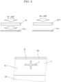
- FIG. 3 is a view explaining the operation of the photographing part 7.
- the motor is driven to rotate the rewinding roller 13, and the printing base material M is fed out from the feed roller 3.
- the control part 61 controls the precoating unit 5 to form a position adjustment mark T at a predetermined position outside an image forming region R1 of the printing base material M using the precoating liquid, as shown in the lower view of FIG. 3 .
- the precoating unit 5 performs a precoating for ejecting the precoating liquid to an image forming region R2 as usual.
- the position adjustment mark T is irradiated with UV light by the UV lighting device 33.
- the position adjustment mark T is irradiated with visible light, since the printing base material M and the precoating liquid are transparent, only the fluorescent surface 15a of the conveying plate 15 is visible, and the position adjustment mark T cannot be distinguished from other area.
- the position adjustment mark T when the position adjustment mark T is irradiated with UV light, as shown in the lower view of FIG. 3 , the area T' (the printing base material M) other than the position adjustment mark T transmits UV light. Then, as shown in the upper left view of FIG. 3 , the transmitted UV light irradiates the fluorescent surface 15a of the conveying plate 15, and the fluorescent surface 15a fluoresces. On the other hand, as shown in the upper right view of FIG. 3 , since the position adjustment mark T is formed of the precoating liquid having a property of absorbing UV light, the UV light is absorbed. Therefore, the fluorescent surface 15a below the position adjustment mark T is not irradiated with UV light and does not fluoresce. As a result, as shown in the lower view of FIG. 3 , the position adjustment mark T becomes darker than the other area T' and is visualized. Since the UV lighting device 33 is surrounded by the light shielding box 31, external light is shielded and the position adjustment mark T is more clearly visible.
- the visualized position adjustment mark T is photographed by the camera 35.
- the photographed position adjustment mark T is outputted to the control part 61.
- the control part 61 adjusts a printing position of an image to be formed, based on the mark T.
- the image forming part 9 ejects the ink of the predetermined color from the print head 43 of the image forming head unit 41 based on the image data to the adjusted printing position, and then an image is formed on the printing base material M.
- the printing base material M on which the image is formed is conveyed to the drying part 11. In the drying part 11, the ink is completely dried. Thereafter, the printing base material M is rewound by the rewinding roller 13.
- the printing position of the image by the image forming head unit 41 of the image forming part 9 is adjusted based on the position adjustment mark T formed by the precoating unit 5 (registration).
- the printing base material M is made of material having a certain degree of stretchability, such as a plastic film, there is a case where the printing base material M is stretched by being pulled when it is conveyed by both rollers 3 and 13. Therefore, for example, when the position adjustment mark is previously written on the printing base material M, the position of the position adjustment mark may be shifted.
- the position adjustment mark T is formed by the precoating immediately before the image forming operation. Therefore, the position adjustment mark T and the image are formed on the printing base material M under the same condition (stretched state). Therefore, the position adjustment accuracy is improved, and an excellent image without the color mixing of the inks and the like can be formed.
- FIG. 4A shows a test image of the present example in which the position adjustment of the present embodiment is performed
- FIG. 5B shows a test image of a comparative example in which the normal position adjustment is performed.
- the boundaries of the images of different colors are distinct.
- FIG. 4B in the comparative example, it can be seen that the boundaries of the images of different colors are blurred and mixed.
- the printing base material M is conveyed along the upper surface of the conveying plate 15, there is a possibility that the fluorescent surface 15a comes into contact with the printing base material M and peels off. For this reason, it is preferable that the printing base material M is conveyed while being slightly lifted from the upper surface of the conveying plate 15.
- the image forming head unit 41 of the four colors is used, but the present disclosure is not limited to the four colors and may be more or less than four colors.
- the head units 21 and 41 are not limited to the line head system. However, the line head system is preferable because the printing speed can be increased. Although a long plastic film (PET film) is used as the printing base material M, a cut film may be used.
- PET film plastic film
Landscapes
- Chemical & Material Sciences (AREA)
- Life Sciences & Earth Sciences (AREA)
- Engineering & Computer Science (AREA)
- Materials Engineering (AREA)
- Wood Science & Technology (AREA)
- Organic Chemistry (AREA)
- Chemical Kinetics & Catalysis (AREA)
- Health & Medical Sciences (AREA)
- General Health & Medical Sciences (AREA)
- Toxicology (AREA)
- Ink Jet (AREA)
Abstract
Description
- The present disclosure relates to an inkjet image forming apparatus which forms an image on a printing base material by an inkjet method.
- In the inkjet type image forming apparatus, in order to enhance an adhesion of ink to a printing base material, a precoating may be applied to the printing base material. Further, in such an image forming apparatus, as described in
JP2005-053088 - However, when the position adjustment mark is printed on the printing base material in advance, if the printing base material has a certain degree of stretchability, such as a plastic film, the printing base material may be stretched during conveying, and the position of the position adjustment mark may be shifted. As a result, there is a problem that the image forming position is shifted or color mixing occurs at the time of color printing.
- An inkjet image forming apparatus according to the present disclosure includes an image forming part, a precoating unit, a fluorescent coating surface, a UV lighting device, and a camera. The image forming part ejects ink on a printing base material conveyed in a predetermined conveyance direction to form an image. The precoating unit is arranged on an upstream side of the image forming part in the conveyance direction, and ejects a precoating liquid having a property of absorbing UV light. The fluorescent coating surface is arranged between the image forming part and the precoating unit, and on the fluorescent coating surface, the printing base material is conveyed. The UV lighting device irradiates the printing base material conveyed on the fluorescent coating surface with UV light. The camera photographs the printing bae material irradiated with the UV light. A position adjustment mark is formed on the printing base material by using the precoating liquid in the precoating unit, the formed position adjustment mark is irradiated with the UV light by the UV lighting device, the irradiated position adjustment mark is photographed by the camera, and the image forming part forms an image based on the photographed position adjustment mark.
-
-
FIG. 1 is a front view schematically showing an inkjet image forming apparatus according to one embodiment of the present disclosure. -
FIG. 2 is a plan view showing a head unit, in the inkjet image forming apparatus according to the embodiment of the present disclosure. -
FIG. 3 is a view explaining an operation of a photographing part, in the inkjet image forming apparatus according to the embodiment of the present disclosure. -
FIG. 4A shows an image in the present example, in the inkjet image forming apparatus according to the embodiment of the present disclosure. -
FIG. 4B shows an image in the comparative example, in the inkjet image forming apparatus according to the embodiment of the present disclosure. - Hereinafter, with reference to the drawings, an inkjet image forming apparatus according to one embodiment of the present disclosure will be described.
- With reference to
FIG. 1 , an entire configuration of the inkjet image forming apparatus 1 will be described.FIG. 1 is a front view schematically showing an internal configuration of the inkjet image forming apparatus 1. - The inkjet image forming apparatus 1 includes a
feed roller 3, a precoatingunit 5, a photographingpart 7, animage forming part 9, a dryingpart 11, and a rewindingroller 13 in order along a conveyance direction of a printing base material M. The inkjet image forming apparatus 1 further includes a conveyingplate 15 disposed below the precoatingunit 5, the photographingpart 7, and the image forming part9 between thefeed roller 3 and thedrying part 11. - First, the
feed roller 3 will be described. The long printing base material M is wound around thefeed roller 3. When thefeed roller 3 is rotated, the printing base material M is fed out in the conveyance direction X. - Next, the precoating
unit 5 will be described. The precoatingunit 5 applies a precoating to the printing base material M fed from thefeed roller 3. The precoatingunit 5 includes a precoatinghead unit 21 which ejects a precoating liquid. The precoatinghead unit 21 is electrically connected to acontrol part 61. - With reference to
FIG. 2 , the precoatinghead unit 21 will be described.FIG. 2 is a plan view showing the precoatinghead unit 21. The precoatinghead unit 21 is provided with three print heads 23 and a plate 25 for supporting the three print heads 23. The three print heads 23 are disposed in a staggered pattern along the width direction Y (intersecting the conveyance direction X) so as to have a length approximately equal to the width of the printing base material M (line head system), and are supported by the plate 25. A precoating liquid is supplied from a precoating liquid supply source to the three print heads 23. - The print head 23 includes a large number of nozzles and piezoelectric element provided in each nozzle. The ejection port of the nozzle is opened on the lower surface of the print head 23. The piezoelectric element is deformed by applying a voltage to the piezoelectric element, and the precoating liquid in the nozzle is ejected downward through the ejection port.
- The components of the precoating liquid are, for example, 10% polyester resin (Trade name, PESRESIN A-640, manufactured by TAKAMATSU OIL&HAT CO., LTD.), 0.04% surfactant (Trade name, Surfynol 440, manufactured by Nisshin Chemical co., ltd.), 25% propylene glycol, and 64.96% water. Among them, the surfactant (dispersant) contains a component having an acetylene bond having a property of absorbing UV light.
- Next, the photographing
part 7 will be described with reference toFIG. 1 . The photographingpart 7 includes alight shielding box 31 having an open lower surface, and aUV lighting device 33 and acamera 35 arranged in thelight shielding box 31. Thelight shielding box 31 is arranged such that the open lower surface faces the printing base material M passed through the precoatingunit 5. - The
UV lighting device 33 irradiates the printing base material M passing through the precoatingunit 5 with UV light in thelight shielding box 31. Thecamera 35 photographs the printing base material M irradiated by theUV lighting device 33. Thecamera 35 is electrically connected to thecontrol part 61. - Next, the
image forming part 9 will be described. Theimage forming part 9 forms an image on the printing base material M by an inkjet method. Theimage forming part 9 includes four image forminghead units control part 61. - The image forming head unit 41 has the same configuration as the precoating
head unit 21 of the precoatingunit 5 shown inFIG. 2 , and includes the three print heads 43 and the plate 45 for supporting the three print heads 43. The black, cyan, magenta, and yellow inks are supplied to the three print heads 43 of the four image forming head units 41, respectively. - The print head 43 includes a large number of nozzles and piezoelectric elements provided in each nozzle. The ejection port of the nozzle is opened on the lower surface of the print head 43. The piezoelectric element is deformed by applying a voltage to the piezoelectric element, and the ink in the nozzle is ejected downward from the ejection port.
- Next, the drying
part 11 will be described with reference toFIG. 1 . The dryingpart 11 dries the image formed on the printing base material M in theimage forming part 9. The dryingpart 11 includes aheat drum 51, and upstream-side and downstream-side tension rollers heat drum 51. The printing base material M passing through theimage forming part 9 is wound around theheat drum 51 between the upstream-side and downstream-side tension rollers heat drum 51 is heated to heat the printing base material M conveyed along the surface. - Next, the rewinding
roller 13 will be described. The end of the printing base material M is fixed to the rewindingroller 13. The rewindingroller 13 is connected to a motor (not shown) and is rotated. By rotating the rewindingroller 13 in a predetermined direction at a predetermined rotational speed by the motor, the printing base material M is fed out from thefeed roller 3. The fed printing base material M passes through theprecoating unit 5, the photographingpart 7, theimage forming part 9, and the dryingpart 11, and is wound around the rewindingroller 13. - Next, the conveying
plate 15 will be described. As shown inFIG. 1 , the conveyingplate 15 is disposed below theprecoating unit 5, the photographingpart 7, and theimage forming part 9. The upper surface of the conveyingplate 15 is formed flat. As shown inFIG. 2 , a width of the conveyingplate 15 is larger than a width of the printing base material M and all thehead units 21 and 41. A heat source (not shown) is provided below the conveyingplate 15 to heat the conveyingplate 15 to a predetermined temperature. The conveyingplate 15 is made of metal, for example. - On the upper surface of the conveying
plate 15, a fluorescent coating material is applied to an area facing the photographingpart 7. The surface applied with the fluorescent coating material (the fluorescent coating material coated surface) is defined as afluorescent surface 15a. - Next, the
control part 61 will be described. As shown inFIG. 1 , thecontrol part 61 controls theprecoating head unit 21 of theprecoating unit 5 and the four image forming head units 41 of theimage forming part 9. To thecontrol part 61, image data of an image photographed by thecamera 35 of the photographingpart 7 printed is input. - An image forming operation of the inkjet image forming apparatus 1 having the above configuration will be described with reference to
FIG. 3. FIG. 3 is a view explaining the operation of the photographingpart 7. - During the image forming operation, the motor is driven to rotate the rewinding
roller 13, and the printing base material M is fed out from thefeed roller 3. When the printing base material M is conveyed below theprecoating unit 5, thecontrol part 61 controls theprecoating unit 5 to form a position adjustment mark T at a predetermined position outside an image forming region R1 of the printing base material M using the precoating liquid, as shown in the lower view ofFIG. 3 . Theprecoating unit 5 performs a precoating for ejecting the precoating liquid to an image forming region R2 as usual. - When the printing base material M is conveyed and the formed position adjustment mark T is conveyed below the photographing
part 7, the position adjustment mark T is irradiated with UV light by theUV lighting device 33. When the position adjustment mark T is irradiated with visible light, since the printing base material M and the precoating liquid are transparent, only thefluorescent surface 15a of the conveyingplate 15 is visible, and the position adjustment mark T cannot be distinguished from other area. - However, when the position adjustment mark T is irradiated with UV light, as shown in the lower view of
FIG. 3 , the area T' (the printing base material M) other than the position adjustment mark T transmits UV light. Then, as shown in the upper left view ofFIG. 3 , the transmitted UV light irradiates thefluorescent surface 15a of the conveyingplate 15, and thefluorescent surface 15a fluoresces. On the other hand, as shown in the upper right view ofFIG. 3 , since the position adjustment mark T is formed of the precoating liquid having a property of absorbing UV light, the UV light is absorbed. Therefore, thefluorescent surface 15a below the position adjustment mark T is not irradiated with UV light and does not fluoresce. As a result, as shown in the lower view ofFIG. 3 , the position adjustment mark T becomes darker than the other area T' and is visualized. Since theUV lighting device 33 is surrounded by thelight shielding box 31, external light is shielded and the position adjustment mark T is more clearly visible. - The visualized position adjustment mark T is photographed by the
camera 35. The photographed position adjustment mark T is outputted to thecontrol part 61. Thecontrol part 61 adjusts a printing position of an image to be formed, based on the mark T. Theimage forming part 9 ejects the ink of the predetermined color from the print head 43 of the image forming head unit 41 based on the image data to the adjusted printing position, and then an image is formed on the printing base material M. The printing base material M on which the image is formed is conveyed to the dryingpart 11. In the dryingpart 11, the ink is completely dried. Thereafter, the printing base material M is rewound by the rewindingroller 13. - As described above, according to the present disclosure, the printing position of the image by the image forming head unit 41 of the
image forming part 9 is adjusted based on the position adjustment mark T formed by the precoating unit 5 (registration). When the printing base material M is made of material having a certain degree of stretchability, such as a plastic film, there is a case where the printing base material M is stretched by being pulled when it is conveyed by bothrollers - However, in the present embodiment, the position adjustment mark T is formed by the precoating immediately before the image forming operation. Therefore, the position adjustment mark T and the image are formed on the printing base material M under the same condition (stretched state). Therefore, the position adjustment accuracy is improved, and an excellent image without the color mixing of the inks and the like can be formed.
- With reference to
FIG. 4A and FIG. 4B , the effects of the present disclosure will be described. A test image in which images of four different colors are adjacent is printed at 600dpi.FIG. 4A shows a test image of the present example in which the position adjustment of the present embodiment is performed, and FIG. 5B shows a test image of a comparative example in which the normal position adjustment is performed. - As shown in
FIG. 4A , in the present example, the boundaries of the images of different colors are distinct. On the other hand, as shown inFIG. 4B , in the comparative example, it can be seen that the boundaries of the images of different colors are blurred and mixed. - In this embodiment, since the printing base material M is conveyed along the upper surface of the conveying
plate 15, there is a possibility that thefluorescent surface 15a comes into contact with the printing base material M and peels off. For this reason, it is preferable that the printing base material M is conveyed while being slightly lifted from the upper surface of the conveyingplate 15. - In the above embodiment, the image forming head unit 41 of the four colors is used, but the present disclosure is not limited to the four colors and may be more or less than four colors. The
head units 21 and 41 are not limited to the line head system. However, the line head system is preferable because the printing speed can be increased. Although a long plastic film (PET film) is used as the printing base material M, a cut film may be used. - Although the present disclosure has been described in particular embodiments, the present disclosure is not limited to the foregoing embodiments. A person skilled in the art may modify the above embodiments so long as they do not deviate from the scope and object of the present disclosure.
Claims (4)
- An inkjet image forming apparatus (1) comprising:an image forming part (9) which ejects ink on a printing base material conveyed in a predetermined conveyance direction to form an image;a precoating unit (5) which is arranged on an upstream side of the image forming part (9) in the conveyance direction, and ejects a precoating liquid having a property of absorbing UV light;a fluorescent coating surface (15a) which is arranged between the image forming part (9) and the precoating unit (5), and on which the printing base material is conveyed; anda UV lighting device (33) which irradiates the printing base material conveyed on the fluorescent coating surface (15a) with UV light;a camera (35) which photographs the printing base material irradiated with the UV light, whereina position adjustment mark is formed on the printing base material by using the precoating liquid in the precoating unit (5), the formed position adjustment mark is irradiated with the UV light by the UV lighting device (33), the irradiated position adjustment mark is photographed by the camera (35), and the image forming part (9) forms an image based on the photographed position adjustment mark.
- The inkjet image forming apparatus (1) according to claim 1, whereinthe precoating liquid contains a dispersant, andthe dispersant has a property of absorbing UV light.
- The inkjet image forming apparatus (1) according to claim 1, whereinthe image forming part (9) includes a head unit (41) which ejects the ink,the precoating unit (5) includes a head unit (21) which ejects the precoating liquid, andboth the head units (41), (21) have the same structure.
- The inkjet image forming apparatus (1) according to claim 1, wherein
the printing base materials is a plastic film.
Applications Claiming Priority (1)
| Application Number | Priority Date | Filing Date | Title |
|---|---|---|---|
| JP2023205253A JP2025090176A (en) | 2023-12-05 | 2023-12-05 | Inkjet image forming device |
Publications (2)
| Publication Number | Publication Date |
|---|---|
| EP4574437A1 true EP4574437A1 (en) | 2025-06-25 |
| EP4574437B1 EP4574437B1 (en) | 2025-12-10 |
Family
ID=93743764
Family Applications (1)
| Application Number | Title | Priority Date | Filing Date |
|---|---|---|---|
| EP24216744.3A Active EP4574437B1 (en) | 2023-12-05 | 2024-12-02 | Inkjet image forming apparatus |
Country Status (3)
| Country | Link |
|---|---|
| US (1) | US20250178362A1 (en) |
| EP (1) | EP4574437B1 (en) |
| JP (1) | JP2025090176A (en) |
Citations (7)
| Publication number | Priority date | Publication date | Assignee | Title |
|---|---|---|---|---|
| JP2005053088A (en) | 2003-08-05 | 2005-03-03 | Mimaki Engineering Co Ltd | Inkjet printer for subjoining, and subjoining printing method |
| JP2007253565A (en) * | 2006-03-24 | 2007-10-04 | Fujifilm Corp | Inkjet recording device |
| US20110234680A1 (en) * | 2010-03-23 | 2011-09-29 | Seiko Epson Corporation | Recording method, recording apparatus, and ink set |
| US20150015635A1 (en) * | 2013-07-15 | 2015-01-15 | Michael Joseph Piatt | Media-tracking system using deformed reference marks |
| US20190023042A1 (en) * | 2017-07-24 | 2019-01-24 | Konica Minolta, Inc. | Inkjet recording device and test chart detection method |
| US20190061403A1 (en) * | 2017-08-31 | 2019-02-28 | Duplo Corporation | Active energy ray curing inkjet ink, printed product, inkjet printing apparatus, and inkjet printing method |
| US20210086503A1 (en) * | 2019-09-20 | 2021-03-25 | Shibaura Mechatronics Corporation | Solution application apparatus and a tablet printing apparatus |
-
2023
- 2023-12-05 JP JP2023205253A patent/JP2025090176A/en active Pending
-
2024
- 2024-12-02 EP EP24216744.3A patent/EP4574437B1/en active Active
- 2024-12-04 US US18/968,186 patent/US20250178362A1/en active Pending
Patent Citations (7)
| Publication number | Priority date | Publication date | Assignee | Title |
|---|---|---|---|---|
| JP2005053088A (en) | 2003-08-05 | 2005-03-03 | Mimaki Engineering Co Ltd | Inkjet printer for subjoining, and subjoining printing method |
| JP2007253565A (en) * | 2006-03-24 | 2007-10-04 | Fujifilm Corp | Inkjet recording device |
| US20110234680A1 (en) * | 2010-03-23 | 2011-09-29 | Seiko Epson Corporation | Recording method, recording apparatus, and ink set |
| US20150015635A1 (en) * | 2013-07-15 | 2015-01-15 | Michael Joseph Piatt | Media-tracking system using deformed reference marks |
| US20190023042A1 (en) * | 2017-07-24 | 2019-01-24 | Konica Minolta, Inc. | Inkjet recording device and test chart detection method |
| US20190061403A1 (en) * | 2017-08-31 | 2019-02-28 | Duplo Corporation | Active energy ray curing inkjet ink, printed product, inkjet printing apparatus, and inkjet printing method |
| US20210086503A1 (en) * | 2019-09-20 | 2021-03-25 | Shibaura Mechatronics Corporation | Solution application apparatus and a tablet printing apparatus |
Also Published As
| Publication number | Publication date |
|---|---|
| EP4574437B1 (en) | 2025-12-10 |
| JP2025090176A (en) | 2025-06-17 |
| US20250178362A1 (en) | 2025-06-05 |
Similar Documents
| Publication | Publication Date | Title |
|---|---|---|
| JP5425357B2 (en) | Inkjet printer and printing method using the same | |
| JP4294360B2 (en) | Varnish application method, varnish application device and printing machine | |
| CN115384208B (en) | Inkjet printer and method for operating the same | |
| EP3626454B1 (en) | Ink jet printer and ink jet printing method using same | |
| US9682573B2 (en) | Printer having edge control apparatus for web media | |
| JP2016088026A (en) | Printing method and printing device | |
| US11383526B2 (en) | Inkjet printer and inkjet printing method | |
| US20230256736A1 (en) | Pulse Waveforms for Ink Jet Printing | |
| JP6977777B2 (en) | Inkjet recording device | |
| EP4574437B1 (en) | Inkjet image forming apparatus | |
| US11760086B2 (en) | System and method for printing color images on substrates in an inkjet printer | |
| EP3162582B1 (en) | Printing apparatus and printing method | |
| JP2025014315A (en) | Liquid ejection device | |
| US20040057770A1 (en) | Printer and feeding control method | |
| US20250108627A1 (en) | Inkjet image forming apparatus | |
| US20250010613A1 (en) | Image forming apparatus | |
| JP2004255818A (en) | Image recording device and image recording method | |
| JP3610252B2 (en) | Recording device | |
| US20240383264A1 (en) | Image forming apparatus | |
| US20240383261A1 (en) | Image forming apparatus | |
| US20240100825A1 (en) | System and method for improving image quality by orienting adjacent printheads to produce opposite direction ink flows in the manifolds of the adjacent printheads | |
| JPH054335A (en) | Recording device | |
| JPWO2019016956A1 (en) | Inkjet recording device | |
| JP2025108120A (en) | Inkjet image forming device | |
| JP2004122393A (en) | Inkjet recording device |
Legal Events
| Date | Code | Title | Description |
|---|---|---|---|
| PUAI | Public reference made under article 153(3) epc to a published international application that has entered the european phase |
Free format text: ORIGINAL CODE: 0009012 |
|
| STAA | Information on the status of an ep patent application or granted ep patent |
Free format text: STATUS: THE APPLICATION HAS BEEN PUBLISHED |
|
| AK | Designated contracting states |
Kind code of ref document: A1 Designated state(s): AL AT BE BG CH CY CZ DE DK EE ES FI FR GB GR HR HU IE IS IT LI LT LU LV MC ME MK MT NL NO PL PT RO RS SE SI SK SM TR |
|
| STAA | Information on the status of an ep patent application or granted ep patent |
Free format text: STATUS: REQUEST FOR EXAMINATION WAS MADE |
|
| GRAP | Despatch of communication of intention to grant a patent |
Free format text: ORIGINAL CODE: EPIDOSNIGR1 |
|
| STAA | Information on the status of an ep patent application or granted ep patent |
Free format text: STATUS: GRANT OF PATENT IS INTENDED |
|
| 17P | Request for examination filed |
Effective date: 20250702 |
|
| RIC1 | Information provided on ipc code assigned before grant |
Ipc: B41J 11/00 20060101AFI20250711BHEP Ipc: B41J 2/21 20060101ALI20250711BHEP Ipc: C09D 11/101 20140101ALI20250711BHEP Ipc: B41J 11/46 20060101ALI20250711BHEP |
|
| INTG | Intention to grant announced |
Effective date: 20250801 |
|
| GRAS | Grant fee paid |
Free format text: ORIGINAL CODE: EPIDOSNIGR3 |
|
| GRAA | (expected) grant |
Free format text: ORIGINAL CODE: 0009210 |
|
| STAA | Information on the status of an ep patent application or granted ep patent |
Free format text: STATUS: THE PATENT HAS BEEN GRANTED |
|
| AK | Designated contracting states |
Kind code of ref document: B1 Designated state(s): AL AT BE BG CH CY CZ DE DK EE ES FI FR GB GR HR HU IE IS IT LI LT LU LV MC ME MK MT NL NO PL PT RO RS SE SI SK SM TR |
|
| REG | Reference to a national code |
Ref country code: CH Ref legal event code: F10 Free format text: ST27 STATUS EVENT CODE: U-0-0-F10-F00 (AS PROVIDED BY THE NATIONAL OFFICE) Effective date: 20251210 Ref country code: GB Ref legal event code: FG4D |
|
| REG | Reference to a national code |
Ref country code: DE Ref legal event code: R096 Ref document number: 602024001633 Country of ref document: DE |
|
| REG | Reference to a national code |
Ref country code: IE Ref legal event code: FG4D |
|
| PG25 | Lapsed in a contracting state [announced via postgrant information from national office to epo] |
Ref country code: ES Free format text: LAPSE BECAUSE OF FAILURE TO SUBMIT A TRANSLATION OF THE DESCRIPTION OR TO PAY THE FEE WITHIN THE PRESCRIBED TIME-LIMIT Effective date: 20251210 |
|
| REG | Reference to a national code |
Ref country code: LT Ref legal event code: MG9D |
|
| PG25 | Lapsed in a contracting state [announced via postgrant information from national office to epo] |
Ref country code: NO Free format text: LAPSE BECAUSE OF FAILURE TO SUBMIT A TRANSLATION OF THE DESCRIPTION OR TO PAY THE FEE WITHIN THE PRESCRIBED TIME-LIMIT Effective date: 20260310 |
|
| PG25 | Lapsed in a contracting state [announced via postgrant information from national office to epo] |
Ref country code: FI Free format text: LAPSE BECAUSE OF FAILURE TO SUBMIT A TRANSLATION OF THE DESCRIPTION OR TO PAY THE FEE WITHIN THE PRESCRIBED TIME-LIMIT Effective date: 20251210 Ref country code: HR Free format text: LAPSE BECAUSE OF FAILURE TO SUBMIT A TRANSLATION OF THE DESCRIPTION OR TO PAY THE FEE WITHIN THE PRESCRIBED TIME-LIMIT Effective date: 20251210 |
|
| REG | Reference to a national code |
Ref country code: NL Ref legal event code: MP Effective date: 20251210 |
|
| PG25 | Lapsed in a contracting state [announced via postgrant information from national office to epo] |
Ref country code: RS Free format text: LAPSE BECAUSE OF FAILURE TO SUBMIT A TRANSLATION OF THE DESCRIPTION OR TO PAY THE FEE WITHIN THE PRESCRIBED TIME-LIMIT Effective date: 20260310 |
|
| PG25 | Lapsed in a contracting state [announced via postgrant information from national office to epo] |
Ref country code: LV Free format text: LAPSE BECAUSE OF FAILURE TO SUBMIT A TRANSLATION OF THE DESCRIPTION OR TO PAY THE FEE WITHIN THE PRESCRIBED TIME-LIMIT Effective date: 20251210 |
|
| PG25 | Lapsed in a contracting state [announced via postgrant information from national office to epo] |
Ref country code: BG Free format text: LAPSE BECAUSE OF FAILURE TO SUBMIT A TRANSLATION OF THE DESCRIPTION OR TO PAY THE FEE WITHIN THE PRESCRIBED TIME-LIMIT Effective date: 20251210 |
|
| REG | Reference to a national code |
Ref country code: AT Ref legal event code: MK05 Ref document number: 1865834 Country of ref document: AT Kind code of ref document: T Effective date: 20251210 |
|
| PG25 | Lapsed in a contracting state [announced via postgrant information from national office to epo] |
Ref country code: NL Free format text: LAPSE BECAUSE OF FAILURE TO SUBMIT A TRANSLATION OF THE DESCRIPTION OR TO PAY THE FEE WITHIN THE PRESCRIBED TIME-LIMIT Effective date: 20251210 |
|
| PG25 | Lapsed in a contracting state [announced via postgrant information from national office to epo] |
Ref country code: LT Free format text: LAPSE BECAUSE OF FAILURE TO SUBMIT A TRANSLATION OF THE DESCRIPTION OR TO PAY THE FEE WITHIN THE PRESCRIBED TIME-LIMIT Effective date: 20251210 |
|
| PG25 | Lapsed in a contracting state [announced via postgrant information from national office to epo] |
Ref country code: SM Free format text: LAPSE BECAUSE OF FAILURE TO SUBMIT A TRANSLATION OF THE DESCRIPTION OR TO PAY THE FEE WITHIN THE PRESCRIBED TIME-LIMIT Effective date: 20251210 |
|
| PG25 | Lapsed in a contracting state [announced via postgrant information from national office to epo] |
Ref country code: PL Free format text: LAPSE BECAUSE OF FAILURE TO SUBMIT A TRANSLATION OF THE DESCRIPTION OR TO PAY THE FEE WITHIN THE PRESCRIBED TIME-LIMIT Effective date: 20251210 |
|
| PG25 | Lapsed in a contracting state [announced via postgrant information from national office to epo] |
Ref country code: IT Free format text: LAPSE BECAUSE OF FAILURE TO SUBMIT A TRANSLATION OF THE DESCRIPTION OR TO PAY THE FEE WITHIN THE PRESCRIBED TIME-LIMIT Effective date: 20251210 |
|
| PG25 | Lapsed in a contracting state [announced via postgrant information from national office to epo] |
Ref country code: AT Free format text: LAPSE BECAUSE OF FAILURE TO SUBMIT A TRANSLATION OF THE DESCRIPTION OR TO PAY THE FEE WITHIN THE PRESCRIBED TIME-LIMIT Effective date: 20251210 |
|
| PG25 | Lapsed in a contracting state [announced via postgrant information from national office to epo] |
Ref country code: EE Free format text: LAPSE BECAUSE OF FAILURE TO SUBMIT A TRANSLATION OF THE DESCRIPTION OR TO PAY THE FEE WITHIN THE PRESCRIBED TIME-LIMIT Effective date: 20251210 |
|
| PG25 | Lapsed in a contracting state [announced via postgrant information from national office to epo] |
Ref country code: IS Free format text: LAPSE BECAUSE OF FAILURE TO SUBMIT A TRANSLATION OF THE DESCRIPTION OR TO PAY THE FEE WITHIN THE PRESCRIBED TIME-LIMIT Effective date: 20260410 Ref country code: PT Free format text: LAPSE BECAUSE OF FAILURE TO SUBMIT A TRANSLATION OF THE DESCRIPTION OR TO PAY THE FEE WITHIN THE PRESCRIBED TIME-LIMIT Effective date: 20260410 |
|
| PG25 | Lapsed in a contracting state [announced via postgrant information from national office to epo] |
Ref country code: CZ Free format text: LAPSE BECAUSE OF FAILURE TO SUBMIT A TRANSLATION OF THE DESCRIPTION OR TO PAY THE FEE WITHIN THE PRESCRIBED TIME-LIMIT Effective date: 20251210 |
|
| PG25 | Lapsed in a contracting state [announced via postgrant information from national office to epo] |
Ref country code: SK Free format text: LAPSE BECAUSE OF FAILURE TO SUBMIT A TRANSLATION OF THE DESCRIPTION OR TO PAY THE FEE WITHIN THE PRESCRIBED TIME-LIMIT Effective date: 20251210 |
|
| PG25 | Lapsed in a contracting state [announced via postgrant information from national office to epo] |
Ref country code: SE Free format text: LAPSE BECAUSE OF FAILURE TO SUBMIT A TRANSLATION OF THE DESCRIPTION OR TO PAY THE FEE WITHIN THE PRESCRIBED TIME-LIMIT Effective date: 20251210 |