EP4574013A2 - Endoskopbefestigungsmechanismen und verfahren zur verwendung - Google Patents
Endoskopbefestigungsmechanismen und verfahren zur verwendung Download PDFInfo
- Publication number
- EP4574013A2 EP4574013A2 EP25174554.3A EP25174554A EP4574013A2 EP 4574013 A2 EP4574013 A2 EP 4574013A2 EP 25174554 A EP25174554 A EP 25174554A EP 4574013 A2 EP4574013 A2 EP 4574013A2
- Authority
- EP
- European Patent Office
- Prior art keywords
- adapter
- endoscope
- channel
- instrument
- coupler
- Prior art date
- Legal status (The legal status is an assumption and is not a legal conclusion. Google has not performed a legal analysis and makes no representation as to the accuracy of the status listed.)
- Pending
Links
Images


Classifications
-
- A—HUMAN NECESSITIES
- A61—MEDICAL OR VETERINARY SCIENCE; HYGIENE
- A61B—DIAGNOSIS; SURGERY; IDENTIFICATION
- A61B1/00—Instruments for performing medical examinations of the interior of cavities or tubes of the body by visual or photographical inspection, e.g. endoscopes; Illuminating arrangements therefor
- A61B1/00112—Connection or coupling means
- A61B1/00121—Connectors, fasteners and adapters, e.g. on the endoscope handle
- A61B1/00128—Connectors, fasteners and adapters, e.g. on the endoscope handle mechanical, e.g. for tubes or pipes
-
- A—HUMAN NECESSITIES
- A61—MEDICAL OR VETERINARY SCIENCE; HYGIENE
- A61B—DIAGNOSIS; SURGERY; IDENTIFICATION
- A61B1/00—Instruments for performing medical examinations of the interior of cavities or tubes of the body by visual or photographical inspection, e.g. endoscopes; Illuminating arrangements therefor
- A61B1/00002—Operational features of endoscopes
- A61B1/00004—Operational features of endoscopes characterised by electronic signal processing
- A61B1/00006—Operational features of endoscopes characterised by electronic signal processing of control signals
-
- A—HUMAN NECESSITIES
- A61—MEDICAL OR VETERINARY SCIENCE; HYGIENE
- A61B—DIAGNOSIS; SURGERY; IDENTIFICATION
- A61B1/00—Instruments for performing medical examinations of the interior of cavities or tubes of the body by visual or photographical inspection, e.g. endoscopes; Illuminating arrangements therefor
- A61B1/00002—Operational features of endoscopes
- A61B1/00004—Operational features of endoscopes characterised by electronic signal processing
- A61B1/00009—Operational features of endoscopes characterised by electronic signal processing of image signals during a use of endoscope
-
- A—HUMAN NECESSITIES
- A61—MEDICAL OR VETERINARY SCIENCE; HYGIENE
- A61B—DIAGNOSIS; SURGERY; IDENTIFICATION
- A61B1/00—Instruments for performing medical examinations of the interior of cavities or tubes of the body by visual or photographical inspection, e.g. endoscopes; Illuminating arrangements therefor
- A61B1/00064—Constructional details of the endoscope body
- A61B1/00071—Insertion part of the endoscope body
- A61B1/00073—Insertion part of the endoscope body with externally grooved shaft
-
- A—HUMAN NECESSITIES
- A61—MEDICAL OR VETERINARY SCIENCE; HYGIENE
- A61B—DIAGNOSIS; SURGERY; IDENTIFICATION
- A61B1/00—Instruments for performing medical examinations of the interior of cavities or tubes of the body by visual or photographical inspection, e.g. endoscopes; Illuminating arrangements therefor
- A61B1/00112—Connection or coupling means
- A61B1/00119—Tubes or pipes in or with an endoscope
-
- A—HUMAN NECESSITIES
- A61—MEDICAL OR VETERINARY SCIENCE; HYGIENE
- A61B—DIAGNOSIS; SURGERY; IDENTIFICATION
- A61B1/00—Instruments for performing medical examinations of the interior of cavities or tubes of the body by visual or photographical inspection, e.g. endoscopes; Illuminating arrangements therefor
- A61B1/00112—Connection or coupling means
- A61B1/00121—Connectors, fasteners and adapters, e.g. on the endoscope handle
-
- A—HUMAN NECESSITIES
- A61—MEDICAL OR VETERINARY SCIENCE; HYGIENE
- A61B—DIAGNOSIS; SURGERY; IDENTIFICATION
- A61B1/00—Instruments for performing medical examinations of the interior of cavities or tubes of the body by visual or photographical inspection, e.g. endoscopes; Illuminating arrangements therefor
- A61B1/00131—Accessories for endoscopes
- A61B1/0014—Fastening element for attaching accessories to the outside of an endoscope, e.g. clips, clamps or bands
-
- A—HUMAN NECESSITIES
- A61—MEDICAL OR VETERINARY SCIENCE; HYGIENE
- A61B—DIAGNOSIS; SURGERY; IDENTIFICATION
- A61B1/00—Instruments for performing medical examinations of the interior of cavities or tubes of the body by visual or photographical inspection, e.g. endoscopes; Illuminating arrangements therefor
- A61B1/00147—Holding or positioning arrangements
-
- A—HUMAN NECESSITIES
- A61—MEDICAL OR VETERINARY SCIENCE; HYGIENE
- A61B—DIAGNOSIS; SURGERY; IDENTIFICATION
- A61B1/00—Instruments for performing medical examinations of the interior of cavities or tubes of the body by visual or photographical inspection, e.g. endoscopes; Illuminating arrangements therefor
- A61B1/005—Flexible endoscopes
- A61B1/0051—Flexible endoscopes with controlled bending of insertion part
-
- A—HUMAN NECESSITIES
- A61—MEDICAL OR VETERINARY SCIENCE; HYGIENE
- A61B—DIAGNOSIS; SURGERY; IDENTIFICATION
- A61B1/00—Instruments for performing medical examinations of the interior of cavities or tubes of the body by visual or photographical inspection, e.g. endoscopes; Illuminating arrangements therefor
- A61B1/005—Flexible endoscopes
- A61B1/008—Articulations
-
- A—HUMAN NECESSITIES
- A61—MEDICAL OR VETERINARY SCIENCE; HYGIENE
- A61B—DIAGNOSIS; SURGERY; IDENTIFICATION
- A61B2217/00—General characteristics of surgical instruments
- A61B2217/002—Auxiliary appliance
- A61B2217/005—Auxiliary appliance with suction drainage system
-
- A—HUMAN NECESSITIES
- A61—MEDICAL OR VETERINARY SCIENCE; HYGIENE
- A61B—DIAGNOSIS; SURGERY; IDENTIFICATION
- A61B2217/00—General characteristics of surgical instruments
- A61B2217/002—Auxiliary appliance
- A61B2217/007—Auxiliary appliance with irrigation system
Definitions
- Endoscopes are illuminated tubular instruments with eyepieces or cameras that are used to look inside a body cavity in procedures called an endoscopy.
- endoscopes may be used to visualize the medical instrument and body cavity during the procedure.
- the endoscope may be used to allow the physician to view tissue or other matter within a cavity or anatomic space in a patient while using suction or grasping forceps to remove tissue from the space.
- the endoscope In procedures that utilize medical instruments in combination with endoscopes, the endoscope is typically a rigid or flexible tool that is manipulated separately from the medical instrument. During the procedure, medical personnel hold and guide the endoscope with one hand and the instrument used to treat the patient with the other hand. Depending on the anatomic space to be visualized, physicians will use either a rigid or flexible endoscope. For example, pulmonologists and gastroenterologists use flexible endoscopes and orthopedic surgeons typically use rigid endoscopes, whereas otolaryngologists use either rigid or flexible scopes depending on the surgical application.
- endoscopes with other surgical instrumentation within a confined space there is often interference between the endoscope and instrument when trying to manipulate within the same anatomic space. This is sometimes referred to as "sword fighting" and can make surgeries technically more difficult and sometimes require another incision or access port to overcome. This is particularly true in orthopedic arthroscopy or when operating in the posterior nasal cavity.
- endoscopes have limitations with respect to their usage with other instruments during procedures. Rigid endoscopes cannot be bent to effectively visualize a body cavity of the patient, and flexible endoscopes cannot be effectively stabilized or easily used in combination with other internal or externally applied instrumentation. In many cases, it may be difficult for the endoscope to visualize the grasping or removing of tissues, and in some hard to reach areas such as the maxillary and frontal sinuses, such a procedure is often done blindly, resulting in incomplete tissue removal.
- U.S. Patent No. 10,512,391 introduced an improved flexible-rigid hybrid design for an endoscope with instrument attachment capabilities for removably coupling and decoupling the endoscope to a proximal handle portion and/or a distal tool portion of a variety of different surgical instruments. The remains however continued need for newer and simplified methods for attachment of endoscopes to various surgical instruments across numerous surgical specialties.
- the current disclosure describes different attachment mechanisms for attaching an endoscope shaft to various instrumentation.
- the manner in which an endoscope shaft can be modified, either permanently or temporarily to allow for quick attachment to an instrument (e.g., surgical tool) is further detailed below. Additionally, various adapters are presented that would facilitate attachment of the endoscope shafts to surgical instrumentation. Different instrument types and the modifications necessary to allow endoscope attachment are also provided.
- implementations of the present disclosure are directed toward endoscope shaft design and attachment adapters that may be removably or permanently coupled to an endoscope or surgical instrument in a variety of manners and configurations.
- an endoscope shaft attachment adapter may be advanced over the shaft of the endoscope and secured at a proximal end of the endoscope shaft (e.g., by connecting it to the distal end of the endoscope handle/scope head).
- This endoscope attachment "sleeve" adapter includes a rigid attachment segment including means for coupling the endoscope to an instrument in a plurality of lengthwise positions.
- the endoscope attachment adapter may also be configured such that the endoscope may be attached to the instrument in a plurality of different circumferential positions.
- the endoscope attachment adapter may be configured to rotate about its longitudinal axis, and/or the endoscope attachment adapter may have attachment means circumferentially spaced about the rigid attachment segment.
- the present disclosure also includes scope shafts that are either removably or permanently fixed to the endoscope housing.
- Such endoscopes and endoscope shaft configurations could be made disposable or remain reusable and would contain the optical and mechanical configurations necessary to allow instrument attachment and transference of the optical signal from the distal tip of the endoscope through to the proximal endoscope housing.
- Removable shafts, sleeve adapters, or permanent shaft designs that act to alter the shape, angulation, or configuration of the scope shaft, convert a flexible scope shaft (or portion thereof) to a more rigid scope shaft, or convert a flexible or hybrid shaft into a hinged shaft utilizing single or multiple hinged units are also envisioned.
- a hinged endoscope created either as a one-piece fabricated unit or the result of a removable hinged shaft or hinged sleeve adapter would allow adjustable angulation of the endoscope housing away from the long axis of the endoscope shaft, such as would be required during direct operative laryngoscopy.
- a hinged shaft design might also enable scope rotation within the lumen of the hinged shaft or adapter.
- Endoscope shafts of customized shape and contour might be useful when attaching the endoscope to various surgical instrument housings or devices.
- Such devices may include surgical coblation or plasma wands, inflation balloons, electrocautery devices, lasers, cannulas, syringes, robotic tools, articulating forceps, articulating cannulas, ultrasound probes, surgical staplers, snares, etc.
- the irregular shape or contour of these instrument devices/housings could impede attachment of the endoscope shaft and attached endoscope housing to the instrument and therefore interfere with proper instrument use, mechanics, or line of sight visualization. Significant re-engineering of existent instrument devices with profiles unable to accommodate the linear nature of the endoscope may need to occur.
- a channel adapter that is capable of receiving and securing the endoscope shaft both proximally and/or distally could be clipped to such devices in a customized manner and would make this endeavor more feasible and cost effective.
- the adapters may be used to retrofit existing endoscopes, rigid or flexible, with a rigid attachment segment.
- the adapter when retrofitted over the endoscope, may provide for improved and simplified mechanism for removably coupling and decoupling the endoscope to a variety of different instruments.
- the adapter may be retrofitted over an existing flexible endoscope to convert it to a flexible-rigid hybrid endoscope having the benefits of a flexible distal shaft segment and rigid proximal shaft segment with an instrument attachment mechanism.
- the retrofitted adapter may provide a variety of advantages to both physicians and patients. For example, by providing a quick, simplified, and reliable mechanism for removably coupling an endoscope to an instrument, the adapter may save the physician and patient time. Additionally, the adapters described herein may be adapted to be removably coupled to a variety of different instrument types, which may provide additional cost savings and convenience. It may allow for the physician to use an endoscope with a variety of different instruments in a one-handed manner to facilitate a patient procedure. Removable, disposable endoscope and adapter shaft configurations would avoid the need for repeat sterilization and therefore increase operating room efficiency and case turn around. In some cases, this may eliminate the requirement of having a second medical person to help with the procedure, and may permit more office-based surgeries, which may reduce the cost of various procedures.
- the adapter designs and shaft configurations described herein may improve patient comfort by eliminating the need to separately insert an endoscope and instrument into a body orifice (e.g., nose or throat) at the same time.
- the adapter design may improve surgical access, visualization, and instrumentation within conventionally hard to reach anatomic places such as the nasopharynx, frontal sinus, anterior maxillary sinus, tongue base, orthopedic joint space, uterus, abdomen, bladder, etc.
- the rigid attachment segment of the endoscope shaft or sleeve adapter may include an improved design for engaging the endoscope in an instrument channel.
- the rigid attachment segment of the shaft or sleeve adapter may be hinged, allowing for changes in the shape of the rigid shaft to accommodate varying shapes and contours of surgical instruments without allowing for flaccidity which would destabilize the scope when attached to an instrument.
- sleeve adapters to provide suction and/or irrigation to the endoscope tip or to facilitate attachment of the distal aspect of an endoscope shaft, whether flexible or rigid, to an instrument or instrument shaft are also described.
- a disposable and/or removable rigid, flexible, or hybrid endoscope shaft may insert into an otherwise disposable or reusable endoscope housing or rigid attachment segment extending from the housing.
- the disposable shafts may include various instrument channel connectors for the attachment of external instrument configurations to the distal or proximal endoscope shaft.
- the removable endoscope shafts may include other adapter features described herein. For example, suction or irrigation channels may be incorporated into the removable shaft.
- Some disposable shafts might be hinged, malleable, articulating, or irregularly contoured, etc. Combining one or more adapter features into an disposable endoscope shaft that is instrument attachable may obviate the need to utilize additional adapters.
- an adapter comprises: a channel running through the length of the adapter from a first opening at a distal end of the adapter to a second opening at a proximal end of the adapter, wherein a shaft of an endoscope is configured to be threaded through the channel; a first coupler configured to removably secure the adapter to a second coupler of the endoscope after the shaft is threaded through the channel, the first coupler comprising the second opening; and a rigid attachment segment comprising a surface configured to removably couple the adapter to an instrument or a second adapter.
- the surface of the rigid attachment segment comprises a groove and a section adjacent the groove, the section protruding relative to the groove and comprising a recessed indentation or protrusion.
- the surface of the rigid attachment segment comprises multiple grooves and multiple sections alternating along the longitudinal length of the rigid attachment segment; each of the sections protrudes relative to the grooves and comprises a recessed indentation or protrusion; and the multiple sections and the multiple grooves are configured such that the instrument or the second adapter can be coupled to the adapter in a plurality of lengthwise positions.
- the adapter further comprises: a rotatable joint attached to the rigid attachment segment and configured to enable longitudinal rotation of the rigid attachment segment relative to the first coupler.
- the rotatable joint may comprise multiple apertures circumferentially arranged on a periphery of an inner surface of the rotatable joint, wherein the rotatable joint is configured to be secured in an angular position by a block pressed into one of the apertures.
- the block may be pressed into one of the apertures by a spring contained within a housing of the coupler, wherein rotation of the rigid attachment segment relative to the first coupler with a sufficient torque is configured to cause the block to compress the spring and release the block from one of the apertures.
- the rotatable joint comprises: a circular extension configured to engage the first connector, the circular extension comprising a first circumferential lip that engages a wider circumferential lip within the first coupler.
- the rigid attachment segment has at least two different surfaces running along a longitudinal length of the rigid attachment segment, wherein each of the at least two different surfaces comprise: a groove and a section adjacent the groove, the section protruding relative to the groove and comprising a recessed indentation or protrusion.
- the rigid attachment segment has at least two different surfaces running along a longitudinal length of the rigid attachment segment, wherein each of the at least two different surfaces comprises: multiple grooves and multiple sections alternating along the longitudinal length of the rigid attachment segment, wherein each of the sections protrudes relative to the grooves and comprises a recessed indentation or protrusion, and the multiple sections and the multiple grooves are configured such that the instrument or the second adapter can be coupled to the surface in a plurality of lengthwise positions.
- the rigid attachment segment is configured to be fixed relative to the first coupler.
- the adapter further comprises: a distal segment comprising the first opening, wherein the distal segment is configured to stabilize the endoscope and the adapter after the adapter is removably coupled to the endoscope.
- a distal end of the rigid attachment segment comprises the first opening.
- the second coupler comprises a groove
- the first coupler comprises: a locking screw configured to be threaded into the groove to secure the first coupler to the second coupler; a slidable control configured to slide into the groove of the second coupler to secure the first coupler to the second coupler; or a button coupled to a lever arm, the button configured to be actuated to engage the lever arm into the groove to secure the first coupler to the second coupler.
- the rigid attachment segment comprises a hinged joint between two portions of the rigid attachment segment, the hinged joint configured to enable pivoting or rotation of at least one of the two portions about at least one plane.
- the adapter further comprises: an integrated cannula, the cannula comprising a suction or irrigation port.
- an endoscope attachment assembly comprises: an endoscope comprising a shaft and a housing, the housing comprising a first coupler at its distal end; and a first adapter comprising: a channel running through the length of the adapter from a first opening at a distal end of the adapter to a second opening at a proximal end of the adapter, wherein the shaft of the endoscope is configured to be threaded through the channel; a second coupler configured to removably secure the adapter to the first coupler of the endoscope after the shaft is threaded through the channel, the second coupler comprising the second opening; and a rigid attachment segment comprising a surface configured to removably couple the adapter to an instrument or a second adapter.
- the endoscope attachment assembly further comprises: the instrument, the instrument comprising: a channel configured to be removably coupled to the rigid attachment segment.
- the endoscope comprises a rotatable control positioned at a proximal end of the endoscope, wherein the control is configured to be rotated to digitally adjust an orientation of an image captured by the endoscope.
- the endoscope attachment assembly further comprises: the second adapter, the second adapter comprising a first channel configured to be removably coupled to the rigid attachment segment, and a second channel, the second channel comprising a plurality of clips configured to be removably coupled to an instrument.
- an endoscope comprises: a shaft comprising: a distal end; and a proximal end comprising a rigid attachment segment configured to be removably coupled to an instrument, a surface of the rigid attachment segment comprising: a groove and a section adjacent the groove, the section protruding relative to the groove and comprising a recessed indentation or protrusion; and a housing coupled to the shaft.
- the surface of the rigid attachment segment comprises multiple grooves and multiple sections alternating along the longitudinal length of the rigid attachment segment; each of the sections protrudes relative to the grooves and comprises a recessed indentation or protrusion; and the multiple sections and the multiple grooves are configured such that the instrument can be coupled to the endoscope in a plurality of lengthwise positions.
- the endoscope further comprises: a rotatable joint attached to the rigid attachment segment and configured to enable longitudinal rotation of the rigid attachment segment relative to the housing.
- the rigid attachment segment has at least two different surfaces running along a longitudinal length of the rigid attachment segment, wherein each of the at least two different surfaces comprise: a groove and a section adjacent the groove, the section protruding relative to the groove and comprising a recessed indentation.
- the rigid attachment segment has at least two different surfaces running along a longitudinal length of the rigid attachment segment, wherein each of the at least two different surfaces comprises: multiple grooves and multiple sections alternating along the longitudinal length of the rigid attachment segment, wherein each of the sections protrudes relative to the grooves and comprises a recessed indentation, and the multiple sections and the multiple grooves are configured such that the instrument can be coupled to the surface in a plurality of lengthwise positions.
- the endoscope comprises a rotatable control positioned at a proximal end of the endoscope, wherein the control is configured to be rotated to digitally adjust an orientation of an image captured by the endoscope.
- the rigid attachment segment comprises a hinged joint between two portions of the rigid attachment segment, the hinged joint configured to enable pivoting or rotation of at least one of the two portions about at least one plane.
- the endoscope further comprises a hinged joint between the rigid attachment segment and the housing, the hinged joint configured to enable pivoting or rotation of the rigid attachment segment.
- the endoscope further comprises an integrated cannula, the cannula comprising a suction or irrigation port.
- an adapter comprises: a closed first channel running through the length of the adapter from a first opening at a distal end of the adapter to a second opening at a proximal end of the adapter, wherein a shaft of an endoscope is configured to be threaded through the closed first channel; a channel housing comprising an open second channel, an interior of the open second channel comprising an attachment mechanism for removably coupling the adapter to an instrument; and a first coupler configured to removably secure the adapter to a second coupler of the endoscope after the shaft is threaded through the channel, the first coupler comprising the second opening.
- the attachment mechanism comprises a protrusion configured to engage a groove of the instrument, and a spring-loaded ball configured to engage a recessed indentation of the instrument.
- the adapter further comprises: a rotatable joint attached to the channel housing and configured to enable longitudinal rotation of the channel housing segment relative to the first coupler.
- an endoscope attachment assembly comprises: an endoscope comprising a shaft and a housing, the housing comprising a first coupler at its distal end; and an adapter, comprising: a closed first channel running through the length of the adapter from a first opening at a distal end of the adapter to a second opening at a proximal end of the adapter, wherein the shaft is configured to be threaded through the closed first channel; a channel housing comprising an open second channel, an interior of the open second channel comprising an attachment mechanism for removably coupling the adapter to an instrument; and a second coupler configured to removably secure the adapter to the first coupler after the shaft is threaded through the channel, the second coupler comprising the second opening.
- the attachment mechanism comprises a protrusion configured to engage a groove of the instrument, and a spring-loaded ball configured to engage a recessed indentation of the instrument.
- the endoscope attachment assembly comprises the instrument, the instrument comprising the handle, wherein the groove and the recessed indentation are on a handle of the instrument.
- FIGs. 1A-1D depict an endoscope attachment adapter 100, in accordance with implementations of the disclosure.
- FIG. 1A illustrates a side view of adapter 100
- FIG. 1B illustrates a perspective view of adapter 100
- FIG. 1C illustrates an exploded perspective view of adapter 100
- FIG. 1D illustrates a cross-sectional view of adapter 100.
- Adapter 100 includes a stationary coupler 110, a rotatable joint 120, and a rigid attachment segment 130.
- adapter 100 At a proximal end of adapter 100 is an opening 111 through connector 110. At a distal end of adapter 100 is an opening 141. The opening 141 may begin at a distal end of rigid attachment segment 130. From opening 111 to opening 141 is a channel 175 that extends through coupler 110 and rigid attachment segment 130. A shaft of an endoscope may be threaded through channel 175, starting at opening 111 and moving through opening 141. Once the endoscope shaft is threaded through the channel of adapter 100, adapter 100 may be secured at a proximal end of the endoscope shaft by removably coupling adapter connector 110 (e.g., to an endoscope connector).
- adapter connector 110 e.g., to an endoscope connector
- coupler 110 is illustrated as a female coupler configured to connect to a male coupler (e.g., at a proximal end of an endoscope shaft), in other implementations coupler 110 may be a male coupler configured to connect to a female coupler (e.g., at a proximal end of an endoscope shaft).
- rigid attachment segment 130 is four-sided with a square cross section. In other implementations, rigid attachment segment 130 may have a different rectangular, circular, or other geometric cross section. On the surface of one of the four sides of segment 130 are formed a plurality of grooves/slots 133 and a plurality of sections 131 that protrude relative to the grooves 133, each of the sections 131 having a recessed indentation or hole 132. In this example, the plurality of grooves 133 and the plurality of sections 131 alternate along the longitudinal length of segment 130.
- At least one groove 133 and at least one section 131 may be used to couple the adapter 100 to a channel of an instrument in a specific lengthwise position.
- an endoscope with a secured adapter 100 may be coupled to a channel of an instrument in a specific lengthwise position.
- the number of grooves 133 and the number of sections 131 may depend on the desired number of lengthwise adjustments for coupling adapter 100 to an instrument, and the increment of each lengthwise adjustment.
- the number of grooves 133 and number of sections 131 may also depend on the width of each groove 133 and the width of each section 131.
- rigid attachment segment 130 may have between 1 and 30 grooves 133, and between 1 and 30 sections 131.
- multiple grooves 133 and multiple segments 131 may be used to connect to the instrument.
- grooves 133 and sections 131 are formed only on one side of segment 130 in this example, in other implementations, further described below they may be formed on two, three, or all four sides.
- rigid attachment segment 130 may utilize some other suitable rigid attachment mechanism that enables attachment of an endoscope with the adapter to an instrument.
- the adapter may utilize a magnetic attachment mechanism, a snap on attachment mechanism, a top-down ratchet mechanism, an insert ratchet mechanism, and/or an insert twist mechanism as further described in U.S. Patent No. 10,512,391 , incorporated herein by reference in its entirety. It should be noted that the disclosure is not limited to the specific attachment mechanisms described and illustrated herein, and that other mechanisms for removably coupling the flexible-rigid endoscope to an instrument are contemplated.
- a rotatable joint 120 positioned between rigid attachment segment 130 and coupler 110 enables rotation of adapter 100 about its longitudinal axis (e.g., rotation of rigid attachment segment 130 relative to coupler 110).
- an endoscope may be removably coupled to an instrument via rigid attachment segment 130 in a plurality of different circumferential positions.
- the instrument may be rotated relative to the endoscope, allowing adjustment of the endoscopic image.
- Rotatable joint 120 may be configured to rotate continuously through 360 degrees or in stepwise degree increments. For example, depending on the desired number possible circumferential positional adjustments, it may be configured to rotate in stepwise increments of 10°, 15°, 20°, 30°, 40°, 45°, 60°, 72°, 90°, 120°, or 180°.
- a coupler 110 is secured to an endoscope housing using a twist on male/female attachment mechanism.
- a locking screw 140 is used to secure the female coupler 110 to the male coupler of the endoscope (e.g., Fig 5A , 520; Fig. 8A 810) of the endoscope housing.
- the locking screw 140 may engage a groove 820 in a male coupler 810.
- a rotatable, circular joint 120 is fused to the rigid attachment segment 130. The rotatable joint engages the coupler 110 by a circular extension 144 of the rigid attachment segment 130 and connector channel 175 which passes through its center.
- the circular, rotatable joint 120 contains a series of small round apertures 143 arranged on the periphery of its inner surface. The angular position of the rotatable joint is secured by a small block 142 pressed into an aperture 143 by a spring 141 contained within a channel 147 located within the coupler housing 110.
- FIGs. 2A-2B illustrate another example endoscope attachment adapter 200, in accordance with implementations of the disclosure.
- FIG. 2A illustrates a side view of adapter 200
- FIG. 2B illustrates a perspective view of adapter 200.
- Adapter 200 includes a stationary coupler 210, a rotatable joint 220, a rigid attachment segment 230, and a distal segment 240.
- the distal segment 240 may vary in length and may be rigid or flexible. In this example, the inclusion of additional distal segment 240 may help further stabilize the endoscope and attachment adapter after it is coupled to an endoscope (e.g., by threading the endoscope through a channel running through coupler 210, joint 220, rigid attachment segment 230, and distal segment 240).
- a flexible endoscope can be converted into a rigid endoscope or hybrid endoscope with varying lengths of rigid or flexible segments.
- the distal segment 240 may incorporate a circular indentation or other means by which other sleeve adapters more distal to itself can be secured.
- Such other adapters may include, but are not limited to flexible or rigid sleeve adapters that contain suction/irrigation capabilities and/or sleeve adapters that have an attached channel, tube, magnet, clip(s), suction cup(s), "zip-lock” mechanism, or other mechanism of securing the distal end of the endoscope and sleeve adapter to an instrument shaft or device.
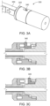
- FIGs. 3A-3C illustrate the proximal part of another example endoscope attachment coupler 330, in accordance with implementations of the disclosure.
- the attachment coupler 330 may be a female coupler that twists onto a male coupler 810 of an endoscope housing 310 and is locked in place by a slidable control 340 that functions similar to the locking screw 140 shown in Figures 1B-1D .
- the attachment coupler 330 includes a rotatable joint 320 that enables rotation of rigid attachment adapter 350 about its longitudinal axis, in a manner previously described. FIGs.
- 3B-3C depict a cross-sectional view showing a locking mechanism of coupler 330 that includes a slidable control 340 (e.g., embedded in the proximal part of coupler 330) that locks the attachment coupler 330 to the endoscope housing 310 by sliding into a groove 820 along the top edge of the male endoscope coupler 810.
- FIG. 3B shows the locking mechanism in an unlocked position.
- FIG. 3C shows the locking mechanism in a locked position.
- FIGs. 4A-4B illustrate a proximal part of another example endoscope attachment coupler 430, in accordance with implementations of the disclosure.
- the proximal aspect of the attachment coupler 430 may twist onto the male coupler 810 of an endoscope housing 410 and be locked into position by a lever 442 actuated (released) by a depressible button 440.
- the attachment coupler 430 includes a rotatable joint 420 that enables rotation of rigid attachment adapter 450 about its longitudinal axis, in a manner previously described.
- a depressible button 440 attaches to a lever arm 442 that may engage a groove 820 along the top edge of the male endoscope coupler 810.
- FIG. 4B depicts a cross-sectional view showing a locking mechanism of coupler 430 that locks rotatable joint 420 in place.
- FIG. 4B shows the locking mechanism in the unlocked position.
- the adapter may use any suitable mechanism (e.g., screw, slidable control, pressable control, magnetic, twist on spring tension, etc.) that may be actuated to lock the adapter onto the endoscope housing.
- any suitable mechanism e.g., screw, slidable control, pressable control, magnetic, twist on spring tension, etc.
- FIGs. 5A-5B depict an endoscope 500 to which an endoscope adapter may be coupled to, in accordance with implementations of the disclosure.
- the endoscope 500 includes a shaft 510, a connector 520 adjacent a proximal end of shaft 510, and an endoscope head and/or handle 530 adjacent the connector 520.
- Shaft 510 may rigid, flexible (e.g., bendable), removable, disposable, or it may be part rigid, flexible, or malleable (hybrid).
- shaft 510 may be threaded through a channel of an adapter 200 and connector 210 of adapter 200 may be secured to connector 520 of endoscope 500.
- adapter 200 is shown removably coupled to the endoscope 500 in FIG.
- any of aforementioned adapters may be removably coupled to the endoscope 500. It should be further appreciated that any of the aforementioned adapters may either include a rotatable joint or instead be attached to the endoscope in a fixed manner incapable of manual rotation along its longitudinal axis.
- the endoscope shaft (flexible, rigid, or hybrid) may in and of itself be detachable and re-attachable from the endoscope head or rigid attachment segment.
- Such removable shafts may be capable of receiving an adapter coupler or may instead already have an adapter configuration 200 as part of their shaft structure.
- Detachable shaft configurations of different sizes, shapes, profiles, rigidity, and attachment segment lengths with instrument attachment capabilities would permit single use, disposable sterilized shafts and custom configurations for instrument attachment depending on the surgical application.
- endoscope 500 may be removably coupled to a channel of an instrument (further discussed below), in a plurality of different lengthwise positions via rigid attachment segment 230, and/or a plurality of different circumferential positions via rotatable joint 220.
- adapter 200 includes a rotatable joint for manually rotating the endoscope for image orientation and/or positioning
- alternative implementations described below describe an adapter without a rotatable joint that may instead rely on digital image rotation.
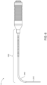
- FIG. 6 depicts an endoscope attachment adapter 650 removably coupled to an endoscope 600 with a flexible shaft 610.
- an angled distal part 640 of the adapter 650 causes the endoscope shaft 610 to bend 90 degrees after the adapter 650 is coupled to the endoscope.
- FIG. 7 depicts an endoscope attachment adapter 750 removably coupled to another endoscope 700 with a flexible shaft 710.
- This adapter causes the endoscope shaft to take on multiple bends, 720, 730.
- threading the flexible scope through a rigid or semi-rigid adapter with a single bend (adapter 650) or multiple bends (adapter 750) may be difficult.
- the distal segments of the rigid sleeve adapters (650, 750) may require relief slots along the radius of the bends to facilitate the threading of the scope through the adapter.
- FIG.8A shows an endoscope 800 with a twist-on male coupler 810 attached to the endoscope head 830.
- the coupler has a small groove or slot 820 that engages the locking mechanisms, previously described for the attached adapters.
- FIG. 8B shows an endoscope 850 that contains a rotatable ring 860 on the proximal part of the endoscope housing 870.
- the endoscope shaft 855 of endoscope 850 includes a non-rotatable adapter on the proximal part of endoscope shaft 855 that is coupled in a non-rotatable manner to the endoscope housing 870.
- the rotatable ring 860 may be used to digitally adjust an orientation of captured video/images in real time.
- the endoscope attachment adapter may be configured to be fixed in place as opposed to being capable of rotating about its longitudinal axis.
- the adapter may not include a rotatable joint (e.g., rotatable joint 120).
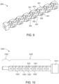
- FIG. 9 depicts one such example of a fixed endoscope attachment adapter 900.
- the rigid attachment segment is four-sided with a square cross section.
- the attachment mechanism is formed on multiple sides (e.g., two, three, or all four) of the rigid attachment segment of adapter 900.
- adapter 900 may still be used to couple an endoscope to an instrument channel in multiple circumferential positions by virtue of having the attachment segment formed on the rigid attachment segment.
- FIG. 10 depicts another example of a fixed endoscope attachment adapter 1000.
- adapter 1000 includes a connector 1010, rigid attachment segment 1020, and distal segment 1030.
- distal segment 1030 may be omitted.
- rigid attachment segment 1020 is four-sided with a square cross section.
- the attachment mechanism is formed on multiple sides (e.g., two, three, or all four) of rigid attachment segment 1020. That is, multiple grooves 1023 and multiple sections 1022, each of the sections 1022 having a recessed indentation or hole 1021, are formed on each of the multiple sides of segment 1020.
- Section 1030 may in some instances be configured to receive adapter sleeves for implementing attachment of the distal scope shaft to an instrument, permitting suction/irrigation for cleaning the endoscope tip, providing a conduit for electrical current to be delivered to the scope or instrument tip, etc.
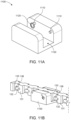
- FIG. 11A depicts an instrument housing 1100 that an endoscope attachment adapter (e.g., adapter 100) may be removably coupled to, in accordance with implementations of the disclosure.
- the instrument housing 1100 may be integrated near the top, on the side (e.g., Fig. 15 A-C ), or underneath the handle portion of an instrument or instrument shaft.
- the instrument housing 1100 may be part of a handle of an instrument such as a bipolar suction cautery, coblation wand, laryngeal forceps, sinus forceps, orthopedic articulating forceps, a laryngeal syringe gun, an endoscopic Eustachian tube balloon dilator, an endoscopic tracheal dilator, an endoscopic trans-oral esophageal balloon dilator, injection syringe, or some other instrument.
- Housing 1100 utilizes a top-loading ratchet mechanism to secure an adapter 100 to the instrument.
- an endoscope with a coupled adapter 100 may be removably coupled in a top-down manner by pushing down the proximal end of the endoscope shaft with the adapter (i.e., pushing down rigid attachment segment 130) into an open channel 1130 of housing 1100.
- housing 1100 includes an open channel 1130, ridges, pins, or protrusions 1110, and spring-loaded protrusion (e.g., spring-loaded ball) 1120.
- Rigid attachment segment 130 may be secured in place by i) pushing it down into open channel 1130 along openings of two adjacent grooves 133; and ii) sliding rigid attachment segment 130 relative to open channel 1100 to position each ridge 1110 within a respective groove 133 of the adjacent grooves 133 such that protruding portions 138 of sections 131 adjacent the grooves 133 prevent lifting of the rigid attachment segment 130 (i.e., they block ridges 1110).
- FIG. 11B shows a housing 1100 removably coupled to a rigid attachment segment 130 of an adapter 100.
- the positions of spring-loaded protrusion 1120 and indentation/hole 132 may be reversed, i.e., the indentation 132 is part of the housing 1100 and the spring-loaded protrusion is part of the adapter 100.
- the endoscope may be quickly secured within the instrument housing 1100 at a particular lengthwise position without the requirement of an elongated open channel 1130.
- This type of attachment mechanism may eliminate any rocking of the endoscope shaft within the open channel 1100 and allow for shorting of the open channel when compared to the depressible button/lever mechanism previously described in US Patent No. 10,512,391 .
- the top-loading ratchet mechanism described herein provides a quick and simple means for securing an endoscope to an instrument.
- Coupling, uncoupling, and/or repositioning an endoscope within the instrument is simply a matter of lifting down/up and sliding such that ridges 1110 are inserted into a particular set of grooves 133 and spring-loaded protrusion 1120 is secured within a particular indentation 1132.
- FIGs. 12A-12D illustrate another example of an instrument housing 1200 that an endoscope attachment adapter (e.g., adapter 100) may be removably coupled to, in accordance with implementations of the disclosure.
- the interior surface of housing 1200 includes an open channel 1230, ridges or protrusions 1210, and, in this instance, multiple spring-loaded protrusions (e.g., spring-loaded balls) 1220.
- Rigid attachment segment 130 may be secured in place by i) pushing it down into open channel 1230 along openings of two adjacent grooves 133; and ii) sliding rigid attachment segment 130 relative to open channel 1230 to position each ridge 1210 within a respective groove 133 of the adjacent grooves 133 such that protruding portions 138 of sections 131 adjacent the grooves 133 prevent lifting of the rigid proximal attachment segment 130 (i.e., they block ridges 1210). Additionally, when the assembly is slid, spring-loaded protrusions 1220 may be secured within an indentation/hole 132 of the sections 131 positioned next to the two grooves 133.
- FIG. 13A illustrates an H-channel adapter 1300 that may be removably coupled to the attachment segment of an endoscope shaft, endoscope attachment adapter (e.g., adapter 100), and/or endoscope instrument tools, in accordance with implementations of the disclosure.
- H-channel adapter 1300 includes an upper open channel 1310 for removably coupling H-channel adapter 1300 to endoscope attachment adapter 100, and a lower open channel 1320, opposite the upper open channel 1310, for removably coupling H-channel adapter 1300 to endoscope instrument tools.
- the interior surface of the upper open channel 1310 includes ridges or protrusions 1312, and spring-loaded protrusions (e.g., spring-loaded balls) 1311.
- Rigid attachment segment 130 may be secured in place by i) pushing it down into upper open channel 1310 along openings of two adjacent grooves 133; and ii) sliding rigid attachment segment 130 relative to open channel 1310 to position each ridge 1312 within a respective groove 133 of the adjacent grooves 133 such that protruding portions 138 of sections 131 adjacent the grooves 133 prevent lifting of the rigid attachment segment 130 (i.e., they block ridges 1312).
- FIG. 13B depicts an example of H-channel adapter 1300 attached to a distal end of an endoscope attachment adapter 1350.
- the interior surface of the lower open channel 1320 includes side rails 1321 for slidably coupling an instrument tool.
- an instrument tool For example, forceps, suctions, graspers, culture tools, fasteners, staplers, or some other instrument tool contain side grooves or longitudinal slots to engage side rails 1321 allowing attachment to the underside of the endoscope via lower open channel 1320.
- a sliding mechanism is illustrated coupling lower open channel 1320 to an instrument tool, it should be appreciated that any suitable coupling mechanism may be utilized.
- H-channel adapter 1300 that may be removably attached to an endoscope attachment adapter (e.g., adapter 100) in a convenient lengthwise position
- instrument tools may be attached in a suitable position underneath the endoscope with the adapter 100 and H-channel adapter 1300.
- endoscope attachment adapter e.g., adapter 100
- instrument tools may be attached in a suitable position underneath the endoscope with the adapter 100 and H-channel adapter 1300.
- multiple instrument channels offset from one another into the same adapter multiple instruments could be simultaneously attached to the endoscope at the same time. This would be helpful when performing rigid laryngoscopy when there may be need for a forceps, suction, laser, and endoscope all working together at the same time through a single rigid tube.
- other adapters may be used that have two or more channels that are offset 90 degrees from one another in an either side by side, or otherwise offset manner.
- FIG. 14A depicts an endoscope 1410 coupled to an instrument 1430 via an H-channel adapter 1600 in accordance with implementations of the disclosure.
- the distal shaft 1420 of the instrument 1430 is shown to extend underneath the endoscope shaft 1440.
- the proximal shaft 1445 of instrument 1430 connects to endoscope 1410 via H-channel adapter 1600 and a rigid attachment segment on the shaft of the endoscope (e.g., rigid attachment segment 130 of adapter 100) as discussed above.
- the rigid attachment segment may be part of an adapter (e.g., adapter 100) that couples to a proximal part of the shaft of the endoscope 1410 or integrated into a proximal part of the shaft of the endoscope 1410.
- FIG. 14B depicts an endoscope 1480 coupled to an instrument 1450 and instrument shaft 1460 in accordance with implementations of the disclosure.
- a top portion of instrument 1450 includes an open channel that couples to endoscope 1410 via a rigid attachment segment on the shaft of the endoscope (e.g., rigid attachment segment 130 of adapter 100) as discussed above.
- the rigid attachment segment may be part of an adapter (e.g., adapter 100) that couples to a proximal part of the shaft of the endoscope 1480 or integrated into a proximal part of the shaft of the endoscope 1480.
- instrument 1450 includes a handle mechanism 1455 to actuate tool tip 1470 attached to instrument shaft 1460.
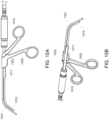
- FIGs. 15A-15C depict an assembly including a forceps instrument 1520 removably coupled to an endoscope 1510 via an endoscope attachment adapter 1511, in accordance with implementations of the disclosure.
- FIG. 15A depicts a side view of the assembly
- FIG. 15B depicts a perspective view of the assembly
- FIG. 15C depicts a frontal view of the assembly.
- the endoscope attachment adapter 1511 may be secured at a proximal end of the shaft of endoscope 1510.
- the forceps instrument 1520 includes a handle, including an integrated instrument housing 1522 that endoscope attachment adapter 1511 is removably coupled to, and a distal tool portion 1521.
- the instrument housing channel 1522 is oriented to the side rather than on the top of the instrument 1520.
- the endoscope attachment adapter 1511 and the instrument housing 1522 may be structured in a manner similar to that previously described above.
- a distal portion 1512 of endoscope 1510 may be conveniently positioned underneath and adjacent to tool portion 1521 of forceps instrument 1520 to capture a suitable image of a patient's cavity.
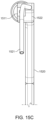
- FIGs. 16A-16B illustrates an H-channel adapter 1600 that may be removably coupled to an endoscope attachment adapter (e.g., adapter 100) and endoscope instrument tools, in accordance with implementations of the disclosure.
- H-channel adapter 1600 includes an upper open channel 1610 for removably coupling H-channel adapter 1600 to an endoscope attachment adapter or to an instrument, and a lower open channel 1620, opposite the upper open channel 1610, for removably coupling H-channel adapter 1600 to an endoscope attachment adapter or to an instrument.
- the interior surface of the upper open channel 1610 includes ridges or protrusions 1612, and a spring-loaded protrusion (e.g., spring-loaded ball) 1611.
- Rigid attachment segment 130 may be secured in place by i) pushing it down into upper open channel 1610 along openings of two adjacent grooves 133; and ii) sliding rigid attachment segment 130 relative to open channel 1610 to position each ridge 1612 within a respective groove 133 of the adjacent grooves 133 such that protruding portions 138 of sections 131 adjacent the grooves 133 prevent lifting of the rigid attachment segment 130 (i.e., they block ridges 1612).
- spring-loaded protrusion 1611 may be secured within an indentation/hole 132 of the section 131 positioned next to the two grooves 133.
- the interior surface of the lower open channel 1620 includes ridges or protrusions 1612, and a spring-loaded protrusion 1611.
- one or both of channels 1610 and 1620 may include at least two spring-loaded protrusions 1611.
- one or both of channels 1610 and 1620 may include an indentation or non-spring loaded protrusion in place of spring-load protrusion 1611.
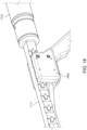
- FIGs. 17-18 depict an H-channel adapter 1600 used to removably couple an endoscope 1710 and forceps instrument 1720, in accordance with implementations of the disclosure.
- FIG. 17 shows a side view.
- FIG. 18 shows a perspective view.
- an endoscope attachment adapter 100 is coupled to endoscope 1710.
- the upper open channel 1610 of H-channel adapter 1600 is removably coupled to rigid attachment segment 130 of endoscope attachment adapter 100.
- the lower open channel 1620 of H-channel adapter 1600 is removably coupled to a handle portion of forceps instrument 1720.
- H-channel adapter 1600 to removably couple endoscope 1710 to forceps instrument 1720, a distal portion 1711 of endoscope 1710 may be conveniently positioned adjacent tool portion 1721 of forceps instrument 1720 to capture a suitable image of a patient's cavity.
- a variety of other instruments may be removably coupled to the lower channel 1620 of H-channel adapter 1600.
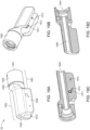
- FIGs. 19A-19D depict another implementation of an endoscope attachment adapter 1900, in accordance with implementations of the disclosure.
- FIGs. 19A-19B show different perspective views of the adapter 1900
- FIGs. 19C-19D show different cross-sectional views of adapter 1900.
- Adapter 1900 include a proximal part 1901 including an adapter connector 1930, and a distal part 1902 including a channel housing 1920 configured to couple to an instrument.
- adapter 1900 At a proximal end of adapter 1900 is an opening 1941 through connector 1930. At a distal end of adapter 100 is an opening 1942 through distal part 1902. From opening 1941 to opening 1942 is a channel 1940 that extends through connector 1930 and distal part 1902. To separate it from channel housing 1920, the channel 1940 may be closed. A shaft of an endoscope may be threaded through channel 1940, starting at opening 1941 and moving through opening 1942. Once the endoscope shaft is threaded through the channel of adapter 1900, adapter 1900 may be secured at a proximal end of the endoscope shaft by removably coupling adapter connector 1930 (e.g., to an endoscope connector).
- adapter connector 1930 e.g., to an endoscope connector
- the two connectors may be secured and locked via one or more suitable coupling mechanisms, including a twist lock mechanism, an interference fit, a suction fit, a magnetic mechanism, and/or some other mechanism and then locked via mechanisms previously described.
- a locking screw may be used to secure the connector 1930 to a male coupler of an endoscope.
- connector 1930 is illustrated as a female coupler configured to connect to a male coupler (e.g., at a proximal end of an endoscope shaft), in other implementations connector 1930 may be a male coupler configured to connect to a female coupler (e.g., at a proximal end of an endoscope shaft).
- Adapter 1900 includes a rotatable, circular joint 1950 that enables rotation of adapter 1900 about its longitudinal axis (e.g., rotation of rigid distal part 1902 relative to connector 1930).
- the joint 1950 may be fused to an a proximal end of the rigid distal part 1902, and it may be structured and function in a manner similar to that discussed above with reference to joint 120. In this manner, an endoscope may be removably coupled to adapter 1900 in a plurality of different circumferential positions.
- Channel housing 1920 of the distal part 1902 is positioned below channel 1940.
- Channel housing 1920 includes an open channel 1910.
- An interior surface of open channel 1910 includes ridges or protrusions 1912, and a spring-loaded protrusion (e.g., spring-loaded ball) 1911.
- Channel housing 1920 may be coupled to a rigid attachment segment having a structure similar to that described above with reference to rigid attachment segment 130.
- FIGs. 20A-20B depict an endoscope attachment adapter 1900 used to removably couple an endoscope 2010 and forceps instrument 2040, in accordance with implementations of the disclosure.
- FIG. 20A shows a perspective view.
- FIG. 20B shows a side view.
- FIG. 21 depicts a side view of forceps instrument 2040.
- adapter 1900 is removably coupled to endoscope 1900 by threading shaft 2011 of endoscope 2010 through channel 1940 (starting from opening 1941, and moving through opening 1942), and securing coupling adapter connector 1930 to endoscope 1900.
- connector 1930 may be secured near a proximal end of shaft 2011 in a similar manner to that discussed above with reference to coupler 110.
- Channel housing 1920 removably couples adapter 1900 to forceps instrument 2040 via open channel 1910 of adapter 1900.
- the open channel 1910 of adapter 1900 is removably coupled to a top of a handle portion of forceps instrument 2040, which includes grooves 2042 and indentation 2043 on its surface.
- the forceps instrument 2040 may be removably secured in place to open channel 1910 by i) pushing it into open channel 1910 along openings of the two grooves 2042; and ii) sliding the forceps handle relative to open channel 1910 to position each ridge 1912 within a respective groove 2042. Additionally, after sliding, spring-loaded protrusion 1911 may be secured within indentation/hole 2043.
- adapter 1900 By virtue of using adapter 1900 to removably couple endoscope 2010 to forceps instrument 2040, a distal portion of endoscope 2010 may be conveniently positioned adjacent tool portion 2041 of forceps instrument 2040 to capture a suitable image of a patient's cavity. Additionally, adapter 1900 effectually combines the upper channel of adapter 1600 with the rotational capability of adapter 100 while preserving the lower channel for instrument attachment.
- FIGs. 20A-20B depict an endoscope attachment adapter 1900 used to removably couple an endoscope 2010 and forceps instrument 2040
- adapter 1900 may couple a variety of different instruments to an endoscope, assuming the instruments have a coupling mechanism compatible with the attachment mechanism of open channel 1910.
- FIG. 22 shows a suction instrument 2200 that may removably couple to adapter 1900 via open channel 1910.
- the suction instrument 2200 includes a handle portion and a tool portion 2241. Incorporated into a surface of a top of the handle portion are grooves 2242 and indentation 2243, which may be used to couple instrument 2200 to open channel 1910.
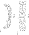
- FIG. 23 depicts a portion of an endoscope shaft or attachment adapter 2300 that is rectangular and includes hinges 2310.
- hinges 2310 utilize an a joint that enables pivoting or rotation of portions of adapter 2300 about a single plane.
- FIG. 24 depicts a portion of an endoscope attachment adapter 2400 that is rectangular and includes a ball and socket hinge 2410.
- ball and socket hinge 2410 enables pivoting or rotation of portions of adapter 2400 about both a horizontal plane and vertical plane.
- FIGs. 23-24 illustrate two examples hinge joints that may be utilized, it should be appreciated that other suitable hinge joints may be used.
- the head of the endoscope may be angled out of the way (e.g., 10-90 degrees) of the instrument. This may enable attachment of the endoscope to an instrument or device that itself must remain straight to function.
- the adapter may be hinged in two or three locations to bend the scope around the head of the instrument. Additionally, the hinged segments may enable attachment to various contours of instrumentation.
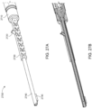
- FIGs. 25A-25C depict another embodiment of an endoscope attachment adapter 2500, in accordance with implementations of the disclosure.
- FIGs. 25A-25B illustrate a perspective view of adapter 2500
- FIG. 25C illustrates a cross-sectional view of adapter 2500.
- Adapter 2500 includes a coupler 2510, a rotatable joint 2520, a hinge joint 2540, and a rigid attachment segment 2530.
- adapter 2500 At a proximal end of adapter 2500 is an opening 2511 through connector 2510. At a distal end of adapter 2500 is an opening 2541.
- the opening 2541 may begin at a distal end of rigid attachment segment 2530. From opening 2511 to opening 2541 is a channel 2575 that extends through the length of adapter 2500.
- a flexible shaft of an endoscope may be threaded through channel 2575, starting at opening 2511 and moving through opening 2541.
- adapter 2500 Once the endoscope shaft is threaded through the channel of adapter 2500, adapter 2500 may be secured at a proximal end of the endoscope shaft by removably coupling adapter connector 2510 (e.g., to an endoscope connector). The two connectors may be secured in a manner similar to that described above with reference to connector 110 of adapter 100.
- Rigid attachment segment 2530 is four-sided with a square cross section. In other implementations, rigid attachment segment 2530 may have a different rectangular cross section or a circular cross-section. On the surface of one of the four sides of segment 2530 are formed a plurality of grooves/slots 2533 and a plurality of sections 2531 that protrude relative to the grooves 2533, each of the sections 2531 having a recessed indentation or hole 2532. Rigid attachment segment 2530 may be used to couple the adapter 2500 to an instrument in a manner similar to that discussed above with reference to adapter 100.
- a rotatable joint 2520 positioned between hinge joint 2540 and coupler 2510 enables rotation of adapter 2500 about its longitudinal axis.
- Rotatable joint 2520 may be implemented in a manner similar to that discussed above with reference to rotatable joint 120.
- the hinge joint 2540 coupled between rigid attachment segment 2530 and coupler 2510 enables additional angling of rigid attachment segment 2530.
- additional degrees of freedom in positioning adapter 2500 are provided. Adding several hinged joints 2540 in series allows for even greater changes in attachment shaft contour.
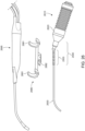
- Fig. 26 depicts a clip-on instrument adapter 2680 that connects to a hinged attachment adapter 2500 coupled to endoscope 2610 which is comprised of endoscope housing 2620 and flexible shaft 2630.
- Instrument adapter 2680 contains a channel housing 2682 that could be used to attach an endoscope attachment segment 2503.
- instrument adapter 2680 includes one or more clips 2681 that may attach in various configurations to instrument housings and instrument configurations that do not have the necessary slot and groove configuration for direct attachment in the manner described above. For example, a body of ablation wand 2695 may be snapped on to clips 2681 in a specific position.
- the clips 2681 may be manufactured to attach to different handles of different instruments of different manufacturers.
- this embodiment shows clips, other manners of attachment could also be used such as magnets, straps, clamps, screws, suction, cables, etc.
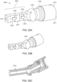
- FIGs. 27A-27B show perspective and cross-sectional views of an endoscope attachment adapter 2700 with integrated cannula that may be used to flush/clean the tip of an endoscope.
- a suction/irrigation port 2720 would connect proximally via irrigation or suction tubing to a suction/irrigation pump activated by either foot or handheld control.
- the cannula adapter may slide over a rigid, flexible, or hybrid endoscope shaft and connect via connector 2710 to the endoscope coupler ( Fig. 8A , 810) located on the distal endoscope housing, and may have rotation capabilities.
- the distal segment of the cannula i.e., that portion of the cannula that extends distal from the rectangular attachment portion 2730 of the adapter, may also be rigid, flexible, or hybrid.
- FIG. 28 depicts a corkscrew shaped instrument shaft having a proximal end 2811 and distal end 2812.
- This shape may allow an endoscope shaft having proximal end 2801 positioned above instrument shaft proximal end 2811 to pass underneath the instrument shaft (e.g., at segment 2890) such that the distal end 2802 of the endoscope shaft is below distal end 2812 of the instrument shaft, allowing visualization by the endoscope of a tool tip of the instrument shaft from below rather than above the instrument shaft in a manner similar to the distal configuration of Figs. 15A and 15B .
- a semi-rigid malleable endoscope shaft adapter that can be bent or molded around an instrument or instrument shaft in a reversible manner is also envisioned.
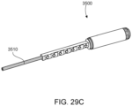
- FIGs. 29A-29C depict one example of a an endoscope 3500 having a malleable endoscope shaft 3510.
- the malleable endoscope shaft 3510 may be molded, bent, or otherwise shaped in a reversible manner.
- the adapter, pictured in FIG. 29C may also be malleable.
- a flexible-rigid hybrid endoscope e.g., an endoscope having a shaft with a flexible distal end and a rigid proximal end
- a rigid endoscope e.g., an endoscope having a rigid shaft
- an endoscope shaft with an integrated proximal attachment segment similar in structural features to adapter 100, adapter 200, adapter 900, adapter 1000, adapter 1900, adapter 2500, or adapter 2700.
- the endoscope connector e.g., 110 of the adapter may be excluded.
- the proximal segment of the endoscope shaft may have a rectangular cross section, similar to the one described above for adapter 100, on which on at least one of the four sides are formed a plurality of grooves/slots 133 and a plurality of sections 131, each of the sections 131 having a recessed indentation or hole 132.
- the benefits of this top-down ratchet attachment design may be realized by directly integrating them into the proximal attachment segment of the endoscope shaft.
- the endoscope shaft may be configured to rotate about a rotatable joint.
- the endoscope shaft may be configured to couple to instrument housing 1100, instrument housing 1200, or H-channel adapter 1300, or H-channel adapter 1600.
- proximal attachment segment of the endoscope shaft may itself include one or more hinges, allowing for changes in the shape of the endoscope shaft to accommodate varying shapes and contours of surgical instruments without allowing for flaccidity which would destabilize the scope when attached to an instrument.
- the endoscopes, attachment mechanisms, and instruments described herein may be utilized in any suitable application.
- they may be utilized in Otorhinolaryngologic (Ear, nose, and throat, ENT) surgical applications. They may also be utilized in other surgical and medical specialties such as general surgery, gastroenterology, pulmonology, urology, plastic surgery, neurosurgery, OB/GYN, and orthopedics for applications such as surgical stapling, tissue ablation, arthroscopic surgery, etc.
- Commercial, non-surgical, applications for the technology disclosed herein are also applicable.
- substantially and “about” used throughout this disclosure, including the claims, are used to describe and account for small fluctuations, such as due to variations in processing. For example, they can refer to less than or equal to ⁇ 5%, such as less than or equal to ⁇ 2%, such as less than or equal to ⁇ 1%, such as less than or equal to ⁇ 0.5%, such as less than or equal to ⁇ 0.2%, such as less than or equal to ⁇ 0.1%, such as less than or equal to ⁇ 0.05%.
- module does not imply that the components or functionality described or claimed as part of the module are all configured in a common package. Indeed, any or all of the various components of a module, whether control logic or other components, can be combined in a single package or separately maintained and can further be distributed in multiple groupings or packages or across multiple locations.
Landscapes
- Health & Medical Sciences (AREA)
- Life Sciences & Earth Sciences (AREA)
- Surgery (AREA)
- Engineering & Computer Science (AREA)
- Nuclear Medicine, Radiotherapy & Molecular Imaging (AREA)
- Medical Informatics (AREA)
- Optics & Photonics (AREA)
- Pathology (AREA)
- Radiology & Medical Imaging (AREA)
- Physics & Mathematics (AREA)
- Veterinary Medicine (AREA)
- Biomedical Technology (AREA)
- Heart & Thoracic Surgery (AREA)
- Biophysics (AREA)
- Molecular Biology (AREA)
- Animal Behavior & Ethology (AREA)
- General Health & Medical Sciences (AREA)
- Public Health (AREA)
- Signal Processing (AREA)
- Mechanical Engineering (AREA)
- Rehabilitation Therapy (AREA)
- Endoscopes (AREA)
- Instruments For Viewing The Inside Of Hollow Bodies (AREA)
Applications Claiming Priority (3)
| Application Number | Priority Date | Filing Date | Title |
|---|---|---|---|
| US202063092733P | 2020-10-16 | 2020-10-16 | |
| PCT/US2021/055249 WO2022082022A2 (en) | 2020-10-16 | 2021-10-15 | Endoscope attachment mechanisms and methods of use |
| EP21806093.7A EP4228491B1 (de) | 2020-10-16 | 2021-10-15 | Endoskopbefestigungsmechanismen und verfahren zur verwendung |
Related Parent Applications (1)
| Application Number | Title | Priority Date | Filing Date |
|---|---|---|---|
| EP21806093.7A Division EP4228491B1 (de) | 2020-10-16 | 2021-10-15 | Endoskopbefestigungsmechanismen und verfahren zur verwendung |
Publications (2)
| Publication Number | Publication Date |
|---|---|
| EP4574013A2 true EP4574013A2 (de) | 2025-06-25 |
| EP4574013A3 EP4574013A3 (de) | 2025-08-13 |
Family
ID=78592941
Family Applications (2)
| Application Number | Title | Priority Date | Filing Date |
|---|---|---|---|
| EP25174554.3A Pending EP4574013A3 (de) | 2020-10-16 | 2021-10-15 | Endoskopbefestigungsmechanismen und verfahren zur verwendung |
| EP21806093.7A Active EP4228491B1 (de) | 2020-10-16 | 2021-10-15 | Endoskopbefestigungsmechanismen und verfahren zur verwendung |
Family Applications After (1)
| Application Number | Title | Priority Date | Filing Date |
|---|---|---|---|
| EP21806093.7A Active EP4228491B1 (de) | 2020-10-16 | 2021-10-15 | Endoskopbefestigungsmechanismen und verfahren zur verwendung |
Country Status (8)
| Country | Link |
|---|---|
| US (3) | US11529040B2 (de) |
| EP (2) | EP4574013A3 (de) |
| JP (1) | JP2023545495A (de) |
| CN (1) | CN220309105U (de) |
| AU (1) | AU2021361124A1 (de) |
| CA (1) | CA3195775A1 (de) |
| ES (1) | ES3033069T3 (de) |
| WO (1) | WO2022082022A2 (de) |
Families Citing this family (6)
| Publication number | Priority date | Publication date | Assignee | Title |
|---|---|---|---|---|
| EP4157059A4 (de) * | 2020-05-29 | 2024-09-04 | Noah Medical Corporation | Verfahren und systeme für einwegendoskope |
| US20240065533A1 (en) * | 2022-08-30 | 2024-02-29 | Integrated Endoscopy, Inc. | Endoscope with interchangeable cannula adapter |
| CN116138713B (zh) * | 2023-02-28 | 2025-06-06 | 湖南省华芯医疗器械有限公司 | 一种内窥镜的适配器、手柄及内窥镜 |
| CN116211217B (zh) * | 2023-03-13 | 2025-06-06 | 湖南省华芯医疗器械有限公司 | 一种内窥镜适配器、内窥镜及安装方法 |
| WO2025085936A1 (en) * | 2023-10-20 | 2025-04-24 | The Regents Of The University Of Colorado, A Body Corporate | Articulating endoscope and methods of using the same |
| WO2025117855A1 (en) | 2023-11-29 | 2025-06-05 | Resnent, Llc | Modular endoscope assembly |
Citations (1)
| Publication number | Priority date | Publication date | Assignee | Title |
|---|---|---|---|---|
| US10512391B2 (en) | 2017-04-20 | 2019-12-24 | Resnent, Llc | Flexible-rigid hybrid endoscope and instrument attachments |
Family Cites Families (16)
| Publication number | Priority date | Publication date | Assignee | Title |
|---|---|---|---|---|
| US5156141A (en) * | 1991-03-11 | 1992-10-20 | Helmut Krebs | Connector for coupling an endoscope to a video camera |
| US5797836A (en) * | 1995-06-07 | 1998-08-25 | Smith & Nephew, Inc. | Endoscope with relative rotation and axial motion between an optical element and an imaging device |
| JP2003204920A (ja) | 2002-01-11 | 2003-07-22 | Olympus Optical Co Ltd | 挿入補助具 |
| JP4142369B2 (ja) | 2002-08-07 | 2008-09-03 | オリンパス株式会社 | 内視鏡処置システム |
| US7431694B2 (en) * | 2003-05-16 | 2008-10-07 | Ethicon Endo-Surgery, Inc. | Method of guiding medical devices |
| US7758497B2 (en) * | 2003-06-20 | 2010-07-20 | Contura A/S | Endoscopic attachment device |
| JP2005296412A (ja) * | 2004-04-13 | 2005-10-27 | Olympus Corp | 内視鏡治療装置 |
| US20070225562A1 (en) * | 2006-03-23 | 2007-09-27 | Ethicon Endo-Surgery, Inc. | Articulating endoscopic accessory channel |
| US20080058595A1 (en) * | 2006-06-14 | 2008-03-06 | Snoke Phillip J | Medical device introduction systems and methods |
| US7976458B2 (en) * | 2006-12-05 | 2011-07-12 | Ethicon Endo-Surgery, Inc. | Independent articulating accessory channel |
| US8562512B2 (en) * | 2007-05-09 | 2013-10-22 | Microline Surgical, Inc. | Endoscopic tool assembly |
| CN104349734B (zh) * | 2012-05-25 | 2016-09-28 | 富士胶片株式会社 | 内窥镜手术装置及外套管 |
| DE102015113424A1 (de) * | 2015-08-14 | 2017-02-16 | Invendo Medical Gmbh | Handgriff eines Endoskops |
| WO2017205468A1 (en) * | 2016-05-24 | 2017-11-30 | Civco Medical Instruments Co., Inc. | Low profile endocavity needle guides |
| JP6625746B2 (ja) * | 2016-06-30 | 2019-12-25 | 富士フイルム株式会社 | 超音波内視鏡、及びその製造方法 |
| PL3494861T3 (pl) * | 2017-12-05 | 2024-05-13 | Erbe Elektromedizin Gmbh | Urządzenie z elementem prowadzącym kanał roboczy |
-
2021
- 2021-10-15 CA CA3195775A patent/CA3195775A1/en active Pending
- 2021-10-15 CN CN202190000928.3U patent/CN220309105U/zh active Active
- 2021-10-15 US US17/503,004 patent/US11529040B2/en active Active
- 2021-10-15 EP EP25174554.3A patent/EP4574013A3/de active Pending
- 2021-10-15 EP EP21806093.7A patent/EP4228491B1/de active Active
- 2021-10-15 JP JP2023522970A patent/JP2023545495A/ja active Pending
- 2021-10-15 WO PCT/US2021/055249 patent/WO2022082022A2/en not_active Ceased
- 2021-10-15 US US17/503,044 patent/US11478130B2/en active Active
- 2021-10-15 AU AU2021361124A patent/AU2021361124A1/en active Pending
- 2021-10-15 ES ES21806093T patent/ES3033069T3/es active Active
-
2022
- 2022-12-09 US US18/078,370 patent/US20230103718A1/en active Pending
Patent Citations (1)
| Publication number | Priority date | Publication date | Assignee | Title |
|---|---|---|---|---|
| US10512391B2 (en) | 2017-04-20 | 2019-12-24 | Resnent, Llc | Flexible-rigid hybrid endoscope and instrument attachments |
Also Published As
| Publication number | Publication date |
|---|---|
| AU2021361124A1 (en) | 2023-06-08 |
| ES3033069T3 (en) | 2025-07-30 |
| US20230103718A1 (en) | 2023-04-06 |
| WO2022082022A3 (en) | 2022-06-16 |
| EP4228491C0 (de) | 2025-05-07 |
| US20220117470A1 (en) | 2022-04-21 |
| EP4574013A3 (de) | 2025-08-13 |
| WO2022082022A8 (en) | 2023-05-11 |
| EP4228491A2 (de) | 2023-08-23 |
| US11529040B2 (en) | 2022-12-20 |
| WO2022082022A2 (en) | 2022-04-21 |
| US20220117465A1 (en) | 2022-04-21 |
| AU2021361124A9 (en) | 2024-10-24 |
| CN220309105U (zh) | 2024-01-09 |
| EP4228491B1 (de) | 2025-05-07 |
| CA3195775A1 (en) | 2022-04-21 |
| JP2023545495A (ja) | 2023-10-30 |
| US11478130B2 (en) | 2022-10-25 |
Similar Documents
| Publication | Publication Date | Title |
|---|---|---|
| US11478130B2 (en) | Endoscope with integrated attachment mechanisms and methods of use | |
| US12232911B2 (en) | Instrument holder | |
| AU2010241834B2 (en) | Adaptor for an endoscope | |
| US11986161B2 (en) | Detachable endoscope shaft | |
| HK40099299B (en) | Endoscope attachment mechanisms and methods of use | |
| HK40099299A (en) | Endoscope attachment mechanisms and methods of use | |
| McCarthy | Instrumentation for endoscopy | |
| US11737660B2 (en) | Articulating cannula with endoscope attachment |
Legal Events
| Date | Code | Title | Description |
|---|---|---|---|
| PUAI | Public reference made under article 153(3) epc to a published international application that has entered the european phase |
Free format text: ORIGINAL CODE: 0009012 |
|
| STAA | Information on the status of an ep patent application or granted ep patent |
Free format text: STATUS: THE APPLICATION HAS BEEN PUBLISHED |
|
| AC | Divisional application: reference to earlier application |
Ref document number: 4228491 Country of ref document: EP Kind code of ref document: P |
|
| AK | Designated contracting states |
Kind code of ref document: A2 Designated state(s): AL AT BE BG CH CY CZ DE DK EE ES FI FR GB GR HR HU IE IS IT LI LT LU LV MC MK MT NL NO PL PT RO RS SE SI SK SM TR |
|
| PUAL | Search report despatched |
Free format text: ORIGINAL CODE: 0009013 |
|
| AK | Designated contracting states |
Kind code of ref document: A3 Designated state(s): AL AT BE BG CH CY CZ DE DK EE ES FI FR GB GR HR HU IE IS IT LI LT LU LV MC MK MT NL NO PL PT RO RS SE SI SK SM TR |
|
| RIC1 | Information provided on ipc code assigned before grant |
Ipc: A61B 1/00 20060101AFI20250708BHEP |