EP4573997A1 - Vacuum cleaner nozzle - Google Patents
Vacuum cleaner nozzle Download PDFInfo
- Publication number
- EP4573997A1 EP4573997A1 EP23865925.4A EP23865925A EP4573997A1 EP 4573997 A1 EP4573997 A1 EP 4573997A1 EP 23865925 A EP23865925 A EP 23865925A EP 4573997 A1 EP4573997 A1 EP 4573997A1
- Authority
- EP
- European Patent Office
- Prior art keywords
- agitator
- connection pipe
- nozzle
- cleaner
- ground
- Prior art date
- Legal status (The legal status is an assumption and is not a legal conclusion. Google has not performed a legal analysis and makes no representation as to the accuracy of the status listed.)
- Pending
Links
Images



Classifications
-
- A—HUMAN NECESSITIES
- A47—FURNITURE; DOMESTIC ARTICLES OR APPLIANCES; COFFEE MILLS; SPICE MILLS; SUCTION CLEANERS IN GENERAL
- A47L—DOMESTIC WASHING OR CLEANING; SUCTION CLEANERS IN GENERAL
- A47L5/00—Structural features of suction cleaners
- A47L5/12—Structural features of suction cleaners with power-driven air-pumps or air-compressors, e.g. driven by motor vehicle engine vacuum
- A47L5/22—Structural features of suction cleaners with power-driven air-pumps or air-compressors, e.g. driven by motor vehicle engine vacuum with rotary fans
- A47L5/24—Hand-supported suction cleaners
- A47L5/26—Hand-supported suction cleaners with driven dust-loosening tools
-
- A—HUMAN NECESSITIES
- A47—FURNITURE; DOMESTIC ARTICLES OR APPLIANCES; COFFEE MILLS; SPICE MILLS; SUCTION CLEANERS IN GENERAL
- A47L—DOMESTIC WASHING OR CLEANING; SUCTION CLEANERS IN GENERAL
- A47L9/00—Details or accessories of suction cleaners, e.g. mechanical means for controlling the suction or for effecting pulsating action; Storing devices specially adapted to suction cleaners or parts thereof; Carrying-vehicles specially adapted for suction cleaners
-
- A—HUMAN NECESSITIES
- A47—FURNITURE; DOMESTIC ARTICLES OR APPLIANCES; COFFEE MILLS; SPICE MILLS; SUCTION CLEANERS IN GENERAL
- A47L—DOMESTIC WASHING OR CLEANING; SUCTION CLEANERS IN GENERAL
- A47L9/00—Details or accessories of suction cleaners, e.g. mechanical means for controlling the suction or for effecting pulsating action; Storing devices specially adapted to suction cleaners or parts thereof; Carrying-vehicles specially adapted for suction cleaners
- A47L9/009—Carrying-vehicles; Arrangements of trollies or wheels; Means for avoiding mechanical obstacles
-
- A—HUMAN NECESSITIES
- A47—FURNITURE; DOMESTIC ARTICLES OR APPLIANCES; COFFEE MILLS; SPICE MILLS; SUCTION CLEANERS IN GENERAL
- A47L—DOMESTIC WASHING OR CLEANING; SUCTION CLEANERS IN GENERAL
- A47L9/00—Details or accessories of suction cleaners, e.g. mechanical means for controlling the suction or for effecting pulsating action; Storing devices specially adapted to suction cleaners or parts thereof; Carrying-vehicles specially adapted for suction cleaners
- A47L9/02—Nozzles
- A47L9/04—Nozzles with driven brushes or agitators
- A47L9/0461—Dust-loosening tools, e.g. agitators, brushes
- A47L9/0466—Rotating tools
- A47L9/0477—Rolls
-
- A—HUMAN NECESSITIES
- A47—FURNITURE; DOMESTIC ARTICLES OR APPLIANCES; COFFEE MILLS; SPICE MILLS; SUCTION CLEANERS IN GENERAL
- A47L—DOMESTIC WASHING OR CLEANING; SUCTION CLEANERS IN GENERAL
- A47L9/00—Details or accessories of suction cleaners, e.g. mechanical means for controlling the suction or for effecting pulsating action; Storing devices specially adapted to suction cleaners or parts thereof; Carrying-vehicles specially adapted for suction cleaners
- A47L9/02—Nozzles
- A47L9/04—Nozzles with driven brushes or agitators
- A47L9/0461—Dust-loosening tools, e.g. agitators, brushes
- A47L9/0488—Combinations or arrangements of several tools, e.g. edge cleaning tools
-
- A—HUMAN NECESSITIES
- A47—FURNITURE; DOMESTIC ARTICLES OR APPLIANCES; COFFEE MILLS; SPICE MILLS; SUCTION CLEANERS IN GENERAL
- A47L—DOMESTIC WASHING OR CLEANING; SUCTION CLEANERS IN GENERAL
- A47L9/00—Details or accessories of suction cleaners, e.g. mechanical means for controlling the suction or for effecting pulsating action; Storing devices specially adapted to suction cleaners or parts thereof; Carrying-vehicles specially adapted for suction cleaners
- A47L9/24—Hoses or pipes; Hose or pipe couplings
-
- A—HUMAN NECESSITIES
- A47—FURNITURE; DOMESTIC ARTICLES OR APPLIANCES; COFFEE MILLS; SPICE MILLS; SUCTION CLEANERS IN GENERAL
- A47L—DOMESTIC WASHING OR CLEANING; SUCTION CLEANERS IN GENERAL
- A47L9/00—Details or accessories of suction cleaners, e.g. mechanical means for controlling the suction or for effecting pulsating action; Storing devices specially adapted to suction cleaners or parts thereof; Carrying-vehicles specially adapted for suction cleaners
- A47L9/24—Hoses or pipes; Hose or pipe couplings
- A47L9/242—Hose or pipe couplings
-
- A—HUMAN NECESSITIES
- A47—FURNITURE; DOMESTIC ARTICLES OR APPLIANCES; COFFEE MILLS; SPICE MILLS; SUCTION CLEANERS IN GENERAL
- A47L—DOMESTIC WASHING OR CLEANING; SUCTION CLEANERS IN GENERAL
- A47L9/00—Details or accessories of suction cleaners, e.g. mechanical means for controlling the suction or for effecting pulsating action; Storing devices specially adapted to suction cleaners or parts thereof; Carrying-vehicles specially adapted for suction cleaners
- A47L9/24—Hoses or pipes; Hose or pipe couplings
- A47L9/248—Parts, details or accessories of hoses or pipes
Definitions
- Embodiments of the present disclosure relate to a cleaner nozzle, more particularly, a cleaner nozzle configured to suck dust from the floor by rotating two agitators.
- a cleaner is an electric appliance configured to suck dust and air by using suction force generated in a suction motor mounted in a cleaner body and to collect dust by separating dust from the sucked air.
- An agitator may be mounted in the suction nozzle.
- the agitator may be configured to rotate and scrape away dust from the floor or carpet, thereby improving cleaning performance.
- one object of the present disclosure is to solve the above-noted disadvantages of the conventional cleaner nozzle (or cleaner nozzle), and to provide a cleaner nozzle that may lay down a cleaner body and a pipe connecting the cleaner body to the cleaner nozzle close to the ground.
- the diameter of the first agitator disposed in the front side may be greater than the diameter of the second agitator disposed in the rear side. Accordingly, the cleaner body and the pipe connecting the cleaner body with the cleaner nozzle may be laid down backward.
- the suction port may be formed between the first agitator and the second agitator.
- the cleaner nozzle may further include a caster disposed between the first agitator and the second agitator, spaced a predetermined distance apart from both longitudinal ends of the suction port. That is, the caster may be arranged between the first agitator and the second agitator.
- the cleaner of the present disclosure may further include a caster accommodating portion rotatably coupled to the caster.
- the caster accommodating portion may be relatively rotatable with respect to a lower surface of the nozzle housing. Accordingly, as the caster accommodating portion is rotated, the cleaner nozzle may be moved not only in a forward and rearward direction but also in various directions.
- the cleaner of the present disclosure may further include a virtual caster passage plane that passes through rotation center of a pair of casters along a vertical direction; a virtual agitator passage plane that passes through a rotation axis of the second agitator along the vertical direction; and a virtual connection pipe connecting plane that passes through a hinge axis hingedly coupling the connection pipe and the nozzle housing to each other along the vertical direction.
- the connection pipe connecting plane may be disposed between the caster passage plane and the agitator passage plane.
- the cleaner of the present disclosure may include a connection pipe coupling portion protruding in a direction perpendicular to the ground from an upper surface of the nozzle housing, based on a state where the first agitator and the second agitator are in contact with the ground.
- connection pipe may include a pipe in which a path in communication with the suction port is formed; a first steering portion configured to accommodate at least a portion of the pipe and hingedly coupled to the nozzle housing; a second steering portion hingedly coupled to the first steering portion; and a third steering portion rotatably coupled to the second steering portion.
- the cleaner nozzle of the present disclosure may further include a connection pipe fixing portion formed in a rear side of the nozzle housing and secured to the locking part, and configured to release the coupling between the locking part and the third steering portion.
- connection pipe fixing portion when the locking part is secured to the connection pipe fixing portion, at least a portion of the connection pipe may be arranged closer to the ground than an upper end of the first agitator, based on the state where the first agitator and the second agitator are in contact with the ground.
- the diameters of the two agitators are different from each other so that the inclined surface can be formed on the upper surface of the nozzle housing. Due to that, the pipe may be laid down toward the agitator with the smaller diameter, the overall height of the cleaner nozzle may be lowered, and the pipe can be kept close to the ground. Accordingly, the cleaner nozzle may have an effect of cleaning low-heighted furniture in the lower space by the user pushing it deep into the furniture.
- the torque applied to the agitator with the smaller diameter may be reduced by making the diameters of the two agitators different, thereby lowering the output required for the motor. Accordingly, the cleaner nozzle of the present disclosure may have an effect of reducing the amount of the consumed power.
- the cleaner of the present disclosure may have an effect of preventing a large load from being applied to the motor due to the friction between the first agitator and the ground.
- FIG. 1 is a perspective view of a cleaner according to one embodiment of the present disclosure.
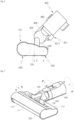
- FIG. 2 is a perspective view to describe a cleaner nozzle according to one embodiment of the present disclosure.
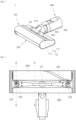
- FIG. 3 is a bottom view of FIG. 2 .
- FIG. 4 is a cross-sectional view to describe the location of a connection pipe coupling portion shown in FIG. 3 .
- FIG. 5 is a cross-sectional view to describe a caster accommodating portion shown in FIG. 3 .
- a cleaner nozzle 1 according to the present disclosure will be described as follows.
- the cleaner nozzle according to this embodiment may be connected to a hand-held cleaner or canister cleaner to be used.
- floor surface may be understood to mean not only the floor surface of a living room or bed room but also a cleaning target surface such as a carpet and etc.
- the cleaner nozzle 1 may be detachably connected to a cleaner body 2 or an extension pipe 3. As the cleaner nozzle 1 is connected to the cleaner body 2 or extension pipe 3, a user can use the cleaner nozzle 1 in cleaning the floor surface. At this time, the cleaner body 2 connected to the cleaner nozzle 1 may be configured to separate dust from air in the manner of multi-cyclone.
- the cleaner body 2 to which the cleaner nozzle 1 is connected may include a suction motor (not shown) so that suction force generated by the suction motor (not shown) may be applied to the cleaner nozzle 1.
- the upper surface 110 may be formed so that one side where the first agitator 200 is mounted can be farther from the ground than the other side where the second agitator 300 is mounted.
- the caster accommodating hole 122 may be disposed between the first agitator 200 and the second agitator 300.
- a pair of caster accommodating holes 122 may be spaced apart at a predetermined distance from left and right ends of the suction port 121. That is, the pair of caster accommodating holes 122 may be arranged on the left and right sides of the lower surface 120, respectively, with respect to the suction port 121 as the center.
- the caster accommodating portion 123 may be rotatable with respect to the axis perpendicular to the floor surface. With this configuration, there may be no restriction on the direction in which the caster 124 can roll-move.
- a plurality of casters 124 may be provided on the lower surface 120.
- a pair of casters 124 may be spaced apart from each other on the lower surface 120 in the left-right direction.
- the suction port 121 may be provided between the pair of shafts.
- At least a portion of the caster 124 may be coupled to the caster accommodating portion 123 to be disposed inside the nozzle housing 100. At least a portion of the caster 124 may be exposed to the outside of the nozzle housing 100 through the caster accommodating hole 122.
- the caster 124 may be in contact with the floor. Accordingly, when the cleaner nozzle 1 is moved by the user's manipulation, friction between the nozzle housing 100 and the floor surface may be reduced and the mobility of the cleaner nozzle 100 can be improved.
- the foreign substance blocking portion 125 may be disposed on the lower surface 120 and surround at least a portion of the caster accommodating hole 122.
- the foreign substance blocking portion 125 may be formed in a horseshoe shape protruding toward the suction port 121. With this configuration, it is possible to prevent dust moved by the rotation of the first and second agitators 200 and 300 from flowing into the caster accommodating hole 122.
- connection pipe coupling portion 130 may protrude from the upper surface 110. Specifically, based on the state where the first agitator 200 and the second agitator 300 are in contact with the floor (or ground) (i.e., the state where the cleaner nozzle 1 is placed on the floor (or ground)), the connection pipe coupling portion 130 may protrude from the upper surface 110 along a direction perpendicular to the floor.
- connection pipe coupling portion 130 may protrude from the inclined surface 113 along a direction perpendicular to the floor (or a direction perpendicular to the lower surface 120).
- connection pipe coupling portion 130 may be formed in a pair in a symmetrical shape on the upper surface 110.
- the connection pipe 400 may be rotatably coupled between the pair of connection pipe coupling portions 130.
- the pair of connection coupling portions 130 may be hingedly coupled to the connection pipe 400. That is, each of the connection pipe coupling portions 130 may have a hinge shaft coupled to the connection pipe 400, and the connection pipe 400 can pivot with respect to the hinge shaft.
- connection pipe coupling portion 130 may be disposed farther from the ground than the upper surface of the nozzle housing 100. That is, in the state where the cleaner nozzle 1 is placed on the floor surface, the connection pipe coupling portion 130 may be disposed farther from the ground than an upper end of the upper surface.
- connection pipe 400 Since the upper surface 110 is inclined downward toward the second agitator 300, the connection pipe 400 may be placed close to the floor surface (approximately parallel to the floor surface) when the connection pipe 400 rotates toward the second agitator 300. Accordingly, the overall height of the cleaner nozzle 1 may be lowered, thereby causing an advantage of allowing low areas in accessible spaces such as beds and sofas to be cleaned.
- a virtual connection pipe connecting plane P may be formed to pass through the hinge axis hinedly connecting the connection pipe 400 and the nozzle housing 100 in a direction perpendicular to the ground.
- connection pipe fixing portion 140 may be formed in the rear side of the nozzle housing 100 and detachably coupled to the connection pipe 400. Specifically, the connection pipe fixing portion 140 may protrude from a rear end of the upper surface 110 and may be secured to a locking part 432 provided in the connection pipe 400.
- connection fixing portion 140 may protrude in a hook shape to be insertedly secured to the locking part 432.
- connection fixing portion 140 may couple the nozzle housing 100 and the connection pipe 400 to each other. Accordingly, the connection pipe coupling portion 130 and the connection pipe 400 secured to the connection pipe fixing portion 140 may be restricted from rotating (or pivoting) in the left-right direction.
- connection pipe fixing portion 140 and the locking part 432 are secured, the fixing between a second steering portion 430 and a third steering portion 440, which will be described later, may be released.
- the fixing and releasing of the second steering portion 430 and the third steering portion 440 enabled by the locking part 4332 will be described later.
- the first agitator 200 may be mounted in the nozzle housing 100 and configured to separate foreign substances from a cleaning target.
- the first agitator 200 may be mounted in the front side of the cleaner nozzle 1.
- the first agitator 200 may be rotatably coupled to the nozzle housing 100.
- the first agitator 200 may be formed in a cylindrical shape, and arranged along the left-right direction of the nozzle housing 100. That is, the longitudinal direction (or axial direction) of the first agitator 200 may be arranged to intersect the forward-rearward direction of the cleaner nozzle 1.
- a brush or predetermined member configured increase friction force may be provided on the outer circumferential surface of the first agitator 200.
- the first agitator 200 may include at least one gear to receive rotation force from the agitator motor (not shown).
- the first agitator 200 may guide external dust and air to the suction port 121 by rotation.
- the first agitator 200 may be rotated in a direction in which the outer circumferential surface facing the floor moves toward the suction port 121. That is, when looking at the cleaner nozzle 1 from the left side of the cleaner nozzle 1, the first agitator 200 may be rotated counterclockwise. With this configuration, external dust and air may be guided toward the suction port 121 by friction with the first agitator 200.
- the first agitator 200 may be replaceably connected to the nozzle housing 100. Accordingly, the first agitator 200 may be replaced to perform cleaning depending on the cleaning environment.
- the second agitator 300 may be mounted in the nozzle housing and configured to separate foreign substances from a cleaning target.
- the second agitator 300 may be mounted in the rear side of the cleaner nozzle 1.
- the second agitator 300 may be rotatably coupled to the nozzle housing 100.
- the second agitator 300 be formed in a cylindrical shape, and arranged along the left-right direction of the nozzle housing 100. That is, the longitudinal direction (or axial direction) of the second agitator 300 may be arranged to intersect the forward-rearward direction of the cleaner nozzle 1.
- a brush or predetermined member configured increase friction force may be provided on the outer circumferential surface of the second agitator 300.
- the second agitator 300 may include at least one gear to receive rotation force from the agitator motor (not shown) to receive rotation force from the agitator motor (not shown). At this time, the first agitator 200 and the second agitator 300 may receive driving force from one agitator motor. As one example, the first agitator 200 and the second agitator 300 may be connected to each other by a belt, to receive driving force from the agitator motor. As another example, the first agitator 200 and the second agitator 300 may be connected to each other by at least one gear to receive driving force from the agitator motor.
- the second agitator 300 may guide external dust and air to the suction port 121 by rotation. At this time, the second agitator 300 may be rotated in the opposite direction to the first agitator 200.
- the second agitator 300 may be rotated in a direction in which its outer circumferential surface facing the floor moves toward the suction port 121. That is, when looking at the cleaner nozzle 1 from the left side of the cleaner nozzle 1, the second agitator 300 may be rotated clockwise. With this configuration, external dust and air may be guided toward the suction port 121 by friction with the first agitator 200
- dust near the suction port 121 may be collected toward the suction port 121 by the first agitator 200 and the second agitator 300, and may be sucked by the suction force of the cleaner body 2 to be removed from the floor surface.
- the second agitator 300 may be replaceably connected to the nozzle housing 100. Accordingly, the first agitator 200 may be replaced to perform cleaning depending on the cleaning environment.
- the first agitator 200 and the second agitator 300 may be replaced. Accordingly, it is possible to create various agitator combinations based on the condition of the floor surface or the cleaning environment, thereby maximizing cleaning efficiency.
- the diameter of the first agitator 200 and the diameter of the second agitator 300 may be different. Specifically, the diameter of the first agitator 200 may be larger than that of the second agitator 300.
- the torque of the second agitator 300 having the smaller diameter may be greater than the torque of the first agitator 200. That is, the rotation force required to rotate the second agitator 300 may be less than the rotation force of the first agitator 200.
- the motor output required to rotate the two agitators may be lower.
- the present disclosure it is possible to rotate the two agitators with the single agitator motor (not shown) while reducing the driving force required for the motor. Accordingly, the power consumed by the cleaner nozzle may be reduced and the load applied to the motor may be lowered.
- an inclination may be formed on the upper surface 110 of the nozzle housing 100 covering the upper portions of the first and second agitators 200 and 300. That is, when the first agitator 200 and the second agitator 300 are placed on the floor (or ground), the height of the top of the first agitator 200 may be greater than the height of the top of the second agitator 300, and a height difference may occur in the nozzle housing 100 covering them, thereby forming an inclination connecting them.
- a first agitator cover portion 111 covering the vertical top of the first agitator 200
- a second agitator cover portion 122 covering the vertical top of the second agitator 300
- an inclined surface 113 connecting the first agitator cover portion 111 and the second agitator cover portion 112 to each other.
- connection pipe 400 when the connection pipe 400 is rotated toward the second agitator 300, the position where the connection pipe 400 comes into contact with the nozzle housing 100 may be lowered. Accordingly, the connection pipe 400 may be laid close to the ground and the overall height of the cleaner nozzle 1 may be lowered.
- FIG. 6 is a view to describe a position relationship among a virtual caster passage plane, a virtual agitator passage plane, and a virtual connection pipe connecting plane in a cleaner nozzle according to one embodiment.
- a virtual agitator passage plane A may be formed that passes the rotation axis (or rotation center) of the second agitator 300 along a direction perpendicular to the floor (or ground).
- connection pipe connecting plane P may be arranged between the caster passage plane C and agitator passage plane A.
- connection pipe connecting plane P may be a virtual surface extending along a direction perpendicular to the ground at the point where the connection pipe coupling portion 130 and the connection pipe 400 are coupled to each other.
- the connection pipe connecting plane P may be a virtual surface extending along a direction perpendicular to the ground through the first steering axis X.
- the user manipulates the cleaner body 2
- he or she can pull or push the cleaner body so that the extension pipe 3 and the connection pipe 400 can press or lift the nozzle housing 100.
- the manipulating force applied by the user's pressing may be transmitted to the nozzle housing 100 through the extension pipe 3 and the connection pipe 400, and the nozzle housing 100 may be moved on the floor (or ground) by the user's manipulation force.
- connection pipe connecting plane P may mean the position and direction in which the user's manipulating force is applied.
- the caster passage plane C may be a virtual surface formed along the direction perpendicular to the ground after passing through the rotation center of the pair of casters 124. Such the caster passage plane C may be a virtual surface formed along the direction perpendicular to the ground after passing through the point where the pair of casters 124 comes into contact with the floor (or ground).
- the caster passage plane C may mean the location and direction in which the cleaner nozzle 1 presses the floor due to the load of the cleaner nozzle 1 and the user's manipulating force.
- the agitator passage plane A may mean the position and direction in which the cleaner nozzle 1 presses the floor surface due to the load of the cleaner nozzle 1 and the user's manipulating force.
- connection pipe connecting plane P is arranged between the caster passage plane C and the agitator passage plane A, the user's pressing force (or manipulating force) may be applied to the caster 124 and the second agitator 300.
- the second agitator 300 may receive less frictional resistance with respect to the ground, compared to the first agitator 200.
- the first agitator 200 and the second agitator 300 may receive the same torque from one agitator motor. At this time, when the diameter of the first agitator 200 is greater than that of the second agitator 300, the torque due to friction between the first agitator 200 and the ground may be greater than the torque due to friction between the second agitator 300 and the ground.
- the distance r1 between the rotation center of the first agitator 200 and the ground may be greater than the distance between the rotation center r2 of the second agitator 300 and the ground (r1>r2), and then the torque (r1 ⁇ F1) due to friction between the first agitator (200) and the ground is greater than the torque (r2 ⁇ F2) due to friction between the second agitator (300) and the ground.
- the second agitator 300 may be rotated even under the condition that rotation will stop.
- the diameter of the second agitator 300 may be less than the diameter of the first agitator 200 and the user's manipulating force may press the second agitator, so the second agitator 300 can be rotated even when the user cleans the floor surface with high friction such as mats or carpets. Accordingly, the cleaner nozzle 1 of the present disclosure may be easily moved forward or rearward even on the floor surface such as a mat or carpet, and has an effect of preventing the agitator motor from being overloaded.
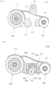
- FIG. 7 is a view to describe the steering direction of the connection pipe in a cleaner nozzle according to one embodiment.
- FIG. 8 is a bottom view to describe a connection pipe in a cleaner nozzle according to one embodiment.
- FIG. 9 is a partially enlarged view to describe a locking part and a connection pipe coupling portion in a cleaner nozzle according to one embodiment.
- FIG. 10 is a side view to describe the state where a locking part is coupled to a connection pipe coupling portion in a cleaner nozzle according to one embodiment.
- connection pipe 400 according to one embodiment will be described as follows.
- connection pipe 400 may have a path connected to the suction port 121, and may connect the nozzle housing 100 and the extension pipe 3 or the nozzle housing and the cleaner body 2.
- the connection pipe 400 may include a pipe 410, a first steering portion 420, a second steering portion 430, and a third steering portion 440.
- the pipe 410 may have a path formed therein and connected to the suction port 121.
- the pipe 410 may be coupled to the nozzle housing 100 to communicate with the path inside the nozzle housing 100.
- the pipe 410 may be formed of a deformable material. Specifically, the pipe 410 may be made of a bendable material. Accordingly, the pipe 410 may be bent and deformed based on the rotation of each of the first steering portion 420, the second steering portion 430, and the third steering portion provided in the connection pipe 400.
- the first steering portion 420 may be configured to accommodate at least a portion of the pipe 410 and hingedly coupled to the nozzle housing 100.
- the first steering portion 420 may be formed hollow so that the pipe 410 may penetrate the inside thereof, and may have one side hingedly coupled to the connection pipe coupling portion 130 and the other side hingedly coupled to the second steering portion 430.
- the axis around which the first steering portion 420 rotates with respect to the connection pipe coupling portion 130 may be arranged along a direction parallel to the floor surface (or ground).
- the cleaner body 2 and the connection pipe 400 may be rotated around the high axis.
- first steering axis X the direction of the hinge axis to which the first steering portion 420 and the connection pipe coupling portion 130 are connected
- second steering axis Y the direction of the hinge axis
- the cleaner body 2 and the connection pipe 400 may be rotated with respect to the second steering axis as a rotation center.
- connection pipe 400 may have an advantage of being bent at various angles by combining the rotation direction of the first steering portion 420 and the rotation direction of the second steering portion 430.
- the second steering portion 430 may be hingedly coupled to the first steering portion and relative-rotatably coupled to the third steering portion 430.
- the second steering portion 430 may be formed hollow so that the pipe 410 may penetrate the inside thereof, and may have one side hingedly coupled to the first steering portion 420 and the other side hingedly coupled to the third steering portion 440.
- the second steering portion 430 may have a locking part 431.
- the locking part 431 may be fixed to the second steering portion 430, and may be inserted into the third steering portion 440 while moving straight.
- the locking part 431 may include a plate-shaped stopper 431a inserted into the third steering portion 440 by the linear movement.
- the stopper 431a may be disposed at a position where it can be coupled to the connection pipe coupling portion 140.
- the stopper 41a may be released from the third steering portion 430 based on the position of the connection pipe 400.
- the stopper 431a When the connection pipe 400 is not rotated to a specific position, the stopper 431a may be positioned in a protruding form toward the third steering portion 430.
- the stopper 431a When the stopper 431a is coupled to the connection pipe fixing portion 140 along with the rotation of the connection pipe 400, the stopper 431a may be pulled toward the nozzle housing 100 and the coupling with the third steering portion 430 may be released. Meanwhile, the stopper 431a may be connected to a spring (not shown), and may return toward the third steering portion 320 when the coupling between the connection pipe fixing portion 140 and the stopper 431a is released.
- the third steering portion 440 may be rotatably coupled to the second steering 430.
- the third steering portion 440 may be formed in a shape similar to a plate, and one inner circumferential surface of the third steering portion 440 may accommodate the other end of the second steering portion 430. At this time, a hook may be formed at the other end of the second steering portion 430 to prevent the separation of the second steering portion 430 and the third steering portion 440.
- the third steering portion 440 may be rotated around the other end of the second steering portion 430 as a rotation axis.
- the rotation axis (hereinafter, referred to as the third steering axis Z) may be perpendicular to the direction of the first steering axis X and the direction of the second steering axis Y.
- the third steering portion 440 may be rotated. Due to that, the user can lay down the cleaner body 2 and clean the floor surface when the user lying and facing down cleans a narrow space where the cleaner nozzle can enter such as the bottom of a bed or furniture.
- connection pipe 400 of the present disclosure may have an advantage of being able to rotate through three axis of rotation and be bent at various angles, thereby facilitating user manipulation.
- the other side of the third steering portion 40 may be detachably coupled to the extension pipe 3 or the cleaner body 2.
- a path through which air can flow may be formed inside the third steering portion 440.
- the third steering portion 440 may be accommodated in the third steering portion 440.
- a space connected to the pipe 410 may be formed inside the third steering portion 440.
- a stopper accommodating portion may be formed in the third steering portion 440 to insert the stopper 431a therein.
- the stopper receiving portion may be formed in a shape of a square groove that can receive a plate-shaped stopper 431a.
- the third steering portion 440 may not be rotated and the entire cleaner nozzle 1 may be rotated even if the user turns the cleaner body 2.
Landscapes
- Engineering & Computer Science (AREA)
- Mechanical Engineering (AREA)
- Nozzles For Electric Vacuum Cleaners (AREA)
Abstract
Description
- Embodiments of the present disclosure relate to a cleaner nozzle, more particularly, a cleaner nozzle configured to suck dust from the floor by rotating two agitators.
- A cleaner is an electric appliance configured to suck dust and air by using suction force generated in a suction motor mounted in a cleaner body and to collect dust by separating dust from the sucked air.
- A suction nozzle refers to a part that directly sucks dust and air by coming into contact with the floor. The suction force generated in the suction motor mounted inside the cleaner body may be transmitted to the suction motor so that dust and air can be sucked into the suction nozzle by the suction force.
- An agitator may be mounted in the suction nozzle. The agitator may be configured to rotate and scrape away dust from the floor or carpet, thereby improving cleaning performance.
- Meanwhile, Korean Patent Publication No.
KR2022-0073810A - The cleaner head may include a suction chamber disposed between the front agitator and the rear agitator, and the front agitator and the rear agitator may be configured to rotate in the opposite directions so as to induce dust into the suction chamber.
- However, the above-mentioned cleaner head has the front agitator and the rear agitator that have the same size. Due to that, the cleaner body and a pipe cannot lie on the floor. Accordingly, there is a limitation that the space underneath low furniture, such as sofas or beds, where the cleaner head can fit, cannot be deep cleaned.
- In addition, since the above-mentioned cleaner head must rotate the two agitators with the same diameter, power is distributed evenly across the two agitators, thereby requiring relatively high motor output, and has the limitation of consuming a lot of power.
- In addition, during the cleaning process, if the cleaner head is pressurized by the weight of the cleaner body or the user's operating force, the two agitators with the same output and rotating in opposite directions may come into contact with the floor, causing friction to increase and stopping the rotation of the agitators. In this case, there is a disadvantage that a large load is generated on the motor, causing damage to the motor.
- Accordingly, one object of the present disclosure is to solve the above-noted disadvantages of the conventional cleaner nozzle (or cleaner nozzle), and to provide a cleaner nozzle that may lay down a cleaner body and a pipe connecting the cleaner body to the cleaner nozzle close to the ground.
- Furthermore, one object of the present disclosure is to provide a cleaner nozzle that may lower the required motor output even while rotating two agitators.
- Still further, one object of the present disclosure is to provide a cleaner that may prevent a large load from being generated in a motor by friction between the agitators and the ground even when the cleaner is pressed downward during a cleaning process.
- To solve the objects of the present disclosure, a cleaner nozzle may include a nozzle housing; a first agitator rotatably coupled to the nozzle housing; a second agitator rotatably coupled to the nozzle housing; a suction port formed between the first agitator and the second agitator, and configured to suck air containing dust; and a connection pipe in which a path in communication with the suction port is formed.
- At this time, the diameter of the first agitator may be different from the diameter of the second agitator, and based on a state where the first agitator and the second agitator are in contact with the ground, an upper surface of the nozzle housing may be inclined a predetermined angle with respect to the ground.
- At this time, the diameter of the first agitator disposed in the front side may be greater than the diameter of the second agitator disposed in the rear side. Accordingly, the cleaner body and the pipe connecting the cleaner body with the cleaner nozzle may be laid down backward.
- Meanwhile, the suction port may be formed between the first agitator and the second agitator. At this time, the cleaner nozzle may further include a caster disposed between the first agitator and the second agitator, spaced a predetermined distance apart from both longitudinal ends of the suction port. That is, the caster may be arranged between the first agitator and the second agitator.
- The cleaner of the present disclosure may further include a caster accommodating portion rotatably coupled to the caster. The caster accommodating portion may be relatively rotatable with respect to a lower surface of the nozzle housing. Accordingly, as the caster accommodating portion is rotated, the cleaner nozzle may be moved not only in a forward and rearward direction but also in various directions.
- Meanwhile, the cleaner of the present disclosure may further include a virtual caster passage plane that passes through rotation center of a pair of casters along a vertical direction; a virtual agitator passage plane that passes through a rotation axis of the second agitator along the vertical direction; and a virtual connection pipe connecting plane that passes through a hinge axis hingedly coupling the connection pipe and the nozzle housing to each other along the vertical direction. The connection pipe connecting plane may be disposed between the caster passage plane and the agitator passage plane.
- The cleaner of the present disclosure may include a connection pipe coupling portion protruding in a direction perpendicular to the ground from an upper surface of the nozzle housing, based on a state where the first agitator and the second agitator are in contact with the ground.
- Meanwhile, the connection pipe may include a pipe in which a path in communication with the suction port is formed; a first steering portion configured to accommodate at least a portion of the pipe and hingedly coupled to the nozzle housing; a second steering portion hingedly coupled to the first steering portion; and a third steering portion rotatably coupled to the second steering portion.
- At this time, the second steering portion may include a locking part coupled to the third steering portion and configured to restrict the rotation of the third steering portion
- The cleaner nozzle of the present disclosure may further include a connection pipe fixing portion formed in a rear side of the nozzle housing and secured to the locking part, and configured to release the coupling between the locking part and the third steering portion.
- Accordingly, when the locking part is secured to the connection pipe fixing portion, at least a portion of the connection pipe may be arranged closer to the ground than an upper end of the first agitator, based on the state where the first agitator and the second agitator are in contact with the ground.
- As described above, in the cleaner nozzle of the present disclosure, the diameters of the two agitators are different from each other so that the inclined surface can be formed on the upper surface of the nozzle housing. Due to that, the pipe may be laid down toward the agitator with the smaller diameter, the overall height of the cleaner nozzle may be lowered, and the pipe can be kept close to the ground. Accordingly, the cleaner nozzle may have an effect of cleaning low-heighted furniture in the lower space by the user pushing it deep into the furniture.
- Furthermore, the torque applied to the agitator with the smaller diameter may be reduced by making the diameters of the two agitators different, thereby lowering the output required for the motor. Accordingly, the cleaner nozzle of the present disclosure may have an effect of reducing the amount of the consumed power.
- When the cleaner nozzle is pressed downward, the caster and the second agitator may be pressed against the ground strongly, and the friction between the first agitator and the ground may be reduced. Accordingly, the cleaner of the present disclosure may have an effect of preventing a large load from being applied to the motor due to the friction between the first agitator and the ground.
-
-
FIG. 1 is a perspective view of a cleaner according to one embodiment of the present disclosure; -
FIG. 2 is a perspective view to describe a cleaner nozzle of one embodiment of the present disclosure; -
FIG. 3 is a bottom view ofFIG. 2 ; -
FIG. 4 is a cross-sectional view to describe the location of a connection pipe coupling portion shown inFIG. 3 ; -
FIG. 5 is a cross-sectional view to describe a caster accommodating portion shown inFIG. 3 ; -
FIG. 6 is a view to describe a position relationship among a virtual caster passage plane, a virtual agitator passage plane, and a virtual connection pipe connecting plane in a cleaner nozzle of one embodiment; -
FIG. 7 is a view to describe the steering direction of the connection pipe in a cleaner nozzle according to one embodiment; -
FIG. 8 is a bottom view to describe a connection pipe in a cleaner nozzle according to one embodiment; -
FIG. 9 is a partially enlarged view to describe a locking part and a connection pipe coupling portion in a cleaner nozzle according to one embodiment; -
FIG. 10 is a side view to describe the state where a locking part is coupled to a connection pipe coupling portion in a cleaner nozzle according to one embodiment. - Description will now be given in detail according to exemplary embodiments disclosed herein, with reference to the accompanying drawings.
- The present disclosure may be variously modified and may have various embodiments, and particular embodiments illustrated in the drawings will be specifically described below. The description of the embodiments is not intended to limit the present disclosure to the particular embodiments, but it should be interpreted that the present disclosure is to cover all modifications, equivalents and alternatives falling within the spirit and technical scope of the present disclosure.
-
FIG. 1 is a perspective view of a cleaner according to one embodiment of the present disclosure.FIG. 2 is a perspective view to describe a cleaner nozzle according to one embodiment of the present disclosure.FIG. 3 is a bottom view ofFIG. 2 .FIG. 4 is a cross-sectional view to describe the location of a connection pipe coupling portion shown inFIG. 3 .FIG. 5 is a cross-sectional view to describe a caster accommodating portion shown inFIG. 3 . - Referring to
FIG. 1 to 5 , acleaner nozzle 1 according to the present disclosure will be described as follows. - The cleaner nozzle according to this embodiment may be connected to a hand-held cleaner or canister cleaner to be used.
- In this disclosure, "floor surface" may be understood to mean not only the floor surface of a living room or bed room but also a cleaning target surface such as a carpet and etc.
- Specifically, the
cleaner nozzle 1 may be detachably connected to acleaner body 2 or anextension pipe 3. As thecleaner nozzle 1 is connected to thecleaner body 2 orextension pipe 3, a user can use thecleaner nozzle 1 in cleaning the floor surface. At this time, thecleaner body 2 connected to thecleaner nozzle 1 may be configured to separate dust from air in the manner of multi-cyclone. - The
cleaner nozzle 1 may be operated by electric power received from thecleaner body 2. Specifically, thecleaner nozzle 1 may receive power from a battery (not shown) provided in thecleaner body 2 to operate. - The
cleaner body 2 to which thecleaner nozzle 1 is connected may include a suction motor (not shown) so that suction force generated by the suction motor (not shown) may be applied to thecleaner nozzle 1. - Accordingly, the
cleaner nozzle 1 may function to suck air and foreign substances from the floor and guide them to thecleaner body 2. - The
cleaner nozzle 1 according to this embodiment may include anozzle housing 100, afirst agitator 200, and aconnection pipe 400. - Here, the directions used in the present disclosure will be described as follows.
- In the present disclosure, the directions of the
cleaner nozzle 1 may be defined based on asuction port 121. Specifically, the direction in which thefirst agitator 200 is arranged based on thesuction port 121 may be referred to as the front of the cleaner nozzle 1 (or forward), and the direction in which thesecond agitator 300 is arranged based on thesuction port 121 may be referred to as the rear of the cleaner nozzle 1 (or rearward). In addition, based on the stat where thecleaner nozzle 1 is placed on the floor (or ground) (i.e., the state where thefirst agitator 200 and thesecond agitator 300 are in contact with the floor), the direction getting farther from the floor may be referred to as the top side (upward), and the direction getting closer to the floor may be referred to as the lower side (downward). - The
nozzle housing 100 may accommodate thefirst agitator 200 and thesecond agitator 300 and define the exterior of thecleaner nozzle 1. In addition, theconnection pipe 400 may be coupled to thenozzle housing 100. - The
nozzle housing 100 may include anupper surface 110 to which theconnection pipe 400 is coupled. A connectionpipe coupling portion 130 may protrude from theupper surface 110, and the connectionpipe coupling portion 130 may be hingedly coupled to theconnection pipe 400. - Based on the state where the
first agitator 200 and thesecond agitator 300 are in contact with the floor surface (or ground), theupper surface 110 of thenozzle housing 100 may be inclined at a predetermined angle with respect to the ground. - Specifically, based on the state where the
first agitator 200 and thesecond agitator 300 are in contact with the floor (or ground), theupper surface 110 may be formed so that one side where thefirst agitator 200 is mounted can be farther from the ground than the other side where thesecond agitator 300 is mounted. - Accordingly, this embodiment may have an advantage in that the rear height may be reduced among the total height of the
nozzle housing 100. If the rear height is lowered, theconnection pipe 400 hingedly connected to thenozzle housing 100 may be rotated at a larger angle toward the rear side of thecleaner nozzle 1. In this instance, the height from the ground to the uppermost end of theconnection pipe 400 may be lowered. There may be an advantage in that the lower the height from the ground to the top end of theconnection pipe 400 as described above, the more the cleaner nozzle may be inserted into narrow spaces under furniture or chairs, and the wider the area that can be cleaned. - The
nozzle housing 100 may include alower surface 120 on which thefirst agitator 200 and thesecond agitator 300 are mounted. - At this time, the
lower surface 120 may be arranged to face the floor surface while thenozzle housing 100 is placed on the floor surface (or ground). - The
suction port 121 may be formed in thenozzle housing 100. Specifically, thesuction port 121 may be formed on thelower surface 120 of thenozzle housing 100. Thesuction port 121 may mean a space through which air containing dust may be introduced. With this configuration, when the suction motor (not shown) of thecleaner body 2 operates, dust and air existing near the floor may be introduced into a path of thecleaner nozzle 1 through thesuction port 121. - Inside the
nozzle housing 100, a printed circuit board (not shown) configured to control an agitator motor (not shown) may be disposed. - In addition, a path may be formed in the
nozzle housing 100 to guide the air introduced through thesuction port 121 to thecleaner body 2. - The path may be arranged inside the
nozzle housing 100, and a lower end of the path may be in communication with thesuction port 121 and an upper end thereof may be connected to theconnection pipe 400. - At this time, the path connecting the
suction port 121 and theconnection pipe 400 may be formed approximately along a vertical direction. With this configuration, there is an advantage in that the path for sucking the air containing dust may be minimized and the loss of flow rate may be minimized. - A caster
accommodating hole 122 may be formed in thenozzle housing 100. Specifically, the casteraccommodating hole 122 may be formed on thelower surface 120 of thenozzle housing 100. The casteraccommodating hole 122 may mean a space that exposes at least a portion of acaster 124 to the outside. - The caster
accommodating hole 122 may be disposed between thefirst agitator 200 and thesecond agitator 300. In addition, a pair of casteraccommodating holes 122 may be spaced apart at a predetermined distance from left and right ends of thesuction port 121. That is, the pair of casteraccommodating holes 122 may be arranged on the left and right sides of thelower surface 120, respectively, with respect to thesuction port 121 as the center. - With this configuration, the caster
accommodating hole 122 may allow thecaster 124 disposed between thefirst agitator 200 and thesecond agitator 300. Accordingly, when an external shock is applied during the cleaning operation, thecaster 124 can support thenozzle housing 100 and it is possible to prevent the load applied to the agitator motor (not shown) from increasing due to excessive external shock applied to thefirst agitator 200 and/or thesecond agitator 300. - In addition, a predetermined distance may be provided between the
suction port 121 and the casteraccommodating hole 122, thereby preventing dust flowing toward thesuction port 121 from flowing into the casteraccommodating hole 122. - The caster
accommodating hole 122 may be formed so that thecaster 124 may rotate relative thereto. For example, the casteraccommodating hole 122 may be formed in a circular or overall hole shape. Accordingly, even if the casteraccommodating portion 123 and thecaster 124 rotate around a rotation axis perpendicular to the ground, it is possible to prevent inference with thelower surface 120. - The caster
accommodating portion 123 may be rotatably coupled to thecaster 124, and configured to be rotatably relative to thelower surface 120 of thenozzle housing 100. - The caster
accommodating portion 123 may be provided in the inner space of thenozzle housing 100. That is, the caster accommodating portion123 may be arranged in a space formed between thelower surface 120 and theupper surface 110 of thenozzle housing 100. At this time, ashaft 123a provided in the casteraccommodating portion 123 may be rotatably coupled to thenozzle housing 100. Theshaft 123a of the casteraccommodating portion 123 may be formed along a direction perpendicular to thelower surface 120. Accordingly, with respect to the state where thecleaner nozzle 1 is placed on the floor, the casteraccommodating portion 123 may be rotatable on the axis perpendicular to the floor surface. - The caster
accommodating portion 123 may be formed in a shape that can accommodate at least a portion of thecaster 124. For example, the casteraccommodating portion 123 may have acover surface 123b formed along a direction perpendicular to theshaft 123a (i.e., a direction parallel to the lower surface 120). In addition, the casteraccommodating portion 123 may have alateral wall surface 123c extending from thecover surface 123b downward in the vertical direction. Acaster shaft 123d that is a rotation axis of thecaster 124 may be coupled to thelateral wall surface 123c. At this time, thecaster shaft 123d may be formed along a direction parallel to the extension direction of the lower surface 120 (a direction parallel to the floor surface). - Accordingly, the caster
accommodating portion 123 may be rotatable with respect to the axis perpendicular to the floor surface. With this configuration, there may be no restriction on the direction in which thecaster 124 can roll-move. - According to the present disclosure, even when the user moves the
cleaner nozzle 1 in the forward-rearward direction, left-right direction, or diagonal direction, the casteraccommodating portion 123 may rotate to change the direction in which thecaster 124 can roll. - As a result, even when the user pushes or pull the
cleaner nozzle 1 in various directions, thecaster 124 can change its directions to roll along the floor, thereby causing an effect of improving the user's manipulation convenience. - The
caster 124 may be rotatably coupled to the casteraccommodating portion 123 to be disposed on thelower surface 120 and configured to roll along the floor surface (or ground). - A plurality of
casters 124 may be provided on thelower surface 120. For example, a pair ofcasters 124 may be spaced apart from each other on thelower surface 120 in the left-right direction. At this time, thesuction port 121 may be provided between the pair of shafts. - Each of the
casters 124 may be rotatably coupled to the casteraccommodating portion 123 by thecaster shaft 123d. - At least a portion of the
caster 124 may be coupled to the casteraccommodating portion 123 to be disposed inside thenozzle housing 100. At least a portion of thecaster 124 may be exposed to the outside of thenozzle housing 100 through the casteraccommodating hole 122. - With this configuration, when the
cleaner nozzle 1 is placed on the floor, thecaster 124 may be in contact with the floor. Accordingly, when thecleaner nozzle 1 is moved by the user's manipulation, friction between thenozzle housing 100 and the floor surface may be reduced and the mobility of thecleaner nozzle 100 can be improved. - Meanwhile, a virtual caster passage surface C extending along a direction parallel to the floor surface through the rotation center of the pair of casters may be formed.
- In this embodiment, a foreign
substance blocking portion 125 may be further provided in the outside of the casteraccommodating hole 122. - The foreign
substances blocking portion 125 may be formed in a shape or material that can increase friction. As one example, the foreignsubstance blocking portion 125 may be formed in a shape with multiple fine protrusions formed thereon. As another example, the foreignsubstance blocking portion 125 may be formed of a rubber material. Accordingly, the foreignsubstance blocking portion 125 may block foreign substances from penetrate the surface thereof. - The foreign
substance blocking portion 125 may be disposed on thelower surface 120 and surround at least a portion of the casteraccommodating hole 122. For example, the foreignsubstance blocking portion 125 may be formed in a horseshoe shape protruding toward thesuction port 121. With this configuration, it is possible to prevent dust moved by the rotation of the first andsecond agitators accommodating hole 122. - Meanwhile, the connection
pipe coupling portion 130 may protrude from theupper surface 110. Specifically, based on the state where thefirst agitator 200 and thesecond agitator 300 are in contact with the floor (or ground) (i.e., the state where thecleaner nozzle 1 is placed on the floor (or ground)), the connectionpipe coupling portion 130 may protrude from theupper surface 110 along a direction perpendicular to the floor. - In particular, the connection
pipe coupling portion 130 may protrude from theinclined surface 113 along a direction perpendicular to the floor (or a direction perpendicular to the lower surface 120). - The connection
pipe coupling portion 130 may be formed in a pair in a symmetrical shape on theupper surface 110. Theconnection pipe 400 may be rotatably coupled between the pair of connectionpipe coupling portions 130. Specifically, the pair ofconnection coupling portions 130 may be hingedly coupled to theconnection pipe 400. That is, each of the connectionpipe coupling portions 130 may have a hinge shaft coupled to theconnection pipe 400, and theconnection pipe 400 can pivot with respect to the hinge shaft. - At this time, an upper end of the connection
pipe coupling portion 130 may be disposed farther from the ground than the upper surface of thenozzle housing 100. That is, in the state where thecleaner nozzle 1 is placed on the floor surface, the connectionpipe coupling portion 130 may be disposed farther from the ground than an upper end of the upper surface. - With this configuration, it is possible to secure a sufficient angle to rotate the
connection pipe 400. Since theupper surface 110 is inclined downward toward thesecond agitator 300, theconnection pipe 400 may be placed close to the floor surface (approximately parallel to the floor surface) when theconnection pipe 400 rotates toward thesecond agitator 300. Accordingly, the overall height of thecleaner nozzle 1 may be lowered, thereby causing an advantage of allowing low areas in accessible spaces such as beds and sofas to be cleaned. - Meanwhile, a virtual connection pipe connecting plane P may be formed to pass through the hinge axis hinedly connecting the
connection pipe 400 and thenozzle housing 100 in a direction perpendicular to the ground. - A connection
pipe fixing portion 140 may be formed in the rear side of thenozzle housing 100 and detachably coupled to theconnection pipe 400. Specifically, the connectionpipe fixing portion 140 may protrude from a rear end of theupper surface 110 and may be secured to a locking part 432 provided in theconnection pipe 400. - For example, the
connection fixing portion 140 may protrude in a hook shape to be insertedly secured to the locking part 432. - With this configuration, the
connection fixing portion 140 may couple thenozzle housing 100 and theconnection pipe 400 to each other. Accordingly, the connectionpipe coupling portion 130 and theconnection pipe 400 secured to the connectionpipe fixing portion 140 may be restricted from rotating (or pivoting) in the left-right direction. - At the same time when the connection
pipe fixing portion 140 and the locking part 432 are secured, the fixing between asecond steering portion 430 and athird steering portion 440, which will be described later, may be released. The fixing and releasing of thesecond steering portion 430 and thethird steering portion 440 enabled by the locking part 4332 will be described later. - The
first agitator 200 may be mounted in thenozzle housing 100 and configured to separate foreign substances from a cleaning target. Thefirst agitator 200 may be mounted in the front side of thecleaner nozzle 1. Thefirst agitator 200 may be rotatably coupled to thenozzle housing 100. - The
first agitator 200 may be formed in a cylindrical shape, and arranged along the left-right direction of thenozzle housing 100. That is, the longitudinal direction (or axial direction) of thefirst agitator 200 may be arranged to intersect the forward-rearward direction of thecleaner nozzle 1. - A brush or predetermined member configured increase friction force may be provided on the outer circumferential surface of the
first agitator 200. - The
first agitator 200 may include at least one gear to receive rotation force from the agitator motor (not shown). - The
first agitator 200 may guide external dust and air to thesuction port 121 by rotation. Thefirst agitator 200 may be rotated in a direction in which the outer circumferential surface facing the floor moves toward thesuction port 121. That is, when looking at thecleaner nozzle 1 from the left side of thecleaner nozzle 1, thefirst agitator 200 may be rotated counterclockwise. With this configuration, external dust and air may be guided toward thesuction port 121 by friction with thefirst agitator 200. - Meanwhile, the
first agitator 200 may be replaceably connected to thenozzle housing 100. Accordingly, thefirst agitator 200 may be replaced to perform cleaning depending on the cleaning environment. - The
second agitator 300 may be mounted in the nozzle housing and configured to separate foreign substances from a cleaning target. Thesecond agitator 300 may be mounted in the rear side of thecleaner nozzle 1. Thesecond agitator 300 may be rotatably coupled to thenozzle housing 100. - The
second agitator 300 be formed in a cylindrical shape, and arranged along the left-right direction of thenozzle housing 100. That is, the longitudinal direction (or axial direction) of thesecond agitator 300 may be arranged to intersect the forward-rearward direction of thecleaner nozzle 1. - A brush or predetermined member configured increase friction force may be provided on the outer circumferential surface of the
second agitator 300. - The
second agitator 300 may include at least one gear to receive rotation force from the agitator motor (not shown) to receive rotation force from the agitator motor (not shown). At this time, thefirst agitator 200 and thesecond agitator 300 may receive driving force from one agitator motor. As one example, thefirst agitator 200 and thesecond agitator 300 may be connected to each other by a belt, to receive driving force from the agitator motor. As another example, thefirst agitator 200 and thesecond agitator 300 may be connected to each other by at least one gear to receive driving force from the agitator motor. - The
second agitator 300 may guide external dust and air to thesuction port 121 by rotation. At this time, thesecond agitator 300 may be rotated in the opposite direction to thefirst agitator 200. - Specifically, the
second agitator 300 may be rotated in a direction in which its outer circumferential surface facing the floor moves toward thesuction port 121. That is, when looking at thecleaner nozzle 1 from the left side of thecleaner nozzle 1, thesecond agitator 300 may be rotated clockwise. With this configuration, external dust and air may be guided toward thesuction port 121 by friction with thefirst agitator 200 - With this configuration, dust near the
suction port 121 may be collected toward thesuction port 121 by thefirst agitator 200 and thesecond agitator 300, and may be sucked by the suction force of thecleaner body 2 to be removed from the floor surface. - Meanwhile, the
second agitator 300 may be replaceably connected to thenozzle housing 100. Accordingly, thefirst agitator 200 may be replaced to perform cleaning depending on the cleaning environment. - Furthermore, in the
cleaner nozzle 1 according to the present disclosure, thefirst agitator 200 and thesecond agitator 300 may be replaced. Accordingly, it is possible to create various agitator combinations based on the condition of the floor surface or the cleaning environment, thereby maximizing cleaning efficiency. - Meanwhile, in the
cleaner nozzle 1 according to this embodiment, the diameter of thefirst agitator 200 and the diameter of thesecond agitator 300 may be different. Specifically, the diameter of thefirst agitator 200 may be larger than that of thesecond agitator 300. - When the diameter of the
first agitator 200 is larger than that of thesecond agitator 300, the torque of thesecond agitator 300 having the smaller diameter may be greater than the torque of thefirst agitator 200. That is, the rotation force required to rotate thesecond agitator 300 may be less than the rotation force of thefirst agitator 200. - Accordingly, compared to the case of rotating two agitator having the same diameter, when the diameter of the
second agitator 300 is less than that of thefirst agitator 200 as in the present disclosure, the motor output required to rotate the two agitators may be lower. - Therefore, according to the present disclosure, it is possible to rotate the two agitators with the single agitator motor (not shown) while reducing the driving force required for the motor. Accordingly, the power consumed by the cleaner nozzle may be reduced and the load applied to the motor may be lowered.
- Since the diameter of the
first agitator 200 is greater than that of thesecond agitator 300, an inclination may be formed on theupper surface 110 of thenozzle housing 100 covering the upper portions of the first andsecond agitators first agitator 200 and thesecond agitator 300 are placed on the floor (or ground), the height of the top of thefirst agitator 200 may be greater than the height of the top of thesecond agitator 300, and a height difference may occur in thenozzle housing 100 covering them, thereby forming an inclination connecting them. Specifically, on theupper surface 110 of thenozzle housing 100 may be formed a firstagitator cover portion 111 covering the vertical top of thefirst agitator 200, a secondagitator cover portion 122 covering the vertical top of thesecond agitator 300, and aninclined surface 113 connecting the firstagitator cover portion 111 and the secondagitator cover portion 112 to each other. - With this configuration, when the
connection pipe 400 is rotated toward thesecond agitator 300, the position where theconnection pipe 400 comes into contact with thenozzle housing 100 may be lowered. Accordingly, theconnection pipe 400 may be laid close to the ground and the overall height of thecleaner nozzle 1 may be lowered. - Meanwhile,
FIG. 6 is a view to describe a position relationship among a virtual caster passage plane, a virtual agitator passage plane, and a virtual connection pipe connecting plane in a cleaner nozzle according to one embodiment. - Referring to
FIG. 6 , a virtual agitator passage plane A may be formed that passes the rotation axis (or rotation center) of thesecond agitator 300 along a direction perpendicular to the floor (or ground). - Hereinafter, the arrangement relationship and its effects of the agitator passing plane A and the connection pipe connecting plane will be described.
- In the
cleaner nozzle 1 according to one embodiment, the connection pipe connecting plane P may be arranged between the caster passage plane C and agitator passage plane A. - Here, the connection pipe connecting plane P may be a virtual surface extending along a direction perpendicular to the ground at the point where the connection
pipe coupling portion 130 and theconnection pipe 400 are coupled to each other. In other words, based on the state where thecleaner nozzle 1 is placed on the ground (or floor), the connection pipe connecting plane P may be a virtual surface extending along a direction perpendicular to the ground through the first steering axis X. - When the user manipulates the
cleaner body 2, he or she can pull or push the cleaner body so that theextension pipe 3 and theconnection pipe 400 can press or lift thenozzle housing 100. At this time, the manipulating force applied by the user's pressing may be transmitted to thenozzle housing 100 through theextension pipe 3 and theconnection pipe 400, and thenozzle housing 100 may be moved on the floor (or ground) by the user's manipulation force. - At this time, the user's manipulating force may be applied through the point where the
connection coupling portion 130 is coupled to theconnection pipe 400, and applied downward in the direction perpendicular to the ground along the connectionpipe coupling portion 130. That is, the connection pipe connecting plane P may mean the position and direction in which the user's manipulating force is applied. - Meanwhile, the caster passage plane C may be a virtual surface formed along the direction perpendicular to the ground after passing through the rotation center of the pair of
casters 124. Such the caster passage plane C may be a virtual surface formed along the direction perpendicular to the ground after passing through the point where the pair ofcasters 124 comes into contact with the floor (or ground). - Accordingly, the caster passage plane C may mean the location and direction in which the
cleaner nozzle 1 presses the floor due to the load of thecleaner nozzle 1 and the user's manipulating force. - Meanwhile, the agitator passage plane A may be a virtual surface extending along the direction perpendicular to the ground after passing through the rotation axis of the second agitator. Such the agitator passage plane A may be a virtual surface formed along the direction perpendicular to the ground after passing a line where the
second agitator 300 comes into contact with the floor. - Accordingly, the agitator passage plane A may mean the position and direction in which the
cleaner nozzle 1 presses the floor surface due to the load of thecleaner nozzle 1 and the user's manipulating force. - Therefore, since the connection pipe connecting plane P is arranged between the caster passage plane C and the agitator passage plane A, the user's pressing force (or manipulating force) may be applied to the
caster 124 and thesecond agitator 300. - With this configuration, when the
cleaner nozzle 1 may be pressed downward by the user's manipulating force, thecaster 124 and thesecond agitator 300 may be pressed toward the ground and the friction between thefirst agitator 200 and the ground may be reduced relatively. Accordingly, it is possible to prevent a large load from being applied to the agitator motor due to friction between thefirst agitator 200 and the ground. - Meanwhile, when the
caster 124 and thesecond agitator 300 are pressed toward the ground, thesecond agitator 300 may receive less frictional resistance with respect to the ground, compared to thefirst agitator 200. - Specifically, the
first agitator 200 and thesecond agitator 300 may receive the same torque from one agitator motor. At this time, when the diameter of thefirst agitator 200 is greater than that of thesecond agitator 300, the torque due to friction between thefirst agitator 200 and the ground may be greater than the torque due to friction between thesecond agitator 300 and the ground. - For example, if friction F1 between the
first agitator 200 and the ground is equal to friction F2 between thesecond agitator 300 and the ground (F1=F2), the distance r1 between the rotation center of thefirst agitator 200 and the ground may be greater than the distance between the rotation center r2 of thesecond agitator 300 and the ground (r1>r2), and then the torque (r1×F1) due to friction between the first agitator (200) and the ground is greater than the torque (r2×F2) due to friction between the second agitator (300) and the ground. - Accordingly, if the
first agitator 200 rubbed against the ground, thesecond agitator 300 may be rotated even under the condition that rotation will stop. - Therefore, in the present disclosure, the diameter of the
second agitator 300 may be less than the diameter of thefirst agitator 200 and the user's manipulating force may press the second agitator, so thesecond agitator 300 can be rotated even when the user cleans the floor surface with high friction such as mats or carpets. Accordingly, thecleaner nozzle 1 of the present disclosure may be easily moved forward or rearward even on the floor surface such as a mat or carpet, and has an effect of preventing the agitator motor from being overloaded. -
FIG. 7 is a view to describe the steering direction of the connection pipe in a cleaner nozzle according to one embodiment.FIG. 8 is a bottom view to describe a connection pipe in a cleaner nozzle according to one embodiment.FIG. 9 is a partially enlarged view to describe a locking part and a connection pipe coupling portion in a cleaner nozzle according to one embodiment.FIG. 10 is a side view to describe the state where a locking part is coupled to a connection pipe coupling portion in a cleaner nozzle according to one embodiment. - Referring to
FIGS. 7 to 10 , theconnection pipe 400 according to one embodiment will be described as follows. - The
connection pipe 400 may have a path connected to thesuction port 121, and may connect thenozzle housing 100 and theextension pipe 3 or the nozzle housing and thecleaner body 2. - The
connection pipe 400 may include apipe 410, afirst steering portion 420, asecond steering portion 430, and athird steering portion 440. - The
pipe 410 may have a path formed therein and connected to thesuction port 121. Thepipe 410 may be coupled to thenozzle housing 100 to communicate with the path inside thenozzle housing 100. - The
pipe 410 may be formed of a deformable material. Specifically, thepipe 410 may be made of a bendable material. Accordingly, thepipe 410 may be bent and deformed based on the rotation of each of thefirst steering portion 420, thesecond steering portion 430, and the third steering portion provided in theconnection pipe 400. - The
first steering portion 420 may be configured to accommodate at least a portion of thepipe 410 and hingedly coupled to thenozzle housing 100. - The
first steering portion 420 may be formed hollow so that thepipe 410 may penetrate the inside thereof, and may have one side hingedly coupled to the connectionpipe coupling portion 130 and the other side hingedly coupled to thesecond steering portion 430. - At this time, the axis around which the
first steering portion 420 rotates with respect to the connectionpipe coupling portion 130 may be arranged along a direction parallel to the floor surface (or ground). - With this configuration, when the user places the
cleaner nozzle 1 on the floor surface and lifts or lowers thecleaner body 2, thecleaner body 2 and theconnection pipe 400 may be rotated around the high axis. - In addition, the direction of the hinge axis (hereinafter, referred to as the first steering axis X) to which the
first steering portion 420 and the connectionpipe coupling portion 130 are connected may be perpendicular to the direction of the hinge axis (hereinafter, referred to as the second steering axis Y) to which thefirst steering portion 420 and thesecond steering portion 430 are connected. - With this configuration, when the user places the
cleaner nozzle 1 on the floor surface and moves thecleaner body 2 in the left-right direction, thecleaner body 2 and theconnection pipe 400 may be rotated with respect to the second steering axis as a rotation center. - The direction in which the
first steering portion 420 is pivoted with respect to thenozzle housing 100 may intersect the direction in which thesecond steering portion 430 is pivoted with respect to thefirst steering portion 420. Accordingly, in thecleaner nozzle 1 of the present disclosure, theconnection pipe 400 may have an advantage of being bent at various angles by combining the rotation direction of thefirst steering portion 420 and the rotation direction of thesecond steering portion 430. - The
second steering portion 430 may be hingedly coupled to the first steering portion and relative-rotatably coupled to thethird steering portion 430. - Specifically, the
second steering portion 430 may be formed hollow so that thepipe 410 may penetrate the inside thereof, and may have one side hingedly coupled to thefirst steering portion 420 and the other side hingedly coupled to thethird steering portion 440. - The
second steering portion 430 may have a lockingpart 431. The lockingpart 431 may be fixed to thesecond steering portion 430, and may be inserted into thethird steering portion 440 while moving straight. For example, the lockingpart 431 may include a plate-shaped stopper 431a inserted into thethird steering portion 440 by the linear movement. The stopper 431a may be disposed at a position where it can be coupled to the connectionpipe coupling portion 140. - The stopper 41a may be released from the
third steering portion 430 based on the position of theconnection pipe 400. When theconnection pipe 400 is not rotated to a specific position, the stopper 431a may be positioned in a protruding form toward thethird steering portion 430. When the stopper 431a is coupled to the connectionpipe fixing portion 140 along with the rotation of theconnection pipe 400, the stopper 431a may be pulled toward thenozzle housing 100 and the coupling with thethird steering portion 430 may be released. Meanwhile, the stopper 431a may be connected to a spring (not shown), and may return toward the third steering portion 320 when the coupling between the connectionpipe fixing portion 140 and the stopper 431a is released. - The
third steering portion 440 may be rotatably coupled to thesecond steering 430. For example, thethird steering portion 440 may be formed in a shape similar to a plate, and one inner circumferential surface of thethird steering portion 440 may accommodate the other end of thesecond steering portion 430. At this time, a hook may be formed at the other end of thesecond steering portion 430 to prevent the separation of thesecond steering portion 430 and thethird steering portion 440. - The
third steering portion 440 may be rotated around the other end of thesecond steering portion 430 as a rotation axis. At this time, the rotation axis (hereinafter, referred to as the third steering axis Z) may be perpendicular to the direction of the first steering axis X and the direction of the second steering axis Y. - With this configuration, when the user places the
cleaner nozzle 1 on the floor surface and roll thecleaner body 2, thethird steering portion 440 may be rotated. Due to that, the user can lay down thecleaner body 2 and clean the floor surface when the user lying and facing down cleans a narrow space where the cleaner nozzle can enter such as the bottom of a bed or furniture. - Therefore, the
connection pipe 400 of the present disclosure may have an advantage of being able to rotate through three axis of rotation and be bent at various angles, thereby facilitating user manipulation. - The other side of the third steering portion 40 may be detachably coupled to the
extension pipe 3 or thecleaner body 2. - A path through which air can flow may be formed inside the
third steering portion 440. As one example, thethird steering portion 440 may be accommodated in thethird steering portion 440. As another example, a space connected to thepipe 410 may be formed inside thethird steering portion 440. - A stopper accommodating portion (not shown) may be formed in the
third steering portion 440 to insert the stopper 431a therein. For example, although not shown, the stopper receiving portion (not shown) may be formed in a shape of a square groove that can receive a plate-shaped stopper 431a. - When the stopper 431a is coupled to the stopper accommodating portion (not shown), the relative rotation of the
third steering portion 440 with respect to thesecond steering portion 430 is restricted. - With this configuration, at the position where the rotation of the
third steering portion 440 is unnecessary, thethird steering portion 440 may not be rotated and the entirecleaner nozzle 1 may be rotated even if the user turns thecleaner body 2. - Although the present invention has been described with reference to the exemplified drawings, it is to be understood that the present invention is not limited to the embodiments and drawings disclosed in this specification, and those skilled in the art will appreciate that various modifications are possible without departing from the scope of the present invention.
- Further, although the operating effects according to the configuration of the present invention are not explicitly described while describing an embodiment of the present invention, it should be appreciated that predictable effects are also to be recognized by the configuration.
Claims (11)
- A cleaner nozzle comprising:a nozzle housing;a first agitator rotatably coupled to the nozzle housing;a second agitator rotatably coupled to the nozzle housing;a suction port formed between the first agitator and the second agitator, and configured to suck air containing dust; anda connection pipe in which a path in communication with the suction port is formed,wherein the diameter of the first agitator is different from the diameter of the second agitator, and based on a state where the first agitator and the second agitator are in contact with the ground, an upper surface of the nozzle housing is inclined a predetermined angle with respect to the ground.
- The cleaner nozzle of claim 1, wherein the diameter of the first agitator is greater than the diameter of the second agitator.
- The cleaner nozzle of claim 1, further comprising a caster disposed between the first agitator and the second agitator, spaced a predetermined distance apart from both longitudinal ends of the suction port.
- The cleaner of claim 3, further comprising a caster accommodating portion rotatably coupled to the caster,
wherein the caster accommodating portion is relatively rotatable with respect to a lower surface of the nozzle housing. - The cleaner of claim 3, further comprising:a virtual caster passage plane that passes through rotation center of a pair of casters along a vertical direction;a virtual agitator passage plane that passes through a rotation axis of the second agitator along the vertical direction; anda virtual connection pipe connecting plane that passes through a hinge axis hingedly coupling the connection pipe and the nozzle housing to each other along the vertical direction,wherein the connection pipe connecting plane is disposed between the caster passage plane and the agitator passage plane.
- The cleaner of claim 1, wherein the first agitator is rotated in the opposite direction to the second agitator.
- The cleaner nozzle of claim 1, further comprising a connection pipe coupling portion protruding in a direction perpendicular to the ground from an upper surface of the nozzle housing and hingedly coupled to the connection pipe, based on a state where the first agitator and the second agitator are in contact with the ground.
- The cleaner nozzle of claim 7, wherein based on the state where the first agitator and the second agitator are in contact with the ground, an upper end of the connection pipe coupling portion is arranged farther than an upper surface of the nozzle housing.
- The cleaner nozzle of claim 7, wherein the connection pipe comprises,a pipe in which a path in communication with the suction port is formed;a first steering portion configured to accommodate at least a portion of the pipe and hingedly coupled to the nozzle housing;a second steering portion hingedly coupled to the first steering portion; anda third steering portion rotatably coupled to the second steering portion, and the second steering portion comprises,a locking part coupled to the third steering portion and configured to restrict the rotation of the third steering portion.
- The cleaner nozzle of claim 9, further comprising a connection pipe fixing portion formed in a rear side of the nozzle housing and secured to the locking part, and configured to release the coupling between the locking part and the third steering portion.
- The cleaner nozzle of claim 10, wherein when the locking part is secured to the connection pipe fixing portion, at least a portion of the connection pipe is arranged closer to the ground than an upper end of the first agitator based on the state where the first agitator and the second agitator are in contact with the ground.
Applications Claiming Priority (2)
| Application Number | Priority Date | Filing Date | Title |
|---|---|---|---|
| KR1020220117117A KR102811357B1 (en) | 2022-09-16 | 2022-09-16 | Nozzle for cleaner |
| PCT/KR2023/014030 WO2024058632A1 (en) | 2022-09-16 | 2023-09-18 | Vacuum cleaner nozzle |
Publications (2)
| Publication Number | Publication Date |
|---|---|
| EP4573997A1 true EP4573997A1 (en) | 2025-06-25 |
| EP4573997A4 EP4573997A4 (en) | 2025-12-10 |
Family
ID=90275412
Family Applications (1)
| Application Number | Title | Priority Date | Filing Date |
|---|---|---|---|
| EP23865925.4A Pending EP4573997A4 (en) | 2022-09-16 | 2023-09-18 | VACUUM NOZZLE |
Country Status (4)
| Country | Link |
|---|---|
| EP (1) | EP4573997A4 (en) |
| KR (1) | KR102811357B1 (en) |
| CN (1) | CN119923216A (en) |
| WO (1) | WO2024058632A1 (en) |
Family Cites Families (12)
| Publication number | Priority date | Publication date | Assignee | Title |
|---|---|---|---|---|
| JP4838978B2 (en) | 2002-12-16 | 2011-12-14 | アイロボット コーポレイション | Autonomous floor cleaning robot |
| KR100539758B1 (en) * | 2004-01-29 | 2006-01-11 | 엘지전자 주식회사 | Quick-drying water cleaner |
| WO2007065034A1 (en) | 2005-12-02 | 2007-06-07 | Irobot Corporation | Modular robot |
| KR101393492B1 (en) * | 2007-05-31 | 2014-05-15 | 삼성전자주식회사 | Apparatus for opening and closing dust collector for use in vacuum cleaner |
| CN111281266B (en) * | 2011-04-29 | 2021-12-10 | 艾罗伯特公司 | Mobile cleaning robot and autonomous coverage robot |
| GB201313707D0 (en) * | 2013-07-31 | 2013-09-11 | Dyson Technology Ltd | Cleaner head for a vacuum cleaner |
| GB2530933B (en) | 2013-11-25 | 2017-06-07 | Hoover Ltd | Vacuum cleaner head |
| DE102014116589B4 (en) | 2014-11-13 | 2019-02-07 | Vorwerk & Co. Interholding Gmbh | Suction nozzle with a support roller |
| GB2550180B (en) * | 2016-05-11 | 2018-05-02 | Lupe Tech Limited | Cleaner head |
| KR102308483B1 (en) * | 2017-03-13 | 2021-10-06 | 삼성전자주식회사 | Cleaner head and vacuum cleaner having the same |
| JP7267867B2 (en) * | 2019-07-23 | 2023-05-02 | 東芝ライフスタイル株式会社 | Vacuum cleaner suction and vacuum cleaner |
| KR102809012B1 (en) * | 2019-10-02 | 2025-05-19 | 다이슨 테크놀러지 리미티드 | Vacuum cleaner head for vacuum cleaner |
-
2022
- 2022-09-16 KR KR1020220117117A patent/KR102811357B1/en active Active
-
2023
- 2023-09-18 WO PCT/KR2023/014030 patent/WO2024058632A1/en not_active Ceased
- 2023-09-18 EP EP23865925.4A patent/EP4573997A4/en active Pending
- 2023-09-18 CN CN202380066183.4A patent/CN119923216A/en active Pending
Also Published As
| Publication number | Publication date |
|---|---|
| WO2024058632A1 (en) | 2024-03-21 |
| EP4573997A4 (en) | 2025-12-10 |
| KR20240038377A (en) | 2024-03-25 |
| CN119923216A (en) | 2025-05-02 |
| KR102811357B1 (en) | 2025-05-22 |
Similar Documents
| Publication | Publication Date | Title |
|---|---|---|
| US11766159B2 (en) | Vacuum cleaner | |
| US11751741B2 (en) | Vacuum cleaner | |
| AU2001287872B2 (en) | A floor tool | |
| JP5589092B2 (en) | Vacuum cleaner head | |
| JP5745543B2 (en) | Vacuum cleaner head | |
| EP2027805B1 (en) | Suction brush for vacuum cleaner | |
| US11819179B2 (en) | Cleaning tool and electric cleaner | |
| US9826870B2 (en) | Robotic vacuum cleaner | |
| CN115381329A (en) | Surface cleaning device with brake assembly | |
| EP4573997A1 (en) | Vacuum cleaner nozzle | |
| JP2017164022A (en) | Vacuum cleaner and vacuum cleaner | |
| CN217524979U (en) | Scrubbing brush device and cleaning equipment | |
| KR102864941B1 (en) | Nozzle for cleaner | |
| US20260123799A1 (en) | Vacuum cleaner nozzle | |
| KR102855262B1 (en) | Nozzle for cleaner | |
| RU2135066C1 (en) | Vacuum cleaner | |
| KR20260046327A (en) | Cleaner | |
| EP4062815B1 (en) | Multi-functional vacuum cleaner nozzle | |
| KR20250167482A (en) | Nozzle for cleaner | |
| KR20250120112A (en) | Nozzle for cleaner | |
| KR100569350B1 (en) | Wheel Mounting Structure of Vacuum Cleaner | |
| KR20250120113A (en) | Nozzle for cleaner | |
| NZ740668B2 (en) | Cleaning tool and vacuum cleaner |
Legal Events
| Date | Code | Title | Description |
|---|---|---|---|
| STAA | Information on the status of an ep patent application or granted ep patent |
Free format text: STATUS: THE INTERNATIONAL PUBLICATION HAS BEEN MADE |
|
| PUAI | Public reference made under article 153(3) epc to a published international application that has entered the european phase |
Free format text: ORIGINAL CODE: 0009012 |
|
| STAA | Information on the status of an ep patent application or granted ep patent |
Free format text: STATUS: REQUEST FOR EXAMINATION WAS MADE |
|
| 17P | Request for examination filed |
Effective date: 20250316 |
|
| AK | Designated contracting states |
Kind code of ref document: A1 Designated state(s): AL AT BE BG CH CY CZ DE DK EE ES FI FR GB GR HR HU IE IS IT LI LT LU LV MC ME MK MT NL NO PL PT RO RS SE SI SK SM TR |
|
| A4 | Supplementary search report drawn up and despatched |
Effective date: 20251111 |
|
| RIC1 | Information provided on ipc code assigned before grant |
Ipc: A47L 9/04 20060101AFI20251105BHEP Ipc: A47L 9/00 20060101ALI20251105BHEP Ipc: A47L 9/24 20060101ALI20251105BHEP Ipc: A47L 5/26 20060101ALI20251105BHEP |
|
| DAV | Request for validation of the european patent (deleted) | ||
| DAX | Request for extension of the european patent (deleted) |