EP4573867A1 - Planter - Google Patents
Planter Download PDFInfo
- Publication number
- EP4573867A1 EP4573867A1 EP24215742.8A EP24215742A EP4573867A1 EP 4573867 A1 EP4573867 A1 EP 4573867A1 EP 24215742 A EP24215742 A EP 24215742A EP 4573867 A1 EP4573867 A1 EP 4573867A1
- Authority
- EP
- European Patent Office
- Prior art keywords
- coupling point
- row unit
- planter
- actuator
- lower arm
- Prior art date
- Legal status (The legal status is an assumption and is not a legal conclusion. Google has not performed a legal analysis and makes no representation as to the accuracy of the status listed.)
- Pending
Links
Images



Classifications
-
- A—HUMAN NECESSITIES
- A01—AGRICULTURE; FORESTRY; ANIMAL HUSBANDRY; HUNTING; TRAPPING; FISHING
- A01C—PLANTING; SOWING; FERTILISING
- A01C7/00—Sowing
- A01C7/20—Parts of seeders for conducting and depositing seed
- A01C7/201—Mounting of the seeding tools
- A01C7/205—Mounting of the seeding tools comprising pressure regulation means
-
- A—HUMAN NECESSITIES
- A01—AGRICULTURE; FORESTRY; ANIMAL HUSBANDRY; HUNTING; TRAPPING; FISHING
- A01C—PLANTING; SOWING; FERTILISING
- A01C7/00—Sowing
- A01C7/20—Parts of seeders for conducting and depositing seed
- A01C7/201—Mounting of the seeding tools
- A01C7/203—Mounting of the seeding tools comprising depth regulation means
Definitions
- the present disclosure relates to planters with row units, and more particularly, to linkage assemblies for row units of planters.
- Agricultural implements such as planters often have a plurality of row units coupled to a toolbar or other frame.
- the plurality of row units may be pulled behind a tractor or other work machine to provide commodity to an underlying surface.
- row units may become positioned at undesirable locations or angles relative to the underlying surface. This may be caused by the arrangement of components of the row units or components of linkage assemblies that facilitate movement of the row units relative to the toolbar, for example.
- a planter for use in an agricultural operation includes: a toolbar supported above an underlying surface; a row unit coupled to the toolbar and configured to distribute commodity to the underlying surface; a linkage assembly including an upper arm and a lower arm positioned below the upper arm, the upper arm including a forward end pivotably coupled to the toolbar at a first coupling point and a rearward end pivotably coupled to the row unit at a third coupling point, and the lower arm including a forward end pivotably coupled to the toolbar at a second coupling point and a rearward end pivotably coupled to the row unit at a fourth coupling point; and an actuator including a first end pivotably coupled to the row unit and the upper arm at the third coupling point and a second end pivotably coupled to the lower arm at a fifth coupling point located between the second coupling point and the fourth coupling point; wherein the actuator is configured to retract to urge the row unit downward relative to the underlying surface.
- the actuator includes a cylinder and a piston positioned partially within the cylinder and configured to move relative to the cylinder during extension and retraction of the actuator.
- the piston is coupled to both the row unit and the upper arm at the third coupling point and the cylinder is coupled to the lower arm at the fifth coupling point.
- the cylinder includes a chamber having a rod-side configured to be pressurized to retract the actuator and a cylinder-side configured to be pressurized to extend the actuator; and the cylinder-side is located between the fifth coupling point and the rod-side.
- the upper arm and the lower arm are parallel to each other at all times during the agricultural operation.
- the lower arm includes a longitudinal axis that extends therethrough and is aligned with the second coupling point and the fourth coupling point.
- a majority of a length of the lower arm is symmetrical across opposite sides of the longitudinal axis.
- the longitudinal axis is aligned with the fifth coupling point.
- the longitudinal axis is not aligned with the fifth coupling point.
- the fifth coupling point is positioned below the longitudinal axis.
- the lower arm includes a standard portion extending below the longitudinal axis a first distance and a bumper portion adjacent to the standard portion and extending below the longitudinal axis a second distance that is greater than the first distance; and the bumper portion is configured to contact the row unit to limit pivoting movement of the row unit relative to the linkage assembly.
- the fifth coupling point is located on the bumper portion.
- the fifth coupling point is positioned nearer to the fourth coupling point than to the second coupling point.
- the row unit includes a main frame to which the linkage assembly is coupled; and the row unit includes at least one disk coupled the main frame and configured to form a furrow in the underlying surface that receives the commodity distributed by the row unit.
- the actuator is configured to extend to urge the row unit upward away from the underlying surface into a position for travel independent of the agricultural operation.
- the force available to extend the actuator is greater than the force available to retract the actuator.
- the force required and used to extend the actuator to move the row unit into a position for travel independent of the agricultural operation is greater than the force required and used to retract the actuator.
- a planter for use in an agricultural operation includes: a toolbar supported above an underlying surface; a row unit coupled to the toolbar and configured to distribute commodity to the underlying surface; a linkage assembly including an upper arm and a lower arm positioned below the upper arm, the upper arm including a forward end pivotably coupled to the toolbar at a first coupling point and a rearward end pivotably coupled to the row unit at a third coupling point, and the lower arm including a forward end pivotably coupled to the toolbar at a second coupling point and a rearward end pivotably coupled to the row unit at a fourth coupling point; and an actuator including a first end pivotably coupled to the row unit and a second end pivotably coupled to the lower arm at a fifth coupling point located between the second coupling point and the fourth coupling point; wherein the actuator is configured to retract to urge the row unit downward relative to the underlying surface.
- the first end of the actuator is pivotably coupled to the upper arm. In some embodiments, the first end of the actuator is not pivotably coupled to the upper arm. In some embodiments, the first end of the actuator is coupled to the row unit at a location spaced apart from the third coupling point. In some embodiments, the first end of the actuator is pivotably coupled to the row unit at a location that is between the third coupling point and the fourth coupling point. In some embodiments, the first end of the actuator is pivotably coupled to the row unit at a location that is nearer to the third coupling point than to the fourth coupling point.
- a method of moving a row unit that is configured to distribute commodity during an agricultural operation includes: moving a planter having a toolbar over underlying soil during the agricultural operation such that a linkage assembly coupled between the toolbar and the row unit pivots relative to the toolbar and the row unit; retracting an actuator to urge the row unit downward relative to the underlying surface, the actuator including: a first end pivotably coupled to the row unit and the upper arm at a coupling point where the row unit is pivotably coupled to the upper arm, and a second end pivotably coupled to the lower arm at a coupling point located between the row unit and the toolbar; and extending the actuator to urge the row unit upward away from the underlying surface to move the row unit into a position for travel independent of the agricultural operation.
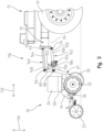
- Fig. 1 illustrates a planter 13 including a row unit 10 and a toolbar 12 to which the row unit 10 is indirectly coupled.
- the row unit 10 is configured to deliver commodity to an underlying surface.
- the planter 13 includes a plurality of row units mounted along a length of the toolbar 12.
- the planter 13 includes multiple toolbars (e.g., a forward toolbar and a rearward toolbar) spaced from one another in the fore-aft direction, each having row units coupled thereto.
- the fore-aft direction is shown by the arrow 112 in Fig. 1 .
- the toolbar 12 is supported above the underlying surface by a plurality of wheels, one of which (i.e., wheel 17) is shown in Fig. 1 .
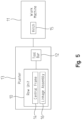
- the planter 13 is coupled to a work machine 11, such as a tractor, via a hitch 15.
- the work machine 11 includes a power unit such as a gas, diesel, or electric motor or a hybrid combination thereof that selectively distributes torque to move one or more wheels or a track assembly of the work machine 11.
- the hitch 15 provides a location to couple the planter 13 to a frame of the work machine 11. In this arrangement, the work machine 11 is configured to pull the planter 13 along the underlying surface.
- the hitch 15 may have a single or multi-point coupling configuration.
- the row unit 10 may be coupled directly to a toolbar, the frame of the work machine 11, or another portion of the work machine 11 with or without the hitch 15.
- the embodiments of the planter 13 and work machine 11 described herein are non-limiting examples suitable for use with the row unit 10, and it should be appreciated that the row unit 10 may be used with any planter and/or work machine suitable for advancing the row unit 10 along an underlying surface during an agricultural operation.
- the row unit 10 includes a main frame 61 coupled to the toolbar 12 by a linkage assembly 16.
- the linkage assembly 16 enables vertical (i.e., the direction indicated by the arrow 110) movement of the row unit 10 relative to the toolbar 12.
- the linkage assembly 16 is positioned between and pivotably coupled to the toolbar 12 and the row unit 10 such that the row unit 10 is configured to move vertically relative to the toolbar 12 to follow the contours of the underlying surface during an agricultural operation.
- the linkage assembly 16 is replaced by a linkage assembly 116.
- the linkage assembly 116 is similar to the linkage assembly 16 such that description of one applies equally to the other unless otherwise stated.
- the length of the linkage assembly 116 (in the fore-aft direction 112) is less than that of the linkage assembly 116.
- an actuator 162 associated with the linkage assembly 116 is arranged differently (e.g., relative to the corresponding lower arm 142) than an actuator 62 of the linkage assembly 16.
- the linkage assembly 16 includes a lower arm 42 that differs from a lower arm 142 of the linkage assembly 116, as described below.
- the linkage assemblies 16, 116 are substantially similar.
- a commodity e.g., seed or fertilizer
- a commodity meter 26 which releases the commodity for distribution to the underlying surface.
- the commodity is distributed to a furrow formed in the soil by a furrow opener coupled to a central frame 14 of the main frame 61.
- the furrow opener includes at least one disk 30 configured to contact the underlying surface to form the furrow.
- at least one gauge wheel 32 controls the depth of the furrow and is pivotably mounted to the central frame 14 via at least one strut 36.
- a closing wheel 33 is coupled to the central frame 14 and configured to close the furrow opened by the at least one disk 30 after the commodity is provided to the furrow.
- the linkage assembly 16 includes an upper arm 40 and the lower arm 42.
- the upper arm 40 and lower arm 42 are parallel to one another at all times.
- the upper arm 40 includes a forward end 44 pivotably coupled to the toolbar 12 at a first coupling point 46 and a rearward end 48 pivotably coupled to the row unit 10 at a third coupling point 50.
- the lower arm 42 includes a forward end 52 pivotably coupled to the toolbar 12 at a second coupling point 54 and a rearward end 56 pivotably coupled to the row unit 10 at a fourth coupling point 58.
- the upper arm 40 and the lower arm 42 are each coupled to an upper frame 60 of the row unit 10.
- the upper frame 60 is fixed relative to the central frame 14. In some embodiments, the upper frame 60 and the central frame 14 are both included in the main frame 61 of the row unit 10. In some embodiments, the upper frame 60 and the central frame 14 are single monolithic component of the row unit 10.
- the linkage assembly 116 includes an upper arm 140 and the lower arm 142. In some embodiments, the arms 140, 142 are parallel to one another at all times.
- the lower arm 142 includes a forward end 152 pivotably coupled to the toolbar 12 at the second coupling point 54 and a rearward end 156 pivotably coupled to the row unit 10 at the fourth coupling point 58. In the illustrative embodiment, the upper arm 140 and the lower arm 142 are each coupled to the upper frame 60 of the row unit 10.
- the lower arm 42, 142 of each linkage assembly 16, 116 includes a longitudinal axis 64 extending therethrough.
- a majority of the length (i.e., in the fore-aft direction 112) of each lower arm 42, 142 is symmetrical across opposite sides of the longitudinal axis 64.
- the lower arms 42, 142 each include standard portions 66, 166, respectively, that are symmetrical across opposite sides of the longitudinal axis 64.
- the standard portions 66, 166 each include the forward ends 52, 152 of the respective lower arms 42, 142.
- the longitudinal axis 64 of each lower arm 42, 142 is aligned with the second coupling point 54 and the fourth coupling point 58.
- the longitudinal axis 64 is aligned with a coupling point is that when viewed in a side elevation view as shown in Figs. 1 and 3 or a cross-sectional view as shown in Fig. 2 and 4 , the longitudinal axis 64 appears to intersect the coupling points 54, 58.
- the planter 13 includes the actuator 62 coupled to the linkage assembly 16.
- the planter 13 includes the actuator 162 coupled to the linkage assembly 116.
- the actuators 62, 162 are configured to retract to urge the row unit 10 downward relative to the underlying surface during an agricultural operation.
- the actuators 62, 162 are configured to extend within a first range of motion (e.g., a first distance) to urge the row unit 10 upward away from the underlying surface during an agricultural operation and extend further, beyond the first range of motion (e.g., a second distance greater than the first distance), to move the row unit 10 into a stowed position for travel, which is independent of the agricultural operation.
- a first range of motion e.g., a first distance
- the force available to extend the actuators 62, 162 is greater than the force available to retract the actuators 62, 162.
- the actuators 62, 162 each include the cylinder 68 and the piston 70, which is positioned partially within the cylinder 68.
- the piston 70 is configured to move relative to the cylinder 68 during extension and retraction of each actuator 62, 162.
- the actuators 62, 162 each include a first end 72 comprised by the piston 70 and a second end 74 comprised by the cylinder 68.
- the cylinder 68 includes a chamber 78 having a rod-side 80 configured to be pressurized to retract each actuator 62, 162 and a cylinder-side 82 configured to be pressurized to extend each actuator 62, 162.
- each actuator 62, 162 is pivotably coupled to the row unit 10 and corresponding upper arm 40, 140 at the third coupling point 50.
- the second end 74 of the actuator 62 is pivotably coupled to the lower arm 42 at a fifth coupling point 76 that is located between the second coupling point 54 and the fourth coupling point 58.
- the second end 74 of the actuator 162 is pivotably coupled to the lower arm 142 at a fifth coupling point 176 that is located between the second coupling point 54 and the fourth coupling point 58.
- a fifth coupling point e.g., 176 as being between the second coupling point 54 and the fourth coupling point 58 does not necessarily require vertical alignment of the fifth coupling point (e.g., 176) with the second coupling point 54 and the fourth coupling point 58. Between, in this context, means between in the fore-aft direction 112.
- each actuator 62, 162 is located between the respective fifth coupling point 76, 176 and the rod-side 80 of each actuator 62, 162.
- This arrangement allows for more force to be applied for extension of each actuator 62, 162 relative to retraction of each actuator 62, 162, which is important because, in some embodiments, movement of the row unit 10 to the stowed position requires more force than is needed for application of downforce to cause the row unit 10 to follow ground contours of the underlying surface.
- each actuator 62, 162 is positioned nearer to the row unit 10 than is the second end 74 of each actuator 62, 162 such that the actuator is sloped relative to the upper frame 60 of the row unit 10.
- each actuator 62, 162 is nearly parallel to the direction of an overall reaction force of the ground created as the row unit 10 moves along the underlying surface. This nearly parallel relationship reduces the variation in row unit downforce while the row unit 10 follows contours of the underlying surface during the agricultural operation.
- the row unit 10 moving through the soil in the fore-aft direction 112 creates a draft reaction force
- the weight of the row unit 10 and downforce in the vertical direction 110 applied by the row unit 10 creates a ground reaction force.
- the resultant force vector of the draft reaction force and the ground reaction force is referred to as the overall reaction force, and is nearly parallel with each actuator 62, 162.
- nearly parallel means within 20 degrees.
- nearly parallel means within 10 degrees.
- nearly parallel means within 5 degrees.
- the longitudinal axis 64 of the lower arm 42 is aligned with the fifth coupling point 76.
- the lower arm 42 comprises the standard portion 66 and a bumper portion 84, which includes the rearward end 56 of the lower arm 42.
- the standard portion 66 extends above and below the longitudinal axis 64 a distance D 1 .
- the bumper portion 84 is adjacent to the standard portion and extends above and below the longitudinal axis 64 a distance D 2 that is greater than the distance D 1 .
- the bumper portion 84 is configured to contact the upper frame 60 of the row unit 10 to limit pivoting movement of the row unit 10 relative to the linkage assembly 16.
- the fifth coupling point 76 is located on the standard portion 66 of the lower arm 52.
- the lower arm 142 comprises the standard portion 166 and a bumper portion 184, which includes the rearward end 156 of the lower arm 142.
- the standard portion 166 extends above and below the longitudinal axis 64 the distance D 1 .
- the bumper portion 184 is adjacent to the standard portion and extends below the longitudinal axis 64 a distance D 3 that is greater than the distance D 1 .
- the bumper portion 184 is configured to contact the upper frame 60 of the row unit 10 to limit pivoting movement of the row unit 10 relative to the linkage assembly 116. As shown in Figs.
- the fifth coupling point 176 is located on the bumper portion 184 and is below the longitudinal axis 64 of the lower arm 162. As such, the longitudinal axis 64 of the lower arm 142 is not aligned with the fifth coupling point 176. What is meant by the longitudinal axis 64 being not aligned with the fifth coupling point 176 is that when viewed in a side elevation view as shown in Fig. 3 or a cross-sectional view as shown in Fig. 4 , the longitudinal axis 64 appears to not intersect the coupling point 176. Referring again to Figs. 3-4 , the fifth coupling point 176 is positioned nearer to the fourth coupling point 58 than to the second coupling point 54.
- a first end of a downforce actuator associated with the row unit 10 may be pivotably coupled to the row unit 10 (e.g., the upper frame 60) at a location that is spaced apart from the third coupling point 50 while the second end of the downforce actuator is pivotably coupled to the lower arm 42 at a location between the second coupling point 54 and the fourth coupling point 58.
- the first end of the actuator (e.g., actuator 62, 162) is not pivotably coupled (nor otherwise directly coupled) to the upper arm.
- the first end of the actuator (e.g., actuator 62, 162) is pivotably coupled to the row unit 10 at a location that is between the third coupling point 50 and the fourth coupling point 58.
- the first end of the actuator (e.g., actuator 62, 162) is pivotably coupled to the row unit 10 at a location that is nearer to the third coupling point 50 than to the fourth coupling point 58.
- a method of moving the row unit 10 includes moving the planter over underlying soil during an agricultural operation such that a linkage assembly (e.g., linkage assembly 16, 116) coupled between the toolbar 12 and the row unit 10 pivots relative to the toolbar 12 and the row unit 10. Further, the method includes retracting an actuator (e.g., actuator 62, 162) to urge the row unit 10 downward relative to the underlying surface during the agricultural operation. Further, the method includes extending the actuator (e.g., actuator 62, 162) a first distance during the agricultural operation to lessen the downward force of the row unit 10.
- an actuator e.g., actuator 62, 162
- the method includes, subsequent to the agricultural operation, extending the actuator (e.g., actuator 62, 162) a second distance to move the row unit 10 to a stowed position for travel.
- extending the actuator (e.g., actuator 62, 162) the second distance subsequent to the agricultural operation includes applying more force than retracting the actuator (e.g., actuator 62, 162) during the agricultural operation.
Landscapes
- Life Sciences & Earth Sciences (AREA)
- Soil Sciences (AREA)
- Environmental Sciences (AREA)
- Agricultural Machines (AREA)
- Catching Or Destruction (AREA)
Abstract
A planter (13) for use in an agricultural operation is disclosed. The planter (13) comprising: a toolbar (12) supported above an underlying surface; a row unit (10) coupled to the toolbar (12) and configured to distribute commodity to the underlying surface; a linkage assembly (16, 116) including an upper arm (40) and a lower arm (42, 142) positioned below the upper arm (40), the upper arm (40) including a forward end (44) pivotably coupled to the toolbar (12) at a first coupling point (46) and a rearward end (48) pivotably coupled to the row unit (10) at a third coupling point (50), and the lower arm (42, 142) including a forward end (52) pivotably coupled to the toolbar (12) at a second coupling point (54) and a rearward end (56) pivotably coupled to the row unit (10) at a fourth coupling point (58); and an actuator (62, 162) including a first end (72) pivotably coupled to the row unit (10) and the upper arm (40) at the third coupling point (50) and a second end (74) pivotably coupled to the lower arm (42, 142) at a fifth coupling point (76) located between the second coupling point (54) and the fourth coupling point (58); wherein the actuator (62, 162) is configured to retract to urge the row unit (10) downward relative to the underlying surface.
Description
- The present disclosure relates to planters with row units, and more particularly, to linkage assemblies for row units of planters.
- Agricultural implements such as planters often have a plurality of row units coupled to a toolbar or other frame. The plurality of row units may be pulled behind a tractor or other work machine to provide commodity to an underlying surface. As the work machine travels along the underlying surface, row units may become positioned at undesirable locations or angles relative to the underlying surface. This may be caused by the arrangement of components of the row units or components of linkage assemblies that facilitate movement of the row units relative to the toolbar, for example.
- In an illustrative embodiment, a planter for use in an agricultural operation includes: a toolbar supported above an underlying surface; a row unit coupled to the toolbar and configured to distribute commodity to the underlying surface; a linkage assembly including an upper arm and a lower arm positioned below the upper arm, the upper arm including a forward end pivotably coupled to the toolbar at a first coupling point and a rearward end pivotably coupled to the row unit at a third coupling point, and the lower arm including a forward end pivotably coupled to the toolbar at a second coupling point and a rearward end pivotably coupled to the row unit at a fourth coupling point; and an actuator including a first end pivotably coupled to the row unit and the upper arm at the third coupling point and a second end pivotably coupled to the lower arm at a fifth coupling point located between the second coupling point and the fourth coupling point; wherein the actuator is configured to retract to urge the row unit downward relative to the underlying surface.
- In some embodiments, the actuator includes a cylinder and a piston positioned partially within the cylinder and configured to move relative to the cylinder during extension and retraction of the actuator. In some embodiments, the piston is coupled to both the row unit and the upper arm at the third coupling point and the cylinder is coupled to the lower arm at the fifth coupling point. In some embodiments, the cylinder includes a chamber having a rod-side configured to be pressurized to retract the actuator and a cylinder-side configured to be pressurized to extend the actuator; and the cylinder-side is located between the fifth coupling point and the rod-side.
- In some embodiments, the upper arm and the lower arm are parallel to each other at all times during the agricultural operation. In some embodiments, the lower arm includes a longitudinal axis that extends therethrough and is aligned with the second coupling point and the fourth coupling point.
- In some embodiments, a majority of a length of the lower arm is symmetrical across opposite sides of the longitudinal axis. In some embodiments, the longitudinal axis is aligned with the fifth coupling point. In some embodiments, the longitudinal axis is not aligned with the fifth coupling point. In some embodiments, the fifth coupling point is positioned below the longitudinal axis. In some embodiments, the lower arm includes a standard portion extending below the longitudinal axis a first distance and a bumper portion adjacent to the standard portion and extending below the longitudinal axis a second distance that is greater than the first distance; and the bumper portion is configured to contact the row unit to limit pivoting movement of the row unit relative to the linkage assembly. In some embodiments, the fifth coupling point is located on the bumper portion. In some embodiments, the fifth coupling point is positioned nearer to the fourth coupling point than to the second coupling point.
- In some embodiments, the row unit includes a main frame to which the linkage assembly is coupled; and the row unit includes at least one disk coupled the main frame and configured to form a furrow in the underlying surface that receives the commodity distributed by the row unit.
- In some embodiments, the actuator is configured to extend to urge the row unit upward away from the underlying surface into a position for travel independent of the agricultural operation. In some embodiments, the force available to extend the actuator is greater than the force available to retract the actuator. In some embodiments, the force required and used to extend the actuator to move the row unit into a position for travel independent of the agricultural operation is greater than the force required and used to retract the actuator.
- In another illustrative embodiment, a planter for use in an agricultural operation includes: a toolbar supported above an underlying surface; a row unit coupled to the toolbar and configured to distribute commodity to the underlying surface; a linkage assembly including an upper arm and a lower arm positioned below the upper arm, the upper arm including a forward end pivotably coupled to the toolbar at a first coupling point and a rearward end pivotably coupled to the row unit at a third coupling point, and the lower arm including a forward end pivotably coupled to the toolbar at a second coupling point and a rearward end pivotably coupled to the row unit at a fourth coupling point; and an actuator including a first end pivotably coupled to the row unit and a second end pivotably coupled to the lower arm at a fifth coupling point located between the second coupling point and the fourth coupling point; wherein the actuator is configured to retract to urge the row unit downward relative to the underlying surface.
- In some embodiments, the first end of the actuator is pivotably coupled to the upper arm. In some embodiments, the first end of the actuator is not pivotably coupled to the upper arm. In some embodiments, the first end of the actuator is coupled to the row unit at a location spaced apart from the third coupling point. In some embodiments, the first end of the actuator is pivotably coupled to the row unit at a location that is between the third coupling point and the fourth coupling point. In some embodiments, the first end of the actuator is pivotably coupled to the row unit at a location that is nearer to the third coupling point than to the fourth coupling point.
- In another illustrative embodiment, a method of moving a row unit that is configured to distribute commodity during an agricultural operation includes: moving a planter having a toolbar over underlying soil during the agricultural operation such that a linkage assembly coupled between the toolbar and the row unit pivots relative to the toolbar and the row unit; retracting an actuator to urge the row unit downward relative to the underlying surface, the actuator including: a first end pivotably coupled to the row unit and the upper arm at a coupling point where the row unit is pivotably coupled to the upper arm, and a second end pivotably coupled to the lower arm at a coupling point located between the row unit and the toolbar; and extending the actuator to urge the row unit upward away from the underlying surface to move the row unit into a position for travel independent of the agricultural operation.
- The above-mentioned aspects of the present disclosure and the manner of obtaining them will become more apparent and the disclosure itself will be better understood by reference to the following description of the embodiments of the disclosure, taken in conjunction with the accompanying drawings, wherein:
-
Fig. 1 is a side elevation view of a row unit moveably coupled to a toolbar of a planter via a linkage assembly such that the row unit is configured to follow ground contours of an underlying surface during an agricultural operation; -
Fig. 2 is cross-sectional view of the linkage assembly ofFig. 1 ; -
Fig. 3 is a side elevation view of the row unit ofFig. 1 moveably coupled to the toolbar of the planter ofFig. 1 via another linkage assembly, having a lesser length than the linkage assembly ofFig. 1 ; -
Fig. 4 is cross-sectional view of the linkage assembly ofFig. 3 ; and -
Fig. 5 is a diagrammatic view of the planter ofFig. 1 and a work machine that is configured to move the planter along the underlying surface during the agricultural operation. - Corresponding reference numerals indicate corresponding parts throughout the several views.
- The embodiments of the present disclosure described below are not exhaustive and do not limit the disclosure to the precise forms in the following detailed description. Rather, the embodiments are chosen and described so that others skilled in the art may appreciate and understand the principles and practices of the present disclosure.
-
Fig. 1 illustrates aplanter 13 including arow unit 10 and atoolbar 12 to which therow unit 10 is indirectly coupled. Therow unit 10 is configured to deliver commodity to an underlying surface. In some embodiments, theplanter 13 includes a plurality of row units mounted along a length of thetoolbar 12. In some embodiments, theplanter 13 includes multiple toolbars (e.g., a forward toolbar and a rearward toolbar) spaced from one another in the fore-aft direction, each having row units coupled thereto. The fore-aft direction is shown by thearrow 112 inFig. 1 . It should be appreciated that reference to therow unit 10 is applicable to each row unit of theplanter 13 regardless of the number or specific arrangement of the row units on theplanter 13. In the illustrative embodiment, thetoolbar 12 is supported above the underlying surface by a plurality of wheels, one of which (i.e., wheel 17) is shown inFig. 1 . - As shown in
Fig. 5 , in the illustrative embodiment, theplanter 13 is coupled to awork machine 11, such as a tractor, via ahitch 15. In some embodiments, thework machine 11 includes a power unit such as a gas, diesel, or electric motor or a hybrid combination thereof that selectively distributes torque to move one or more wheels or a track assembly of thework machine 11. Thehitch 15 provides a location to couple theplanter 13 to a frame of thework machine 11. In this arrangement, thework machine 11 is configured to pull theplanter 13 along the underlying surface. Thehitch 15 may have a single or multi-point coupling configuration. In some embodiments, therow unit 10 may be coupled directly to a toolbar, the frame of thework machine 11, or another portion of thework machine 11 with or without thehitch 15. The embodiments of theplanter 13 andwork machine 11 described herein are non-limiting examples suitable for use with therow unit 10, and it should be appreciated that therow unit 10 may be used with any planter and/or work machine suitable for advancing therow unit 10 along an underlying surface during an agricultural operation. - Referring again to
Fig. 1 , in the illustrative embodiment, therow unit 10 includes amain frame 61 coupled to thetoolbar 12 by alinkage assembly 16. Thelinkage assembly 16 enables vertical (i.e., the direction indicated by the arrow 110) movement of therow unit 10 relative to thetoolbar 12. Thelinkage assembly 16 is positioned between and pivotably coupled to thetoolbar 12 and therow unit 10 such that therow unit 10 is configured to move vertically relative to thetoolbar 12 to follow the contours of the underlying surface during an agricultural operation. - In some embodiments (e.g.,
Figs. 3-4 ), thelinkage assembly 16 is replaced by alinkage assembly 116. Thelinkage assembly 116 is similar to thelinkage assembly 16 such that description of one applies equally to the other unless otherwise stated. The length of the linkage assembly 116 (in the fore-aft direction 112) is less than that of thelinkage assembly 116. Based at least in part on the lesser length of thelinkage assembly 116, anactuator 162 associated with thelinkage assembly 116 is arranged differently (e.g., relative to the corresponding lower arm 142) than anactuator 62 of thelinkage assembly 16. Further, thelinkage assembly 16 includes alower arm 42 that differs from alower arm 142 of thelinkage assembly 116, as described below. As to other aspects, thelinkage assemblies - In the illustrative embodiment, a commodity (e.g., seed or fertilizer) is stored in a
hopper 24 and provided to acommodity meter 26, which releases the commodity for distribution to the underlying surface. In the illustrative embodiment, the commodity is distributed to a furrow formed in the soil by a furrow opener coupled to acentral frame 14 of themain frame 61. The furrow opener includes at least onedisk 30 configured to contact the underlying surface to form the furrow. In the illustrative embodiment, at least onegauge wheel 32 controls the depth of the furrow and is pivotably mounted to thecentral frame 14 via at least onestrut 36. Aclosing wheel 33 is coupled to thecentral frame 14 and configured to close the furrow opened by the at least onedisk 30 after the commodity is provided to the furrow. - As shown in
Figs. 1-2 , thelinkage assembly 16 includes anupper arm 40 and thelower arm 42. In some embodiments, theupper arm 40 andlower arm 42 are parallel to one another at all times. Theupper arm 40 includes aforward end 44 pivotably coupled to thetoolbar 12 at afirst coupling point 46 and arearward end 48 pivotably coupled to therow unit 10 at athird coupling point 50. Similarly, thelower arm 42 includes aforward end 52 pivotably coupled to thetoolbar 12 at asecond coupling point 54 and arearward end 56 pivotably coupled to therow unit 10 at afourth coupling point 58. In the illustrative embodiment, theupper arm 40 and thelower arm 42 are each coupled to anupper frame 60 of therow unit 10. In the illustrative embodiment, theupper frame 60 is fixed relative to thecentral frame 14. In some embodiments, theupper frame 60 and thecentral frame 14 are both included in themain frame 61 of therow unit 10. In some embodiments, theupper frame 60 and thecentral frame 14 are single monolithic component of therow unit 10. Referring now toFigs. 3-4 , thelinkage assembly 116 includes anupper arm 140 and thelower arm 142. In some embodiments, thearms lower arm 142 includes aforward end 152 pivotably coupled to thetoolbar 12 at thesecond coupling point 54 and arearward end 156 pivotably coupled to therow unit 10 at thefourth coupling point 58. In the illustrative embodiment, theupper arm 140 and thelower arm 142 are each coupled to theupper frame 60 of therow unit 10. - As shown in
Figs. 1-4 , thelower arm linkage assembly longitudinal axis 64 extending therethrough. In the illustrative embodiments, a majority of the length (i.e., in the fore-aft direction 112) of eachlower arm longitudinal axis 64. For example, thelower arms standard portions longitudinal axis 64. In the illustrative embodiments, thestandard portions lower arms - In the illustrative embodiments, the
longitudinal axis 64 of eachlower arm second coupling point 54 and thefourth coupling point 58. What is meant by thelongitudinal axis 64 being aligned with a coupling point is that when viewed in a side elevation view as shown inFigs. 1 and3 or a cross-sectional view as shown inFig. 2 and4 , thelongitudinal axis 64 appears to intersect the coupling points 54, 58. - In the illustrative embodiment shown in
Figs. 1-2 , theplanter 13 includes theactuator 62 coupled to thelinkage assembly 16. In the illustrative embodiment shown inFigs. 3-4 , theplanter 13 includes theactuator 162 coupled to thelinkage assembly 116. In the illustrative embodiments, theactuators row unit 10 downward relative to the underlying surface during an agricultural operation. In the illustrative embodiments, theactuators row unit 10 upward away from the underlying surface during an agricultural operation and extend further, beyond the first range of motion (e.g., a second distance greater than the first distance), to move therow unit 10 into a stowed position for travel, which is independent of the agricultural operation. In the illustrative embodiments, due to the orientation of theactuators 62, 162 (e.g., position of apiston 70 relative to a cylinder 68), the force available to extend theactuators actuators - Referring now to
Figs. 2 and4 , theactuators cylinder 68 and thepiston 70, which is positioned partially within thecylinder 68. Thepiston 70 is configured to move relative to thecylinder 68 during extension and retraction of each actuator 62, 162. In the illustrative embodiments, theactuators first end 72 comprised by thepiston 70 and asecond end 74 comprised by thecylinder 68. Thecylinder 68 includes achamber 78 having a rod-side 80 configured to be pressurized to retract each actuator 62, 162 and a cylinder-side 82 configured to be pressurized to extend each actuator 62, 162. - As shown in
Figs 1-4 , thefirst end 72 of each actuator 62, 162 is pivotably coupled to therow unit 10 and correspondingupper arm third coupling point 50. In the illustrative embodiment shown inFigs. 1-2 , thesecond end 74 of theactuator 62 is pivotably coupled to thelower arm 42 at afifth coupling point 76 that is located between thesecond coupling point 54 and thefourth coupling point 58. In the illustrative embodiment shown inFigs. 3-4 , thesecond end 74 of theactuator 162 is pivotably coupled to thelower arm 142 at afifth coupling point 176 that is located between thesecond coupling point 54 and thefourth coupling point 58. It should be appreciated that referring to a fifth coupling point (e.g., 176) as being between thesecond coupling point 54 and thefourth coupling point 58 does not necessarily require vertical alignment of the fifth coupling point (e.g., 176) with thesecond coupling point 54 and thefourth coupling point 58. Between, in this context, means between in the fore-aft direction 112. - As shown in
Figs. 1-4 , the cylinder-side 82 of each actuator 62, 162 is located between the respectivefifth coupling point side 80 of each actuator 62, 162. This arrangement allows for more force to be applied for extension of each actuator 62, 162 relative to retraction of each actuator 62, 162, which is important because, in some embodiments, movement of therow unit 10 to the stowed position requires more force than is needed for application of downforce to cause therow unit 10 to follow ground contours of the underlying surface. - As shown in
Figs. 1-4 , thefirst end 72 of each actuator 62, 162 is positioned nearer to therow unit 10 than is thesecond end 74 of each actuator 62, 162 such that the actuator is sloped relative to theupper frame 60 of therow unit 10. In this sloped orientation, in some embodiments, each actuator 62, 162 is nearly parallel to the direction of an overall reaction force of the ground created as therow unit 10 moves along the underlying surface. This nearly parallel relationship reduces the variation in row unit downforce while therow unit 10 follows contours of the underlying surface during the agricultural operation. Therow unit 10 moving through the soil in the fore-aft direction 112 creates a draft reaction force, and the weight of therow unit 10 and downforce in thevertical direction 110 applied by therow unit 10 creates a ground reaction force. The resultant force vector of the draft reaction force and the ground reaction force is referred to as the overall reaction force, and is nearly parallel with each actuator 62, 162. In some embodiments, nearly parallel means within 20 degrees. In some embodiments nearly parallel means within 10 degrees. In some embodiments nearly parallel means within 5 degrees. - Referring now to
Fig. 2 , thelongitudinal axis 64 of thelower arm 42 is aligned with thefifth coupling point 76. Thelower arm 42 comprises thestandard portion 66 and abumper portion 84, which includes therearward end 56 of thelower arm 42. In the illustrative embodiment, thestandard portion 66 extends above and below the longitudinal axis 64 a distance D1. Thebumper portion 84 is adjacent to the standard portion and extends above and below the longitudinal axis 64 a distance D2 that is greater than the distance D1. In the illustrative embodiment, as therow unit 10 pivots relative to thelinkage assembly 16, thebumper portion 84 is configured to contact theupper frame 60 of therow unit 10 to limit pivoting movement of therow unit 10 relative to thelinkage assembly 16. In the illustrative embodiment, thefifth coupling point 76 is located on thestandard portion 66 of thelower arm 52. - Referring now to
Figs. 3-4 , thelower arm 142 comprises thestandard portion 166 and abumper portion 184, which includes therearward end 156 of thelower arm 142. In the illustrative embodiment, thestandard portion 166 extends above and below thelongitudinal axis 64 the distance D1. Thebumper portion 184 is adjacent to the standard portion and extends below the longitudinal axis 64 a distance D3 that is greater than the distance D1. In the illustrative embodiment, as therow unit 10 pivots relative to thelinkage assembly 116, thebumper portion 184 is configured to contact theupper frame 60 of therow unit 10 to limit pivoting movement of therow unit 10 relative to thelinkage assembly 116. As shown inFigs. 3-4 , in the illustrative embodiment, thefifth coupling point 176 is located on thebumper portion 184 and is below thelongitudinal axis 64 of thelower arm 162. As such, thelongitudinal axis 64 of thelower arm 142 is not aligned with thefifth coupling point 176. What is meant by thelongitudinal axis 64 being not aligned with thefifth coupling point 176 is that when viewed in a side elevation view as shown inFig. 3 or a cross-sectional view as shown inFig. 4 , thelongitudinal axis 64 appears to not intersect thecoupling point 176. Referring again toFigs. 3-4 , thefifth coupling point 176 is positioned nearer to thefourth coupling point 58 than to thesecond coupling point 54. - This disclosure contemplates other embodiments wherein the downforce actuator associated with the row unit 10 (e.g.,
actuator 62, 162) is nearly parallel or otherwise sloped similarly to the overall reaction force applied to therow unit 10 during an agricultural operation. For example, in some embodiments, a first end of a downforce actuator associated with therow unit 10 may be pivotably coupled to the row unit 10 (e.g., the upper frame 60) at a location that is spaced apart from thethird coupling point 50 while the second end of the downforce actuator is pivotably coupled to thelower arm 42 at a location between thesecond coupling point 54 and thefourth coupling point 58. In other words, in some embodiments, the first end of the actuator (e.g.,actuator 62, 162) is not pivotably coupled (nor otherwise directly coupled) to the upper arm. In some embodiments, the first end of the actuator (e.g.,actuator 62, 162) is pivotably coupled to therow unit 10 at a location that is between thethird coupling point 50 and thefourth coupling point 58. In some embodiments, the first end of the actuator (e.g.,actuator 62, 162) is pivotably coupled to therow unit 10 at a location that is nearer to thethird coupling point 50 than to thefourth coupling point 58. - In use, a method of moving the
row unit 10 includes moving the planter over underlying soil during an agricultural operation such that a linkage assembly (e.g.,linkage assembly 16, 116) coupled between thetoolbar 12 and therow unit 10 pivots relative to thetoolbar 12 and therow unit 10. Further, the method includes retracting an actuator (e.g.,actuator 62, 162) to urge therow unit 10 downward relative to the underlying surface during the agricultural operation. Further, the method includes extending the actuator (e.g.,actuator 62, 162) a first distance during the agricultural operation to lessen the downward force of therow unit 10. Further, the method includes, subsequent to the agricultural operation, extending the actuator (e.g.,actuator 62, 162) a second distance to move therow unit 10 to a stowed position for travel. In some embodiments, extending the actuator (e.g.,actuator 62, 162) the second distance subsequent to the agricultural operation includes applying more force than retracting the actuator (e.g.,actuator 62, 162) during the agricultural operation. - While this disclosure has been described with respect to at least one embodiment, the present disclosure can be further modified within the spirit and scope of this disclosure. This application is therefore intended to cover any variations, uses, or adaptations of the disclosure using its general principles. Further, this application is intended to cover such departures from the present disclosure as come within known or customary practice in the art to which this disclosure pertains and which fall within the limits of the appended claims.
Claims (15)
- A planter (13) for use in an agricultural operation comprising:a toolbar (12) supported above an underlying surface;a row unit (10) coupled to the toolbar (12) and configured to distribute commodity to the underlying surface;a linkage assembly (16, 116) including an upper arm (40) and a lower arm (42, 142) positioned below the upper arm (40), the upper arm (40) including a forward end (44) pivotably coupled to the toolbar (12) at a first coupling point (46) and a rearward end (48) pivotably coupled to the row unit (10) at a third coupling point (50), and the lower arm (42, 142) including a forward end (52) pivotably coupled to the toolbar (12) at a second coupling point (54) and a rearward end (56) pivotably coupled to the row unit (10) at a fourth coupling point (58); andan actuator (62, 162) including a first end (72) pivotably coupled to the row unit (10) and the upper arm (40) at the third coupling point (50) and a second end (74) pivotably coupled to the lower arm (42, 142) at a fifth coupling point (76) located between the second coupling point (54) and the fourth coupling point (58);wherein the actuator (62, 162) is configured to retract to urge the row unit (10) downward relative to the underlying surface.
- The planter (13) of claim 1, wherein the actuator (62, 162) includes a cylinder (68) and a piston (70) positioned partially within the cylinder (68) and configured to move relative to the cylinder (68) during extension and retraction of the actuator (62, 162).
- The planter (13) of claim 2, wherein the piston (70) is coupled to both the row unit (10) and the upper arm (40) at the third coupling point (50) and the cylinder (68) is coupled to the lower arm (42, 142) at the fifth coupling point (76, 176).
- The planter (13) of claim 2 or 3, wherein the cylinder (68) includes a chamber (78) having a rod-side (80) configured to be pressurized to retract the actuator (62, 162) and a cylinder-side (82) configured to be pressurized to extend the actuator (62, 162); and
wherein the cylinder-side (82) is located between the fifth coupling point (76) and the rod-side (80). - The planter (13) of one of the claims 1 to 4, wherein upper arm (40) and the lower arm (42, 142) are parallel to each other at all times during the agricultural operation.
- The planter (13) of one of the claims 1 to 5, wherein the lower arm (42, 142) includes a longitudinal axis (64) that extends therethrough and is aligned with the second coupling point (54) and the fourth coupling point (58).
- The planter (13) of one of the claims 1 to 6, wherein a majority of a length of the lower arm (42, 142) is symmetrical across opposite sides of the longitudinal axis (64).
- The planter (13) of one of the claims 1 to 7, wherein the longitudinal axis (64) is aligned with the fifth coupling point (76).
- The planter (13) of one of the claims 1 to 8, wherein the longitudinal axis (64) is not aligned with the fifth coupling point (176).
- The planter (13) of one of the claims 1 to 9, wherein the fifth coupling point (176) is positioned below the longitudinal axis (64).
- The planter (13) of one of the claims 1 to 10, wherein the lower arm (42, 142) includes a standard portion (66, 166) extending below the longitudinal axis (64) a first distance (D1) and a bumper portion (84, 184) adjacent to the standard portion (66, 166) and extending below the longitudinal axis (64) a second distance (D2) that is greater than the first distance (D1); and
wherein the bumper portion (84,184) is configured to contact the row unit (10) to limit pivoting movement of the row unit (10) relative to the linkage assembly (16, 116). - The planter (13) of one of the claims 1 to 11, wherein the fifth coupling point (176) is located on the bumper portion (184).
- The planter (13) of one of the claims 1 to 12, wherein the fifth coupling point (176) is positioned nearer to the fourth coupling point (58) than to the second coupling point (54).
- The planter (13) of one of the claims 1 to 13, wherein the row unit (10) includes a main frame (61) to which the linkage assembly (16, 116) is coupled; and
wherein the row unit (10) includes at least one disk (30) coupled to the main frame (61) and configured to form a furrow in the underlying surface that receives the commodity distributed by the row unit (10). - The planter (13) of one of the claims 1 to 14, wherein the actuator (62, 162) is configured to extend to urge the row unit (10) upward away from the underlying surface into a position for travel independent of the agricultural operation; and
wherein the force available to extend the actuator (62, 162) is greater than the force available to retract the actuator (62, 162).
Applications Claiming Priority (1)
| Application Number | Priority Date | Filing Date | Title |
|---|---|---|---|
| US18/543,394 US20250194456A1 (en) | 2023-12-18 | 2023-12-18 | Row unit suspension system and method |
Publications (1)
| Publication Number | Publication Date |
|---|---|
| EP4573867A1 true EP4573867A1 (en) | 2025-06-25 |
Family
ID=93705006
Family Applications (1)
| Application Number | Title | Priority Date | Filing Date |
|---|---|---|---|
| EP24215742.8A Pending EP4573867A1 (en) | 2023-12-18 | 2024-11-27 | Planter |
Country Status (3)
| Country | Link |
|---|---|
| US (1) | US20250194456A1 (en) |
| EP (1) | EP4573867A1 (en) |
| AU (1) | AU2024264562A1 (en) |
Citations (4)
| Publication number | Priority date | Publication date | Assignee | Title |
|---|---|---|---|---|
| US20130306337A1 (en) * | 2010-09-15 | 2013-11-21 | Dawn Equipment Company | Agricultural Apparatus With Hydraulic Cylinder And Manifold For A Row Unit |
| US20130319700A1 (en) * | 2011-02-18 | 2013-12-05 | Maschio Gaspardo S.p.A | Seed drill with multi-row sowing elements |
| US20220053688A1 (en) * | 2018-12-14 | 2022-02-24 | Amazonen-Werke H. Dreyer SE & Co. KG | Sowing machine having individual coulter pressure control |
| US20220295690A1 (en) * | 2021-03-16 | 2022-09-22 | Cnh Industrial Canada, Ltd. | Location-based control system for an agricultural implement |
Family Cites Families (29)
| Publication number | Priority date | Publication date | Assignee | Title |
|---|---|---|---|---|
| US2685384A (en) * | 1948-12-18 | 1954-08-03 | Allis Chalmers Mfg Co | Planter attachment for tractors |
| US2797629A (en) * | 1955-01-10 | 1957-07-02 | Leon O Kelley | Pivoted shank subsoil contour plow |
| US3032903A (en) * | 1959-01-20 | 1962-05-08 | Nat Res Dev | Mole plow supporting means |
| US3450074A (en) * | 1967-02-01 | 1969-06-17 | Agri Tek Inc | Seed planter for depositing fine seeds at controlled depth |
| US3527308A (en) * | 1967-06-09 | 1970-09-08 | Gen Motors Corp | Ripper attachment for tractor |
| US3454285A (en) * | 1967-08-11 | 1969-07-08 | Winpower Mfg Co | Offset actuated hitch |
| US3592273A (en) * | 1968-01-18 | 1971-07-13 | William E Martin | Bodily attachable bulldozing assembly for tractors |
| US3552497A (en) * | 1968-05-09 | 1971-01-05 | Caterpillar Tractor Co | Unitized side-by-side tractor and ripper combination |
| US3738432A (en) * | 1971-05-24 | 1973-06-12 | L Kelley | Ripper plow assembly for converting parallel lift to radial lift |
| US4033417A (en) * | 1974-04-10 | 1977-07-05 | Maschinenfabrik Rau Ohg | Agricultural machine |
| NL7509938A (en) * | 1975-08-22 | 1977-02-24 | Lely Nv C Van Der | AGRICULTURAL IMPLEMENT. |
| US4046200A (en) * | 1975-10-28 | 1977-09-06 | Excel Industries, Inc. | Lawn edger attachment |
| FR2347493A1 (en) * | 1976-04-06 | 1977-11-04 | Pelsy Gilles | OSCILLATING TOOTH DRAINAGE UNIT |
| US4074768A (en) * | 1976-08-30 | 1978-02-21 | Caterpillar Tractor Co. | Blade support and control arrangement for a motor grader |
| US4142817A (en) * | 1978-01-19 | 1979-03-06 | Germain Lazure | Plow for use in laying drain-tile |
| CA1075479A (en) * | 1978-01-20 | 1980-04-15 | Anthony Paladino | Plow or digging machine automatic blade adjusting and locking system |
| US4466491A (en) * | 1982-06-30 | 1984-08-21 | Tower Douglass G | Apparatus for removing rocks and objects |
| US5461995A (en) * | 1994-02-25 | 1995-10-31 | Dean A. Winterton | Rotary row cleaner with reversible spring |
| US5555824A (en) * | 1995-01-31 | 1996-09-17 | Case Corporation | Operator controlled pressure applicator for the furrow forming mechanism of a seed planter |
| GB9506469D0 (en) * | 1995-03-29 | 1995-05-17 | Kverneland Klepp As | Towable agricultural implement |
| US7111566B2 (en) * | 2003-12-09 | 2006-09-26 | Cnh America Llc | Seed planter including vertical positioner with locking member |
| US7980186B2 (en) * | 2009-05-21 | 2011-07-19 | Cnh Canada, Ltd. | Soil shaping system for precision ground engaging implement |
| US8505473B1 (en) * | 2010-01-14 | 2013-08-13 | Howard D. Martin | Paired single disc opener unit |
| US8544398B2 (en) * | 2010-09-15 | 2013-10-01 | Dawn Equipment Company | Hydraulic down pressure control system for closing wheels of an agricultural implement |
| EP2466014B1 (en) * | 2010-12-14 | 2020-05-27 | Caterpillar, Inc. | Linkage arrangement |
| RU2576457C2 (en) * | 2011-04-27 | 2016-03-10 | Кинз Мэньюфэкчеринг, Инк. | System regulating force directed downward and/or upward |
| JP5602929B1 (en) * | 2013-11-08 | 2014-10-08 | 株式会社小松製作所 | Motor grader ripper device and motor grader having the same |
| US9357692B2 (en) * | 2014-06-04 | 2016-06-07 | Cnh Industrial America Llc | Depth adjustment for controlling planting depth |
| CA3238055A1 (en) * | 2016-12-16 | 2018-06-21 | Agco Corporation | Implement contouring toolbar |
-
2023
- 2023-12-18 US US18/543,394 patent/US20250194456A1/en active Pending
-
2024
- 2024-11-12 AU AU2024264562A patent/AU2024264562A1/en active Pending
- 2024-11-27 EP EP24215742.8A patent/EP4573867A1/en active Pending
Patent Citations (4)
| Publication number | Priority date | Publication date | Assignee | Title |
|---|---|---|---|---|
| US20130306337A1 (en) * | 2010-09-15 | 2013-11-21 | Dawn Equipment Company | Agricultural Apparatus With Hydraulic Cylinder And Manifold For A Row Unit |
| US20130319700A1 (en) * | 2011-02-18 | 2013-12-05 | Maschio Gaspardo S.p.A | Seed drill with multi-row sowing elements |
| US20220053688A1 (en) * | 2018-12-14 | 2022-02-24 | Amazonen-Werke H. Dreyer SE & Co. KG | Sowing machine having individual coulter pressure control |
| US20220295690A1 (en) * | 2021-03-16 | 2022-09-22 | Cnh Industrial Canada, Ltd. | Location-based control system for an agricultural implement |
Also Published As
| Publication number | Publication date |
|---|---|
| US20250194456A1 (en) | 2025-06-19 |
| AU2024264562A1 (en) | 2025-07-03 |
Similar Documents
| Publication | Publication Date | Title |
|---|---|---|
| US8028759B2 (en) | Prescision hoe opener with swing link between cylinder and shank | |
| US7574969B1 (en) | Precision hoe opener and packer wheel assembly | |
| US10729054B2 (en) | Tracked agricultural implement having a caster wheel assembly | |
| US8434417B2 (en) | Soil shaping system for precision ground engaging implement | |
| US8100193B2 (en) | Adjustable packer wheel seeding system and method | |
| US7578246B2 (en) | Precision hoe opener with draft force compensation | |
| CA2927775A1 (en) | Mounted implement weight transfer | |
| US8011440B2 (en) | Precision hoe opener assembly with adjustable packer wheel location | |
| US20250194456A1 (en) | Row unit suspension system and method | |
| US7798244B2 (en) | Precision hoe opener with swing link and biasing member | |
| US2756662A (en) | Disc opener suspension | |
| US20160143209A1 (en) | Reducing wheel forces on a field surface | |
| US6386125B1 (en) | Seed drill | |
| US20210368668A1 (en) | Agricultural implement having a wing wheel linkage assembly | |
| US2780478A (en) | Hitch mechanism for connecting implements in tandem | |
| BR102024017750A2 (en) | PLANTER FOR USE IN AN AGRICULTURAL OPERATION | |
| US20260137020A1 (en) | Automatic closing wheel system | |
| US2290244A (en) | Implement attachment for tractors | |
| CA2648445C (en) | Precision hoe opener with draft force compensation | |
| CA2871836C (en) | Reducing wheel forces on a field surface | |
| CA2643870A1 (en) | Precision hoe opener with swing link and biasing member | |
| CA2643867A1 (en) | Precision hoe opener with swing link between cylinder and shank | |
| BR102019002496B1 (en) | AGRICULTURAL IMPLEMENT |
Legal Events
| Date | Code | Title | Description |
|---|---|---|---|
| PUAI | Public reference made under article 153(3) epc to a published international application that has entered the european phase |
Free format text: ORIGINAL CODE: 0009012 |
|
| STAA | Information on the status of an ep patent application or granted ep patent |
Free format text: STATUS: THE APPLICATION HAS BEEN PUBLISHED |
|
| AK | Designated contracting states |
Kind code of ref document: A1 Designated state(s): AL AT BE BG CH CY CZ DE DK EE ES FI FR GB GR HR HU IE IS IT LI LT LU LV MC ME MK MT NL NO PL PT RO RS SE SI SK SM TR |
|
| STAA | Information on the status of an ep patent application or granted ep patent |
Free format text: STATUS: REQUEST FOR EXAMINATION WAS MADE |
|
| 17P | Request for examination filed |
Effective date: 20260102 |