EP4572328A1 - Earphone - Google Patents
Earphone Download PDFInfo
- Publication number
- EP4572328A1 EP4572328A1 EP23943946.6A EP23943946A EP4572328A1 EP 4572328 A1 EP4572328 A1 EP 4572328A1 EP 23943946 A EP23943946 A EP 23943946A EP 4572328 A1 EP4572328 A1 EP 4572328A1
- Authority
- EP
- European Patent Office
- Prior art keywords
- wall portion
- sound guiding
- bottom wall
- guiding member
- headphone
- Prior art date
- Legal status (The legal status is an assumption and is not a legal conclusion. Google has not performed a legal analysis and makes no representation as to the accuracy of the status listed.)
- Pending
Links
Images



Classifications
-
- H—ELECTRICITY
- H04—ELECTRIC COMMUNICATION TECHNIQUE
- H04R—LOUDSPEAKERS, MICROPHONES, GRAMOPHONE PICK-UPS OR LIKE ACOUSTIC ELECTROMECHANICAL TRANSDUCERS; ELECTRIC HEARING AIDS; PUBLIC ADDRESS SYSTEMS
- H04R1/00—Details of transducers, loudspeakers or microphones
- H04R1/10—Earpieces; Attachments therefor ; Earphones; Monophonic headphones
- H04R1/1008—Earpieces of the supra-aural or circum-aural type
-
- H—ELECTRICITY
- H04—ELECTRIC COMMUNICATION TECHNIQUE
- H04R—LOUDSPEAKERS, MICROPHONES, GRAMOPHONE PICK-UPS OR LIKE ACOUSTIC ELECTROMECHANICAL TRANSDUCERS; ELECTRIC HEARING AIDS; PUBLIC ADDRESS SYSTEMS
- H04R1/00—Details of transducers, loudspeakers or microphones
- H04R1/10—Earpieces; Attachments therefor ; Earphones; Monophonic headphones
- H04R1/1033—Cables or cables storage, e.g. cable reels
-
- H—ELECTRICITY
- H04—ELECTRIC COMMUNICATION TECHNIQUE
- H04R—LOUDSPEAKERS, MICROPHONES, GRAMOPHONE PICK-UPS OR LIKE ACOUSTIC ELECTROMECHANICAL TRANSDUCERS; ELECTRIC HEARING AIDS; PUBLIC ADDRESS SYSTEMS
- H04R1/00—Details of transducers, loudspeakers or microphones
- H04R1/10—Earpieces; Attachments therefor ; Earphones; Monophonic headphones
- H04R1/1041—Mechanical or electronic switches, or control elements
-
- H—ELECTRICITY
- H04—ELECTRIC COMMUNICATION TECHNIQUE
- H04R—LOUDSPEAKERS, MICROPHONES, GRAMOPHONE PICK-UPS OR LIKE ACOUSTIC ELECTROMECHANICAL TRANSDUCERS; ELECTRIC HEARING AIDS; PUBLIC ADDRESS SYSTEMS
- H04R1/00—Details of transducers, loudspeakers or microphones
- H04R1/10—Earpieces; Attachments therefor ; Earphones; Monophonic headphones
- H04R1/1058—Manufacture or assembly
- H04R1/1075—Mountings of transducers in earphones or headphones
-
- H—ELECTRICITY
- H04—ELECTRIC COMMUNICATION TECHNIQUE
- H04R—LOUDSPEAKERS, MICROPHONES, GRAMOPHONE PICK-UPS OR LIKE ACOUSTIC ELECTROMECHANICAL TRANSDUCERS; ELECTRIC HEARING AIDS; PUBLIC ADDRESS SYSTEMS
- H04R1/00—Details of transducers, loudspeakers or microphones
- H04R1/10—Earpieces; Attachments therefor ; Earphones; Monophonic headphones
- H04R1/1016—Earpieces of the intra-aural type
-
- H—ELECTRICITY
- H04—ELECTRIC COMMUNICATION TECHNIQUE
- H04R—LOUDSPEAKERS, MICROPHONES, GRAMOPHONE PICK-UPS OR LIKE ACOUSTIC ELECTROMECHANICAL TRANSDUCERS; ELECTRIC HEARING AIDS; PUBLIC ADDRESS SYSTEMS
- H04R2201/00—Details of transducers, loudspeakers or microphones covered by H04R1/00 but not provided for in any of its subgroups
- H04R2201/10—Details of earpieces, attachments therefor, earphones or monophonic headphones covered by H04R1/10 but not provided for in any of its subgroups
- H04R2201/107—Monophonic and stereophonic headphones with microphone for two-way hands free communication
-
- H—ELECTRICITY
- H04—ELECTRIC COMMUNICATION TECHNIQUE
- H04R—LOUDSPEAKERS, MICROPHONES, GRAMOPHONE PICK-UPS OR LIKE ACOUSTIC ELECTROMECHANICAL TRANSDUCERS; ELECTRIC HEARING AIDS; PUBLIC ADDRESS SYSTEMS
- H04R2460/00—Details of hearing devices, i.e. of ear- or headphones covered by H04R1/10 or H04R5/033 but not provided for in any of their subgroups, or of hearing aids covered by H04R25/00 but not provided for in any of its subgroups
- H04R2460/13—Hearing devices using bone conduction transducers
Definitions
- the present disclosure relates to the technical field of electronic devices, and in particular, to headphones.
- Electronic devices have become an indispensable social and entertainment tool in people's daily lives, and people's requirements for electronic devices are getting higher and higher.
- Electronic devices such as headphones and smart glasses have also been widely used in people's daily lives. They can be used with terminal devices such as mobile phones and computers to provide users with an auditory feast.
- the present disclosure provides a headphone.
- the headphone may include a housing, a sealing ring, a microphone assembly, and a positioning member.
- the housing may include a bottom wall portion and a side wall portion connected with the bottom wall portion. The bottom wall portion and the side wall portion may cooperate to form an accommodation space.
- a support surface may be provided on a side of the side wall portion facing the accommodation space, and a sound guiding hole may be provided on the support surface for connecting the accommodation space and an exterior of the housing.
- the sealing ring may be provided on the support surface and encircling the sound guiding hole.
- the microphone assembly may include a sound guiding member and a microphone.
- the sound guiding member may be configured to hold the sealing ring against the support surface, and a sound guiding channel may be provided on the sound guiding member for guiding a sound input from the sound guiding hole to the microphone.
- the positioning member may be inserted between the housing and the sound guiding member to enable the sound guiding member to remain the sealing ring in a press-hold condition.
- one or more first positioning portions may be provided on the sound guiding member, and one or more second positioning portions may be provided on the housing.
- the one or more first positioning portions may be closer to the sealing ring than the one or more second positioning portions in a pressing direction of the sound guiding member against the sealing ring.
- the positioning member may be inserted between the one or more first positioning portions and the one or more second positioning portions.
- the positioning member may be capable of being inserted between the one or more first positioning portions and the one or more second positioning portions from a side of the sound guiding member back away from the bottom wall portion.
- a count of the one or more second positioning portions may be two.
- the two second positioning portions may be provided on two sides of the sound guiding member in a vertical direction perpendicular to the pressing direction.
- a middle region of the positioning member may abut the one or more first positioning portions, and two ends of the positioning member may abut the two second positioning portions, respectively.
- the sound guiding member may further include a main body portion.
- the main body portion may be supported on the bottom wall portion.
- the one or more first positioning portions may be located on a side of the main body portion back away from the bottom wall portion.
- the two second positioning portions may be located on two sides of the main body portion. The two ends of the positioning member may be bent relative to the middle region of the positioning member.
- the sound guiding member may further include a catch block.
- the catch block may be located on the side of the main body portion back away from the bottom wall portion and spaced apart from the one or more first positioning portions along the pressing direction to cooperate with each other to form a first catch slot.
- the middle region of the positioning member may be at least partially disposed within the first catch slot.
- a width of the catch block may be smaller than a width of the main body portion, a second catch slot may be provided in the middle region of the positioning member, and the catch block may be provided in the second catch slot.
- the microphone may be provided on a side of the main body portion facing the bottom wall portion, a side of the one or more first positioning portions may face the support surface presses the sealing ring, and the sound guiding channel may extend to the main body portion via the one or more first positioning portions and the catch block.
- the microphone assembly further may include a lead wire connected to the microphone, the side of the main body portion may face the bottom wall portion is further provided with a lead slot, and the lead wire may be provided within the lead slot.
- the housing may further include a guide portion disposed on the bottom wall portion, and the guide portion may be configured to guide the sound guiding member in the pressing direction.
- the guide portion may be provided such that the sound guiding member tends to move toward the support surface and the bottom wall portion simultaneously or move away from the support surface and the bottom wall portion simultaneously.
- the microphone assembly may further include a lead wire connected to the microphone. One end of the lead wire close to the microphone may be suspended relative to the bottom wall portion.
- the housing may further include a wire-bearing portion disposed on the bottom wall portion. The wire-bearing portion may be configured to support the lead wire and guide the lead wire toward the bottom wall portion.
- the housing may include one or more positioning portions.
- the one or more positioning portions may be provided on the bottom wall portion and/or the side wall portion, and the one or more positioning portions may abut the sound guiding member to allow the sound guiding member to remain the sealing ring in a press-hold condition.
- the one or more positioning portions may be integrally molded with the bottom wall portion and/or the side wall portion.
- the sound guiding member in a pressing direction of the sound guiding member against the sealing ring, may have a first end face facing the support surface and a second end face opposite to the first end face.
- the first end face may abut the sealing ring, and the one or more positioning portions may abut the second end face.
- the sound guiding member may be configured to be capable of being inserted and positioned between the support surface and the one or more positioning portions under an action of a pressing force toward the bottom wall portion.
- a side of the one or more positioning portions toward the support surface may have an abutting surface and a guiding surface connected with the abutting surface.
- the guiding surface may be configured to guide an end of the sound guiding member back away from the support surface to move to the abutting surface when the sound guiding member is subjected to the pressing force, which in turn causes the abutting surface to abut the second end face.
- the microphone may be provided on a side of the sound guiding member toward the bottom wall portion.
- the microphone assembly may further include a lead wire connected to the microphone.
- a lead slot may be further provided on the side of the sound guiding member toward the bottom wall portion.
- the lead wire may be provided in the lead slot.
- the sound guiding member may include two support portions spaced apart in a vertical direction perpendicular to the pressing direction and supported on the bottom wall portion.
- the lead slot may be disposed between the two support portions.
- the one or more positioning portions may be configured to abut a second end face of at least one of the two support portions and make the lead slot remain at least exposed on a side of the sound guiding member back from the support surface.
- one of the two support portions may be provided adjacent to the side wall portion, and the one or more positioning portions may be provided on the side wall portion.
- the housing may further include a guide portion disposed on the bottom wall portion, and the guide portion may be configured to guide the sound guiding member in the pressing direction.
- the microphone assembly may further include a lead wire connected to the microphone. One end of the lead wire close to the microphone may be suspended relative to the bottom wall portion.
- the housing may further include a wire-bearing portion disposed on the bottom wall portion. The wire-bearing portion may be configured to support the lead wire and guide the lead wire toward the bottom wall portion.
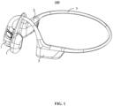
- the present disclosure provides a headphone 100, as shown in FIG. 1 , which is a general assembly diagram of the headphone 100 of the present disclosure.
- the headphone 100 includes a movement assembly 1, an ear hook 2 and a rear hook 3.
- the number of the movement assembly 1 is two, and the two movement assemblies 1 are configured to transmit vibration and/or sound to the left and right ears of a user, respectively, and the two movement assemblies 1 may be the same or different.
- one of the two movement assemblies 1 may be provided with a microphone, and the other one of the two movement assemblies 1 may not be provided with a microphone.
- one of the two movement assemblies 1 may be provided with a key and a corresponding circuit board, and the other one of the two movement assemblies 1 may not be provided with the key and the corresponding circuit board.
- Movement modules e.g., a loudspeaker module
- the number of the ear hook 2 may be two, and the two ear hooks 2 may be located in the left and right ears of the user, respectively, so as to allow the movement assemblies 1 to fit the face of the user.
- One ear hook 2 may be provided with a battery, and the other ear hook 2 may be provided with a control circuit, or the like.
- One end of the ear hook 2 is connected to the movement assembly 1, and the other end of the ear hook 2 is connected to the rear hook 3.
- the rear hook 3 connects the two ear hangers 2, and the rear hook 3 is configured to wrap around the back of the neck or the back of the brain of the user, and may provide a clamping force to make the two movement assemblies 1 clamped to both sides of the face of the user and the ear hooks 2 hang more firmly on the ears of the user.
- the headphone 100 of the embodiments of the present disclosure includes a housing 10, a sealing ring 20, a microphone assembly 30, and a positioning member 40.
- the movement assembly 1 includes the housing 10, the sealing ring 20, the microphone assembly 30, and the positioning member 40.
- the housing 10 includes a bottom wall portion 110 and a side wall portion 120 connected with the bottom wall portion 110.
- the bottom wall portion 110 and the side wall portion 120 cooperates to form an accommodation space 101, and a support surface 102 is provided on a side of the side wall portion 120 toward the accommodation space 101.
- a sound guiding hole 103 is provided on the support surface 102 for connecting the accommodation space 101 and an exterior of the housing 10.
- the sealing ring 20 is provided on the support surface 102 and surrounds the sound guiding hole 103.
- the microphone assembly 30 includes a sound guiding member 310 and a microphone 320.
- the sound guiding member 310 is configured to hold the sealing ring 20 against the support surface 102, and a sound guiding channel 301 is provided on the sound guiding member 310 for guiding a sound input from the sound guiding hole 103 to the microphone 320.
- the positioning member 40 is inserted between the housing 10 and the sound guiding member 310 to enable the sound guiding member 310 to remain the sealing ring 20 in a press-hold condition.
- the number of the sound guiding hole 103 may be one or two.
- two sound guiding holes 103 are provided side-by-side on the support surface 102.
- the number of the sound guiding hole 103 may also be three, four, five, etc.
- the sealing ring 20 By providing the sealing ring 20 surrounding the sound guiding hole 103, the sealing ring 20 is disposed between the support surface 102 and the sound guiding member 310, and the sound guiding member 310 is provided with a sound guiding channel 301 that conducts the sound input from the sound guiding hole 103 to the microphone 320 to achieve good conduction of sound, which is conducive to enhancing the quality of the transmitted sound.
- the effect of pressing the sealing ring 20 by the sound guiding member 310 is effectively improved, thereby improving the sealing effect of the sealing ring 20 to realize good sound conduction, which is conducive to improving the usage of the headphone 100.
- the first positioning portion 311 is provided on the sound guiding member 310, and the second positioning portion 130 is provided on the housing 10.
- the first positioning portion 311 is closer to the sealing ring 20 than the second positioning portion 130, and the positioning member 40 is inserted between the first positioning portion 311 and the second positioning portion 130.
- the positioning member 40 By providing the first positioning portion 311 and the second positioning portion 130, it is convenient to locate and install the positioning member 40, and the positioning member 40 is capable of continuously exerting pressure on the first positioning portion 311 under the restriction of the second positioning portion 130, thus the sound guiding member 310 remains the sealing ring 20 on the press-hold condition, which is conducive to enhancing the sealing effect of the sealing ring 20, thus improving the usage of the headphone 100.
- the positioning member 40 is provided to be capable of being inserted between the first positioning portion 311 and the second positioning portion 130 from a side of the sound guiding member 310 back away from the bottom wall portion 110.
- the sealing ring 20 may be free from an excessive pressing holding force when the positioning member 40 is not provided, to ensure the sealing ring 20 not be deformed due to the additional pressing holding force when the sealing ring 20 is provided, such as when wrinkles or gaps occur on the support surface 102, effectively improving the sealing effect of the sealing ring 20, which is conducive to reducing the difficulty of assembling the sealing ring 20 and is conducive to improving the efficiency of assembling the sealing ring 20 and effectively improving the yield rate of the headphone 100.
- the number of the second positioning portions 130 is two, the two second positioning portions 130 are disposed on two sides of the sound guiding member 310 in a vertical direction F2 perpendicular to the pressing direction F1.
- a middle region of the positioning member 40 abuts the first positioning portion 311, and two ends of the positioning member 40 abut two second positioning portions 130, respectively.
- the two second positioning portions 130 By providing two second positioning portions 130, it is easy to locate and install the positioning member 40, and the two second positioning portions 130 abut the two ends of the positioning member 40, respectively, which is conducive to realizing the balance of force on the two sides of the positioning member 40 and is conducive to enhancing the service life and usage of the headphone 100.
- the sound guiding member 310 further includes a main body portion 312.
- the main body portion 312 is supported on the bottom wall portion 110, the first positioning portion 311 is located on a side of the main body portion 312 back away from the bottom wall portion 110.
- Two second positioning portions 130 are located on two sides of the positioning member 40, and the two ends of the positioning member 130 are bent relative to the middle of the positioning member 40.
- the two ends of the positioning member 40 By bending the two ends of the positioning member 40 relative to the middle region of the positioning member 40 to realize that the two second positioning portions 130 abut the two ends of the positioning member 40 and the middle region of the positioning member 40 abuts the first positioning portion 311, making the headphone 100 have a more compact structure inside the headphone 100, improving the integration and tightness of the structure, which is conducive to enhancing the space utilization inside the headphone 100.
- the two ends of the positioning member 40 is bent relative to the middle region of the positioning member 40, which may enhance the strength of the positioning member 40, reduce the possibility of damage to the positioning member 40, and thus enhance the service life of the headphone.
- the sound guiding member 310 further includes a catch block 313, the catch block 313 being located on the side of the main body portion 312 back away from the bottom wall portion 110 and spaced apart from the first positioning portion 311 along the pressing direction F1 to cooperate with each other to form the first catch slot 302.
- the middle region of the positioning member 40 is at least partially disposed within the first catch slot 302.
- the positioning member 40 By setting the catch block 313 to cooperate with the first positioning portion 311 to form the first catch slot 302, it is convenient for the positioning member 40 to be provided and fixed, which is conducive to reducing the difficulty of assembling the headphone 100 and is conducive to improving the assembly efficiency and the yield rate of the headphone 100.
- the width L1 of the catch block 313 is smaller than the width L2 of the main body portion 312.
- the middle region of the positioning member 40 is provided with a second catch slot 402, and the catch block 313 is provided in the second catch slot 402.
- the width L1 of the catch block 313 By setting the width L1 of the catch block 313 to be smaller than the width L2 of the main body portion 312 in the vertical direction F2 and setting the second catch slot 402 in the middle region of the positioning member 40, it is easy to locate and install the positioning member 40, which is conducive to lowering the assembly difficulty of the headphone 100, and improving the assembly efficiency and yield rate. Additionally, the first catch slot 302 and the second catch slot 402 are provided simultaneously to enable double positioning of the assembly of the positioning member 40, which effectively improves the positioning effect and enhances the accuracy of the assembly.
- the microphone 320 is provided on the side of the main body portion 312 toward the bottom wall portion 110, the side of the first positioning portion 311 toward the support surface 102 press the sealing ring 20, and the sound guiding channel 301 extends to the main body portion 312 via the first positioning portion 311 and the catch block 313.
- the sound may be transmitted from the sound guiding channel 301 to the microphone 320, effectively guaranteeing the sound transmission effect and making the internal structure of the headphone 100 more compact, improving the integration and tightness of the structure, which is conducive to improving the space utilization rate inside the headphone 100.
- the microphone assembly 30 further includes a lead wire 330 connected to the microphone 320, and the side of the main body portion 312 facing the bottom wall portion 110 is further provided with a lead slot 303.
- the lead wire 330 is provided within the lead slot 303.
- the lead slot 303 By providing the lead slot 303 to accommodate the lead wire 330, it is convenient to protect the lead wire 330, reduce the possibility that the lead wire 330 receives interference, and make the structure inside the headphone 100 more compact and improve the integration and tightness of the structure, which is conducive to improving the space utilization rate inside the headphone 100.
- the housing 10 further includes a guide portion 140 disposed on the bottom wall portion 110, and the guide portion 140 is configured to guide the sound guiding member 310 along the pressing direction F1.
- the guide portion 140 is provided such that the sound guiding member 310 tends to move toward the support surface 102 and the bottom wall portion 110 simultaneously or move away from the support surface 102 and the bottom wall portion 110 simultaneously.
- Such a setting facilitates the positioning and installation of the sound guiding member 310, which is conducive to reducing the difficulty of assembling the sound guiding member 310, and further improves the pressing effect of the sound guiding member 310 on the sealing ring 20, which in turn improves the sealing effect of the sealing ring 20.
- the microphone assembly 30 further includes a lead wire 330 connected to the microphone 320.
- One end of the lead wire 330 close to the microphone 320 is suspended relative to the bottom wall portion 110.
- the housing 10 further includes a wire-bearing portion 150 disposed on the bottom wall portion 110. The wire-bearing portion 150 is configured to support the lead wire 330 and guide the lead wire 330 toward the bottom wall portion 110.
- the wire-bearing portion 150 By providing the wire-bearing portion 150 to support the lead wire 330 and guide the lead wire 330 toward the bottom wall portion 110, it is conducive to reducing the probability of the lead wire 330 being subjected to external interference, such as shaking, etc., and is conducive to enhancing the stability and reliability of the operation of the lead wire 330.
- the headphone 100 of the embodiments of the present disclosure includes the housing 10, the sealing ring 20, and the microphone assembly 30.
- the movement assembly 1 includes the housing 10, the sealing ring 20, and the microphone assembly 30.
- the housing 10 includes a bottom wall portion 110, a side wall portion 120 connected with the bottom wall portion 110, and a positioning portion 160.
- the bottom wall portion 110 and the side wall portion 120 cooperates to form an accommodation space 101
- the side wall portion 120 is provided with a support surface 102 on a side facing the accommodation space 101
- the support surface 102 is provided with a sound guiding hole 103 for connecting the accommodation space 101 and the exterior of the housing 10
- the positioning portion 160 is provided on the bottom wall portion 110 and/or the side wall portion 120.
- the sealing ring 20 is provided on the support surface 102 and encircles the sound guiding hole 103.
- the microphone assembly 30 includes a sound guiding member 310 and a microphone 320.
- the sound guiding member 310 is configured to hold the sealing ring 20 against the support surface 102, and a sound guiding channel 301 is provided on the sound guiding member 310 for guiding the sound input from the sound guiding hole 103 to the microphone 320.
- the positioning portion 160 abuts the sound guiding member 310 to allow the sound guiding member 310 to remain pressed against the sealing ring 20.
- the number of the sound guiding hole 103 may be, for example, one, or two.
- two sound guiding holes 103 are provided side-by-side on the support surface 102, and certainly the number of the sound guiding hole 103 may also be three, four, five, etc.
- the sealing ring 20 By providing the sealing ring 20 encircling the sound guiding hole 103, the sealing ring 20 is located between the support surface 102 and the sound guiding member 310, and the sound guiding member 310 is provided with a sound guiding channel 301 that conducts the sound input from the sound guiding hole 103 to the microphone 320 to achieve good conduction of sound, which is conducive to enhancing the quality of the transmitted sound.
- the sound guiding member 310 remains the sealing ring 20 in a press-hold condition. The sealing effect of the sealing ring 20 is effectively improved, and the assembly difficulty is reduced, which is conducive to improving the assembly efficiency and the yield rate.
- the positioning portion 160 is integrally molded with the bottom wall portion 110 and/or the side wall portion 120.
- the accurate setting of the positioning portion 160 may be realized and the effect of the positioning portion 160 against the sound guiding member 310 may be improved, thus improving the usage of the headphone 100.
- the sound guiding member 310 in the pressing direction F1 of the sound guiding member 310 against the sealing ring 20, the sound guiding member 310 has a first end face 304 facing the support surface 102, and a second end face 305 opposite to the first end face 304.
- the first end face 304 abuts the sealing ring 20, and the positioning portion 160 abuts the second end face 305.
- the positioning portion 160 By providing the first end surface 304 and the second end surface 305 that respectively abuts the sealing ring 20 and the positioning portion 160, it is possible to realize that the positioning portion 160 abuts the sound guiding member 310, which in turn abuts the sealing ring 20. With a simple and effective, it is conducive to improving the integration and tightness of the structure and is conducive to improving the space utilization of the headphone 100.
- the sound guiding member 310 is configured to be capable of being inserted and positioned between the support surface 102 and the positioning portion 160 under the action of the pressing force toward the bottom wall portion 110.
- Such a setting is capable of simplifying the assembly steps and reducing the difficulty of assembly while realizing the pressing force of the sound guiding member 310 on the sealing ring 20, thereby enhancing the assembly efficiency.
- the side of the positioning portion 160 facing the support surface 102 has an abutting surface 105 and a guiding surface connected with the abutting surface.
- the guiding surface is configured to guide an end of the sound guiding member 310 back away from the support surface 102 to move to the abutting surface 105 when the sound guiding member 310 is subjected to pressing pressure, thereby causing the abutting surface 105 to abut the second end surface 305.
- the assembly process of the sound guiding member 310 is clear and smooth. While ensuring the sealing effect of the sealing ring 20, it is conducive to reducing the difficulty of assembling the headphone 100 and improving the assembly efficiency of the headphone 100.
- the microphone 320 is provided on the side of the sound guiding member 310 facing the bottom wall portion 110.
- the microphone assembly 30 further includes a lead wire 330 connected to the microphone 320.
- the side of the sound guiding member 310 facing the bottom wall portion 110 is further provided with a lead slot 303, and the lead wire 330 is provided within the lead slot 303.
- the lead slot 303 By providing the lead slot 303 to accommodate the lead wire 330, it is convenient to protect the lead wire 330, reduce the possibility of the lead wire 330 being interfered with, and make the structure inside the headphone 100 more compact, which improves the integration and tightness of the structure and is conducive to improving the space utilization rate inside the headphone 100.
- the sound guiding member 310 includes two support portions 314 spaced apart along the vertical direction F2 perpendicular to the pressing direction F1 and supported on the bottom wall portion 110.
- the lead slot 303 is disposed between the two support portions 314.
- the positioning portion 160 is configured to abut a second end surface 305 of at least one of two support portions 314 and make the lead slot 303 remain at least exposed on the side of the sound guiding member 310 back from the support surface 102.
- the support portion 314 By providing the support portion 314 to make the positioning portion 160 abut the sound guiding member 310 and the lead slot 303 is located between the two support portions 314, the effect of the sound guiding member 310 pressing on the sealing ring 20 is ensured, and at the same time, the structural integration and tightness is improved, which is conducive to enhancing the utilization of space inside the headphone 100.
- one of the two support portions 314 is provided adjacent to the side wall portion 120, and the positioning portion 160 is provided on the side wall portion 120.
- the positioning portion 160 is provided on the side wall portion 120.
- the housing 10 further includes a guide portion 140 disposed on the bottom wall portion 110, and the guide portion 140 is configured to guide the sound guiding member 310 in the pressing direction F1.
- the microphone assembly 30 further includes the lead wire 330 connected to the microphone 320, the end of the lead wire 330 close to the microphone 320 is suspended relative to the bottom wall portion 110.
- the housing 10 further includes a wire-bearing portion 150 disposed on the bottom wall portion 110, the wire-bearing portion 150 is configured to support the lead wire 330 and guide the lead wire 330 toward the bottom wall portion 110.
- the wire-bearing portion 150 By providing the wire-bearing portion 150 to support the lead wire 330 and guide the lead wire 330 toward the bottom wall portion 110, it is conducive to reducing the probability of the lead wire 330 being subjected to external interference, such as shaking, etc., and is conducive to enhancing the stability and reliability of the operation of the lead wire 330.
Landscapes
- Engineering & Computer Science (AREA)
- Physics & Mathematics (AREA)
- Acoustics & Sound (AREA)
- Signal Processing (AREA)
- Manufacturing & Machinery (AREA)
- Headphones And Earphones (AREA)
Abstract
Description
- The present disclosure relates to the technical field of electronic devices, and in particular, to headphones.
- With the increasing popularity of electronic devices, electronic devices have become an indispensable social and entertainment tool in people's daily lives, and people's requirements for electronic devices are getting higher and higher. Electronic devices such as headphones and smart glasses have also been widely used in people's daily lives. They can be used with terminal devices such as mobile phones and computers to provide users with an auditory feast.
- The present disclosure provides a headphone. The headphone may include a housing, a sealing ring, a microphone assembly, and a positioning member. The housing may include a bottom wall portion and a side wall portion connected with the bottom wall portion. The bottom wall portion and the side wall portion may cooperate to form an accommodation space. A support surface may be provided on a side of the side wall portion facing the accommodation space, and a sound guiding hole may be provided on the support surface for connecting the accommodation space and an exterior of the housing. The sealing ring may be provided on the support surface and encircling the sound guiding hole. The microphone assembly may include a sound guiding member and a microphone. The sound guiding member may be configured to hold the sealing ring against the support surface, and a sound guiding channel may be provided on the sound guiding member for guiding a sound input from the sound guiding hole to the microphone. The positioning member may be inserted between the housing and the sound guiding member to enable the sound guiding member to remain the sealing ring in a press-hold condition.
- In some embodiments, one or more first positioning portions may be provided on the sound guiding member, and one or more second positioning portions may be provided on the housing. The one or more first positioning portions may be closer to the sealing ring than the one or more second positioning portions in a pressing direction of the sound guiding member against the sealing ring. The positioning member may be inserted between the one or more first positioning portions and the one or more second positioning portions.
- In some embodiments, the positioning member may be capable of being inserted between the one or more first positioning portions and the one or more second positioning portions from a side of the sound guiding member back away from the bottom wall portion.
- In some embodiments, a count of the one or more second positioning portions may be two. The two second positioning portions may be provided on two sides of the sound guiding member in a vertical direction perpendicular to the pressing direction. A middle region of the positioning member may abut the one or more first positioning portions, and two ends of the positioning member may abut the two second positioning portions, respectively.
- In some embodiments, the sound guiding member may further include a main body portion. The main body portion may be supported on the bottom wall portion. The one or more first positioning portions may be located on a side of the main body portion back away from the bottom wall portion. The two second positioning portions may be located on two sides of the main body portion. The two ends of the positioning member may be bent relative to the middle region of the positioning member.
- In some embodiments, the sound guiding member may further include a catch block. The catch block may be located on the side of the main body portion back away from the bottom wall portion and spaced apart from the one or more first positioning portions along the pressing direction to cooperate with each other to form a first catch slot. The middle region of the positioning member may be at least partially disposed within the first catch slot.
- In some embodiments, in the vertical direction, a width of the catch block may be smaller than a width of the main body portion, a second catch slot may be provided in the middle region of the positioning member, and the catch block may be provided in the second catch slot.
- In some embodiments, the microphone may be provided on a side of the main body portion facing the bottom wall portion, a side of the one or more first positioning portions may face the support surface presses the sealing ring, and the sound guiding channel may extend to the main body portion via the one or more first positioning portions and the catch block.
- In some embodiments, the microphone assembly further may include a lead wire connected to the microphone, the side of the main body portion may face the bottom wall portion is further provided with a lead slot, and the lead wire may be provided within the lead slot.
- In some embodiments, the housing may further include a guide portion disposed on the bottom wall portion, and the guide portion may be configured to guide the sound guiding member in the pressing direction.
- In some embodiments, the guide portion may be provided such that the sound guiding member tends to move toward the support surface and the bottom wall portion simultaneously or move away from the support surface and the bottom wall portion simultaneously.
- In some embodiments, the microphone assembly may further include a lead wire connected to the microphone. One end of the lead wire close to the microphone may be suspended relative to the bottom wall portion. The housing may further include a wire-bearing portion disposed on the bottom wall portion. The wire-bearing portion may be configured to support the lead wire and guide the lead wire toward the bottom wall portion.
- In some embodiments, the housing may include one or more positioning portions. The one or more positioning portions may be provided on the bottom wall portion and/or the side wall portion, and the one or more positioning portions may abut the sound guiding member to allow the sound guiding member to remain the sealing ring in a press-hold condition.
- In some embodiments, the one or more positioning portions may be integrally molded with the bottom wall portion and/or the side wall portion.
- In some embodiments, in a pressing direction of the sound guiding member against the sealing ring, the sound guiding member may have a first end face facing the support surface and a second end face opposite to the first end face. The first end face may abut the sealing ring, and the one or more positioning portions may abut the second end face.
- In some embodiments, the sound guiding member may be configured to be capable of being inserted and positioned between the support surface and the one or more positioning portions under an action of a pressing force toward the bottom wall portion.
- In some embodiments, a side of the one or more positioning portions toward the support surface may have an abutting surface and a guiding surface connected with the abutting surface. The guiding surface may be configured to guide an end of the sound guiding member back away from the support surface to move to the abutting surface when the sound guiding member is subjected to the pressing force, which in turn causes the abutting surface to abut the second end face.
- In some embodiments, the microphone may be provided on a side of the sound guiding member toward the bottom wall portion. The microphone assembly may further include a lead wire connected to the microphone. A lead slot may be further provided on the side of the sound guiding member toward the bottom wall portion. The lead wire may be provided in the lead slot.
- In some embodiments, the sound guiding member may include two support portions spaced apart in a vertical direction perpendicular to the pressing direction and supported on the bottom wall portion. The lead slot may be disposed between the two support portions. The one or more positioning portions may be configured to abut a second end face of at least one of the two support portions and make the lead slot remain at least exposed on a side of the sound guiding member back from the support surface.
- In some embodiments, one of the two support portions may be provided adjacent to the side wall portion, and the one or more positioning portions may be provided on the side wall portion.
- In some embodiments, the housing may further include a guide portion disposed on the bottom wall portion, and the guide portion may be configured to guide the sound guiding member in the pressing direction.
- In some embodiments, the microphone assembly may further include a lead wire connected to the microphone. One end of the lead wire close to the microphone may be suspended relative to the bottom wall portion. The housing may further include a wire-bearing portion disposed on the bottom wall portion. The wire-bearing portion may be configured to support the lead wire and guide the lead wire toward the bottom wall portion.
- To more clearly illustrate the technical solutions related to the embodiments of the present disclosure, a brief introduction of the drawings referred to the description of the embodiments is provided below. Obviously, the drawings described below are only some examples or embodiments of the present disclosure. Those having ordinary skills in the art, without further creative efforts, may apply the present disclosure to other similar scenarios according to these drawings.
-
FIG. 1 is a schematic diagram illustrating a three-dimensional structure of a headphone according to some embodiments of the present disclosure; -
FIG. 2 is a schematic diagram illustrating a part of the structure of the headphone shown inFIG. 1 ; -
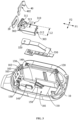
FIG. 3 is a schematic diagram illustrating a disassembled structure of the part of the structure of the headphone shown inFIG. 2 ; -
FIG. 4 is a schematic diagram illustrating a three-dimensional structure of a sound guiding member shown inFIG. 3 ; -
FIG. 5 is a sectional structure of the headphone shown inFIG. 2 along a P-P sectional direction; -
FIG. 6 is a schematic diagram illustrating another disassembled structure of the part of the structure of the headphone shown inFIG. 2 ; -
FIG. 7 is a schematic diagram illustrating another part of the structure of the headphone shown inFIG. 1 ; -
FIG. 8 is a schematic diagram illustrating a disassembled structure of the part of the structure of the headphone shown inFIG. 6 ; and -
FIG. 9 is a sectional structure of the headphone shown inFIG. 6 along a G-G sectional direction. - The technical solutions in the embodiments of the present disclosure will be clearly and completely described below in conjunction with the accompanying drawings in the embodiments of the present disclosure. It is clear that the described embodiments are only a part of the embodiments of the present disclosure, and not all of the embodiments. Based on the embodiments in the present disclosure, all other embodiments obtained by a person of ordinary skill in the art without making creative labor fall within the scope of protection of the present disclosure.
- References to "embodiments" in the present disclosure mean that particular features, structures, or characteristics described in conjunction with embodiments may be included in at least one embodiment of the present disclosure. It is understood by those of skill in the art, both explicitly and implicitly, that the embodiments described in the present disclosure may be combined with other embodiments.
- The present disclosure provides a
headphone 100, as shown inFIG. 1 , which is a general assembly diagram of theheadphone 100 of the present disclosure. Theheadphone 100 includes amovement assembly 1, anear hook 2 and arear hook 3. In this embodiment, the number of themovement assembly 1 is two, and the twomovement assemblies 1 are configured to transmit vibration and/or sound to the left and right ears of a user, respectively, and the twomovement assemblies 1 may be the same or different. For example, one of the twomovement assemblies 1 may be provided with a microphone, and the other one of the twomovement assemblies 1 may not be provided with a microphone. For example, one of the twomovement assemblies 1 may be provided with a key and a corresponding circuit board, and the other one of the twomovement assemblies 1 may not be provided with the key and the corresponding circuit board. Movement modules (e.g., a loudspeaker module) of the twomovement assemblies 1 may be identical. The number of theear hook 2 may be two, and the twoear hooks 2 may be located in the left and right ears of the user, respectively, so as to allow themovement assemblies 1 to fit the face of the user. Oneear hook 2 may be provided with a battery, and theother ear hook 2 may be provided with a control circuit, or the like. One end of theear hook 2 is connected to themovement assembly 1, and the other end of theear hook 2 is connected to therear hook 3. Therear hook 3 connects the twoear hangers 2, and therear hook 3 is configured to wrap around the back of the neck or the back of the brain of the user, and may provide a clamping force to make the twomovement assemblies 1 clamped to both sides of the face of the user and the ear hooks 2 hang more firmly on the ears of the user. - In some embodiments, as shown in
FIG. 2 , theheadphone 100 of the embodiments of the present disclosure includes ahousing 10, a sealingring 20, amicrophone assembly 30, and a positioningmember 40. Optionally, themovement assembly 1 includes thehousing 10, the sealingring 20, themicrophone assembly 30, and the positioningmember 40. - Optionally, as shown in
FIG. 2 to FIG. 5 , thehousing 10 includes abottom wall portion 110 and aside wall portion 120 connected with thebottom wall portion 110. Thebottom wall portion 110 and theside wall portion 120 cooperates to form anaccommodation space 101, and asupport surface 102 is provided on a side of theside wall portion 120 toward theaccommodation space 101. Asound guiding hole 103 is provided on thesupport surface 102 for connecting theaccommodation space 101 and an exterior of thehousing 10. The sealingring 20 is provided on thesupport surface 102 and surrounds thesound guiding hole 103. Themicrophone assembly 30 includes asound guiding member 310 and amicrophone 320. Thesound guiding member 310 is configured to hold the sealingring 20 against thesupport surface 102, and asound guiding channel 301 is provided on thesound guiding member 310 for guiding a sound input from thesound guiding hole 103 to themicrophone 320. The positioningmember 40 is inserted between thehousing 10 and thesound guiding member 310 to enable thesound guiding member 310 to remain the sealingring 20 in a press-hold condition. The number of thesound guiding hole 103 may be one or two. For example, twosound guiding holes 103 are provided side-by-side on thesupport surface 102. Certainly, the number of thesound guiding hole 103 may also be three, four, five, etc. - By providing the sealing
ring 20 surrounding thesound guiding hole 103, the sealingring 20 is disposed between thesupport surface 102 and thesound guiding member 310, and thesound guiding member 310 is provided with asound guiding channel 301 that conducts the sound input from thesound guiding hole 103 to themicrophone 320 to achieve good conduction of sound, which is conducive to enhancing the quality of the transmitted sound. In addition, by setting thepositioning member 40 and inserting it between thehousing 10 and thesound guiding member 310 to remain the sealingring 20 in a press-hold condition, the effect of pressing the sealingring 20 by thesound guiding member 310 is effectively improved, thereby improving the sealing effect of the sealingring 20 to realize good sound conduction, which is conducive to improving the usage of theheadphone 100. - Optionally, as shown in
FIG. 3 , thefirst positioning portion 311 is provided on thesound guiding member 310, and thesecond positioning portion 130 is provided on thehousing 10. In the pressing direction F1 of thesound guiding member 310 against the sealingring 20, thefirst positioning portion 311 is closer to the sealingring 20 than thesecond positioning portion 130, and the positioningmember 40 is inserted between thefirst positioning portion 311 and thesecond positioning portion 130. - By providing the
first positioning portion 311 and thesecond positioning portion 130, it is convenient to locate and install the positioningmember 40, and the positioningmember 40 is capable of continuously exerting pressure on thefirst positioning portion 311 under the restriction of thesecond positioning portion 130, thus thesound guiding member 310 remains the sealingring 20 on the press-hold condition, which is conducive to enhancing the sealing effect of the sealingring 20, thus improving the usage of theheadphone 100. - Optionally, as shown in
FIG. 2 andFIG. 3 , the positioningmember 40 is provided to be capable of being inserted between thefirst positioning portion 311 and thesecond positioning portion 130 from a side of thesound guiding member 310 back away from thebottom wall portion 110. - By setting the
positioning member 40 to be inserted between thefirst locating portion 311 and thesecond locating portion 130 from the side of thesound guiding member 310 back away from thebottom wall portion 110, the sealingring 20 may be free from an excessive pressing holding force when the positioningmember 40 is not provided, to ensure the sealingring 20 not be deformed due to the additional pressing holding force when the sealingring 20 is provided, such as when wrinkles or gaps occur on thesupport surface 102, effectively improving the sealing effect of the sealingring 20, which is conducive to reducing the difficulty of assembling the sealingring 20 and is conducive to improving the efficiency of assembling the sealingring 20 and effectively improving the yield rate of theheadphone 100. - Optionally, as shown in
FIG. 3 , the number of thesecond positioning portions 130 is two, the twosecond positioning portions 130 are disposed on two sides of thesound guiding member 310 in a vertical direction F2 perpendicular to the pressing direction F1. A middle region of the positioningmember 40 abuts thefirst positioning portion 311, and two ends of the positioningmember 40 abut twosecond positioning portions 130, respectively. - By providing two
second positioning portions 130, it is easy to locate and install the positioningmember 40, and the twosecond positioning portions 130 abut the two ends of the positioningmember 40, respectively, which is conducive to realizing the balance of force on the two sides of the positioningmember 40 and is conducive to enhancing the service life and usage of theheadphone 100. - Optionally, as shown in
FIG. 3 andFIG. 4 , thesound guiding member 310 further includes amain body portion 312. Themain body portion 312 is supported on thebottom wall portion 110, thefirst positioning portion 311 is located on a side of themain body portion 312 back away from thebottom wall portion 110. Twosecond positioning portions 130 are located on two sides of the positioningmember 40, and the two ends of thepositioning member 130 are bent relative to the middle of the positioningmember 40. - By bending the two ends of the positioning
member 40 relative to the middle region of the positioningmember 40 to realize that the twosecond positioning portions 130 abut the two ends of the positioningmember 40 and the middle region of the positioningmember 40 abuts thefirst positioning portion 311, making theheadphone 100 have a more compact structure inside theheadphone 100, improving the integration and tightness of the structure, which is conducive to enhancing the space utilization inside theheadphone 100. In addition, the two ends of the positioningmember 40 is bent relative to the middle region of the positioningmember 40, which may enhance the strength of the positioningmember 40, reduce the possibility of damage to the positioningmember 40, and thus enhance the service life of the headphone. - Optionally, as shown in
FIG. 3 andFIG. 4 , thesound guiding member 310 further includes acatch block 313, the catch block 313 being located on the side of themain body portion 312 back away from thebottom wall portion 110 and spaced apart from thefirst positioning portion 311 along the pressing direction F1 to cooperate with each other to form thefirst catch slot 302. The middle region of the positioningmember 40 is at least partially disposed within thefirst catch slot 302. - By setting the catch block 313 to cooperate with the
first positioning portion 311 to form thefirst catch slot 302, it is convenient for the positioningmember 40 to be provided and fixed, which is conducive to reducing the difficulty of assembling theheadphone 100 and is conducive to improving the assembly efficiency and the yield rate of theheadphone 100. - Optionally, as shown in
FIG. 3 , in the vertical direction F2, the width L1 of thecatch block 313 is smaller than the width L2 of themain body portion 312. The middle region of the positioningmember 40 is provided with asecond catch slot 402, and thecatch block 313 is provided in thesecond catch slot 402. - By setting the width L1 of the catch block 313 to be smaller than the width L2 of the
main body portion 312 in the vertical direction F2 and setting thesecond catch slot 402 in the middle region of the positioningmember 40, it is easy to locate and install the positioningmember 40, which is conducive to lowering the assembly difficulty of theheadphone 100, and improving the assembly efficiency and yield rate. Additionally, thefirst catch slot 302 and thesecond catch slot 402 are provided simultaneously to enable double positioning of the assembly of the positioningmember 40, which effectively improves the positioning effect and enhances the accuracy of the assembly. - Optionally, as shown in
FIG. 3 andFIG. 5 , themicrophone 320 is provided on the side of themain body portion 312 toward thebottom wall portion 110, the side of thefirst positioning portion 311 toward thesupport surface 102 press the sealingring 20, and thesound guiding channel 301 extends to themain body portion 312 via thefirst positioning portion 311 and thecatch block 313. In this way, the sound may be transmitted from thesound guiding channel 301 to themicrophone 320, effectively guaranteeing the sound transmission effect and making the internal structure of theheadphone 100 more compact, improving the integration and tightness of the structure, which is conducive to improving the space utilization rate inside theheadphone 100. - Optionally, as shown in
FIG. 3 , themicrophone assembly 30 further includes alead wire 330 connected to themicrophone 320, and the side of themain body portion 312 facing thebottom wall portion 110 is further provided with alead slot 303. Thelead wire 330 is provided within thelead slot 303. - By providing the
lead slot 303 to accommodate thelead wire 330, it is convenient to protect thelead wire 330, reduce the possibility that thelead wire 330 receives interference, and make the structure inside theheadphone 100 more compact and improve the integration and tightness of the structure, which is conducive to improving the space utilization rate inside theheadphone 100. - Optionally, as shown in
FIG. 3 , thehousing 10 further includes aguide portion 140 disposed on thebottom wall portion 110, and theguide portion 140 is configured to guide thesound guiding member 310 along the pressing direction F1. - By providing the
guide portion 140 on thebottom wall portion 110, it is easy to position and install thesound guiding member 310, reduce the difficulty of assembling thesound guiding member 310, and effectively guarantee that thesound guiding member 310 presses the sealingring 20 along the pressing direction F1, thereby improving the sealing effect of the sealingring 20. - Optionally, as shown in
FIG. 6 , theguide portion 140 is provided such that thesound guiding member 310 tends to move toward thesupport surface 102 and thebottom wall portion 110 simultaneously or move away from thesupport surface 102 and thebottom wall portion 110 simultaneously. Such a setting facilitates the positioning and installation of thesound guiding member 310, which is conducive to reducing the difficulty of assembling thesound guiding member 310, and further improves the pressing effect of thesound guiding member 310 on the sealingring 20, which in turn improves the sealing effect of the sealingring 20. - Optionally, as shown in
FIG. 3 andFIG. 5 , themicrophone assembly 30 further includes alead wire 330 connected to themicrophone 320. One end of thelead wire 330 close to themicrophone 320 is suspended relative to thebottom wall portion 110. Thehousing 10 further includes a wire-bearingportion 150 disposed on thebottom wall portion 110. The wire-bearingportion 150 is configured to support thelead wire 330 and guide thelead wire 330 toward thebottom wall portion 110. - By providing the wire-bearing
portion 150 to support thelead wire 330 and guide thelead wire 330 toward thebottom wall portion 110, it is conducive to reducing the probability of thelead wire 330 being subjected to external interference, such as shaking, etc., and is conducive to enhancing the stability and reliability of the operation of thelead wire 330. - In some embodiments, as shown in
FIG. 7 , theheadphone 100 of the embodiments of the present disclosure includes thehousing 10, the sealingring 20, and themicrophone assembly 30. Optionally, themovement assembly 1 includes thehousing 10, the sealingring 20, and themicrophone assembly 30. - Optionally, as shown in
FIG. 7 to FIG. 9 , thehousing 10 includes abottom wall portion 110, aside wall portion 120 connected with thebottom wall portion 110, and apositioning portion 160. Thebottom wall portion 110 and theside wall portion 120 cooperates to form anaccommodation space 101, theside wall portion 120 is provided with asupport surface 102 on a side facing theaccommodation space 101, thesupport surface 102 is provided with asound guiding hole 103 for connecting theaccommodation space 101 and the exterior of thehousing 10, and thepositioning portion 160 is provided on thebottom wall portion 110 and/or theside wall portion 120. The sealingring 20 is provided on thesupport surface 102 and encircles thesound guiding hole 103. Themicrophone assembly 30 includes asound guiding member 310 and amicrophone 320. Thesound guiding member 310 is configured to hold the sealingring 20 against thesupport surface 102, and asound guiding channel 301 is provided on thesound guiding member 310 for guiding the sound input from thesound guiding hole 103 to themicrophone 320. Thepositioning portion 160 abuts thesound guiding member 310 to allow thesound guiding member 310 to remain pressed against the sealingring 20. The number of thesound guiding hole 103 may be, for example, one, or two. For example, twosound guiding holes 103 are provided side-by-side on thesupport surface 102, and certainly the number of thesound guiding hole 103 may also be three, four, five, etc. - By providing the sealing
ring 20 encircling thesound guiding hole 103, the sealingring 20 is located between thesupport surface 102 and thesound guiding member 310, and thesound guiding member 310 is provided with asound guiding channel 301 that conducts the sound input from thesound guiding hole 103 to themicrophone 320 to achieve good conduction of sound, which is conducive to enhancing the quality of the transmitted sound. In addition, by providing thepositioning portion 160 to abut thesound guiding member 310, thesound guiding member 310 remains the sealingring 20 in a press-hold condition. The sealing effect of the sealingring 20 is effectively improved, and the assembly difficulty is reduced, which is conducive to improving the assembly efficiency and the yield rate. - Optionally, the
positioning portion 160 is integrally molded with thebottom wall portion 110 and/or theside wall portion 120. By integrally molding thepositioning portion 160, the accurate setting of thepositioning portion 160 may be realized and the effect of thepositioning portion 160 against thesound guiding member 310 may be improved, thus improving the usage of theheadphone 100. - Optionally, as shown in
FIG. 8 , in the pressing direction F1 of thesound guiding member 310 against the sealingring 20, thesound guiding member 310 has afirst end face 304 facing thesupport surface 102, and asecond end face 305 opposite to thefirst end face 304. Thefirst end face 304 abuts the sealingring 20, and thepositioning portion 160 abuts thesecond end face 305. - By providing the
first end surface 304 and thesecond end surface 305 that respectively abuts the sealingring 20 and thepositioning portion 160, it is possible to realize that thepositioning portion 160 abuts thesound guiding member 310, which in turn abuts the sealingring 20. With a simple and effective, it is conducive to improving the integration and tightness of the structure and is conducive to improving the space utilization of theheadphone 100. - Optionally, as shown in
FIG. 7 andFIG. 8 , thesound guiding member 310 is configured to be capable of being inserted and positioned between thesupport surface 102 and thepositioning portion 160 under the action of the pressing force toward thebottom wall portion 110. Such a setting is capable of simplifying the assembly steps and reducing the difficulty of assembly while realizing the pressing force of thesound guiding member 310 on the sealingring 20, thereby enhancing the assembly efficiency. - Optionally, as shown in
FIG. 8 andFIG. 9 , the side of thepositioning portion 160 facing thesupport surface 102 has anabutting surface 105 and a guiding surface connected with the abutting surface. The guiding surface is configured to guide an end of thesound guiding member 310 back away from thesupport surface 102 to move to theabutting surface 105 when thesound guiding member 310 is subjected to pressing pressure, thereby causing theabutting surface 105 to abut thesecond end surface 305. - By setting the
abutting surface 105 and the guidingsurface 106 connected to each other to realize that the guidingsurface 106 guides thesound guiding member 310 to be positioned and mounted, and theabutting surface 105 in turn abuts against thesecond end surface 305 to realize that thesound guiding member 310 abuts the sealingring 20, the assembly process of thesound guiding member 310 is clear and smooth. While ensuring the sealing effect of the sealingring 20, it is conducive to reducing the difficulty of assembling theheadphone 100 and improving the assembly efficiency of theheadphone 100. - Optionally, as shown in
FIG. 8 andFIG. 9 , themicrophone 320 is provided on the side of thesound guiding member 310 facing thebottom wall portion 110. Themicrophone assembly 30 further includes alead wire 330 connected to themicrophone 320. The side of thesound guiding member 310 facing thebottom wall portion 110 is further provided with alead slot 303, and thelead wire 330 is provided within thelead slot 303. - By providing the
lead slot 303 to accommodate thelead wire 330, it is convenient to protect thelead wire 330, reduce the possibility of thelead wire 330 being interfered with, and make the structure inside theheadphone 100 more compact, which improves the integration and tightness of the structure and is conducive to improving the space utilization rate inside theheadphone 100. - Optionally, as shown in
FIG. 8 , thesound guiding member 310 includes twosupport portions 314 spaced apart along the vertical direction F2 perpendicular to the pressing direction F1 and supported on thebottom wall portion 110. Thelead slot 303 is disposed between the twosupport portions 314. Thepositioning portion 160 is configured to abut asecond end surface 305 of at least one of twosupport portions 314 and make thelead slot 303 remain at least exposed on the side of thesound guiding member 310 back from thesupport surface 102. - By providing the
support portion 314 to make thepositioning portion 160 abut thesound guiding member 310 and thelead slot 303 is located between the twosupport portions 314, the effect of thesound guiding member 310 pressing on the sealingring 20 is ensured, and at the same time, the structural integration and tightness is improved, which is conducive to enhancing the utilization of space inside theheadphone 100. - Optionally, as shown in
FIG. 7 andFIG. 8 , one of the twosupport portions 314 is provided adjacent to theside wall portion 120, and thepositioning portion 160 is provided on theside wall portion 120. Set up in such a manner, it is possible to make thepositioning portion 160 to abut thesupport portion 314, and thus to make thepositioning portion 160 abut thesound guiding member 310. The structure is simple and effective, and it is conducive to enhancing the integrality and tightness of the structure, which is conducive to enhancing the utilization of space inside theheadphone 100. - Optionally, as shown in
FIG. 8 , thehousing 10 further includes aguide portion 140 disposed on thebottom wall portion 110, and theguide portion 140 is configured to guide thesound guiding member 310 in the pressing direction F1. - By providing the
guide portion 140 on thebottom wall portion 110, it is easy to position and install thesound guiding member 310, reduce the difficulty of assembling thesound guiding member 310, and effectively ensure that thesound guiding member 310 presses the sealing ring along the pressing direction F1, thus improving the sealing effect of the sealing ring. - Optionally, as shown in
FIG. 8 andFIG. 9 , themicrophone assembly 30 further includes thelead wire 330 connected to themicrophone 320, the end of thelead wire 330 close to themicrophone 320 is suspended relative to thebottom wall portion 110. Thehousing 10 further includes a wire-bearingportion 150 disposed on thebottom wall portion 110, the wire-bearingportion 150 is configured to support thelead wire 330 and guide thelead wire 330 toward thebottom wall portion 110. - By providing the wire-bearing
portion 150 to support thelead wire 330 and guide thelead wire 330 toward thebottom wall portion 110, it is conducive to reducing the probability of thelead wire 330 being subjected to external interference, such as shaking, etc., and is conducive to enhancing the stability and reliability of the operation of thelead wire 330. - The foregoing is only an example of the embodiments of the present disclosure, and is not intended to limit the scope of the patent of the present disclosure. Any equivalent structure or equivalent process transformations utilizing the contents of the present disclosure and the accompanying drawings, or applying them directly or indirectly in other related fields of technology, are all the equivalent structure or equivalent process transformations utilizing the contents of the present disclosure and the accompanying drawings, or directly or indirectly applied in other related technical fields, are included in the scope of patent protection of the present disclosure.
Claims (22)
- A headphone, comprising:a housing including a bottom wall portion and a side wall portion connected with the bottom wall portion, wherein the bottom wall portion and the side wall portion cooperate to form an accommodation space, a support surface is provided on a side of the side wall portion facing the accommodation space, and a sound guiding hole is provided on the support surface for connecting the accommodation space and an exterior of the housing;a sealing ring provided on the support surface and encircling the sound guiding hole;a microphone assembly, wherein the microphone assembly includes a sound guiding member and a microphone, the sound guiding member is configured to hold the sealing ring against the support surface, and a sound guiding channel is provided on the sound guiding member for guiding a sound input from the sound guiding hole to the microphone; anda positioning member, wherein the positioning member is inserted between the housing and the sound guiding member to enable the sound guiding member to remain the sealing ring in a press-hold condition.
- The headphone of claim 1, whereinone or more first positioning portions are provided on the sound guiding member,one or more second positioning portions are provided on the housing,the one or more first positioning portions are closer to the sealing ring than the one or more second positioning portions in a pressing direction of the sound guiding member against the sealing ring, andthe positioning member is inserted between the one or more first positioning portions and the one or more second positioning portions.
- The headphone of claim 2, wherein
the positioning member is capable of being inserted between the one or more first positioning portions and the one or more second positioning portions from a side of the sound guiding member back away from the bottom wall portion. - The headphone of claim 3, whereina count of the one or more second positioning portions is two,the two second positioning portions are provided on two sides of the sound guiding member in a vertical direction perpendicular to the pressing direction,a middle region of the positioning member abuts the one or more first positioning portions, andtwo ends of the positioning member abut the two second positioning portions, respectively.
- The headphone of claim 4, whereinthe sound guiding member further includes a main body portion,the main body portion is supported on the bottom wall portion,the one or more first positioning portions are located on a side of the main body portion back away from the bottom wall portion,the two second positioning portions are located on two sides of the main body portion, andthe two ends of the positioning member are bent relative to the middle region of the positioning member.
- The headphone of claim 5, whereinthe sound guiding member further includes a catch block,the catch block is located on the side of the main body portion back away from the bottom wall portion and spaced apart from the one or more first positioning portions along the pressing direction to cooperate with each other to form a first catch slot, andthe middle region of the positioning member is at least partially disposed within the first catch slot.
- The headphone of claim 6, whereinin the vertical direction, a width of the catch block is smaller than a width of the main body portion,a second catch slot is provided in the middle region of the positioning member, andthe catch block is provided in the second catch slot.
- The headphone of claim 6, whereinthe microphone is provided on a side of the main body portion facing the bottom wall portion,a side of the one or more first positioning portions facing the support surface presses the sealing ring, andthe sound guiding channel extends to the main body portion via the one or more first positioning portions and the catch block.
- The headphone of claim 8, whereinthe microphone assembly further includes a lead wire connected to the microphone,the side of the main body portion facing the bottom wall portion is further provided with a lead slot, andthe lead wire is provided within the lead slot.
- The headphone of claim 5, whereinthe housing further includes a guide portion disposed on the bottom wall portion, andthe guide portion is configured to guide the sound guiding member in the pressing direction.
- The headphone of claim 10, wherein
the guide portion is provided such that the sound guiding member tends to move toward the support surface and the bottom wall portion simultaneously or move away from the support surface and the bottom wall portion simultaneously. - The headphone of claim 1, whereinthe microphone assembly further includes a lead wire connected to the microphone,one end of the lead wire close to the microphone is suspended relative to the bottom wall portion,the housing further includes a wire-bearing portion disposed on the bottom wall portion, andthe wire-bearing portion is configured to support the lead wire and guide the lead wire toward the bottom wall portion.
- The headphone of claim 1, whereinthe housing includes one or more positioning portions,the one or more positioning portions are provided on the bottom wall portion and/or the side wall portion, andthe one or more positioning portions abut the sound guiding member to allow the sound guiding member to remain the sealing ring in a press-hold condition.
- The headphone of claim 13, wherein
the one or more positioning portions are integrally molded with the bottom wall portion and/or the side wall portion. - The headphone of claim 13, whereinin a pressing direction of the sound guiding member against the sealing ring, the sound guiding member has a first end face facing the support surface and a second end face opposite to the first end face,the first end face abuts the sealing ring, andthe one or more positioning portions abut the second end face.
- The headphone of claim 15, wherein
the sound guiding member is configured to be capable of being inserted and positioned between the support surface and the one or more positioning portions under an action of a pressing force toward the bottom wall portion. - The headphone of claim 16, whereina side of the one or more positioning portions toward the support surface has an abutting surface and a guiding surface connected with the abutting surface,the guiding surface is configured to guide an end of the sound guiding member back away from the support surface to move to the abutting surface when the sound guiding member is subjected to the pressing force, which in turn causes the abutting surface to abut the second end face.
- The headphone of claim 15, whereinthe microphone is provided on a side of the sound guiding member toward the bottom wall portion,the microphone assembly further includes a lead wire connected to the microphone,a lead slot is further provided on the side of the sound guiding member toward the bottom wall portion, andthe lead wire is provided in the lead slot.
- The headphone of claim 18, whereinthe sound guiding member includes two support portions spaced apart in a vertical direction perpendicular to the pressing direction and supported on the bottom wall portion,the lead slot is disposed between the two support portions,the one or more positioning portions are configured to abut a second end face of at least one of the two support portions and make the lead slot remain at least exposed on a side of the sound guiding member back from the support surface.
- The headphone of claim 19, whereinone of the two support portions is provided adjacent to the side wall portion, andthe one or more positioning portions are provided on the side wall portion.
- The headphone of claim 15, whereinthe housing further includes a guide portion disposed on the bottom wall portion, andthe guide portion is configured to guide the sound guiding member in the pressing direction.
- The headphone of claim 13, whereinthe microphone assembly further includes a lead wire connected to the microphone,one end of the lead wire close to the microphone is suspended relative to the bottom wall portion,the housing further includes a wire-bearing portion disposed on the bottom wall portion, andthe wire-bearing portion is configured to support the lead wire and guide the lead wire toward the bottom wall portion.
Applications Claiming Priority (1)
| Application Number | Priority Date | Filing Date | Title |
|---|---|---|---|
| PCT/CN2023/126022 WO2025086058A1 (en) | 2023-10-23 | 2023-10-23 | Earphone |
Publications (2)
| Publication Number | Publication Date |
|---|---|
| EP4572328A1 true EP4572328A1 (en) | 2025-06-18 |
| EP4572328A4 EP4572328A4 (en) | 2025-10-01 |
Family
ID=95514733
Family Applications (1)
| Application Number | Title | Priority Date | Filing Date |
|---|---|---|---|
| EP23943946.6A Pending EP4572328A4 (en) | 2023-10-23 | 2023-10-23 | HEADPHONES |
Country Status (4)
| Country | Link |
|---|---|
| US (1) | US20250168554A1 (en) |
| EP (1) | EP4572328A4 (en) |
| CN (1) | CN120202678A (en) |
| WO (1) | WO2025086058A1 (en) |
Families Citing this family (1)
| Publication number | Priority date | Publication date | Assignee | Title |
|---|---|---|---|---|
| CA225266S (en) | 2023-04-23 | 2025-07-10 | Shenzhen Shokz Co Ltd | Headphone |
Family Cites Families (9)
| Publication number | Priority date | Publication date | Assignee | Title |
|---|---|---|---|---|
| CN202268995U (en) * | 2011-08-18 | 2012-06-06 | 深圳市聚鑫城科技有限公司 | Earphone structure integrated with microphone |
| JP6015574B2 (en) * | 2013-06-28 | 2016-10-26 | 株式会社Jvcケンウッド | Earphone with microphone and sound collector including the same |
| CN205123958U (en) * | 2015-11-02 | 2016-03-30 | 维沃移动通信有限公司 | Microphone sound cavity configuration and earphone |
| CN107493530A (en) * | 2017-08-08 | 2017-12-19 | 广东欧珀移动通信有限公司 | Sound conduction components and sound guides of terminal equipment and its microphone |
| CN213990973U (en) * | 2020-11-21 | 2021-08-17 | 佳禾智能科技股份有限公司 | Microphone sound guide structure of earphone |
| CN215072887U (en) * | 2021-02-24 | 2021-12-07 | 深圳前海帕拓逊网络技术有限公司 | earphone |
| CN214481197U (en) * | 2021-04-06 | 2021-10-22 | 深圳市华冠智联科技有限公司 | Wireless earphone with microphone sealing and noise reduction functions |
| CN216905233U (en) * | 2021-11-26 | 2022-07-05 | 深圳市倍思科技有限公司 | Earphone and earphone assembly |
| CN217721440U (en) * | 2022-06-02 | 2022-11-01 | 惠州Tcl移动通信有限公司 | Earphone set |
-
2023
- 2023-10-23 EP EP23943946.6A patent/EP4572328A4/en active Pending
- 2023-10-23 CN CN202380043100.XA patent/CN120202678A/en active Pending
- 2023-10-23 WO PCT/CN2023/126022 patent/WO2025086058A1/en active Pending
-
2025
- 2025-01-23 US US19/034,587 patent/US20250168554A1/en active Pending
Also Published As
| Publication number | Publication date |
|---|---|
| WO2025086058A1 (en) | 2025-05-01 |
| CN120202678A (en) | 2025-06-24 |
| US20250168554A1 (en) | 2025-05-22 |
| EP4572328A4 (en) | 2025-10-01 |
Similar Documents
| Publication | Publication Date | Title |
|---|---|---|
| US12185053B2 (en) | Acoustic device | |
| US12177621B2 (en) | Headset communication system | |
| US20250168554A1 (en) | Headphones | |
| WO2015033677A1 (en) | Bone conduction speaker unit | |
| US12395776B2 (en) | Bone conduction earphones and methods for making the same | |
| CN118945532A (en) | Wearable components and earphones | |
| EP3576424B1 (en) | System comprising a pair of sound output devices | |
| EP4622291A1 (en) | Core module and earphone | |
| CN217216874U (en) | Speaker device and electronic apparatus | |
| EP4164248A1 (en) | Hearing aid device | |
| CN115053536A (en) | Acoustic device | |
| CN113960807A (en) | Intelligent glasses and glasses leg assembly thereof | |
| WO2021218674A1 (en) | Acoustic output device | |
| CN221329089U (en) | Earphone | |
| CN113596652B (en) | Bone conduction earphone and manufacturing method thereof | |
| CN217159136U (en) | Coaxial cable clamp, coaxial cable assembly and electronic equipment | |
| CN211702357U (en) | A bone conduction earphone | |
| US20260129329A1 (en) | Earphones | |
| CN113596651B (en) | A bone conduction headset | |
| CN223829422U (en) | Transmission device and earphone system | |
| US20260129331A1 (en) | Earphones | |
| CN223639364U (en) | Earphone | |
| CN221043192U (en) | Headset comprising an adapter | |
| CN218352700U (en) | A connection structure of an ear-mounted earphone and a bluetooth earphone | |
| US20260032372A1 (en) | Open-ear earphones |
Legal Events
| Date | Code | Title | Description |
|---|---|---|---|
| STAA | Information on the status of an ep patent application or granted ep patent |
Free format text: STATUS: UNKNOWN |
|
| STAA | Information on the status of an ep patent application or granted ep patent |
Free format text: STATUS: THE INTERNATIONAL PUBLICATION HAS BEEN MADE |
|
| PUAI | Public reference made under article 153(3) epc to a published international application that has entered the european phase |
Free format text: ORIGINAL CODE: 0009012 |
|
| STAA | Information on the status of an ep patent application or granted ep patent |
Free format text: STATUS: REQUEST FOR EXAMINATION WAS MADE |
|
| 17P | Request for examination filed |
Effective date: 20250130 |
|
| AK | Designated contracting states |
Kind code of ref document: A1 Designated state(s): AL AT BE BG CH CY CZ DE DK EE ES FI FR GB GR HR HU IE IS IT LI LT LU LV MC ME MK MT NL NO PL PT RO RS SE SI SK SM TR |
|
| A4 | Supplementary search report drawn up and despatched |
Effective date: 20250903 |
|
| RIC1 | Information provided on ipc code assigned before grant |
Ipc: H04R 1/10 20060101AFI20250828BHEP |