EP4572104A1 - Electric machine and vehicle with improved cooling system - Google Patents
Electric machine and vehicle with improved cooling system Download PDFInfo
- Publication number
- EP4572104A1 EP4572104A1 EP24218411.7A EP24218411A EP4572104A1 EP 4572104 A1 EP4572104 A1 EP 4572104A1 EP 24218411 A EP24218411 A EP 24218411A EP 4572104 A1 EP4572104 A1 EP 4572104A1
- Authority
- EP
- European Patent Office
- Prior art keywords
- cooling
- electric machine
- stator
- section
- cooling system
- Prior art date
- Legal status (The legal status is an assumption and is not a legal conclusion. Google has not performed a legal analysis and makes no representation as to the accuracy of the status listed.)
- Pending
Links
Images


Classifications
-
- H—ELECTRICITY
- H02—GENERATION; CONVERSION OR DISTRIBUTION OF ELECTRIC POWER
- H02K—DYNAMO-ELECTRIC MACHINES
- H02K5/00—Casings; Enclosures; Supports
- H02K5/04—Casings or enclosures characterised by the shape, form or construction thereof
- H02K5/20—Casings or enclosures characterised by the shape, form or construction thereof with channels or ducts for flow of cooling medium
- H02K5/203—Casings or enclosures characterised by the shape, form or construction thereof with channels or ducts for flow of cooling medium specially adapted for liquids, e.g. cooling jackets
-
- H—ELECTRICITY
- H02—GENERATION; CONVERSION OR DISTRIBUTION OF ELECTRIC POWER
- H02K—DYNAMO-ELECTRIC MACHINES
- H02K7/00—Arrangements for handling mechanical energy structurally associated with dynamo-electric machines, e.g. structural association with mechanical driving motors or auxiliary dynamo-electric machines
- H02K7/003—Couplings; Details of shafts
-
- H—ELECTRICITY
- H02—GENERATION; CONVERSION OR DISTRIBUTION OF ELECTRIC POWER
- H02K—DYNAMO-ELECTRIC MACHINES
- H02K9/00—Arrangements for cooling or ventilating
- H02K9/19—Arrangements for cooling or ventilating for machines with closed casing and closed-circuit cooling using a liquid cooling medium, e.g. oil
-
- H—ELECTRICITY
- H02—GENERATION; CONVERSION OR DISTRIBUTION OF ELECTRIC POWER
- H02K—DYNAMO-ELECTRIC MACHINES
- H02K9/00—Arrangements for cooling or ventilating
- H02K9/19—Arrangements for cooling or ventilating for machines with closed casing and closed-circuit cooling using a liquid cooling medium, e.g. oil
- H02K9/20—Arrangements for cooling or ventilating for machines with closed casing and closed-circuit cooling using a liquid cooling medium, e.g. oil wherein the cooling medium vaporises within the machine casing
Definitions
- the invention relates to an electric machine, which comprises a machine housing, a stator fixedly arranged in the machine housing, a rotor shaft and a rotor mounted on the rotor shaft, by which the rotor is rotatably arranged in the machine housing around a rotor axis.
- the stator comprises a stator lamination stack and stator windings arranged therein, wherein the stator windings comprise a stack section, in which they run within the stator lamination stack, and stator winding heads, where they run out of the stack section, for example in a bow shape.
- the machine housing comprises a first cooling system based on a first cooling fluid around the stator lamination stack.
- the invention relates to a vehicle, driven by an electric machine of the above kind.
- An electric machine and a vehicle of the above kinds are generally known. Often, an electric machine has to be cooled, lubricated and shall be protected against oxidation. However, these different functions have very specific demands, and providing the same at a high level at the same time is hard to achieve. So, usually a tradeoff between the functions is done, what also means that often the potential of an electric machine is not fully exploited.
- an object of the invention is to provide an improved electric machine and an improved vehicle.
- a solution shall be proposed, which allows for cooling and lubrication of an electric machine as well as for avoiding of oxidation in the interior of the same.
- the machine housing additionally comprises a separate second cooling system based on a separate second cooling fluid, wherein the separate second cooling system comprises spray nozzles or bores, which are directed towards at least one of the stator winding heads.
- the spray nozzles or bores can be directed towards just one of the stator winding heads or to both stator winding heads.
- the object of the invention is also solved by a vehicle comprising an electric machine of the above kind which is designed to propel the vehicle.
- the first cooling system of the electric machine can be part of a first cooling circuit of the vehicle
- the second cooling system can be part of a separate second cooling circuit of the vehicle.
- the functions of cooling, lubrication and oxidation protection can be provided at a very high level at the same time.
- the first cooling fluid can be water based and the second cooling fluid can be oil based.
- the thermal capacity of a water based cooling fluid is much higher than the thermal capacity of oil. Accordingly, also a cooling power of the first cooling system is higher than a cooling power of the second cooling system in this case.
- the machine housing can comprise a tube like section around the stator and end sections closing the tube like section, wherein the machine housing in the tube like section comprises
- tube section spray nozzles or bores are directed radially inwards and spray the second cooling fluid on a radially outer side of the stator winding head(s).
- the second cooling system in at least one of the end sections can comprise a cooling channel and end section spray nozzles or bores hydraulically connected thereto, which are directed towards at least one of the stator winding heads.
- end section spray nozzles or bores are provided, which are directed axially inwards and spray the second cooling fluid on a front face of the stator winding head(s). Accordingly, cooling can be improved even more.
- the second cooling system can comprise an axial central shaft bore in the rotor shaft and rotor shaft spray nozzles or bores hydraulically connected thereto, which are directed towards at least one of the stator winding heads. Accordingly, the rotor shaft spray nozzles or bores are directed radially outwards and spray the second cooling fluid on a radially inner side of the stator winding head(s), wherein a rotation of the rotor supports distribution of second cooling fluid.
- the second cooling system can also be used for cooling the rotor.
- the first cooling channel runs axially or helically and second channel in particular forms a closed ring.
- one of the end sections is one part with the tube like section both forming a pot like section, whereas in another embodiment, the tube like section and the end sections are separate parts. That means, for the first variant just one additional bearing shield is needed, whereas two bearing shields are needed for the second variant.
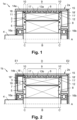
- Fig 1 shows a half sectional view of an electric machine 1, which comprises a machine housing 2a, a stator 3 fixedly arranged in the machine housing 2a, a rotor shaft 4 and a rotor 5 mounted on the rotor shaft 4, by which the rotor 5 is rotatably arranged in the machine housing 2a around a rotor axis A.
- the stator 3 comprises a stator lamination stack 6 and stator windings 7 arranged therein.
- the rotor 5 comprises a rotor lamination stack 8, in which rotor windings or rotor magnets can be arranged (not shown).
- the stator windings 7 comprise a stack section B, in which they run within the stator lamination stack 6, and stator winding heads C, C', where they run out of the stack section B and where they can have a bow shape.
- the electric machine 1 in the machine housing 2a comprises a first cooling system 9 based on a first cooling fluid around the stator lamination stack 6, and a separate second cooling system 10, 10' based on a separate second cooling fluid.
- the separate second cooling system 10, 10' runs over the entire circumference of the machine housing 2a.
- the separate second cooling system 10, 10' comprises spray nozzles or bores 11, 11', which are directed towards both stator winding heads C, C'.
- the spray nozzles or bores 11, 11' are directed radially inwards towards both stator winding heads C, C'.
- Spray jets 12 indicate that the second cooling fluid is sprayed on a radially outer side of the stator winding heads C, C'.
- the spray nozzles or bores 11, 11' are distributed all over the entire circumference of the machine housing 2a, in particular, an inner housing 13a.
- the machine housing 2a in detail comprises an inner housing part 13a and an outer housing part 14a, which is located radially outwards of the inner housing part 13a. Moreover, the machine housing 2a comprises a bearing shield 15, wherein bearings 16a, 16b for supporting the rotor shaft 4 are arranged in the outer housing part 14a and in the bearing shield 15.
- the machine housing 2a additionaly comprises a first cooling channel 17 and second cooling channels 18, 18'.
- the first cooling channel 17 is part of the first cooling system 9 and formed between the inner housing part 13a and the outer housing part 14a.
- the second cooling channels 18, 18' are part of the second cooling system 10, 10' and formed between the inner housing part 13a and the outer housing part 14a as well. Additionally, the second cooling channels 18, 18' are hydraulically connected to the spray nozzles or bores 11, 11'.
- the first cooling fluid can be water based and the second cooling fluid can be oil based.
- the first cooling fluid can be water based and the second cooling fluid can be oil based.
- the stator winding heads C, C' can be cooled and a lubricant can be brought into the interior of the electric machine 1.
- the thermal capacity of a water based cooling fluid is much higher than the thermal capacity of oil.
- Fig. 2 now shows another example of an electric machine 1b, which is similar to the electric machine 1a shown in Fig. 1 .
- the second cooling system 10 additionally comprises a cooling channel 18" and end section spray nozzles or bores 19 hydraulically connected thereto, which are directed towards at least one of the stator winding heads C, C'.
- the end section spray nozzles or bores 19 are directed axially inwards and spray the second cooling fluid on a front face of the stator winding head C.
- the machine housing 2a, 2b of the electric machine 1a, 1b can comprise a tube like section D around the stator 3 and end sections E1, E2 closing the tube like section D, wherein the inner housing part 13a and the outer housing part 14a preferably are part of the tube like section D, like this is depicted in Fig. 2 .
- the cooling channel 18" is solely arranged in the end section E1. However, there may also be an additional cooling channel 18" in the end section E2.
- one of the end sections E1, E2 (the end section E1) is one part with the tube like section D both forming a pot like section.
- the tube like section D and the end sections E1, E2 may be separate parts, meaning that the electric machine 1 may comprise two bearing shields 15.
- Fig. 3 now shows yet another example of an electric machine 1c, which is similar to the electric machine 1b shown in Fig. 2 .
- the second cooling system 10, 10' comprises an axial central shaft bore 20 in the rotor shaft 4 and rotor shaft spray nozzles or bores 21, 21' hydraulically connected thereto, which are directed towards the stator winding heads C, C'.
- the rotor shaft spray nozzles or bores 21, 21' are directed radially outwards and spray the second cooling fluid on a radially inner side of the stator winding heads C, C'.
- the rotation of the rotor 5 supports distribution of second cooling fluid.
- the rotor 5 can be cooled by the rotor shaft spray nozzles or bores 21, 21'.
- Figs. 4 and 5 now show different angular views of an inner housing part 13d, Fig. 4 from the side and Fig. 5 more from the front.
- the course of the first cooling channel 17 preferably at least has an axial component and can enclose an angle of 0° ⁇ ⁇ ⁇ 90° with the rotor axis A viewed in a radial direction.
- the course of the second cooling channel 18, 18' can enclose an angle of 90° ⁇ ⁇ > ⁇ with the rotor axis A viewed in a radial direction.
- ⁇ can be 90°.
- the first cooling channel 17 can run axially or helically and second channels 18, 18' in particular can form closed rings.
- the inner housing 13d comprises on one axial end a first flange extending radially.
- the first flange comprises an axial outlet (not shown) for the second cooling fluid.
- the inner housing 13d comprises external radial extensions (i.e the radial extensions extend from the inner housing away from the shaft). The radial extensions are designed to be put in contact with corresponding parts of another flange and/or the outer housing 14a.
- Fig. 6 finally shows an electric vehicle 22 with an electric machine 1 of the kind as defined hereinbefore, which is provided to propel the electric vehicle 25.
- the electric machine 1 is coupled to a gearbox 23, side shafts 24 and finally to the wheels 25.
- the electric machine 1 may be provided for powering the electric vehicle 22 permanently in a pure electric car or intermittently, e.g. in combination with a combustion engine in a hybrid car.
- the electric vehicle 22 comprises a first pump 26, a first cooler 27, a second pump 28 and a second cooler 29.
- the first pump 26, the first cooler 27 and the first cooling system 9 of the electric machine 1 are part of a first cooling circuit 30 of the vehicle 22.
- the second pump 28, the second cooler 29 and the second cooling system 10, 10' of the electric machine 1 are part of a second cooling circuit 31 of the vehicle 22. In this way, the first cooling fluid and the second cooling fluid can work independently.
- the invention is not limited to the embodiments disclosed hereinbefore, but combinations of the different variants are possible.
- the electric machine 1, 1a..1c and the electric vehicle 22 may have more or less parts than shown in the figures. It is also noted that the electric machine 1, 1a..1c and the electric vehicle 22 or parts thereof are not necessarily drawn to scale in the Figs. Moreover, the description may comprise subject matter of further independent inventions.
Landscapes
- Engineering & Computer Science (AREA)
- Power Engineering (AREA)
- Motor Or Generator Cooling System (AREA)
Abstract
An electric machine (1, 1a..1c) is disclosed, which comprises a machine housing (2a..2c), a stator (3) and a rotor (5). Stator windings (7) comprise a stack section (B), in which they run within the stator lamination stack (6), and stator winding heads (C, C'), where they run out of the stack section (B). The machine housing (2a..2c) comprises a first cooling system (9) based on a first cooling fluid around the stator lamination stack (6) and a separate second cooling system (10, 10') based on a separate second cooling fluid. The separate second cooling system (10, 10') comprises spray nozzles or bores (11, 11'), which are directed towards at least one of the stator winding heads (C, C'). Furthermore, a vehicle (23) with such an electric machine (1, 1a.. 1c) is disclosed.
Description
- The invention relates to an electric machine, which comprises a machine housing, a stator fixedly arranged in the machine housing, a rotor shaft and a rotor mounted on the rotor shaft, by which the rotor is rotatably arranged in the machine housing around a rotor axis. The stator comprises a stator lamination stack and stator windings arranged therein, wherein the stator windings comprise a stack section, in which they run within the stator lamination stack, and stator winding heads, where they run out of the stack section, for example in a bow shape. Moreover, the machine housing comprises a first cooling system based on a first cooling fluid around the stator lamination stack. Further on, the invention relates to a vehicle, driven by an electric machine of the above kind.
- An electric machine and a vehicle of the above kinds are generally known. Often, an electric machine has to be cooled, lubricated and shall be protected against oxidation. However, these different functions have very specific demands, and providing the same at a high level at the same time is hard to achieve. So, usually a tradeoff between the functions is done, what also means that often the potential of an electric machine is not fully exploited.
- Accordingly, an object of the invention is to provide an improved electric machine and an improved vehicle. In particular, a solution shall be proposed, which allows for cooling and lubrication of an electric machine as well as for avoiding of oxidation in the interior of the same.
- The object of the invention is solved by an electric machine as disclosed in the opening paragraph, wherein the machine housing additionally comprises a separate second cooling system based on a separate second cooling fluid, wherein the separate second cooling system comprises spray nozzles or bores, which are directed towards at least one of the stator winding heads. The spray nozzles or bores can be directed towards just one of the stator winding heads or to both stator winding heads.
- The object of the invention is also solved by a vehicle comprising an electric machine of the above kind which is designed to propel the vehicle. For example the first cooling system of the electric machine can be part of a first cooling circuit of the vehicle, and the second cooling system can be part of a separate second cooling circuit of the vehicle.
- By use of the proposed measures, the functions of cooling, lubrication and oxidation protection can be provided at a very high level at the same time. Generally, the first cooling fluid can be water based and the second cooling fluid can be oil based. In this way, on the one hand, a highly efficient cooling can be realized in the stack section of the stator, and on the other hand, in addition the stator winding heads can be cooled and a lubricant can be brought into the interior of the electric machine. It should be noted in this context that the thermal capacity of a water based cooling fluid is much higher than the thermal capacity of oil. Accordingly, also a cooling power of the first cooling system is higher than a cooling power of the second cooling system in this case. By the proposed measures, also unwanted oxidation can be avoided in the interior of the electric machine. Accordingly, the whole potential of an electric machine can be exploited.
- Further advantageous embodiments are disclosed in the claims and in the description as well as in the figures.
- In one embodiment, the machine housing can comprise a tube like section around the stator and end sections closing the tube like section, wherein the machine housing in the tube like section comprises
- an inner housing part,
- an outer housing part, which is located radially outwards of the inner housing part,
- a first cooling channel of the first cooling system, wherein the first cooling channel is formed between the inner housing part and the outer housing part, and
- a second cooling channel of the second cooling system and tube section spray nozzles or bores hydraulically connected thereto, which are directed towards at least one of the stator winding heads, wherein the second cooling channel is formed between the inner housing part and the outer housing part, too.
- In this way, the tube section spray nozzles or bores are directed radially inwards and spray the second cooling fluid on a radially outer side of the stator winding head(s).
- Preferably, the second cooling system in at least one of the end sections can comprise a cooling channel and end section spray nozzles or bores hydraulically connected thereto, which are directed towards at least one of the stator winding heads. In this way, end section spray nozzles or bores are provided, which are directed axially inwards and spray the second cooling fluid on a front face of the stator winding head(s). Accordingly, cooling can be improved even more.
- In yet another advantageous embodiment of the electric machine, the second cooling system can comprise an axial central shaft bore in the rotor shaft and rotor shaft spray nozzles or bores hydraulically connected thereto, which are directed towards at least one of the stator winding heads. Accordingly, the rotor shaft spray nozzles or bores are directed radially outwards and spray the second cooling fluid on a radially inner side of the stator winding head(s), wherein a rotation of the rotor supports distribution of second cooling fluid. In addition, the second cooling system can also be used for cooling the rotor.
- Generally, the
- the course of the first cooling channel can have at least an axial component and can enclose an angle of 0° ≤ α < 90° with the rotor axis viewed in a radial direction and
- the course of the second cooling channel can enclose an angle of 90° ≥ β > α with the rotor axis viewed in a radial direction, wherein in particular β = 90°.
- In other words, the first cooling channel runs axially or helically and second channel in particular forms a closed ring.
- Moreover, in one embodiment of the electric machine, one of the end sections is one part with the tube like section both forming a pot like section, whereas in another embodiment, the tube like section and the end sections are separate parts. That means, for the first variant just one additional bearing shield is needed, whereas two bearing shields are needed for the second variant.
- The invention now is described in more detail hereinafter with reference to particular embodiments, which the invention however is not limited to.
- Fig. 1
- shows a half sectional view of a first exemplary electric machine;
- Fig. 2
- like
Fig. 1 but with additional front sided spray nozzles; - Fig. 3
- like
Fig. 2 but with additional spray nozzles in the rotor shaft; - Fig. 4
- a detailed oblique view of an exemplary inner housing part from the side;
- Fig. 5
- the inner housing part of
Fig. 4 viewed more from the front and - Fig. 6
- shows a schematic view of an electric vehicle.
- Generally, same parts or similar parts are denoted with the same/similar names and reference signs. The features disclosed in the description apply to parts with the same/similar names respectively reference signs. Indicating the orientation and relative position is related to the associated figure.
-
Fig 1 shows a half sectional view of anelectric machine 1, which comprises amachine housing 2a, astator 3 fixedly arranged in themachine housing 2a, arotor shaft 4 and arotor 5 mounted on therotor shaft 4, by which therotor 5 is rotatably arranged in themachine housing 2a around a rotor axis A. Thestator 3 comprises astator lamination stack 6 andstator windings 7 arranged therein. Therotor 5 comprises arotor lamination stack 8, in which rotor windings or rotor magnets can be arranged (not shown). - The
stator windings 7 comprise a stack section B, in which they run within thestator lamination stack 6, and stator winding heads C, C', where they run out of the stack section B and where they can have a bow shape. Moreover, theelectric machine 1 in themachine housing 2a comprises afirst cooling system 9 based on a first cooling fluid around thestator lamination stack 6, and a separatesecond cooling system 10, 10' based on a separate second cooling fluid. The separatesecond cooling system 10, 10' runs over the entire circumference of themachine housing 2a. The separatesecond cooling system 10, 10' comprises spray nozzles or bores 11, 11', which are directed towards both stator winding heads C, C'. In the example ofFig. 1 , the spray nozzles or bores 11, 11' are directed radially inwards towards both stator winding heads C, C'. Sprayjets 12 indicate that the second cooling fluid is sprayed on a radially outer side of the stator winding heads C, C'. Advantageously, the spray nozzles or bores 11, 11' are distributed all over the entire circumference of themachine housing 2a, in particular, aninner housing 13a. - The
machine housing 2a in detail comprises aninner housing part 13a and anouter housing part 14a, which is located radially outwards of theinner housing part 13a. Moreover, themachine housing 2a comprises abearing shield 15, whereinbearings rotor shaft 4 are arranged in theouter housing part 14a and in thebearing shield 15. Themachine housing 2a additionaly comprises afirst cooling channel 17 andsecond cooling channels 18, 18'. Thefirst cooling channel 17 is part of thefirst cooling system 9 and formed between theinner housing part 13a and theouter housing part 14a. Thesecond cooling channels 18, 18' are part of thesecond cooling system 10, 10' and formed between theinner housing part 13a and theouter housing part 14a as well. Additionally, thesecond cooling channels 18, 18' are hydraulically connected to the spray nozzles or bores 11, 11'. - In the example of
Fig. 1 , there are twosecond cooling channels 18, 18' with connected spray nozzles or bores 11, 11', which are directed towards both stator winding heads C, C'. However, it may also be the case that there is just onecooling channel 18, 18' with connected spray nozzles or bores 11, 11', which are directed towards just one of the stator winding heads C, C' - Generally, the first cooling fluid can be water based and the second cooling fluid can be oil based. In this way, on the one hand, a highly efficient cooling can be realized in the stack section B of the
stator 5, and on the other hand, in addition the stator winding heads C, C' can be cooled and a lubricant can be brought into the interior of theelectric machine 1. It should be noted in this context that the thermal capacity of a water based cooling fluid is much higher than the thermal capacity of oil. By the proposed measures, also unwanted oxidation can be avoided in the interior of theelectric machine 1. -
Fig. 2 now shows another example of anelectric machine 1b, which is similar to theelectric machine 1a shown inFig. 1 . In contrast, thesecond cooling system 10 additionally comprises a coolingchannel 18" and end section spray nozzles or bores 19 hydraulically connected thereto, which are directed towards at least one of the stator winding heads C, C'. In detail, the end section spray nozzles or bores 19 are directed axially inwards and spray the second cooling fluid on a front face of the stator winding head C. - In general, the
machine housing electric machine stator 3 and end sections E1, E2 closing the tube like section D, wherein theinner housing part 13a and theouter housing part 14a preferably are part of the tube like section D, like this is depicted inFig. 2 . In the example ofFig. 2 , the coolingchannel 18" is solely arranged in the end section E1. However, there may also be anadditional cooling channel 18" in the end section E2. - In the examples of
Figs. 1 and 2 , one of the end sections E1, E2 (the end section E1) is one part with the tube like section D both forming a pot like section. However, the tube like section D and the end sections E1, E2 may be separate parts, meaning that theelectric machine 1 may comprise two bearing shields 15. -
Fig. 3 now shows yet another example of anelectric machine 1c, which is similar to theelectric machine 1b shown inFig. 2 . In contrast, thesecond cooling system 10, 10' comprises an axial central shaft bore 20 in therotor shaft 4 and rotor shaft spray nozzles or bores 21, 21' hydraulically connected thereto, which are directed towards the stator winding heads C, C'. Accordingly, the rotor shaft spray nozzles or bores 21, 21' are directed radially outwards and spray the second cooling fluid on a radially inner side of the stator winding heads C, C'. The rotation of therotor 5 supports distribution of second cooling fluid. In addition, therotor 5 can be cooled by the rotor shaft spray nozzles or bores 21, 21'. -
Figs. 4 and5 now show different angular views of aninner housing part 13d,Fig. 4 from the side andFig. 5 more from the front. As can particularly be seen inFig. 4 , the course of thefirst cooling channel 17 preferably at least has an axial component and can enclose an angle of 0° ≤ α < 90° with the rotor axis A viewed in a radial direction. Moreover, the course of thesecond cooling channel 18, 18' can enclose an angle of 90° ≥ β > α with the rotor axis A viewed in a radial direction. In particular, β can be 90°. In other words this means that thefirst cooling channel 17 can run axially or helically andsecond channels 18, 18' in particular can form closed rings. - Advantageously, the
inner housing 13d comprises on one axial end a first flange extending radially. The first flange comprises an axial outlet (not shown) for the second cooling fluid. On the other axial end, theinner housing 13d comprises external radial extensions (i.e the radial extensions extend from the inner housing away from the shaft). The radial extensions are designed to be put in contact with corresponding parts of another flange and/or theouter housing 14a. -
Fig. 6 finally shows anelectric vehicle 22 with anelectric machine 1 of the kind as defined hereinbefore, which is provided to propel theelectric vehicle 25. In detail, theelectric machine 1 is coupled to agearbox 23,side shafts 24 and finally to thewheels 25. Theelectric machine 1 may be provided for powering theelectric vehicle 22 permanently in a pure electric car or intermittently, e.g. in combination with a combustion engine in a hybrid car. - Further on, the
electric vehicle 22 comprises afirst pump 26, afirst cooler 27, asecond pump 28 and asecond cooler 29. Thefirst pump 26, thefirst cooler 27 and thefirst cooling system 9 of theelectric machine 1 are part of afirst cooling circuit 30 of thevehicle 22. Thesecond pump 28, thesecond cooler 29 and thesecond cooling system 10, 10' of theelectric machine 1 are part of asecond cooling circuit 31 of thevehicle 22. In this way, the first cooling fluid and the second cooling fluid can work independently. - It is also noted that the invention is not limited to the embodiments disclosed hereinbefore, but combinations of the different variants are possible. In reality, the
electric machine electric vehicle 22 may have more or less parts than shown in the figures. It is also noted that theelectric machine electric vehicle 22 or parts thereof are not necessarily drawn to scale in the Figs. Moreover, the description may comprise subject matter of further independent inventions. - Finally, it should be noted that the term "comprising" does not exclude other elements and the use of articles "a" or "an" does not exclude a plurality. Also elements described in association with different embodiments may be combined. It should also be noted that reference signs in the claims should not be construed as limiting the scope of the claims.
-
- 1, 1a..1c
- electric machine
- 2a..2c
- machine housing
- 3
- stator
- 4
- rotor shaft
- 5
- rotor
- 6
- stator lamination stack
- 7
- stator winding
- 8
- rotor lamination stack
- 9
- first cooling system
- 10, 10'
- second cooling system
- 11, 11'
- tube section spray nozzles / bores
- 12
- spray jet
- 13a..13d
- inner housing part
- 14a..14c
- outer housing part
- 15
- bearing shield
- 16a, 16b
- (roller)bearing
- 17
- first cooling channel
- 18..18"
- second cooling channel
- 19
- end section spray nozzles / bores
- 20
- central shaft bore
- 21, 21'
- rotor shaft spray nozzles / bores
- 22
- vehicle
- 23
- gearbox
- 24
- side shaft
- 25
- wheel
- 26
- first pump
- 27
- first cooler
- 28
- second pump
- 29
- second cooler
- 30
- first cooling circuit
- 31
- second cooling circuit
- A
- rotor axis
- B
- stack section
- C, C'
- stator winding head
- D
- tube like section
- E1, E2
- end section
- α
- angle between course of first cooling channel and rotor axis
- β
- angle between course of second cooling channel and rotor axis
Claims (10)
- Electric machine (1, 1a..1c), comprising a machine housing (2a..2c), a stator (3) fixedly arranged in the machine housing (2a..2c), a rotor shaft (4) and a rotor (5) mounted on the rotor shaft (4), by which the rotor (5) is rotatably arranged in the machine housing (2a..2c) around a rotor axis (A),- wherein the stator (3) comprises a stator lamination stack (6) and stator windings (7) arranged therein,- wherein the stator windings (7) comprise a stack section (B), in which they run within the stator lamination stack (6), and stator winding heads (C, C'), where they run out of the stack section (B) and- wherein the machine housing (2a..2c) comprises a first cooling system (9) based on a first cooling fluid around the stator lamination stack (6),
characterized in that- the machine housing (2a..2c) comprises a separate second cooling system (10, 10') based on a separate second cooling fluid, wherein the separate second cooling system (10, 10') comprises spray nozzles or bores (11, 11'), which are directed towards at least one of the stator winding heads (C, C'). - Electric machine (1, 1a..1c) as claimed in claim 1, characterized in that the first cooling fluid is water based and the second cooling fluid is oil based.
- Electric machine (1, 1a..1c) as claimed in claim 1 or 2, characterized in that the spray nozzles or bores (11, 11') are directed towards both stator winding heads (C, C').
- Electric machine (1, 1a..1c) as claimed in claim 1 to 3, characterized in that the machine housing (2a..2c) comprises a tube like section (D) around the stator (3) and end sections (E1, E2) closing the tube like section (D), wherein the machine housing (2a..2c) in the tube like section (D) comprises- an inner housing part (13a..13d),- an outer housing part (14a..14c), which is located radially outwards of the inner housing part (13a..13d),- a first cooling channel (17) of the first cooling system (9), wherein the first cooling channel (17) is formed between the inner housing part (13a.. 13d) and the outer housing part (14a..14c), and- a second cooling channel (18, 18') of the second cooling system (10, 10') and tube section spray nozzles or bores (11, 11') hydraulically connected thereto, which are directed towards at least one of the stator winding heads (C, C'), wherein the second cooling channel (18, 18') is formed between the inner housing part (13a..13d) and the outer housing part (14a.. 14c), too.
- Electric machine (1, 1a..1c) as claimed in claim 4, characterized in that- the course of the first cooling channel (17) at least has an axial component and encloses an angle of 0° ≤ α < 90° with the rotor axis (A) viewed in a radial direction and- the course of the second cooling channel (18, 18') encloses an angle of 90° ≥ β > α with the rotor axis (A) viewed in a radial direction, wherein in particular β = 90°.
- Electric machine (1, 1a..1c) as claimed in claim 4 or 5, characterized in that the second cooling system (10, 10') in at least one of the end sections (E1, E2) comprises a cooling channel (18") and end section spray nozzles or bores (19) hydraulically connected thereto, which are directed towards at least one of the stator winding heads (C, C').
- Electric machine (1, 1a..1c) as claimed in any one of claims 4 to 6, characterized in that- one of the end sections (E1, E2) is one part with the tube like section (D) both forming a pot like section or- the tube like section (D) and the end sections (E1, E2) are separate parts.
- Electric machine (1, 1a..1c) as claimed in any one of claims 1 to 7, characterized in that the second cooling system (10, 10') comprises an axial central shaft bore (20) in the rotor shaft (4) and rotor shaft spray nozzles or bores (21, 21') hydraulically connected thereto, which are directed towards at least one of the stator winding heads (C, C').
- Vehicle (22), driven by an electric machine (1, 1a..1c) as claimed in any one of claims 1 to 8.
- Vehicle (22) according to claim 9, characterized in that the first cooling system (9) is part of a first cooling circuit (30) of the vehicle (22), and the second cooling system (10, 10') is part of a separate second cooling circuit (31) of the vehicle (22).
Applications Claiming Priority (1)
| Application Number | Priority Date | Filing Date | Title |
|---|---|---|---|
| DE102023134860.4A DE102023134860A1 (en) | 2023-12-12 | 2023-12-12 | Electric machine and vehicle with improved cooling system |
Publications (1)
| Publication Number | Publication Date |
|---|---|
| EP4572104A1 true EP4572104A1 (en) | 2025-06-18 |
Family
ID=93843681
Family Applications (1)
| Application Number | Title | Priority Date | Filing Date |
|---|---|---|---|
| EP24218411.7A Pending EP4572104A1 (en) | 2023-12-12 | 2024-12-09 | Electric machine and vehicle with improved cooling system |
Country Status (4)
| Country | Link |
|---|---|
| US (1) | US20250192639A1 (en) |
| EP (1) | EP4572104A1 (en) |
| CN (1) | CN120150416A (en) |
| DE (1) | DE102023134860A1 (en) |
Citations (6)
| Publication number | Priority date | Publication date | Assignee | Title |
|---|---|---|---|---|
| JP6072866B1 (en) * | 2015-08-26 | 2017-02-01 | 三菱電機株式会社 | Rotating electric machine |
| JP6914904B2 (en) * | 2018-11-09 | 2021-08-04 | 本田技研工業株式会社 | Rotating electric machine stator unit |
| US20210313862A1 (en) * | 2018-08-30 | 2021-10-07 | Jheeco E-Drive Ag | Cooling device, motor housing and motor unit |
| CN114301236A (en) * | 2021-12-30 | 2022-04-08 | 中克骆瑞新能源科技有限公司 | Oil-cooled flat wire motor with three-phase lead wire cooling function |
| CN115021437A (en) * | 2022-05-26 | 2022-09-06 | 珠海格力电器股份有限公司 | Stator module, motor and have its car |
| CN116191751A (en) * | 2023-03-20 | 2023-05-30 | 一汽解放汽车有限公司 | Motors, cooling systems and vehicles |
Family Cites Families (3)
| Publication number | Priority date | Publication date | Assignee | Title |
|---|---|---|---|---|
| US10272767B1 (en) * | 2018-03-23 | 2019-04-30 | Sf Motors, Inc. | Dual loop liquid cooling of integrated electric drivetrain |
| DE102021125659A1 (en) * | 2021-10-04 | 2023-04-06 | Bayerische Motoren Werke Aktiengesellschaft | Cooling arrangements for an electromotive drive unit and its components |
| DE102022101887A1 (en) * | 2022-01-27 | 2023-07-27 | Bayerische Motoren Werke Aktiengesellschaft | Spray oil cooling device for a stator core periphery |
-
2023
- 2023-12-12 DE DE102023134860.4A patent/DE102023134860A1/en active Pending
-
2024
- 2024-12-09 EP EP24218411.7A patent/EP4572104A1/en active Pending
- 2024-12-12 CN CN202411828492.3A patent/CN120150416A/en active Pending
- 2024-12-12 US US18/978,356 patent/US20250192639A1/en active Pending
Patent Citations (6)
| Publication number | Priority date | Publication date | Assignee | Title |
|---|---|---|---|---|
| JP6072866B1 (en) * | 2015-08-26 | 2017-02-01 | 三菱電機株式会社 | Rotating electric machine |
| US20210313862A1 (en) * | 2018-08-30 | 2021-10-07 | Jheeco E-Drive Ag | Cooling device, motor housing and motor unit |
| JP6914904B2 (en) * | 2018-11-09 | 2021-08-04 | 本田技研工業株式会社 | Rotating electric machine stator unit |
| CN114301236A (en) * | 2021-12-30 | 2022-04-08 | 中克骆瑞新能源科技有限公司 | Oil-cooled flat wire motor with three-phase lead wire cooling function |
| CN115021437A (en) * | 2022-05-26 | 2022-09-06 | 珠海格力电器股份有限公司 | Stator module, motor and have its car |
| CN116191751A (en) * | 2023-03-20 | 2023-05-30 | 一汽解放汽车有限公司 | Motors, cooling systems and vehicles |
Also Published As
| Publication number | Publication date |
|---|---|
| CN120150416A (en) | 2025-06-13 |
| US20250192639A1 (en) | 2025-06-12 |
| DE102023134860A1 (en) | 2025-06-12 |
Similar Documents
| Publication | Publication Date | Title |
|---|---|---|
| US11303174B2 (en) | Rotor for an electric machine | |
| US11936277B2 (en) | Combined power system | |
| US20160091082A1 (en) | Planetary gear | |
| US9553493B2 (en) | Rotating electric machine | |
| EP3696952B1 (en) | Dual fluid rotating shaft | |
| EP3961875B1 (en) | Electric-machine shaft | |
| US11732605B2 (en) | Combined power system | |
| EP2412080B1 (en) | Bearing assembly | |
| US20160172931A1 (en) | Alternator rotor to stator integrated hrdrodynamic bearing | |
| US8550862B2 (en) | Ship propulsion system having a pump jet | |
| US11855512B2 (en) | Combined power system | |
| JP2009220771A (en) | Generator motor | |
| US11876411B2 (en) | Combined power system | |
| US20240396403A1 (en) | Hollow shaft for a rotor of electric motor | |
| CN114465403A (en) | Electric machine with circumferential cooling jacket | |
| US20220247273A1 (en) | Electric machine | |
| US20120013206A1 (en) | Cooling System and Method for an Electric Machine Module | |
| WO2016199821A1 (en) | Rotary machine | |
| US20250192639A1 (en) | Electric machine and vehicle with improved cooling system | |
| KR20110097910A (en) | Ship propulsion system with pump jet | |
| EP1484518B1 (en) | Bearing lubricating structure of electric motor | |
| CN117432916A (en) | Electric drive assembly and vehicle with cooling lubricating oil circuit structure | |
| WO2016199822A1 (en) | Rotary machine | |
| US11634997B2 (en) | Combined power system | |
| JP2010007516A (en) | Electric oil pump |
Legal Events
| Date | Code | Title | Description |
|---|---|---|---|
| PUAI | Public reference made under article 153(3) epc to a published international application that has entered the european phase |
Free format text: ORIGINAL CODE: 0009012 |
|
| STAA | Information on the status of an ep patent application or granted ep patent |
Free format text: STATUS: EXAMINATION IS IN PROGRESS |
|
| 17P | Request for examination filed |
Effective date: 20241209 |
|
| AK | Designated contracting states |
Kind code of ref document: A1 Designated state(s): AL AT BE BG CH CY CZ DE DK EE ES FI FR GB GR HR HU IE IS IT LI LT LU LV MC ME MK MT NL NO PL PT RO RS SE SI SK SM TR |