EP4572097A1 - Rotor für eine elektrische maschine und elektrische drehmaschine mit axialfluss - Google Patents
Rotor für eine elektrische maschine und elektrische drehmaschine mit axialfluss Download PDFInfo
- Publication number
- EP4572097A1 EP4572097A1 EP24219832.3A EP24219832A EP4572097A1 EP 4572097 A1 EP4572097 A1 EP 4572097A1 EP 24219832 A EP24219832 A EP 24219832A EP 4572097 A1 EP4572097 A1 EP 4572097A1
- Authority
- EP
- European Patent Office
- Prior art keywords
- rotor
- orthoradial
- grooves
- permanent magnet
- groove
- Prior art date
- Legal status (The legal status is an assumption and is not a legal conclusion. Google has not performed a legal analysis and makes no representation as to the accuracy of the status listed.)
- Pending
Links
Images

Classifications
-
- H—ELECTRICITY
- H02—GENERATION; CONVERSION OR DISTRIBUTION OF ELECTRIC POWER
- H02K—DYNAMO-ELECTRIC MACHINES
- H02K1/00—Details of the magnetic circuit
- H02K1/06—Details of the magnetic circuit characterised by the shape, form or construction
- H02K1/22—Rotating parts of the magnetic circuit
- H02K1/28—Means for mounting or fastening rotating magnetic parts on to, or to, the rotor structures
- H02K1/30—Means for mounting or fastening rotating magnetic parts on to, or to, the rotor structures using intermediate parts, e.g. spiders
-
- H—ELECTRICITY
- H02—GENERATION; CONVERSION OR DISTRIBUTION OF ELECTRIC POWER
- H02K—DYNAMO-ELECTRIC MACHINES
- H02K1/00—Details of the magnetic circuit
- H02K1/06—Details of the magnetic circuit characterised by the shape, form or construction
- H02K1/22—Rotating parts of the magnetic circuit
- H02K1/27—Rotor cores with permanent magnets
- H02K1/2793—Rotors axially facing stators
- H02K1/2795—Rotors axially facing stators the rotor consisting of two or more circumferentially positioned magnets
-
- H—ELECTRICITY
- H02—GENERATION; CONVERSION OR DISTRIBUTION OF ELECTRIC POWER
- H02K—DYNAMO-ELECTRIC MACHINES
- H02K1/00—Details of the magnetic circuit
- H02K1/06—Details of the magnetic circuit characterised by the shape, form or construction
- H02K1/22—Rotating parts of the magnetic circuit
- H02K1/27—Rotor cores with permanent magnets
- H02K1/2793—Rotors axially facing stators
- H02K1/2795—Rotors axially facing stators the rotor consisting of two or more circumferentially positioned magnets
- H02K1/2796—Rotors axially facing stators the rotor consisting of two or more circumferentially positioned magnets where both axial sides of the rotor face a stator
-
- H—ELECTRICITY
- H02—GENERATION; CONVERSION OR DISTRIBUTION OF ELECTRIC POWER
- H02K—DYNAMO-ELECTRIC MACHINES
- H02K1/00—Details of the magnetic circuit
- H02K1/06—Details of the magnetic circuit characterised by the shape, form or construction
- H02K1/22—Rotating parts of the magnetic circuit
- H02K1/27—Rotor cores with permanent magnets
- H02K1/2793—Rotors axially facing stators
- H02K1/2795—Rotors axially facing stators the rotor consisting of two or more circumferentially positioned magnets
- H02K1/2798—Rotors axially facing stators the rotor consisting of two or more circumferentially positioned magnets where both axial sides of the stator face a rotor
-
- H—ELECTRICITY
- H02—GENERATION; CONVERSION OR DISTRIBUTION OF ELECTRIC POWER
- H02K—DYNAMO-ELECTRIC MACHINES
- H02K15/00—Processes or apparatus specially adapted for manufacturing, assembling, maintaining or repairing of dynamo-electric machines
- H02K15/02—Processes or apparatus specially adapted for manufacturing, assembling, maintaining or repairing of dynamo-electric machines of stator or rotor bodies
- H02K15/03—Processes or apparatus specially adapted for manufacturing, assembling, maintaining or repairing of dynamo-electric machines of stator or rotor bodies having permanent magnets
-
- H—ELECTRICITY
- H02—GENERATION; CONVERSION OR DISTRIBUTION OF ELECTRIC POWER
- H02K—DYNAMO-ELECTRIC MACHINES
- H02K16/00—Machines with more than one rotor or stator
- H02K16/02—Machines with one stator and two or more rotors
-
- H—ELECTRICITY
- H02—GENERATION; CONVERSION OR DISTRIBUTION OF ELECTRIC POWER
- H02K—DYNAMO-ELECTRIC MACHINES
- H02K16/00—Machines with more than one rotor or stator
- H02K16/04—Machines with one rotor and two stators
-
- H—ELECTRICITY
- H02—GENERATION; CONVERSION OR DISTRIBUTION OF ELECTRIC POWER
- H02K—DYNAMO-ELECTRIC MACHINES
- H02K21/00—Synchronous motors having permanent magnets; Synchronous generators having permanent magnets
- H02K21/12—Synchronous motors having permanent magnets; Synchronous generators having permanent magnets with stationary armatures and rotating magnets
- H02K21/24—Synchronous motors having permanent magnets; Synchronous generators having permanent magnets with stationary armatures and rotating magnets with magnets axially facing the armatures, e.g. hub-type cycle dynamos
Definitions
- the invention relates to the field of axial flux rotating electrical machines, in particular for an electric or hybrid vehicle.
- the invention is more particularly concerned with the rotor of these axial flux rotating electrical machines.
- Known axial flux rotating electrical machines have permanent magnets in the rotor(s) of the machine. These permanent magnets are subjected to the magnetic fields generated by the stator coils so as to drive the rotor into rotation.
- Permanent magnets used in the automotive industry are particularly large, which has the notable consequence of generating significant eddy currents during their use. These eddy currents reduce the system's performance by generating heat in the magnets, which can also damage the system.
- the document CN109921525A plans to solve this problem of eddy current losses by making orthoradial grooves in the permanent magnet over the entire surface of the magnet. These orthoradial grooves make it possible to reduce eddy current losses but weaken the mechanical strength of the permanent magnet, making it difficult to handle.
- One idea behind the invention is to limit eddy current losses from the permanent magnets of an axial flux rotating electrical machine.
- Another idea behind the invention is to facilitate the manufacture of permanent magnets for an axial flux rotating electrical machine.
- Another idea behind the invention is to facilitate the handling of permanent magnets when positioning them on the rotor disc.
- the invention provides a rotor for an axial flux electrical machine, intended to be mounted so as to be able to rotate about an axis X and positioned axially opposite a stator, the rotor comprising a disk integral in rotation with an output shaft and a plurality of permanent magnets distributed about the axis X, each permanent magnet having the shape of a truncated disk sector; wherein at least one of the permanent magnets of said plurality of permanent magnets is produced in a single piece and consists of a holding portion and a grooved portion arranged in a radial direction of the axis X outside the holding portion, said permanent magnet comprising a plurality of grooves, the entire plurality of grooves being produced on the grooved portion, wherein the holding portion has a radial dimension of between 10 and 50% of a radial dimension of said permanent magnet, said permanent magnet having a first surface located opposite the stator, and a second surface opposite the first surface, and wherein the plurality of grooves comprises at
- the grooves present on the permanent magnet make it possible to significantly limit eddy current losses and therefore improve the efficiency of the rotating electrical machine.
- the holding portion which is therefore free of grooves likely to weaken it, the permanent magnet can be easily handled by this particularly robust holding portion.
- the holding portion being located closest to the X axis, the grooved portion is located in the radially outer zone where eddy current losses are the greatest.
- the position of the grooves is optimized to limit these losses.
- the permanent magnet being a single piece, its manufacture is facilitated. Thus, all of these characteristics make it possible to obtain a good compromise between reducing eddy current losses and ease of manufacturing and handling of permanent magnets.
- such a rotor may comprise one or more of the following features.
- several permanent magnets of said plurality of permanent magnets are produced in a single piece and each consist of a holding portion and a grooved portion arranged radially outside the holding portion, said permanent magnets each comprising a plurality of grooves, the entire plurality of grooves being produced on the grooved portion.
- each permanent magnet of said plurality of permanent magnets is produced in a single piece and consists of a holding portion and a grooved portion arranged radially outside the holding portion, each permanent magnet comprising a plurality of grooves, the entire plurality of grooves being produced on the grooved portion.
- the disc comprises housings distributed all around the X axis, the permanent magnets each being arranged in one of the housings of the disc.
- the radial groove is made in a thickness direction parallel to the X axis from the first surface of said permanent magnet.
- the radial groove is made as close as possible to the stator in the area where it is advantageous to limit eddy current losses.
- the radial groove is made in a transverse manner from the first surface to the second surface of said permanent magnet.
- the plurality of grooves comprises a plurality of radial grooves spaced apart from each other.
- the plurality of grooves comprises a plurality of orthoradial grooves spaced apart from each other.
- the orthoradial groove is made in a thickness direction parallel to the X axis from the first surface of the permanent magnet.
- the orthoradial groove is made as close as possible to the stator in the area where it is advantageous to limit eddy current losses.
- the orthoradial groove extends in a thickness direction parallel to the X axis over only a portion of one dimension of the permanent magnet in the thickness direction.
- the orthoradial groove has a dimension in a thickness direction parallel to the X axis of between 10% and 90% of a dimension of the permanent magnet in the thickness direction.
- the orthoradial groove is a first orthoradial groove
- the plurality of grooves comprises a second orthoradial groove having a dimension in the thickness direction of between 10% and 90% of a dimension of the permanent magnet in the thickness direction, the second orthoradial groove being formed in the thickness direction from the second surface of the permanent magnet, the first orthoradial groove and the second orthoradial groove being spaced apart from each other by a non-zero distance in the radial direction.
- the plurality of grooves comprises a plurality of first orthoradial grooves and a plurality of second orthoradial grooves, the first orthoradial grooves being alternated with the second orthoradial grooves in the radial direction.
- the permanent magnets and the rotor disc are held in position relative to each other using an overmolding.
- the invention also provides a motor vehicle comprising an aforementioned electric machine.
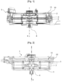
- FIG. 1 represents an axial flux rotating electrical machine 1, of the permanent magnet type comprising a casing 10 defining an internal space 11, two stators 2 and a rotor 3 positioned in the internal space 11, the stators 2 being placed on either side of the rotor 3 and axially opposite the rotor 3.
- the rotor 3 is axially spaced from the two stators so as to form two air gaps.
- the axial flux electric machine 1 is configured to operate in motor mode and in generator mode. This is a permanent magnet synchronous motor, for the propulsion of an electric vehicle.
- a vehicle is any vehicle that can transport goods or people, such as a car, truck, bicycle or drone.
- the power of the electric machine may be between 4 kW and 850 kW.
- the electric machine advantageously has an operating voltage of less than 60 Volts, and preferably 48 Volts.
- the torque provided by the electric machine is between 30 N.m and 2000 N.m.
- the electric machine may have an operating voltage of more than 60 V, or even more than 80 V or more than 100 V, in particular 300 V or more.
- the power of the machine may be between 60 kW and 300 kW.
- the axial flux electric machine 1 comprises an output shaft 4 extending along an axis X, integral with the rotor 3 and passing through the rotor 3 and the stators 2.
- the output shaft 4 comprises an output pinion which meshes with a reducer (not shown).
- the rotor 3 comprises a disc 5 integral in rotation with the output shaft 4 and comprising an orifice 6 crossed by the output shaft 4.
- the disc 5 also comprises housings 7 distributed regularly around the axis X in which permanent magnets 8 are arranged which have, for example, a disc sector shape.
- the rotor 3 will be more particularly described in relation to the figures 2 to 4 .
- the stators 2 each comprise a stator body provided with a plurality of electrical windings and a plurality of teeth carrying the electrical windings.
- a housing is configured to carry the plurality of teeth.
- the windings on the teeth together form a general stator winding, for example of the three-phase type. These windings are made by turns of electrical wire around each tooth.
- the windings are configured to be electrically powered so as to generate a magnetic field capable of producing, with the rotor 3 of the axial flux electric machine 1, an output torque.
- FIG. 2 illustrates another embodiment of the axial flux rotating electric machine 1.
- the axial flux rotating electric machine 1 of the Figure 2 comprises a stator 2 and two rotors 3 placed on either side of the stator 2, axially facing the stator 2.
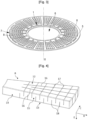
- FIG. 3 more particularly represents the disc 5 of the rotor 3 and the associated permanent magnets 8.
- the permanent magnets 8 each have the shape of a truncated disk sector and are distributed regularly around the X axis.
- Each of the permanent magnets 8 is placed in one of the housings 7 of the disk 5.
- the housings 7 thus have shapes complementary to the permanent magnets 8.
- the permanent magnets 8 are arranged in the housings 7 so that a first surface 12 of the permanent magnets 8 projects from one side of the disc 5 which is intended to be opposite one of the stators 2 and that a second surface 13 opposite the first surface 12 projects from another side of the disc 5 which is intended to be opposite the other of the stators 2 in the case of the electric machine 1 with two stators of the Figure 1 .
- the permanent magnets 8 are fixed to a flange and have a single surface projecting from the disc 5 and intended to be opposite the stator 2.
- each permanent magnet 8 is made in a single piece and is made up of two portions: a holding portion 14 and a grooved portion 15 which is arranged radially outside the holding portion 14.
- Each permanent magnet 8 also comprises a plurality of grooves and all of these grooves are made on the grooved portion 15 so that the holding portion 14 is free of grooves.
- the holding portion 14 advantageously has a radial dimension, measured in the radial direction R, of between 10 and 30% of a radial dimension of the permanent magnet 8.
- the radial dimension of the holding portion 14 is approximately 26% of the radial dimension of the permanent magnet 8.
- the grooved portion 15 has a radial dimension complementary to the radial dimension of the holding portion 14, i.e. in the example approximately 74% of the total radial dimension of the permanent magnet 8.
- the permanent magnet 8 comprises among the plurality of grooves, radial grooves 16 which extend in the radial direction R and spaced from each other.
- the radial grooves 16 are three in number and thus cut the grooved portion 15 of the permanent magnet 8 in an orthoradial direction O into four parts. In other embodiments, this number could be more or less important depending on the dimension of the permanent magnet 8.
- Each radial groove 16 is made in a through manner in a thickness direction E parallel to the axis X from the first surface 12 to the second surface 13.
- the permanent magnet 8 comprises among the plurality of grooves, orthoradial grooves extending in the orthoradial direction O, parallel to each other and spaced apart from each other.
- the permanent magnet 8 comprises first orthoradial grooves 17 formed in the thickness direction E from the first surface 12, and second orthoradial grooves 18 formed in the thickness direction E from the second surface 13.
- first orthoradial grooves 17 are alternated with the second orthoradial grooves 18 in the radial direction R.
- the first orthoradial grooves 17 and the second orthoradial grooves 18 each advantageously have a dimension in the thickness direction E of between 10 and 90% of a dimension in the thickness direction E of the permanent magnet 8.
- the dimension in the thickness direction of the orthoradial grooves 17, 18 is about 60% of the dimension in the thickness direction E of the permanent magnet 8.
- the first orthoradial grooves 17 are six in number and the second orthoradial grooves 18 are also six in number. In other embodiments, this number could be more or less important depending on the dimension of the permanent magnet 8. In addition, the number of the first orthoradial grooves 17 could be different from the number of the second orthoradial grooves 18, with for example five first orthoradial grooves 17 and four second orthoradial grooves 18.
- the grooved portion 15 may comprise only first orthoradial grooves 17 or second orthoradial grooves 18, for example in the case where the electrical machine 1 comprises a single stator 2 and two rotors 3.
- the grooves 16, 17, 18 are for example produced by wire cutting or laser cutting operations.
- FIG. 5 represents the rotor 3 after an overmolding step aimed at holding the permanent magnets 8 in position in the housings 7 of the disc 5.
- the disc 5 makes it possible to position the magnets circumferentially and radially before overmolding, and as visible in this Figure 5 , the entire disc 5 and permanent magnets 8 of the rotor 3 are enveloped by a layer of resin 19, preferably made of plastic, during an overmolding step which precisely blocks the positions of the different permanent magnets 8.
- the holes 20 visible on the Figure 5 represent the location of pins which are positioned in the mold to ensure a precise position of the permanent magnets 8 during overmolding.
Landscapes
- Engineering & Computer Science (AREA)
- Power Engineering (AREA)
- Manufacturing & Machinery (AREA)
- Permanent Field Magnets Of Synchronous Machinery (AREA)
Applications Claiming Priority (1)
| Application Number | Priority Date | Filing Date | Title |
|---|---|---|---|
| FR2314200A FR3157025A1 (fr) | 2023-12-14 | 2023-12-14 | Rotor pour machine électrique et machine électrique tournante à flux axial |
Publications (1)
| Publication Number | Publication Date |
|---|---|
| EP4572097A1 true EP4572097A1 (de) | 2025-06-18 |
Family
ID=90720885
Family Applications (1)
| Application Number | Title | Priority Date | Filing Date |
|---|---|---|---|
| EP24219832.3A Pending EP4572097A1 (de) | 2023-12-14 | 2024-12-13 | Rotor für eine elektrische maschine und elektrische drehmaschine mit axialfluss |
Country Status (3)
| Country | Link |
|---|---|
| EP (1) | EP4572097A1 (de) |
| CN (1) | CN120165518A (de) |
| FR (1) | FR3157025A1 (de) |
Citations (5)
| Publication number | Priority date | Publication date | Assignee | Title |
|---|---|---|---|---|
| EP1065777B1 (de) * | 1999-06-30 | 2004-10-13 | Shin-Etsu Chemical Co., Ltd. | Auf seltenen Erden basierender gesinterter Dauermagnet und mit einem solchen Magnet versehener Synchronmotor |
| WO2018172633A1 (fr) | 2017-03-22 | 2018-09-27 | Whylot Sas | Moteur ou génératrice électromagnétique comportant un rotor à structures aimantées comprenant des aimants unitaires et un stator à bobinages concentriques |
| CN109921525A (zh) | 2019-03-19 | 2019-06-21 | 甘长泉 | 一种减少涡流效应的电机磁体环及磁体 |
| FR3119703A1 (fr) * | 2021-02-05 | 2022-08-12 | Renault S.A.S | Procédé de fabrication d’une structure d’aimant à plusieurs aimants unitaires |
| FR3127344A1 (fr) * | 2021-09-21 | 2023-03-24 | Renault S.A.S. | procédé de surmoulage d’un élément à pôles magnétiques pour un rotor d’une machine électrique et procédé de fabrication d’un tel rotor |
-
2023
- 2023-12-14 FR FR2314200A patent/FR3157025A1/fr active Pending
-
2024
- 2024-12-13 EP EP24219832.3A patent/EP4572097A1/de active Pending
- 2024-12-16 CN CN202411849742.1A patent/CN120165518A/zh active Pending
Patent Citations (5)
| Publication number | Priority date | Publication date | Assignee | Title |
|---|---|---|---|---|
| EP1065777B1 (de) * | 1999-06-30 | 2004-10-13 | Shin-Etsu Chemical Co., Ltd. | Auf seltenen Erden basierender gesinterter Dauermagnet und mit einem solchen Magnet versehener Synchronmotor |
| WO2018172633A1 (fr) | 2017-03-22 | 2018-09-27 | Whylot Sas | Moteur ou génératrice électromagnétique comportant un rotor à structures aimantées comprenant des aimants unitaires et un stator à bobinages concentriques |
| CN109921525A (zh) | 2019-03-19 | 2019-06-21 | 甘长泉 | 一种减少涡流效应的电机磁体环及磁体 |
| FR3119703A1 (fr) * | 2021-02-05 | 2022-08-12 | Renault S.A.S | Procédé de fabrication d’une structure d’aimant à plusieurs aimants unitaires |
| FR3127344A1 (fr) * | 2021-09-21 | 2023-03-24 | Renault S.A.S. | procédé de surmoulage d’un élément à pôles magnétiques pour un rotor d’une machine électrique et procédé de fabrication d’un tel rotor |
Also Published As
| Publication number | Publication date |
|---|---|
| FR3157025A1 (fr) | 2025-06-20 |
| CN120165518A (zh) | 2025-06-17 |
Similar Documents
| Publication | Publication Date | Title |
|---|---|---|
| FR3064423B1 (fr) | Rotor pour moteur ou generatrice electromagnetique a structure alveolaire comportant des alveoles pour le logement d'aimants respectifs | |
| EP2372873B1 (de) | Elektrische rotierende Synchronmaschine mit Dauermagneten und Strömungskonzentration | |
| EP3403314A1 (de) | Stator für eine axialströmungsmaschine mit einem statorring aus modulen | |
| EP2786469B1 (de) | Rotor für eine elektrische drehende maschine und elektrische drehende maschine mit einem derartigen rotor | |
| EP4264781B1 (de) | Magnetpol-element mit einer anordnung aus mehreren einzelmagneten für den rotor einer elektrischen axialflussmaschine | |
| WO2024132599A1 (fr) | Stator de machine électrique à flux axial | |
| WO2024132600A1 (fr) | Stator de machine électrique à flux axial | |
| EP4364280B1 (de) | Verfahren zur herstellung eines elements mit magnetpolen | |
| EP2283561B1 (de) | Rotor für elektrische drehmaschine mit interpolaren strukturen mit verringerter masse | |
| EP1351367A1 (de) | Elektrische Maschine mit modularem Stator und/oder Rotor sowie Kraftfahrzeug-Kühler unter Verwendung einer solchen Maschine | |
| EP4572097A1 (de) | Rotor für eine elektrische maschine und elektrische drehmaschine mit axialfluss | |
| EP4315565A1 (de) | Rotor für eine elektrische drehmaschine | |
| FR3123519A1 (fr) | Machine electrique tournante à configuration co-axiale | |
| EP3607640B1 (de) | Rotor für elektrische maschine mit internen permanentmagneten | |
| EP2372874B1 (de) | Elektrische rotierende Synchronmaschine mit Dauermagneten und Strömungskonzentration | |
| WO2023152228A1 (fr) | Procédé de fabrication d'un rotor pour machine électrique | |
| FR2837632A1 (fr) | Machine electrique a dent distincte de support d'un enroulement et vehicule automobile correspondant | |
| WO2023166443A1 (fr) | Moteur électromagnétique à concentration de flux magnetiques | |
| FR3162326A1 (fr) | Rotor à aimants permanents | |
| FR3152675A1 (fr) | Stator pour machine électrique à flux axial | |
| WO2025067870A1 (fr) | Rotor pour machine electrique a flux axial avec portion de bras radial de section reduite | |
| WO2023166442A1 (fr) | Moteur électromagnétique à aimants surfaciques | |
| WO2022194740A1 (fr) | Rotor de machine électrique tournante | |
| EP3221949A2 (de) | Elektrische maschine mit einem asymmetrischen rotor zur verwendung in einem kraftfahrzeug |
Legal Events
| Date | Code | Title | Description |
|---|---|---|---|
| PUAI | Public reference made under article 153(3) epc to a published international application that has entered the european phase |
Free format text: ORIGINAL CODE: 0009012 |
|
| STAA | Information on the status of an ep patent application or granted ep patent |
Free format text: STATUS: REQUEST FOR EXAMINATION WAS MADE |
|
| STAA | Information on the status of an ep patent application or granted ep patent |
Free format text: STATUS: EXAMINATION IS IN PROGRESS |
|
| 17P | Request for examination filed |
Effective date: 20241215 |
|
| AK | Designated contracting states |
Kind code of ref document: A1 Designated state(s): AL AT BE BG CH CY CZ DE DK EE ES FI FR GB GR HR HU IE IS IT LI LT LU LV MC ME MK MT NL NO PL PT RO RS SE SI SK SM TR |
|
| 17Q | First examination report despatched |
Effective date: 20250604 |
|
| RIC1 | Information provided on ipc code assigned before grant |
Ipc: H02K 1/2795 20220101AFI20251210BHEP Ipc: H02K 21/24 20060101ALI20251210BHEP |
|
| GRAP | Despatch of communication of intention to grant a patent |
Free format text: ORIGINAL CODE: EPIDOSNIGR1 |
|
| STAA | Information on the status of an ep patent application or granted ep patent |
Free format text: STATUS: GRANT OF PATENT IS INTENDED |
|
| INTG | Intention to grant announced |
Effective date: 20260121 |
|
| GRAS | Grant fee paid |
Free format text: ORIGINAL CODE: EPIDOSNIGR3 |