EP4572094A1 - Permanent magnet rotor and permanent magnet rotary electric machine - Google Patents
Permanent magnet rotor and permanent magnet rotary electric machine Download PDFInfo
- Publication number
- EP4572094A1 EP4572094A1 EP22930138.7A EP22930138A EP4572094A1 EP 4572094 A1 EP4572094 A1 EP 4572094A1 EP 22930138 A EP22930138 A EP 22930138A EP 4572094 A1 EP4572094 A1 EP 4572094A1
- Authority
- EP
- European Patent Office
- Prior art keywords
- hole
- permanent magnet
- rotor
- radially
- magnet
- Prior art date
- Legal status (The legal status is an assumption and is not a legal conclusion. Google has not performed a legal analysis and makes no representation as to the accuracy of the status listed.)
- Withdrawn
Links
Images




Classifications
-
- H—ELECTRICITY
- H02—GENERATION; CONVERSION OR DISTRIBUTION OF ELECTRIC POWER
- H02K—DYNAMO-ELECTRIC MACHINES
- H02K1/00—Details of the magnetic circuit
- H02K1/06—Details of the magnetic circuit characterised by the shape, form or construction
- H02K1/22—Rotating parts of the magnetic circuit
- H02K1/27—Rotor cores with permanent magnets
- H02K1/2706—Inner rotors
- H02K1/272—Inner rotors the magnetisation axis of the magnets being perpendicular to the rotor axis
- H02K1/274—Inner rotors the magnetisation axis of the magnets being perpendicular to the rotor axis the rotor consisting of two or more circumferentially positioned magnets
- H02K1/2753—Inner rotors the magnetisation axis of the magnets being perpendicular to the rotor axis the rotor consisting of two or more circumferentially positioned magnets the rotor consisting of magnets or groups of magnets arranged with alternating polarity
- H02K1/276—Magnets embedded in the magnetic core, e.g. interior permanent magnets [IPM]
- H02K1/2766—Magnets embedded in the magnetic core, e.g. interior permanent magnets [IPM] having a flux concentration effect
-
- H—ELECTRICITY
- H02—GENERATION; CONVERSION OR DISTRIBUTION OF ELECTRIC POWER
- H02K—DYNAMO-ELECTRIC MACHINES
- H02K1/00—Details of the magnetic circuit
- H02K1/06—Details of the magnetic circuit characterised by the shape, form or construction
- H02K1/22—Rotating parts of the magnetic circuit
- H02K1/27—Rotor cores with permanent magnets
- H02K1/2706—Inner rotors
- H02K1/272—Inner rotors the magnetisation axis of the magnets being perpendicular to the rotor axis
- H02K1/274—Inner rotors the magnetisation axis of the magnets being perpendicular to the rotor axis the rotor consisting of two or more circumferentially positioned magnets
- H02K1/2753—Inner rotors the magnetisation axis of the magnets being perpendicular to the rotor axis the rotor consisting of two or more circumferentially positioned magnets the rotor consisting of magnets or groups of magnets arranged with alternating polarity
- H02K1/276—Magnets embedded in the magnetic core, e.g. interior permanent magnets [IPM]
-
- H—ELECTRICITY
- H02—GENERATION; CONVERSION OR DISTRIBUTION OF ELECTRIC POWER
- H02K—DYNAMO-ELECTRIC MACHINES
- H02K2213/00—Specific aspects, not otherwise provided for and not covered by codes H02K2201/00 - H02K2211/00
- H02K2213/03—Machines characterised by numerical values, ranges, mathematical expressions or similar information
Definitions
- Embodiments of the present invention relate to a permanent magnet rotor and a permanent magnet rotary electric machine using the same.
- HEV hybrid electric vehicles
- EV electric vehicles
- bridges are provided to mechanically support centrifugal force acting on a core on the radially outer side of flux barriers and on permanent magnets.
- a thick bridge is capable of alleviating stress caused by the centrifugal force.
- a leakage magnetic flux increases to lower performance such as torque.
- a first example describes a bridge width for achieving both a reduction in a leakage magnetic flux and mechanical strength of bridges, in a configuration in which flux barriers each have a top bridge and have, on a radially inner side, two center bridges.
- a second example describes that, in a configuration in which all the flux barriers have top bridges, and circumferentially inner flux barriers have two center bridges, by arranging the bridges of the flux barriers such that they are not aligned on a straight line, it is possible to reduce a leakage magnetic flux while maintaining mechanical strength.
- the core between the layers has a cantilever structure with the center bridges being a fixed end because the radially outer sides of the core portion sandwiched by the magnets are not restricted. Therefore, it is necessary to reduce bending stress acting on the roots of the bridges without lowing torque performance.
- An object of the present invention is to provide a permanent magnet rotor that achieves a reduction in bending stress acting on roots of bridges without lowing torque performance.
- a permanent magnet rotor includes: a rotor shaft extending in a rotation axis direction; a rotor core attached to the rotor shaft, and having, in each magnetic pole, a first outer through hole and a second outer through hole that are formed on a radially outer side to make a pair and a first inner through hole and a second inner through hole that are formed on a more radially inner side than the first outer through hole and the second outer through hole to make a pair; a first outer magnet and a second outer magnet housed in the first outer through hole and the second outer through hole respectively; and a first inner magnet and a second inner magnet housed in the first inner through hole and the second inner through hole respectively, wherein an outer opening angle between radially outward extension directions of a radially outer wall of the first outer through hole and a radially outer wall of the second outer through hole is larger than an inner opening angle between radially outward extension directions of a radially outer wall
- a permanent magnet rotor and a permanent magnet rotary electric machine according to an embodiment of the present invention will be hereinafter described with reference to the drawings.
- parts that are identical or similar to each other are denoted by common reference signs and a redundant description thereof will be omitted.
- FIG. 1 is a sectional longitudinal view illustrating a configuration example of the permanent magnet rotary electric machine 1 having the permanent magnet rotor 100 according to the embodiment.
- the permanent magnet rotary electric machine 1 has the permanent magnet rotor 100, a stator 10, two bearings 20, two bearing brackets 30, and a frame 40.
- the permanent magnet rotor 100 has a rotor shaft 110 extending in a direction of a rotation axis CL, a rotor core 120 attached to a radially outer side of the rotor shaft 110, and permanent magnets 130 embedded in the rotor core 120.
- a first outer magnet 131 and a first inner magnet 133 out of the permanent magnets 130 are illustrated, but details will be described later with reference to FIG. 2 .
- the stator 10 has a cylindrical stator core 11 arranged on the outer side of the outer peripheral surface of the rotor core 120 to surround the rotor core 120 and a stator winding 12 wound around the stator core 11.
- the two bearings 20 rotatably support the rotor shaft.
- Each of the two bearing brackets 30 statically support each of the two bearings 20.
- the frame 40 has a cylindrical shape, houses the stator 10, and has ends connected to the two bearing brackets 30 respectively to support these.
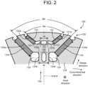
- FIG. 2 is a partial transverse sectional view illustrating the permanent magnets 130 and the rotor core 120 therearound in one magnetic pole of the permanent magnet rotor 100 according to the embodiment.
- the permanent magnet rotor 100 has an even number of magnetic poles 139, and the magnetic poles whose polarities are opposite, that is, the magnetic poles 139 whose magnetic lines of force are in opposite directions are alternately arranged to be adjacent to each other in the circumferential direction.
- FIG. 2 illustrates one of the magnetic poles 139.
- a direction parallel to the extension direction of the axis of the rotor shaft 110, that is, a direction (front-rear direction) perpendicular to FIG. 2 is defined as an axial direction.
- a direction extending away from the rotation axis CL ( FIG. 1 ) of the rotor shaft 110 is defined as a radial direction.
- a direction in which the permanent magnet rotor 100 rotates is defined as a circumferential direction.
- the permanent magnet rotor 100 has, in each of the magnetic poles, the first outer magnet 131, a second outer magnet 132, the first inner magnet 133, and a second inner magnet 134.
- the first outer magnet 131 and the second outer magnet 132 are arranged on the radially outer side of the first inner magnet 133 and the second inner magnet 134.
- the first outer magnet 131 and the second outer magnet 132 are formed to make a pair. Specifically, the first outer magnet 131 and the second outer magnet 132 line up in the circumferential direction, and are arranged such that a gap between the first outer magnet 131 and the second outer magnet 132, that is, their circumferential distance, becomes larger as they go toward the radially outer side.
- FIG. 2 illustrates, as an example, the case where the first outer magnet 131 and the second outer magnet 132 are symmetrical and the first inner magnet 133 and the second inner magnet 134 are symmetrical with respect to the center axis (d-axis) of the magnetic pole 139 in a cross section perpendicular to the axial direction, that is, the case of what is called a V-arrangement, but this is not restrictive, that is, the first outer magnet 131 and the second outer magnet 132 may be different in size, or their directions may be asymmetrical. Similarly, the first inner magnet 133 and the second inner magnet 134 may be different in size, or their directions may be asymmetrical.
- a first outer through hole 121, a second outer through hole 122, a first inner through hole 124, and a second inner through hole 125 for housing the first outer magnet 131, the second outer magnet 132, the first inner magnet 133, and the second inner magnet 134 respectively are formed.
- the first outer through hole 121, the second outer through hole 122, the first inner through hole 124, and the second inner through hole 125 are regions high in magnetic reluctance and each function as a flux barrier.
- the radially inner sides of the first outer through hole 121 and the second outer through hole 122 forming an outer layer are adjacent to each other across two inner center bridges 123 therebetween. Further, the radially outer portions of the first outer through hole 121 and the second outer through hole 122 communicate with a radially outer side of the rotor core 120. That is, there are no top bridges thereof.
- the radially inner sides of the first inner through hole 124 and the second inner through hole 125 forming an inner layer are adjacent to each other across two inner center bridges 126 therebetween. Further, the radially outer portions of the first inner through hole 124 and the second inner through hole 125 communicate with the radially outer side of the rotor core 120. That is, there are no top bridges thereof.
- an angle made by a radially outer wall 121a of the first outer through hole 121 and a radially outer wall 122a of the second outer through hole 122, that is, an opening angle between their radially outward extension directions will be called an outer opening angle ⁇ a.
- an angle made by a radially outer wall 124a of the first inner through hole 124 and a radially outer wall 125a of the second inner through hole 125, that is, an angle between their radially outward extension directions will be called an inner opening angle ⁇ b.
- the outer opening angle ⁇ a is larger than the inner opening angle ⁇ b. That is, the following formula (1) holds. 0 ⁇ ⁇ b ⁇ ⁇ a ⁇ 180 °
- the distance between the first outer through hole 121 and the second outer through hole 122 specifically, the distance between a circumferentially inner wall 121b of the first outer through hole 121 and a circumferentially inner wall 122b of the second outer through hole 122 will be called an inter-outer through hole length xa.
- the distance between the first inner through hole 124 and the second inner through hole 125 specifically, the distance between a circumferentially inner wall 124b of the first inner through hole 124 and a circumferentially inner wall 125b of the second inner through hole 125 will be called an inter-inner through hole length xb.
- FIG. 2 illustrates, as an example, the case where the inter-inner through hole length xb is larger than the inter-outer through hole length xa, that is, the following formula (2) holds. xa ⁇ xb
- the permanent magnet rotor 100 only needs to satisfy the condition that the outer opening angle ⁇ a is larger than the inner opening angle ⁇ b as represented by the above formula (1). That is, the condition that the inter-inner through hole length xb is larger than the inter-outer through hole length xa as represented by the formula (2) is not an essential condition though further improving the effect of this embodiment.
- FIG. 3 is a partial transverse sectional view illustrating the conventional example of the rotor core 120 around the permanent magnets 130 in the single magnetic pole 139 of the permanent magnet rotor according to the embodiment.
- an inner opening angle ⁇ b0 is equal to the outer opening angle ⁇ a.
- an inter-inner through hole length xb0 is equal to the inter-outer through hole length xa.
- This conventional example illustrated in FIG. 3 will be called a base shape.
- FIG. 4 is a partial transverse sectional view illustrating a first example of the rotor core 120 around the permanent magnets 130 in the single magnetic pole 139 of the permanent magnet rotor 100 according to the embodiment.
- the broken line represents the base-shaped one.
- the inner opening angle ⁇ b is smaller than the inner opening angle ⁇ b0 in the conventional example.
- point P1 at which the radially outer wall 124a of the first inner through hole 124 intersects with an opening and point P2 at which the radially outer wall 125a of the second inner through hole 125 intersects with an opening remain at their positions in the conventional example.
- first inner through hole 124 and the second inner through hole 125 have such a shape that the circumferential positions of the circumferentially inner wall 124b of the first inner through hole 124 and the circumferentially inner wall 125b of the second inner through hole 125 are maintained so that the inter-inner through hole length is left equal to the inter-inner through hole length xb0 in the conventional example. Accordingly, their radially inner ends move radially inward according to the change in their inclination.
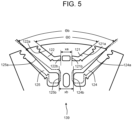
- FIG. 5 is a partial transverse sectional view illustrating a second example of the rotor core 120 around the permanent magnets 130 in the single magnetic pole 139 of the permanent magnet rotor 100 according to the embodiment.
- the contents of the second example are the same as the contents illustrated in FIG. 2 .
- the broken line represents the base-shaped one.
- the inner opening angle ⁇ b is smaller than the inner opening angle ⁇ b0 in the conventional example.
- the second example is the same as the first example in that point P1 at which the radially outer wall 124a of the first inner through hole 124 intersects with the opening and point P2 at which the radially outer wall 125a of the second inner through hole 125 intersects with the opening remain at the positions in the conventional example.
- the first inner through hole 124 and the second inner through hole 125 have such a shape that the inter-inner through hole length xb has a larger value than that of the inter-inner through hole length xb0 in the conventional example.
- FIG. 6 is a graph illustrating the effect of the first and second examples of the rotor core 120 around the permanent magnets 130 in the single magnetic pole 139 of the permanent magnet rotor 100 according to the embodiment.
- the horizontal axis represents cases, and three indexes regarding each case are shown. From the left, the first one is torque.
- the second one is stress A, which is the maximum stress in the outer center bridges 123, and the third one is stress B, which is the maximum stress in the inner center bridges 126.
- the first axis represents torque [P.U.] and the second axis represents stress [P.U.].
- case 1 to case 3 correspond to the permanent magnet rotor 100 according to this embodiment.
- the shape of the conventional example is set as a reference shape (base shape), and values on the vertical axis are based on those in the base shape. Therefore, the values of torque [P.U.] and stresses [P.U.] in the case of the base shape on the horizontal axis are 1.00.
- Case 2 where ⁇ a > ⁇ b and xa ⁇ xb, is a case corresponding to the permanent magnet rotor 100 according to this embodiment.
- case 3 ⁇ a > ⁇ b and xa ⁇ xb as in case 2, but the inclination is made such that the radially outer side fans out more, and it is a case corresponding to the permanent magnet rotor 100 according to the present embodiment.
- the outer center bridges 123 and the inner center bridges 126 each incline with their radially outer sides fanning out in the same manner as in the V-shape arrangement.
- the distance between points closest to the center of the magnetic pole 139, of outer sides of the straight portions in the inner center bridges 126 is larger than the distance between points closest to the center of the magnetic pole 139, of outer sides of the straight portions in the outer center bridges 123.
- second inner through hole 125a...radially outer wall, 125b...circumferentially inner wall, 126... inner center bridge, 130...permanent magnet, 131...first outer magnet, 132... second outer magnet, 133...first inner magnet, 134...second inner magnet, 139...magnetic pole
Landscapes
- Engineering & Computer Science (AREA)
- Power Engineering (AREA)
- Permanent Field Magnets Of Synchronous Machinery (AREA)
Abstract
Description
- Embodiments of the present invention relate to a permanent magnet rotor and a permanent magnet rotary electric machine using the same.
- To achieve a low-carbon/decarbonized society, electrically-powered vehicles such as hybrid electric vehicles (HEV) and electric vehicles (EV) are coming into wide use. As power sources for these, permanent magnet motors are typically used. Because of its excellent variable-speed operation characteristics, a permanent magnet motor having permanent magnets arranged in a two-layered V-shape has been proposed and used in recent years.
- Further, aiming at higher performance of a motor, its speed is becoming higher. In a rotor, bridges are provided to mechanically support centrifugal force acting on a core on the radially outer side of flux barriers and on permanent magnets. Generally, a thick bridge is capable of alleviating stress caused by the centrifugal force. On the other hand, as the bridge is thicker, a leakage magnetic flux increases to lower performance such as torque. Thus, there is a contradictory issue. This necessitates an art to alleviate the stress acting on the bridges without lowering performance.
- To cope with this, there has been proposed a structure for the configuration in which two permanent magnets are arranged to face each other in the circumferential direction with their distance becoming larger as they go more radially outward. In this structure, flux barriers communicate with the radially outer side of a rotor core, that is, there are no top bridges on the radially outer part, and centrifugal force is supported only by a center bridge on the radially inner part. Achieving the support with a structurally advantageous axial force, this method is expected to be capable of alleviating stress while maintaining performance or improving performance while maintaining stress. In the case where the permanent magnets facing each other are the same and are symmetrical with respect to the d-axis which is the center axis of the magnetic pole, this is usually called a V-arrangement.
-
- Patent Document 1: International Publication No.
2018/190103 - Patent Document 2:
Japanese Patent Application Laid-open No. 2020-14322 - Patent Document 3: International Publication No.
2018/051690 - Patent Document 4: International Publication No.
2015/156353 - As a configuration in which a plurality of layers, for example, two layers of a set of two permanent magnets facing each other in the circumferential direction are arranged in the radial direction, the following proposals have been made as will be described next.
- A first example describes a bridge width for achieving both a reduction in a leakage magnetic flux and mechanical strength of bridges, in a configuration in which flux barriers each have a top bridge and have, on a radially inner side, two center bridges.
- A second example describes that, in a configuration in which all the flux barriers have top bridges, and circumferentially inner flux barriers have two center bridges, by arranging the bridges of the flux barriers such that they are not aligned on a straight line, it is possible to reduce a leakage magnetic flux while maintaining mechanical strength.
- As described above, in a rotor having top bridges and a plurality of flux barriers, it has conventionally been known that an index for selecting an appropriate bridge width for achieving both performance and strength or the non-alignment of the center bridges in the flux barriers on a straight line is necessary. In other words, if an appropriate bridge width is selected and the center bridges are arranged such that they are not aligned on a straight line, performance and mechanical strength are both achieved regardless of how the bridges are arranged.
- On the other hand, in a rotor in which a plurality of flux barriers with no top bridges are adjacent to each other, since radially outer sides of a core in between are not restricted, these parts of the core noticeably deform, necessitating a measure for the new problem.
- Now, let us consider, as a region of interest, a part (layer) of a rotor core where flux barriers housing two permanent magnets at positions facing each other have no top bridges but have openings, and two center bridges connect a radially outer part of the fan shape and the core portion on the radially inner part thereof. In this case, the center bridge on the radially inner part needs to have a larger supporting force, and thus its straight portion is thicker than that of the center bridge on the radially outer side, and at a corner portion at its root, a large arc is formed. In the case where the layers without the top bridges are adjacent, the core between the layers has a cantilever structure with the center bridges being a fixed end because the radially outer sides of the core portion sandwiched by the magnets are not restricted. Therefore, it is necessary to reduce bending stress acting on the roots of the bridges without lowing torque performance.
- An object of the present invention is to provide a permanent magnet rotor that achieves a reduction in bending stress acting on roots of bridges without lowing torque performance.
- To attain the above object, a permanent magnet rotor according to an embodiment of the present invention includes: a rotor shaft extending in a rotation axis direction; a rotor core attached to the rotor shaft, and having, in each magnetic pole, a first outer through hole and a second outer through hole that are formed on a radially outer side to make a pair and a first inner through hole and a second inner through hole that are formed on a more radially inner side than the first outer through hole and the second outer through hole to make a pair; a first outer magnet and a second outer magnet housed in the first outer through hole and the second outer through hole respectively; and a first inner magnet and a second inner magnet housed in the first inner through hole and the second inner through hole respectively, wherein an outer opening angle between radially outward extension directions of a radially outer wall of the first outer through hole and a radially outer wall of the second outer through hole is larger than an inner opening angle between radially outward extension directions of a radially outer wall of the first inner through hole and a radially outer wall of the second inner through hole, and wherein an inter-inner through hole length between the first inner through hole and the second inner through hole is larger than an inter-outer through hole length between the first outer through hole and the second outer through hole.
-
-
FIG. 1 is a sectional longitudinal view illustrating a configuration example of a permanent magnet rotary electric machine having a permanent magnet rotor according to an embodiment. -
FIG. 2 is a partial transverse sectional view illustrating permanent magnets and a rotor core therearound in one magnetic pole of the permanent magnet rotor according to the embodiment. -
FIG. 3 is a partial transverse sectional view illustrating a conventional example of the rotor core around the permanent magnets in one magnetic pole of the permanent magnet rotor according to the embodiment. -
FIG. 4 is a partial transverse sectional view illustrating a first example of the rotor core around the permanent magnets in one magnetic pole of the permanent magnet rotor according to the embodiment. -
FIG. 5 is a partial transverse sectional view illustrating a second example of the rotor core around the permanent magnets in one magnetic pole of the permanent magnet rotor according to the embodiment. -
FIG. 6 is a graph illustrating the effect of the first and second examples of the rotor core around the permanent magnets in one magnetic pole of the permanent magnet rotor according to the embodiment. - A permanent magnet rotor and a permanent magnet rotary electric machine according to an embodiment of the present invention will be hereinafter described with reference to the drawings. Here, parts that are identical or similar to each other are denoted by common reference signs and a redundant description thereof will be omitted.
-
FIG. 1 is a sectional longitudinal view illustrating a configuration example of the permanent magnet rotaryelectric machine 1 having thepermanent magnet rotor 100 according to the embodiment. - The permanent magnet rotary
electric machine 1 has thepermanent magnet rotor 100, astator 10, twobearings 20, twobearing brackets 30, and aframe 40. - The
permanent magnet rotor 100 has arotor shaft 110 extending in a direction of a rotation axis CL, arotor core 120 attached to a radially outer side of therotor shaft 110, andpermanent magnets 130 embedded in therotor core 120. InFIG. 1 , a firstouter magnet 131 and a firstinner magnet 133 out of thepermanent magnets 130 are illustrated, but details will be described later with reference toFIG. 2 . - The
stator 10 has acylindrical stator core 11 arranged on the outer side of the outer peripheral surface of therotor core 120 to surround therotor core 120 and a stator winding 12 wound around thestator core 11. - The two
bearings 20 rotatably support the rotor shaft. Each of the twobearing brackets 30 statically support each of the twobearings 20. Theframe 40 has a cylindrical shape, houses thestator 10, and has ends connected to the twobearing brackets 30 respectively to support these. -
FIG. 2 is a partial transverse sectional view illustrating thepermanent magnets 130 and therotor core 120 therearound in one magnetic pole of thepermanent magnet rotor 100 according to the embodiment. - The
permanent magnet rotor 100 has an even number ofmagnetic poles 139, and the magnetic poles whose polarities are opposite, that is, themagnetic poles 139 whose magnetic lines of force are in opposite directions are alternately arranged to be adjacent to each other in the circumferential direction.FIG. 2 illustrates one of themagnetic poles 139. - Here, for convenience of the description, directions will be defined. A direction parallel to the extension direction of the axis of the
rotor shaft 110, that is, a direction (front-rear direction) perpendicular toFIG. 2 is defined as an axial direction. A direction extending away from the rotation axis CL (FIG. 1 ) of therotor shaft 110 is defined as a radial direction. A direction in which thepermanent magnet rotor 100 rotates is defined as a circumferential direction. - The
permanent magnet rotor 100 according to this embodiment has, in each of the magnetic poles, the firstouter magnet 131, a secondouter magnet 132, the firstinner magnet 133, and a secondinner magnet 134. The firstouter magnet 131 and the secondouter magnet 132 are arranged on the radially outer side of the firstinner magnet 133 and the secondinner magnet 134. - The first
outer magnet 131 and the secondouter magnet 132 are formed to make a pair. Specifically, the firstouter magnet 131 and the secondouter magnet 132 line up in the circumferential direction, and are arranged such that a gap between the firstouter magnet 131 and the secondouter magnet 132, that is, their circumferential distance, becomes larger as they go toward the radially outer side. -
FIG. 2 illustrates, as an example, the case where the firstouter magnet 131 and the secondouter magnet 132 are symmetrical and the firstinner magnet 133 and the secondinner magnet 134 are symmetrical with respect to the center axis (d-axis) of themagnetic pole 139 in a cross section perpendicular to the axial direction, that is, the case of what is called a V-arrangement, but this is not restrictive, that is, the firstouter magnet 131 and the secondouter magnet 132 may be different in size, or their directions may be asymmetrical. Similarly, the firstinner magnet 133 and the secondinner magnet 134 may be different in size, or their directions may be asymmetrical. - In the
rotor core 120, a first outer throughhole 121, a second outer throughhole 122, a first inner throughhole 124, and a second inner throughhole 125 for housing the firstouter magnet 131, the secondouter magnet 132, the firstinner magnet 133, and the secondinner magnet 134 respectively are formed. The first outer throughhole 121, the second outer throughhole 122, the first inner throughhole 124, and the second inner throughhole 125 are regions high in magnetic reluctance and each function as a flux barrier. - The radially inner sides of the first outer through
hole 121 and the second outer throughhole 122 forming an outer layer are adjacent to each other across two inner center bridges 123 therebetween. Further, the radially outer portions of the first outer throughhole 121 and the second outer throughhole 122 communicate with a radially outer side of therotor core 120. That is, there are no top bridges thereof. - The radially inner sides of the first inner through
hole 124 and the second inner throughhole 125 forming an inner layer are adjacent to each other across twoinner center bridges 126 therebetween. Further, the radially outer portions of the first inner throughhole 124 and the second inner throughhole 125 communicate with the radially outer side of therotor core 120. That is, there are no top bridges thereof. - Here, an angle made by a radially
outer wall 121a of the first outer throughhole 121 and a radiallyouter wall 122a of the second outer throughhole 122, that is, an opening angle between their radially outward extension directions will be called an outer opening angle Θa. Similarly, an angle made by a radiallyouter wall 124a of the first inner throughhole 124 and a radiallyouter wall 125a of the second inner throughhole 125, that is, an angle between their radially outward extension directions will be called an inner opening angle Θb. - In this embodiment, the outer opening angle Θa is larger than the inner opening angle Θb. That is, the following formula (1) holds.

- Further, the distance between the first outer through
hole 121 and the second outer throughhole 122, specifically, the distance between a circumferentiallyinner wall 121b of the first outer throughhole 121 and a circumferentiallyinner wall 122b of the second outer throughhole 122 will be called an inter-outer through hole length xa. Similarly, the distance between the first inner throughhole 124 and the second inner throughhole 125, specifically, the distance between a circumferentiallyinner wall 124b of the first inner throughhole 124 and a circumferentiallyinner wall 125b of the second inner throughhole 125 will be called an inter-inner through hole length xb. -
FIG. 2 illustrates, as an example, the case where the inter-inner through hole length xb is larger than the inter-outer through hole length xa, that is, the following formula (2) holds.
- It should be noted that the
permanent magnet rotor 100 according to this embodiment only needs to satisfy the condition that the outer opening angle Θa is larger than the inner opening angle Θb as represented by the above formula (1). That is, the condition that the inter-inner through hole length xb is larger than the inter-outer through hole length xa as represented by the formula (2) is not an essential condition though further improving the effect of this embodiment. - Next, the effect of the
permanent magnet rotor 100 according to this embodiment will be described based on comparison with a conventional example. -
FIG. 3 is a partial transverse sectional view illustrating the conventional example of therotor core 120 around thepermanent magnets 130 in the singlemagnetic pole 139 of the permanent magnet rotor according to the embodiment. - In the conventional example illustrated in
FIG. 3 , an inner opening angle Θb0 is equal to the outer opening angle Θa. Further, an inter-inner through hole length xb0 is equal to the inter-outer through hole length xa. This conventional example illustrated inFIG. 3 will be called a base shape. -
FIG. 4 is a partial transverse sectional view illustrating a first example of therotor core 120 around thepermanent magnets 130 in the singlemagnetic pole 139 of thepermanent magnet rotor 100 according to the embodiment. The broken line represents the base-shaped one. - In the first example, the inner opening angle Θb is smaller than the inner opening angle Θb0 in the conventional example.
- In this first example, point P1 at which the radially
outer wall 124a of the first inner throughhole 124 intersects with an opening and point P2 at which the radiallyouter wall 125a of the second inner throughhole 125 intersects with an opening remain at their positions in the conventional example. - Further, the first inner through
hole 124 and the second inner throughhole 125 have such a shape that the circumferential positions of the circumferentiallyinner wall 124b of the first inner throughhole 124 and the circumferentiallyinner wall 125b of the second inner throughhole 125 are maintained so that the inter-inner through hole length is left equal to the inter-inner through hole length xb0 in the conventional example. Accordingly, their radially inner ends move radially inward according to the change in their inclination. -
FIG. 5 is a partial transverse sectional view illustrating a second example of therotor core 120 around thepermanent magnets 130 in the singlemagnetic pole 139 of thepermanent magnet rotor 100 according to the embodiment. The contents of the second example are the same as the contents illustrated inFIG. 2 . Note that the broken line represents the base-shaped one. - In this second example as well, the inner opening angle Θb is smaller than the inner opening angle Θb0 in the conventional example. The second example is the same as the first example in that point P1 at which the radially
outer wall 124a of the first inner throughhole 124 intersects with the opening and point P2 at which the radiallyouter wall 125a of the second inner throughhole 125 intersects with the opening remain at the positions in the conventional example. - On the other hand, the first inner through
hole 124 and the second inner throughhole 125 have such a shape that the inter-inner through hole length xb has a larger value than that of the inter-inner through hole length xb0 in the conventional example. -
FIG. 6 is a graph illustrating the effect of the first and second examples of therotor core 120 around thepermanent magnets 130 in the singlemagnetic pole 139 of thepermanent magnet rotor 100 according to the embodiment. The horizontal axis represents cases, and three indexes regarding each case are shown. From the left, the first one is torque. The second one is stress A, which is the maximum stress in the outer center bridges 123, and the third one is stress B, which is the maximum stress in the inner center bridges 126. Further, as for the vertical axis, the first axis represents torque [P.U.] and the second axis represents stress [P.U.]. - Hereinafter, the cases on the horizontal axis will be sequentially described. Note that
case 1 tocase 3 correspond to thepermanent magnet rotor 100 according to this embodiment. - The shape of the conventional example is set as a reference shape (base shape), and values on the vertical axis are based on those in the base shape. Therefore, the values of torque [P.U.] and stresses [P.U.] in the case of the base shape on the horizontal axis are 1.00.
-
Case 1, where Θa > Θb and xa = xb, is a case corresponding to thepermanent magnet rotor 100 according to this embodiment. - In
case 1, torque slightly increases, and stress A and stress B both decrease. -
Case 2, where Θa > Θb and xa < xb, is a case corresponding to thepermanent magnet rotor 100 according to this embodiment. - In
case 2, stress A decreases more than incase 1. - In
case 3, Θa > Θb and xa < xb as incase 2, but the inclination is made such that the radially outer side fans out more, and it is a case corresponding to thepermanent magnet rotor 100 according to the present embodiment. In more detail, the outer center bridges 123 and the inner center bridges 126 each incline with their radially outer sides fanning out in the same manner as in the V-shape arrangement. The distance between points closest to the center of themagnetic pole 139, of outer sides of the straight portions in the inner center bridges 126 is larger than the distance between points closest to the center of themagnetic pole 139, of outer sides of the straight portions in the outer center bridges 123. - In
case 3, stress A and stress B both decrease more than incase 2. - As shown by the
above case 1 tocase 3, in thepermanent magnet rotor 100 according to this embodiment, as compared with the conventional example shown as the base shape, torque increases, and stress A and stress B both decrease. - Note that the above effect is achieved also in the case where a top bridge is present for each of the first outer through
hole 121 and the second outer throughhole 122, the first inner throughhole 124 and the second inner throughhole 125. - According to the embodiments described hitherto, it is possible to provide a permanent magnet rotor that enables a reduction in bending stress acting on the roots of bridges without lowering torque performance.
- While certain embodiments have been described, these embodiments have been presented by way of example only, and are not intended to limit the scope of the inventions. Further, the features of the embodiments may be combined. The embodiments described herein may be embodied in a variety of other forms; furthermore, various omissions, substitutions and changes in the form of the embodiments described herein may be made without departing from the spirit of the inventions. The accompanying claims and their equivalents are intended to cover such forms or modifications as would fall within the scope and spirit of the inventions.
- 1... permanent magnet rotary electric machine, 10... stator, 11... stator core, 12... stator winding, 20...bearing, 30...bearing bracket, 40...frame, 100...permanent magnet rotor, 110...rotor shaft, 120...rotor core, 121...first outer through hole, 121a...radially outer wall, 121b...circumferentially inner wall, 122... second outer through hole, 122a...radially outer wall, 122b...circumferentially inner wall, 123...outer center bridge, 124...first inner through hole, 124a...radially outer wall, 124b ... circumferentially inner wall, 125... second inner through hole, 125a...radially outer wall, 125b...circumferentially inner wall, 126... inner center bridge, 130...permanent magnet, 131...first outer magnet, 132... second outer magnet, 133...first inner magnet, 134...second inner magnet, 139...magnetic pole
Claims (5)
- A permanent magnet rotor (100) comprising:a rotor shaft (110) extending in a rotation axis direction;a rotor core (120) attached to the rotor shaft (110), and having, in each magnetic pole (139), a first outer through hole (121) and a second outer through hole (122) that are formed on a radially outer side to make a pair and a first inner through hole (124) and a second inner through hole (125) that are formed on a more radially inner side than the first outer through hole (121) and the second outer through hole (122) to make a pair;a first outer magnet (131) and a second outer magnet (132) housed in the first outer through hole (121) and the second outer through hole (122) respectively; anda first inner magnet (133) and a second inner magnet (134) housed in the first inner through hole (124) and the second inner through hole (125) respectively,wherein an outer opening angle between radially outward extension directions of a radially outer wall (121a) of the first outer through hole (121) and a radially outer wall (122a) of the second outer through hole (122) is larger than an inner opening angle between radially outward extension directions of a radially outer wall (124a) of the first inner through hole (124) and a radially outer wall (125a) of the second inner through hole (125), andwherein an inter-inner through hole length between the first inner through hole (124) and the second inner through hole (125) is larger than an inter-outer through hole length between the first outer through hole (121) and the second outer through hole (122).
- The permanent magnet rotor according to claim 1, wherein the first outer through hole (121) and the second outer through hole (122) are adjacent to each other across two inner center bridges (123) therebetween,wherein of the first inner through hole (124) and the second inner through hole (125) are adjacent to each other across two inner center bridges (126) therebetween, andwherein the outer center bridges (123) and the inner center bridges (126) each incline with their radially outer sides fanning out.
- The permanent magnet rotor (100) according to claim 1, wherein the first outer through hole (121) and the second outer through hole (122), and the first inner through hole (124) and the second inner through hole (125) communicate with a radially outer side of the rotor core (120).
- The permanent magnet rotor (100) according to claim 1, wherein with respect to a d-axis which is a center of the magnetic pole (139), the first inner through hole (124) and the second inner through hole (125) are symmetrical and the first outer through hole (121) and the second outer through hole (122) are symmetrical.
- A permanent magnet rotary electric machine comprising:The permanent magnet rotor (100) according to any one of claim 1 to claim 4;a stator (10) having a stator core (11) in a cylindrical shape arranged on a radially outer side of the rotor core (120) and a stator winding (12) wound around the stator core (11);two bearings (20) to rotatably support two sides of the rotor shaft (110) in terms of the rotation axis direction;two bearing brackets (30) to statically support the two bearings (20) respectively; anda frame (40) arranged to cover a radially outer side of the stator (10) and to support the two bearing brackets (30).
Applications Claiming Priority (2)
| Application Number | Priority Date | Filing Date | Title |
|---|---|---|---|
| JP2022127926 | 2022-08-10 | ||
| PCT/JP2022/038529 WO2024034149A1 (en) | 2022-08-10 | 2022-10-17 | Permanent magnet rotor and permanent magnet rotary electric machine |
Publications (2)
| Publication Number | Publication Date |
|---|---|
| EP4572094A1 true EP4572094A1 (en) | 2025-06-18 |
| EP4572094A4 EP4572094A4 (en) | 2025-11-19 |
Family
ID=89845539
Family Applications (1)
| Application Number | Title | Priority Date | Filing Date |
|---|---|---|---|
| EP22930138.7A Withdrawn EP4572094A4 (en) | 2022-08-10 | 2022-10-17 | PERMANENT MAGNET ROTOR AND ELECTRIC PERMANENT MAGNET LATHE |
Country Status (4)
| Country | Link |
|---|---|
| US (1) | US20240055918A1 (en) |
| EP (1) | EP4572094A4 (en) |
| JP (1) | JPWO2024034149A1 (en) |
| CN (1) | CN117882273A (en) |
Family Cites Families (10)
| Publication number | Priority date | Publication date | Assignee | Title |
|---|---|---|---|---|
| JP5659031B2 (en) * | 2011-02-02 | 2015-01-28 | 株式会社東芝 | Permanent magnet rotating electric machine |
| JP5643127B2 (en) * | 2011-02-03 | 2014-12-17 | トヨタ自動車株式会社 | Rotating machine rotor |
| JP5480176B2 (en) * | 2011-02-03 | 2014-04-23 | アイシン・エィ・ダブリュ株式会社 | Rotating machine rotor |
| JP5370433B2 (en) * | 2011-08-21 | 2013-12-18 | 株式会社豊田自動織機 | Permanent magnet embedded electric motor |
| JP6508168B2 (en) * | 2016-11-15 | 2019-05-08 | トヨタ自動車株式会社 | Electric rotating machine |
| WO2019026979A1 (en) * | 2017-08-01 | 2019-02-07 | 株式会社デンソー | Rotary electric machine, rotary electric machine drive system, magnet, method for manufacturing magnet, magnetization device, and magnet unit |
| JP6879140B2 (en) * | 2017-09-15 | 2021-06-02 | トヨタ自動車株式会社 | Rotating machine |
| JP6989458B2 (en) * | 2018-08-03 | 2022-01-05 | 株式会社東芝 | Rotor of rotary electric machine |
| JP7107243B2 (en) * | 2019-02-12 | 2022-07-27 | トヨタ自動車株式会社 | Rotating electric machine |
| CN113994569B (en) * | 2019-09-24 | 2024-07-30 | 株式会社东芝 | Rotor of rotating electrical machine |
-
2022
- 2022-10-17 CN CN202280009181.7A patent/CN117882273A/en not_active Withdrawn
- 2022-10-17 JP JP2023520294A patent/JPWO2024034149A1/ja active Pending
- 2022-10-17 EP EP22930138.7A patent/EP4572094A4/en not_active Withdrawn
-
2023
- 2023-09-25 US US18/473,491 patent/US20240055918A1/en active Pending
Also Published As
| Publication number | Publication date |
|---|---|
| EP4572094A4 (en) | 2025-11-19 |
| CN117882273A (en) | 2024-04-12 |
| US20240055918A1 (en) | 2024-02-15 |
| JPWO2024034149A1 (en) | 2024-02-15 |
Similar Documents
| Publication | Publication Date | Title |
|---|---|---|
| US10644550B2 (en) | Rotor for rotating electric machine | |
| EP2015425B1 (en) | Permanent magnet rotating electrical machine and permanent magnet rotating electrical machine system | |
| US10491065B2 (en) | Permanent magnet synchronous motor | |
| JP7758062B2 (en) | Rotor of an electric rotating machine and electric rotating machine including said rotor | |
| US12283848B2 (en) | Rotor for rotary electric machine | |
| EP4220899A1 (en) | Rotor core | |
| WO2018021939A1 (en) | Synchronous reluctance machine | |
| JP2021136785A (en) | Rotor of rotary electric machine and rotary electric machine | |
| US20240055918A1 (en) | Permanent magnet rotor and permanent magnet rotary electric machine | |
| CN102377307B (en) | Rotating electric machine and manufacturing method thereof | |
| US20230223805A1 (en) | Rotor and rotary electric machine | |
| WO2024034149A1 (en) | Permanent magnet rotor and permanent magnet rotary electric machine | |
| JP7455994B2 (en) | rotating electric machine | |
| EP4492640A1 (en) | Rotor and ipm motor using same | |
| CN117674474A (en) | Rotary electric machine | |
| JP7754257B1 (en) | Electric motors and compressors | |
| CN116458033A (en) | Rotor of a rotating electrical machine | |
| US20250070605A1 (en) | Rotor for rotating electrical machine | |
| US20230223804A1 (en) | Rotor and rotary electric machine | |
| EP4518102A1 (en) | Interior permanent magnet rotor and rotating electric machine | |
| EP4614766A1 (en) | Two-layer magnet-embedded rotor, two-layer magnet-embedded rotary electric machine, and method for manufacturing two-layer magnet-embedded rotor | |
| JP2026061815A (en) | Electric motors and compressors | |
| US20240014700A1 (en) | Rotary electric machine | |
| JP2026061964A (en) | Rotor, electric motor, and compressor | |
| JP2024143202A (en) | Electric motor |
Legal Events
| Date | Code | Title | Description |
|---|---|---|---|
| STAA | Information on the status of an ep patent application or granted ep patent |
Free format text: STATUS: UNKNOWN |
|
| STAA | Information on the status of an ep patent application or granted ep patent |
Free format text: STATUS: THE INTERNATIONAL PUBLICATION HAS BEEN MADE |
|
| PUAI | Public reference made under article 153(3) epc to a published international application that has entered the european phase |
Free format text: ORIGINAL CODE: 0009012 |
|
| STAA | Information on the status of an ep patent application or granted ep patent |
Free format text: STATUS: REQUEST FOR EXAMINATION WAS MADE |
|
| 17P | Request for examination filed |
Effective date: 20230913 |
|
| AK | Designated contracting states |
Kind code of ref document: A1 Designated state(s): AL AT BE BG CH CY CZ DE DK EE ES FI FR GB GR HR HU IE IS IT LI LT LU LV MC ME MK MT NL NO PL PT RO RS SE SI SK SM TR |
|
| RAP1 | Party data changed (applicant data changed or rights of an application transferred) |
Owner name: KABUSHIKI KAISHA TOSHIBA |
|
| STAA | Information on the status of an ep patent application or granted ep patent |
Free format text: STATUS: THE APPLICATION HAS BEEN WITHDRAWN |
|
| A4 | Supplementary search report drawn up and despatched |
Effective date: 20251022 |
|
| DAV | Request for validation of the european patent (deleted) | ||
| DAX | Request for extension of the european patent (deleted) | ||
| RIC1 | Information provided on ipc code assigned before grant |
Ipc: H02K 1/276 20220101AFI20251016BHEP |
|
| 18W | Application withdrawn |
Effective date: 20251111 |