EP4572091A1 - Synchronmotor mit mindestens einem stator und einem rotor mit einem rotorpermanentmagneten, verfahren zur herstellung eines rotorpermanentmagneten eines rotors für einen synchronmotor - Google Patents
Synchronmotor mit mindestens einem stator und einem rotor mit einem rotorpermanentmagneten, verfahren zur herstellung eines rotorpermanentmagneten eines rotors für einen synchronmotor Download PDFInfo
- Publication number
- EP4572091A1 EP4572091A1 EP23307174.5A EP23307174A EP4572091A1 EP 4572091 A1 EP4572091 A1 EP 4572091A1 EP 23307174 A EP23307174 A EP 23307174A EP 4572091 A1 EP4572091 A1 EP 4572091A1
- Authority
- EP
- European Patent Office
- Prior art keywords
- permanent magnet
- hard magnetic
- rotor
- magnetic material
- magnet element
- Prior art date
- Legal status (The legal status is an assumption and is not a legal conclusion. Google has not performed a legal analysis and makes no representation as to the accuracy of the status listed.)
- Pending
Links
Images


Classifications
-
- H—ELECTRICITY
- H02—GENERATION; CONVERSION OR DISTRIBUTION OF ELECTRIC POWER
- H02K—DYNAMO-ELECTRIC MACHINES
- H02K1/00—Details of the magnetic circuit
- H02K1/06—Details of the magnetic circuit characterised by the shape, form or construction
- H02K1/22—Rotating parts of the magnetic circuit
- H02K1/27—Rotor cores with permanent magnets
- H02K1/2706—Inner rotors
-
- H—ELECTRICITY
- H01—ELECTRIC ELEMENTS
- H01F—MAGNETS; INDUCTANCES; TRANSFORMERS; SELECTION OF MATERIALS FOR THEIR MAGNETIC PROPERTIES
- H01F7/00—Magnets
- H01F7/02—Permanent magnets [PM]
-
- H—ELECTRICITY
- H02—GENERATION; CONVERSION OR DISTRIBUTION OF ELECTRIC POWER
- H02K—DYNAMO-ELECTRIC MACHINES
- H02K1/00—Details of the magnetic circuit
- H02K1/02—Details of the magnetic circuit characterised by the magnetic material
-
- H—ELECTRICITY
- H02—GENERATION; CONVERSION OR DISTRIBUTION OF ELECTRIC POWER
- H02K—DYNAMO-ELECTRIC MACHINES
- H02K1/00—Details of the magnetic circuit
- H02K1/06—Details of the magnetic circuit characterised by the shape, form or construction
- H02K1/12—Stationary parts of the magnetic circuit
- H02K1/14—Stator cores with salient poles
- H02K1/141—Stator cores with salient poles consisting of C-shaped cores
- H02K1/143—Stator cores with salient poles consisting of C-shaped cores of the horse-shoe type
-
- H—ELECTRICITY
- H02—GENERATION; CONVERSION OR DISTRIBUTION OF ELECTRIC POWER
- H02K—DYNAMO-ELECTRIC MACHINES
- H02K1/00—Details of the magnetic circuit
- H02K1/06—Details of the magnetic circuit characterised by the shape, form or construction
- H02K1/22—Rotating parts of the magnetic circuit
- H02K1/27—Rotor cores with permanent magnets
-
- H—ELECTRICITY
- H02—GENERATION; CONVERSION OR DISTRIBUTION OF ELECTRIC POWER
- H02K—DYNAMO-ELECTRIC MACHINES
- H02K15/00—Processes or apparatus specially adapted for manufacturing, assembling, maintaining or repairing of dynamo-electric machines
- H02K15/02—Processes or apparatus specially adapted for manufacturing, assembling, maintaining or repairing of dynamo-electric machines of stator or rotor bodies
- H02K15/03—Processes or apparatus specially adapted for manufacturing, assembling, maintaining or repairing of dynamo-electric machines of stator or rotor bodies having permanent magnets
-
- H—ELECTRICITY
- H02—GENERATION; CONVERSION OR DISTRIBUTION OF ELECTRIC POWER
- H02K—DYNAMO-ELECTRIC MACHINES
- H02K21/00—Synchronous motors having permanent magnets; Synchronous generators having permanent magnets
- H02K21/12—Synchronous motors having permanent magnets; Synchronous generators having permanent magnets with stationary armatures and rotating magnets
- H02K21/14—Synchronous motors having permanent magnets; Synchronous generators having permanent magnets with stationary armatures and rotating magnets with magnets rotating within the armatures
- H02K21/18—Synchronous motors having permanent magnets; Synchronous generators having permanent magnets with stationary armatures and rotating magnets with magnets rotating within the armatures having horse-shoe armature cores
Definitions
- the present invention relates to a synchronous motor comprising at least one stator and a rotor, the rotor comprising a rotor permanent magnet.
- the present invention relates to a pump comprising a synchronous motor according to the present invention.
- the present invention relates to a method for manufacturing a rotor permanent magnet of a rotor for a synchronous motor according to the present invention.
- Synchronous motors are well known and are nowadays used in particular as drives, e.g., for pumps, especially water pumps.
- Such motors often comprise rotating rotors that have a metallic shaft and comprise a rotor permanent magnet, typically mounted on the shaft; such rotors typically deliver a torque to drive an actuator like, e.g., a pump unit).
- Such rotors, having a metallic shaft and comprising a rotor permanent magnet are typically arranged such that the rotor permanent magnet that is arranged around the metallic shaft such as to interact - in the assembled electric motor - with the corresponding stator arrangement, wherein such a rotor permanent magnet, being arranged around the metallic shaft, comprises at least one permanent magnet element.
- such rotor permanent magnets typically comprise - at least in part, or, regarding certain areas thereof, e.g., embedded therein - one or a plurality of permanent magnet elements, wherein such one or a plurality of permanent magnet elements are typically made of a hard magnetic material (i.e. having a comparatively high remanence or magnetic remanence).
- a hard magnetic material i.e. having a comparatively high remanence or magnetic remanence
- certain hard magnetic materials - such as, e.g., rare earths hard magnetic materials, typically having a higher magnetic coercivity, compared, e.g. to ferrites - are more sensitive, especially with regard to corrosion, if exposed to water and/or humidity, other hard magnetic materials, e.g.
- ferrites are less sensitive to water contact (or stable in water); however, such less sensitive hard magnetic materials, typically, have a lower magnetic remanence.
- electric motors used for, e.g., water pumps - to use rotors that have a rotor permanent magnet with at least one permanent magnet element in a manner such that,
- An object of the present invention is to provide a technically simple, effective and cost-effective solution for providing a rotor for a synchronous motor, wherein the rotor comprises, besides a shaft element, a rotor permanent magnet that is configured such that it has a comparatively elevated electro-magnetic performance and especially does not necessarily require a watertight enclosure of a high magnetic remanence-hard magnetic material that needs to be shielded from water and/or humidity.
- a further object of the present invention is to provide a corresponding pump comprising a synchronous motor according to the present invention, especially for hydraulic systems and especially for pumping water, as well as to provide a corresponding method for manufacturing a rotor permanent magnet of a rotor for a synchronous motor.
- a synchronous motor comprising at least one stator and a rotor, the rotor comprising a rotor permanent magnet, characterized in that the rotor comprises - besides the rotor permanent magnet - a shaft element, wherein the rotor permanent magnet comprises, or consists of, a first permanent magnet element as well as a second permanent magnet element, wherein the first permanent magnet element mainly comprises, or consists of, a first hard magnetic material and wherein the second permanent magnet element mainly comprises, or consists of, a second hard magnetic material.
- such a rotor permanent magnet is able to be used in a single-phase (or more than single-phase) synchronous motor that comprises, e.g., at least one stator winding, e.g., a U-shaped laminated stator core with, e.g., two poles.
- the rotor is arranged between the poles and comprises the rotor permanent magnet.
- the first and second permanent magnet element in two different steps, e.g. with the first permanent magnet element being realized as an inner core, and the second permanent magnet element being realized as an outer core.
- both the first hard magnetic material and the second hard magnetic material are moldable materials.
- the rotor permanent magnet (or, the rotor besides the shaft element) by means of injection molding of the first hard magnetic material and the second hard magnetic material, especially by means of overmolding the second hard magnetic material onto the first hard magnetic material, i.e. overmolding the second permanent magnet element onto the first permanent magnet element.
- the first and second hard magnetic materials are located axially adjacent (to one another) along a part of the shaft element and parallel to the rotor axis of rotation, wherein especially the radial extension of both the first and the second hard magnetic materials is essentially identical.
- the first hard magnetic material is exclusively located, with regard to the rotor axis of rotation, in a radially inner area of the rotor permanent magnet and wherein the second hard magnetic material is mainly located, with regard to the rotor axis of rotation, in a radially outer area of the rotor permanent magnet.
- the second hard magnetic material i.e. the second permanent magnet element
- the first hard magnetic material i.e. the first permanent magnet element
- the present invention it is advantageously possible and preferred that - along a radially outer surface of the first hard magnetic material - the second hard magnetic material is radially adjacent to the first hard magnetic material.
- the first permanent magnet element is shaped essentially cylindrically, especially around an outer cylindrical or essentially cylindrical surface of the shaft element, in an area of and/or around the shaft element corresponding to a first maximum radius
- the second permanent magnet element is shaped cylindrically, especially around an outer essentially cylindrical or essentially cylindrical surface of the first permanent magnet element, in an area around the first permanent magnet element corresponding to a second maximum radius.
- the first and second hard magnetic materials i.e. the first and second permanent magnet elements
- the first and second hard magnetic materials are realized as concentrical, more or less cylinder-shaped, elements.
- both the first permanent magnet element and the second permanent magnet element extend along a certain length parallel to the rotor axis of rotation, this length especially being inferior to the length of the shaft element.
- the first permanent magnet element is shaped essentially cylindrically, especially around an outer cylindrical or essentially cylindrical surface of the shaft element, in an area of and/or around the shaft element corresponding to a first maximum radius, wherein, axially, the first permanent magnet element extends along a certain length parallel to the rotor axis of rotation, and wherein the second permanent magnet element extends, parallel to the rotor axis of rotation, along a total length of extension of the second permanent magnet element, wherein
- the first permanent magnet element corresponds, at least roughly and assuming a cylindrical outer surface of the shaft element, to a cylindrical shell (having an outer shell diameter of twice the first maximum radius) and the second permanent magnet element corresponds, at least roughly and assuming a cylindrical outer surface of the first permanent magnet element, to a cylindrical shell (having an outer shell diameter of twice the second maximum radius).
- first and/or second permanent magnet element and/or hard magnetic material are shaped differently than just cylindrically (i.e.
- a cylindrical shape meaning to have a respective (radially) outer surface that is radially equally distanced from the axis of rotation of the rotor), especially by means of the (radially) outer surface of the first and/or second permanent magnet element and/or hard magnetic material being varyingly distanced from the axis of rotation of the rotor, e.g. in an undulated manner or varying around or along the circumference of the rotor permanent magnet.
- Rare earth magnetic materials usually used for their magnetic properties are typically sensitive to corrosion when placed in contact with water.
- the second hard magnetic material e.g. a hard ferrite material
- completely surrounding the first hard magnetic material e.g.
- the rare earth magnetic material is protected by the injection molded ferrite layer, and it is advantageously possible that both materials - i.e. the whole rotor volume - contribute to the rotor magnetic properties.
- the inner injected layer(s), i.e. the first permanent magnet element typically includes rare earth metals, such as NdFeB or SmFeN (injection molded in isotropic or anisotropic manner), while the outer layer, i.e. the second permanent magnet element, typically includes, or consists of, injection molded ferrite, especially to be stable in water.
- the first hard magnetic material is a moldable material comprising, or consisting of, a first hard magnetic component and a molding component
- the second hard magnetic material is a moldable material comprising, or consisting of, a second hard magnetic component and a further molding component
- the first hard magnetic material in the form of a mixture comprising, or consisting of, the first hard magnetic component and the molding component.
- the first hard magnetic component is itself the part of the first hard magnetic material that is providing its magnetic properties
- the molding component of the first hard magnetic material corresponds to a material - especially a thermoplastic material - by means of which it is possible to use the mixture (of the first hard magnetic material) as a moldable material.
- the second hard magnetic component is itself preferably the part of the second hard magnetic material that is providing its magnetic properties
- the further molding component of the second hard magnetic material corresponds to a material - especially a thermoplastic material - by means of which it is possible to use the mixture (of the second hard magnetic material) as a moldable material.
- the molding component (of the first hard magnetic material) and the further molding component (of the second hard magnetic material) are different materials that are chosen such that the resulting rotor permanent magnet (and also its connection to, or with, the shaft element of the rotor) has the appropriate mechanical properties, especially a sufficient mechanical strength, resilience and/or load capacity, especially in view of the range of used temperatures and/or in view of its sensitivity to vibrations.
- the molding component (of the first hard magnetic material) and the further molding component (of the second hard magnetic material) are the same material, i.e.
- this (unique) molding component is, again, chosen such that the resulting rotor permanent magnet - comprising the first and second permanent magnet element - (and also its connection to, or with, the shaft element of the rotor) has the appropriate mechanical properties, especially a sufficient mechanical strength, resilience and/or load capacity, especially in view of the range of used temperatures and/or in view of its sensitivity to vibrations.
- the first hard magnetic component is, or comprises, at least one out of the following:
- the first hard magnetic material and/or the first permanent magnet element has or comprises a specific first magnetization pattern and/or wherein the second hard magnetic material and/or the second permanent magnet element has or comprises a specific second magnetization pattern.
- the present invention relates to a pump comprising a synchronous motor according to the present invention, especially a single-phase or a three-phase synchronous motor.
- the present invention relates to a method for manufacturing a rotor permanent magnet of a rotor for a synchronous motor according to the present invention, wherein the rotor permanent magnet comprises, or consists of, a first permanent magnet element as well as a second permanent magnet element being located on a shaft element, wherein the first permanent magnet element mainly comprises, or consists of, a first hard magnetic material and wherein the second permanent magnet element mainly comprises, or consists of, a second hard magnetic material,
- FIG 1 a perspective view of an inventive electric motor 100 - exemplarily shown as a (single-phase) synchronous motor- is schematically represented.
- the synchronous motor 100 is represented as part of an assembly with a pump or pump element:
- the electric motor 100 is schematically represented, and in a lower part of Figure 1 , the pump 200 (or pump unit 200) is schematically shown.
- the electric motor 100 has an axis of rotation, and the pump 200 - as a rotational pump, i.e. also having an axis of rotation - is aligned (in the lower part of Figure 1 ) along the axis of rotation 120' of the electric motor 100.
- Figure 2 schematically and exemplarily illustrates a top view (or, rather, a sectional view with a sectional plane perpendicular to the axis of rotation 120') of the inventive electrical motor for the example of a single-phase synchronous motor having a stator and a rotor, wherein the stator is realized as a U-shaped laminated stator core having two poles.
- the electric motor 100 comprises a stator and a rotor 120.
- the stator is exemplarily represented as having a U-shaped laminated stator core having two poles 111, 112, the laminated stator core exemplarily having - or, being arranged with - at least one stator winding.
- the rotor 120 - having, or defining, the axis of rotation 120' - is arranged between the poles 111, 112 of the stator core and the rotor 120 comprises a rotor permanent magnet (not specifically shown in Figure 2 ).
- the U-shaped laminated stator core 110 is exemplarily shown as being arranged - in its parts distanced from the poles 111, 112 - with one or a plurality of stator winding 110'.
- the poles 111, 112 might comprise (or the laminated stator core 110 might comprise) recesses 115 in order to increase the starting torque of the electric motor 100; however, this is only shown exemplarily in Figure 2 .
- the recesses 115 form a small asymmetry in the sheet metal section of the laminated stator core 110 which creates an angular shift of the cogging torque with respect to the electrical torque and thus improves (or enables) the start-up of the motor. If present, such recesses 115 might be arranged in different manners, e.g.
- FIGS 3, 4 and 6 schematically and exemplarily illustrate different examples of the inventive rotor 120.
- the rotor 120 comprises a (rotor) shaft element 125 and a rotor permanent magnet 126 having a first permanent magnet element 121 as well as a second permanent magnet element 122.
- the first permanent magnet element 121 mainly comprises, or consists of, a first hard magnetic material
- the second permanent magnet element 122 mainly comprises, or consists of, a second hard magnetic material.
- Figure 7 schematically and exemplarily also illustrates - by means of a cross-sectional representation along the rotation axis 120' of the rotor 120 - an inventive electric motor 100 (as a synchronous motor) as part of an assembly with a pump 200 or pump element 200.
- Figure 7 specifically shows the inventive rotor 120 (assembled) as part of the electric motor 100, wherein the rotor 120 comprises the (rotor) shaft element 125 and the rotor permanent magnet 126 (having the first permanent magnet element 121 as well as a second permanent magnet element 122; however these permanent magnet elements 121, 122 are, in Figure 7 , not specifically represented and designated by means of reference signs).
- the first hard magnetic material is a moldable material comprising, or consisting of, a first hard magnetic component and a molding component
- the second hard magnetic material is a moldable material comprising, or consisting of, a second hard magnetic component and a further molding component.
- the first hard magnetic material is, or corresponds to a mixture comprising, or consisting of, the first hard magnetic component and the molding component.
- the first hard magnetic component is itself the part of the first hard magnetic material that is providing its magnetic properties
- the molding component of the first hard magnetic material corresponds to a material - especially a thermoplastic material - by means of which it is possible to use the mixture (of the first hard magnetic material) as a moldable material.
- the second hard magnetic component is itself preferably the part of the second hard magnetic material that is providing its magnetic properties
- the further molding component of the second hard magnetic material corresponds to a material - especially a thermoplastic material - by means of which it is possible to use the mixture (of the second hard magnetic material) as a moldable material.
- the molding component (of the first hard magnetic material) and the further molding component (of the second hard magnetic material) might be different materials (that are especially chosen such that the resulting rotor permanent magnet 126 (and also its connection to, or with, the shaft element 125 of the rotor 120) has the appropriate mechanical properties, especially a sufficient mechanical strength.
- the molding component (of the first hard magnetic material) and the further molding component (of the second hard magnetic material) might alternatively also be the same material, i.e. there is just one molding component for both the first and the second hard magnetic material, and such (unique) molding component is, again, chosen such that the resulting rotor permanent magnet 126 - comprising the first and second permanent magnet elements 121, 122- (and also its connection to, or with, the shaft element 125 of the rotor 120) has the appropriate mechanical properties.
- the first hard magnetic component is or comprises at least one out of the following:
- the second hard magnetic component is or comprises at least one out of the following:
- Figure 3 shows - by means of a cross-sectional representation along the rotation axis 120' of the rotor 120 - an embodiment according to the present invention where the shaft element 125 extends, along the rotation axis 120' of the rotor 120, and, thus, has a certain length (of the shaft element 125).
- the rotor permanent magnet 126 - i.e. both the first permanent magnet element 121 and the second permanent magnet element 122 thereof - extend along a length L 1 parallel to the rotor axis of rotation 120', and this length L 1 is inferior to the length of the shaft element 125, i.e.
- the length L 1 of extension of both the first and the second permanent magnet elements 121, 122 only extend along a part (length L 1 ) of the (total) length of the shaft element 125.
- Figure 3 shows that the rotor permanent magnet 126 is arranged concentrically around the shaft element 125:
- the first permanent magnet element 121 is shaped essentially cylindrically (or, rather, as a cylindrical shell), especially around an outer cylindrical or essentially cylindrical surface of the shaft element 125.
- the first permanent magnet element 121 radially extends in an area of and/or around the shaft element 125 corresponding to a first maximum radius r 1 .
- the second permanent magnet element 122 is shaped cylindrically, especially around an outer essentially cylindrical or essentially cylindrical surface of the first permanent magnet element 121, and (radially) in an area around the first permanent magnet element 121 corresponding to a second maximum radius r 2 .
- Figure 4 shows - likewise by means of a cross-sectional representation along the rotation axis 120' of the rotor 120 - a further embodiment according to the present invention where the rotor permanent magnet 126 is, again, arranged essentially concentrically around the shaft element 125:
- the first permanent magnet element 121 is shaped essentially cylindrically (or, rather, as a cylindrical shell), especially around an outer cylindrical or essentially cylindrical surface of the shaft element 125: radially, the first permanent magnet element 121 extends in an area of and/or around the shaft element 125 corresponding to a first maximum radius r 1 , and, axially, it extends along the length L 1 parallel to the rotor axis of rotation 120'.
- the second permanent magnet element 122 extends, axially, parallel to the rotor axis of rotation 120', along a total length of extension L 2 of the second permanent magnet element 122 (the length of extension of the second permanent magnet element 122 exceeds the corresponding length of extension L 1 of the first permanent magnet element 121); along the length of extension L 1 of the first permanent magnet element 121, the second permanent magnet element 122 is shaped cylindrically (or, rather, as a cylindrical shell), especially around an outer cylindrical or essentially cylindrical surface of the first permanent magnet element 121, and the second permanent magnet element 122 extends, radially, in an area around the first permanent magnet element 121 corresponding to a second maximum radius r 2 .
- the second permanent magnet element 122 is likewise shaped cylindrically (or, rather, as a cylindrical shell), but around an outer cylindrical or essentially cylindrical surface of the shaft element 125, and, radially, likewise extends in an area around the shaft element 125 corresponding to the second maximum radius r 2 .
- the second permanent magnet element 122 completely surrounds (or encloses) the first permanent magnet element 121, and, thus, is able to shield or protect the first permanent magnet element 121 from, e.g., exterior fluids, especially water and/or humidity, and it is thereby advantageously possible to avoid corrosion of parts of the first permanent magnet element 121, especially the first hard magnetic material or component thereof.
- the surface (at least along a part of, or along the complete, length of extension L 1 of the first permanent magnet element 121) of the shaft element 125 might be cylindrical or, at least, essentially cylindrical, but does not need to be:
- the outer surface of the shaft element 125 might as well comprise (arbitrarily shaped) recesses and protrusions (e.g. in the manner of a cog wheel), e.g. in order to provide an increased attachment of the rotor permanent magnet 126 to the shaft element 125.
- the (radially outer) surface (at least along a part of, or along the complete, length of extension L 1 of the first permanent magnet element 121) of the first permanent magnet element 121 might be cylindrical or, at least, essentially cylindrical, but does not need to be:
- the outer surface of the first permanent magnet element 121 might as well comprise (arbitrarily shaped) recesses and protrusions (e.g. in the manner of a cog wheel), e.g.
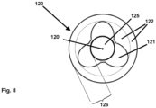
- the interface between the first and second permanent magnet element 121, 122, is not cylindrical (or essentially cylindrical)) is schematically and exemplarily illustrated (in a sectional view and in a projection parallel to the rotor axis of rotation 120') in Figure 8 :
- this contour or profile comprises radially outward reaching protrusions (at three specific angles around the rotor axis of rotation 120' - i.e. around the rotor axis of rotation 120', these three angles of maximum radial extension of the first permanent magnet element 121 are roughly 120° spaced).
- protrusions around the rotor axis of rotation 120'
- a different number of such protrusions is, likewise, possible, e.g. only two protrusions, or four protrusions, or five protrusions or six protrusions or more than six protrusions.
- the (contour or profile of the) protrusions might be differently shaped than shown in the representation of Figure 8 , e.g. having the profile of a triangle, or of a square, or of a pentagon or of a hexagon.
- Figure 6 shows - likewise by means of a cross-sectional representation along the rotation axis 120' of the rotor 120 - still another embodiment according to the present invention where the first and second hard magnetic materials (or the first and second permanent magnet element 121, 122) are located axially adjacent along a part of the shaft element 125 and parallel to the rotor axis of rotation 120'.
- the radial extension of both the first and the second hard magnetic materials (or first and second permanent magnet element 121, 122) are essentially identical, and the first and second permanent magnet elements 121, 122 are located adjacent along the shaft element 125 of the rotor 120.
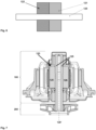
- Figure 5 schematically and exemplarily illustrates the method for manufacturing the rotor permanent magnet 126 of the rotor 120 for a synchronous motor according to the present invention:
- this method comprises the steps of the first hard magnetic material is molded, especially essentially axially around the shaft element 125, and, furthermore, the step of the second hard magnetic material being molded, especially essentially axially around the shaft element 125 and/or around the first hard magnetic material.
- These steps are schematically shown in the upper and lower parts of Figure 6 : The upper part shows the shaft element 125 being positioned inside a first tool comprising a first magnetic cage 121'.
- the extension of the first permanent magnet element 121 is defined, and the first permanent magnet element 121 is realized by means injection molding the first hard magnetic material.
- the lower part shows the shaft element 125 (together with the first hard magnetic material or the first permanent magnet element 121 already molded, i.e. being in place) being positioned inside a second tool comprising a second magnetic cage 122'.
- the extension of the second permanent magnet element 122 is defined, and the first permanent magnet element 122 is realized by means injection molding the second hard magnetic material.
- the first magnetic cage 121' is used during the first step and/or the second magnetic cage 122' is used during the second step in order to realize respective specific first and/or specific second magnetization pattern of (or within) the first and/or second hard magnetic material and/or of (or within) the first and/or second permanent magnet elements 121, 122.
Landscapes
- Engineering & Computer Science (AREA)
- Power Engineering (AREA)
- Manufacturing & Machinery (AREA)
- Physics & Mathematics (AREA)
- Electromagnetism (AREA)
- Permanent Field Magnets Of Synchronous Machinery (AREA)
Priority Applications (2)
| Application Number | Priority Date | Filing Date | Title |
|---|---|---|---|
| EP23307174.5A EP4572091A1 (de) | 2023-12-11 | 2023-12-11 | Synchronmotor mit mindestens einem stator und einem rotor mit einem rotorpermanentmagneten, verfahren zur herstellung eines rotorpermanentmagneten eines rotors für einen synchronmotor |
| CN202411400576.7A CN120150398A (zh) | 2023-12-11 | 2024-10-09 | 包括至少一个定子和转子的同步马达,该转子包括转子永磁体,用于制造用于同步马达的转子的转子永磁体的方法 |
Applications Claiming Priority (1)
| Application Number | Priority Date | Filing Date | Title |
|---|---|---|---|
| EP23307174.5A EP4572091A1 (de) | 2023-12-11 | 2023-12-11 | Synchronmotor mit mindestens einem stator und einem rotor mit einem rotorpermanentmagneten, verfahren zur herstellung eines rotorpermanentmagneten eines rotors für einen synchronmotor |
Publications (1)
| Publication Number | Publication Date |
|---|---|
| EP4572091A1 true EP4572091A1 (de) | 2025-06-18 |
Family
ID=89386136
Family Applications (1)
| Application Number | Title | Priority Date | Filing Date |
|---|---|---|---|
| EP23307174.5A Pending EP4572091A1 (de) | 2023-12-11 | 2023-12-11 | Synchronmotor mit mindestens einem stator und einem rotor mit einem rotorpermanentmagneten, verfahren zur herstellung eines rotorpermanentmagneten eines rotors für einen synchronmotor |
Country Status (2)
| Country | Link |
|---|---|
| EP (1) | EP4572091A1 (de) |
| CN (1) | CN120150398A (de) |
Citations (3)
| Publication number | Priority date | Publication date | Assignee | Title |
|---|---|---|---|---|
| US20150097458A1 (en) * | 2012-04-16 | 2015-04-09 | Otis Elevator Company | Permanent Magnet Electric Machine |
| WO2015146005A1 (ja) * | 2014-03-26 | 2015-10-01 | パナソニックIpマネジメント株式会社 | 磁石組立体、この磁石組立体を有する回転子、この回転子を備える電動機 |
| US20230318372A1 (en) * | 2020-09-09 | 2023-10-05 | Mitsubishi Electric Corporation | Rotor, motor, blower, and air conditioner |
-
2023
- 2023-12-11 EP EP23307174.5A patent/EP4572091A1/de active Pending
-
2024
- 2024-10-09 CN CN202411400576.7A patent/CN120150398A/zh active Pending
Patent Citations (3)
| Publication number | Priority date | Publication date | Assignee | Title |
|---|---|---|---|---|
| US20150097458A1 (en) * | 2012-04-16 | 2015-04-09 | Otis Elevator Company | Permanent Magnet Electric Machine |
| WO2015146005A1 (ja) * | 2014-03-26 | 2015-10-01 | パナソニックIpマネジメント株式会社 | 磁石組立体、この磁石組立体を有する回転子、この回転子を備える電動機 |
| US20230318372A1 (en) * | 2020-09-09 | 2023-10-05 | Mitsubishi Electric Corporation | Rotor, motor, blower, and air conditioner |
Also Published As
| Publication number | Publication date |
|---|---|
| CN120150398A (zh) | 2025-06-13 |
Similar Documents
| Publication | Publication Date | Title |
|---|---|---|
| US9401631B2 (en) | Brushless DC motor with permanent magnet rotor | |
| EP2573917B1 (de) | Verfahren zur Herstellung eines Rotors und eines bürstenlosen Innenrotormotors | |
| US6765319B1 (en) | Plastic molded magnet for a rotor | |
| CN100568669C (zh) | 电动机转子 | |
| CN111954971A (zh) | 电动马达 | |
| CN111615779A (zh) | 用于电机或电磁发电机、具有卡扣配合到相关联齿上的单个绕组支撑件的定子 | |
| JP2016082643A (ja) | ステータ | |
| CN109075653B (zh) | 具有优化的冷却的旋转电机 | |
| US20200186000A1 (en) | Motor and pump device | |
| US5889343A (en) | Electromechanical machine having improved lead wire sealing arrangement | |
| EP4572091A1 (de) | Synchronmotor mit mindestens einem stator und einem rotor mit einem rotorpermanentmagneten, verfahren zur herstellung eines rotorpermanentmagneten eines rotors für einen synchronmotor | |
| CN212751935U (zh) | 一种电机及其转子 | |
| JP2016537952A (ja) | 電気モーター | |
| CN103973007A (zh) | 永磁无刷电机 | |
| CN212751936U (zh) | 一种电机及其转子 | |
| CN213521434U (zh) | 一种电机及其转子 | |
| WO2000074209A1 (en) | Shrink-fit tubing for magnetic segments | |
| CN113765289B (zh) | 马达、马达单元 | |
| CN216390625U (zh) | 马达的转子和包括马达的转子的马达 | |
| CN110402529A (zh) | 电机 | |
| CN112272913B (zh) | 电动机及用于该电动机的线圈 | |
| EP2963775A1 (de) | Flüssigkeitsdichter Speichenrotor | |
| US10749421B2 (en) | Rotor for IPM motor, IPM motor, and method of manufacturing the rotor for IPM motor | |
| JP2017099176A (ja) | 界磁用永久磁石 | |
| CN103872843B (zh) | 螺杆马达及其制造方法 |
Legal Events
| Date | Code | Title | Description |
|---|---|---|---|
| PUAI | Public reference made under article 153(3) epc to a published international application that has entered the european phase |
Free format text: ORIGINAL CODE: 0009012 |
|
| STAA | Information on the status of an ep patent application or granted ep patent |
Free format text: STATUS: REQUEST FOR EXAMINATION WAS MADE |
|
| 17P | Request for examination filed |
Effective date: 20241121 |
|
| AK | Designated contracting states |
Kind code of ref document: A1 Designated state(s): AL AT BE BG CH CY CZ DE DK EE ES FI FR GB GR HR HU IE IS IT LI LT LU LV MC ME MK MT NL NO PL PT RO RS SE SI SK SM TR |