EP4572016A2 - Systèmes, éléments et procédés d'antenne gnss - Google Patents
Systèmes, éléments et procédés d'antenne gnss Download PDFInfo
- Publication number
- EP4572016A2 EP4572016A2 EP25171367.3A EP25171367A EP4572016A2 EP 4572016 A2 EP4572016 A2 EP 4572016A2 EP 25171367 A EP25171367 A EP 25171367A EP 4572016 A2 EP4572016 A2 EP 4572016A2
- Authority
- EP
- European Patent Office
- Prior art keywords
- petal
- dipole
- petals
- metallized
- pair
- Prior art date
- Legal status (The legal status is an assumption and is not a legal conclusion. Google has not performed a legal analysis and makes no representation as to the accuracy of the status listed.)
- Pending
Links
Images


Classifications
-
- H—ELECTRICITY
- H01—ELECTRIC ELEMENTS
- H01Q—ANTENNAS, i.e. RADIO AERIALS
- H01Q9/00—Electrically-short antennas having dimensions not more than twice the operating wavelength and consisting of conductive active radiating elements
- H01Q9/04—Resonant antennas
- H01Q9/16—Resonant antennas with feed intermediate between the extremities of the antenna, e.g. centre-fed dipole
- H01Q9/28—Conical, cylindrical, cage, strip, gauze, or like elements having an extended radiating surface; Elements comprising two conical surfaces having collinear axes and adjacent apices and fed by two-conductor transmission lines
- H01Q9/285—Planar dipole
-
- G—PHYSICS
- G01—MEASURING; TESTING
- G01S—RADIO DIRECTION-FINDING; RADIO NAVIGATION; DETERMINING DISTANCE OR VELOCITY BY USE OF RADIO WAVES; LOCATING OR PRESENCE-DETECTING BY USE OF THE REFLECTION OR RERADIATION OF RADIO WAVES; ANALOGOUS ARRANGEMENTS USING OTHER WAVES
- G01S19/00—Satellite radio beacon positioning systems; Determining position, velocity or attitude using signals transmitted by such systems
- G01S19/01—Satellite radio beacon positioning systems transmitting time-stamped messages, e.g. GPS [Global Positioning System], GLONASS [Global Orbiting Navigation Satellite System] or GALILEO
- G01S19/13—Receivers
- G01S19/35—Constructional details or hardware or software details of the signal processing chain
- G01S19/36—Constructional details or hardware or software details of the signal processing chain relating to the receiver frond end
-
- H—ELECTRICITY
- H01—ELECTRIC ELEMENTS
- H01Q—ANTENNAS, i.e. RADIO AERIALS
- H01Q21/00—Antenna arrays or systems
- H01Q21/06—Arrays of individually energised antenna units similarly polarised and spaced apart
- H01Q21/061—Two dimensional planar arrays
- H01Q21/062—Two dimensional planar arrays using dipole aerials
-
- H—ELECTRICITY
- H01—ELECTRIC ELEMENTS
- H01Q—ANTENNAS, i.e. RADIO AERIALS
- H01Q21/00—Antenna arrays or systems
- H01Q21/06—Arrays of individually energised antenna units similarly polarised and spaced apart
- H01Q21/20—Arrays of individually energised antenna units similarly polarised and spaced apart the units being spaced along or adjacent to a curvilinear path
- H01Q21/205—Arrays of individually energised antenna units similarly polarised and spaced apart the units being spaced along or adjacent to a curvilinear path providing an omnidirectional coverage
-
- H—ELECTRICITY
- H01—ELECTRIC ELEMENTS
- H01Q—ANTENNAS, i.e. RADIO AERIALS
- H01Q21/00—Antenna arrays or systems
- H01Q21/24—Combinations of antenna units polarised in different directions for transmitting or receiving circularly and elliptically polarised waves or waves linearly polarised in any direction
- H01Q21/26—Turnstile or like antennas comprising arrangements of three or more elongated elements disposed radially and symmetrically in a horizontal plane about a common centre
-
- H—ELECTRICITY
- H01—ELECTRIC ELEMENTS
- H01Q—ANTENNAS, i.e. RADIO AERIALS
- H01Q25/00—Antennas or antenna systems providing at least two radiating patterns
- H01Q25/001—Crossed polarisation dual antennas
Definitions
- This patent application relates to global navigation satellite systems and more particularly to antennas, antenna elements and antenna assemblies employing one or more pairs of antenna elements each electromagnetically coupled to a dipole with enhanced azimuthal performance and/or wide bandwidth high precision high purity reception.
- GNSS global navigation satellite systems
- GNSS global navigation satellite systems
- Such receivers provide for a ubiquitous and global time reference, in addition to a host of geolocation uses, ranging from consumer navigation devices to means to monitor global warming to precision agriculture and of course, military applications.
- GNSS Global Navigation Satellite Systems
- GNSS receivers are commonly designed and configured to receive signals from multiple constellations, such as the European Galileo, Russian GLONASS, US GPS, and Chinese Beidou Global Navigation Systems, plus at least two regional positioning and timing systems such as the Indian NAVIC and Japanese QZSS systems.
- the most widely used usage of GNSS receivers is in consumer products such as vehicle navigation system, personal navigation systems etc. where a typical accuracy to within 2 meters (4m in diameter) 95% of the time when stationary is achieved but electronic processing and filtering within the associated software processing the received GNSS signals either smooths statistical variations or snaps a location icon to a "most likely" feature on a map such that consumer level tracking usually appears to be more accurate than it is in fact.
- GNSS receivers can provide true locations to within 10cm, or with corrections data, within 2-3cm, or to within 1-2 mm for stationary systems with lengthy integration periods.
- Such precision GNSS receivers receive signals on two or more frequencies and employ complex models for the troposphere and ionosphere in order to estimate signal times of flight from the multiple satellites employed in establishing an accurate position in three dimensions. Additionally, such systems exploit data transmitted by the satellites within the navigation signals relating to errors in the position and time estimates of a satellite which can arise from factors such as the orbital conditions encountered by the satellite.
- the peak RF power flux density (PFD) of GNSS signals on the surface of the earth is approximately -120 dBm and decreases as the satellite(s) get close to the horizon. Accordingly, if there are sufficient satellites accessible the GNSS receiver may selectively employ the signals from satellites at high altitude with higher PFD. However, it would be beneficial for the GNSS receiver to have the ability to track signals down to the horizon. The ability to achieve this is entirely dependent upon the quality of the signals delivered by the GNSS antenna to the GNSS receiver. In addition to clear reception of extremely low level RF signals, it is also important that the phases for each of the received signals be independent of the angles of incidence on the antenna. Further, GNSS receivers must support reception of circularly polarized signals.
- the present invention is directed to global navigation satellite systems and more particularly to antennas, antenna elements and antenna assemblies employing one or more pairs of antenna elements each electromagnetically coupled to a dipole with enhanced azimuthal performance and/or wide bandwidth high precision high purity reception.
- references to terms “including”, “comprising”, “consisting” and grammatical variants thereof do not preclude the addition of one or more components, features, steps, integers, or groups thereof and that the terms are not to be construed as specifying components, features, steps, or integers.
- the phrase “consisting essentially of”, and grammatical variants thereof, when used herein is not to be construed as excluding additional components, steps, features integers or groups thereof but rather that the additional features, integers, steps, components or groups thereof do not materially alter the basic and novel characteristics of the claimed composition, device or method. If the specification or claims refer to "an additional" element, that does not preclude there being more than one of the additional element.
- references to terms such as “perpendicular”, “along”, “parallel” and grammatical variants thereof in respect to alignment and / or direction should be considered not as absolute but as having a tolerance to variation thereof such that these directions and/or alignments are “substantially” as indicated. Tolerances to these being as established, for example, through manufacturing tolerances, performance tolerances, manufacturing costs etc.
- Angle angle refers to a rotation angle in the X-Y plane centered on the origin, and relative to a defined direction.
- Eletitude refers to the angle subtended between the Poynting vector of the incident plane wave, and the X-Y (ground) plane. Accordingly, a wave of grazing incidence from the horizon has a near zero elevation angle whilst a wave incident vertically has a 90 degree elevation angle.
- Axial ratio refers to a measure of the extent to which an antenna is able to reject circularly polarized signals of the unwanted polarization (a second rotational sense) relative to the wanted polarization (a first rotational sense), and is a measure of the ability to reject multipath signals which is an important parameter for precision antennas.
- Phase center offset refers to a concept that there is a region associated with an antenna which tends to a point for a perfect antenna, from within which or at, all signals may be considered to have been received at or transmitted from. This is a virtual region/point in space typically centered just above the midpoint of the physical antenna and is a measure of the limits of knowledge of an antenna's position in space.
- Phase center variation refers to a measure of the apparent phase center movement over all incident angles for plane waves (i.e. around all azimuths and all elevation angles) and over all frequencies in the bandwidth.
- An ideal antenna having a phase center variation of zero.
- a "petal” as used herein refers to a metallized antenna structure either free-standing, supported by a frame, patterned onto a substrate, or patented onto a substrate or carrier supported by a frame which provides a receiving antenna element for a GNSS antenna.
- petal refers to the metallized antenna structure and any substrate or carrier together with ancillary elements for mechanical attachment / retention of the petal discretely or in an array of petals with one or more other elements of the GNSS antenna.
- petal refers to the metallized antenna structure.
- a “dipole antenna” (commonly referred to as a dipole) as used herein refers to, but is not limited to, any one of a class of antennas producing a radiation pattern approximating that of an elementary electric dipole with a radiating structure supporting a line current so energized that the current has only one node at each end.
- a "radome” as used herein refers to, but is not limited to, an environmental housing or cover within which an antenna, e.g. a GNSS antenna, is housed which is transparent to wireless signals in the frequencies of interest.
- an antenna e.g. a GNSS antenna
- a GNSS “rover” antenna as used herein refers to, but is not limited to, a GNSS antenna addressing real-time kinematic (RTK) and mobile (roving) applications.
- RTK real-time kinematic
- roving mobile
- a “CubeSat” as used herein refers to, but is not limited to, a U-class spacecraft which is a form of miniaturized satellite which is made up of multiples of 10 cm ⁇ 10 cm ⁇ 10 cm cubic units (4" x 4" x 4)).
- a CubeSat may employ commercial off-the-shelf (COTS) components for their electronics and structure.
- COTS commercial off-the-shelf
- GNSS receivers are employed within a wide range of applications within both the civil and military markets.
- One such dominant configuration for dual band receivers for civilian applications is the use of the L1 + L2 bands of the GPS system (formerly Navstar GPS).
- the operating frequency bands for GPS L1 and GPS L2 being listed below in Table 1 together with the frequency bands of the other major GNSS systems introduced in the 2000s, namely Beidou, Galileo, GLONASS, GPS, and NAVIC. System Beidou Galileo GLONASS Owner China Europe Russia Freq.
- L5 offers several benefits including, but not limited to, twice as L2, being within a band designated by the International Telecommunication Union (ITU) for the Aeronautical Radio-Navigation Services (ARNS) which is less prone to interference with ground based navigation aids, and sharing the same frequency space as the E5A signal from Galileo.
- ITU International Telecommunication Union
- ALANS Aeronautical Radio-Navigation Services
- GNSS receivers compatible with the GPS and Galileo systems for example, allowing a device comprising such a receiver to be employed in regions where one or both GNSS systems are accessible.
- a GNSS antenna requires consideration of a range of characteristics including, for example, the ability for tracking satellites at low elevation, phase centre variation (PCV), antenna efficiency and impedance, axial ratio and up-down ratio (UDR), antenna bandwidth, etc. whilst also providing a light weight, compact and robust form factor. Whilst the following description and embodiments of the invention are directed towards a GNSS rover antenna it would be evident to one of skill in the art that the designs and principles outlined may be employed in the design and implementation of GNSS antennas for other applications and scenarios without departing from the scope of the invention.
- PCV phase centre variation
- UDR up-down ratio
- PPP correction data is broadcast from geostationary satellites, which generally subtend low elevation angles to many densely populated regions such as Europe and much of North America.
- the link margin of L band signals is typically low (or thin), so that improved gain at these elevation angles is an important attribute for a GNSS antenna. This issue is exacerbated at satellite beam edges and northern latitudes, where the link margin is further challenged and a difference of just 1dB in antenna gain or antenna noise figure can make a significant difference in correction availability.
- a key design parameter in this respect is the antenna gain-to-noise temperature (G/T) which is the ratio of the antenna element gain divided by the receiver system noise temperature, typically determined by the antenna noise figure.
- G/T antenna gain-to-noise temperature
- the inventors have targeted a G/T objective for GNSS antenna according to embodiments of the invention of -25.5dB/K at a 10° elevation angle.
- GNSS antenna elements such as patches and crossed dipoles
- the polarization response of these prior art GNSS antenna elements also becomes linear at the lower elevation angles, due to the existence of a ground plane, necessary to increase gain in the hemisphere above the antenna.
- Improved gain close to the horizon also increases the ability of the receiver to track low elevation satellites with a concomitant improvement in the dilution of precision parameter (DOP), which is a metric related to pseudorange measurement accuracy.
- DOP precision parameter
- this provides an antenna gain at horizon, at best, of about -5 dBic, which is insufficient for optimized L band correction usage.
- different antenna types such as helical elements have been proposed to overcome this issue, but their cylindrical shape and longer length makes them unsuitable for many applications, particularly roving (or rover) applications.
- the helix suffers from back lobes that can make the antenna more susceptible to reception of multipath signals incident below the positive hemisphere of the antenna.
- Phase Centre Variation The phase centre of an ideal antenna is a notional point in space at which all signals are received or transmitted from, independent of the frequency, or elevation or azimuth angle of signal incidence.
- PCV Phase Centre Variation
- Correction data for phase center variation is commonly encoded in a standardized file, e.g. an Antenna Exchange Format (ANTEX) file, which can be applied concurrently for precision applications.
- ANTEX Antenna Exchange Format
- the PCV corrections data provided in the ANTEX file are usually provided as a function of elevation and frequency, but with averaged azimuth data for each elevation and frequency (designated "noazi" corrections).
- noazi averaged azimuth data for each elevation and frequency
- the net system error is the RMS sum of the base and rover antenna phase center variations. It is usually possible to accommodate larger base station antennas, which can commonly provide PCVs approaching +/- 1mm (e.g. from Tallysman ® VeraPhase TM or VeraChoke TM antennas).
- Antenna Efficiency can be narrowly defined in terms of copper losses of the radiating elements but feed network losses also contribute and accordingly, a design objective should be the optimization of both. It is generally known by those of skill in the art that physically wide radiating elements are a key requirement for wider bandwidth and that copper presents a good compromise for the radiator metal. Within the design as described below in Section 2 wide physical petals are employed although it would be evident that in narrow band applications alternate petal designs with narrower geometries may be employed without departing from the scope of the invention. Similarly, the experimental results described in Section 3 exploit copper as the petal metallization although it would be evident that other materials may be employed including, for example, silver offers improved conductivity but is expensive.
- the petals are parasitic resonators that are tightly coupled to a distributed feed network, which in itself is intrinsically narrowband. Accordingly, the resulting wide bandwidth response of the GNSS antenna according to embodiments of the invention results from the load on the feed network provided by the excellent wideband radiation resistance of the petals.
- petals are employed in conjunction with a dipole for each orthogonal exciter axis wherein the pair of orthogonal exciter axes are electrically independent and highly isolated electrically (better than -30dB within fabricated GNSS antenna according to embodiments of the invention), even with the parasitic petal coupling.
- the two axis are then driven independently, in phase quadrature as derived from hybrid couplers, for example, within the associated microwave/RF circuit associated with the GNSS antenna which may be implemented upon a PCB forming part of the GNSS antenna or an external circuit.
- the resulting GNSS antenna according to embodiments of the invention combining inherently efficient parasitic petals combined with a low loss distributed feed network result in a highly efficient GNSS antenna structure offering superior performance to prior art solutions.
- AR Axial Ratio
- UDR Up-Down Ratio
- AR characterizes the performance of the antenna's ability to receive circular signals whilst the UDR is the ratio of gain pattern amplitude at a positive elevation angle ( ⁇ ) to the maximum gain pattern amplitude at its mirror image (- ⁇ ).
- Good AR and UDR across the full bandwidth of the antenna is required to ensure the purity of the reception of the RHCP signals within GNSS systems and to mitigate multipath effects.
- GNSS signals reflected from the ground, buildings, or metallic structures such as vehicles are delayed and the purity of their RHCP signals is degraded with Left Hand Circular Polarized (LHCP) signals.
- LHCP Left Hand Circular Polarized
- a wide GNSS bandwidth antenna allows the system employing it to achieve positioning based on GNSS signals from multiple constellations, e.g. satellites from multiple GNSS systems.
- GNSS signals from multiple constellations, e.g. satellites from multiple GNSS systems.
- a wide bandwidth GNSS antenna allows for the implementation of three-carrier and multicarrier ambiguity resolution techniques to obtain the highest possible precision.
- a GNSS antenna it would be beneficial for a GNSS antenna to be capable of reception over the full GNSS frequency bandwidth from 1.15GHz to 1.60GHz.
- the GNSS antenna according to an embodiment of the invention whose results are presented in Section 4 were for a small and light weight radiating element (given the full bandwidth requirement) with a ground plane size of approximately 100 mm (4 inches), an element height of 30mm or lower (1.2" or lower), and a weight of 100 grams or less (3.5 ounces or less). It would be evident that smaller versions of this GNSS antenna may be implemented exploiting embodiments of the invention albeit with different performance.
- Applications for GNSS antennas according to embodiments of the invention may include, but not be limited to, housed antennas (such as RTK rovers) and also a lightweight antennae suitable for mobile applications like such as drones, UAVs, CubeSats, etc.
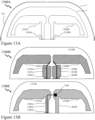
- FIG. 13A the minimum structure for an antenna is depicted in cross-sectional view 1300A embodying these design elements is presented comprising a pair of Petals 110 with a dipole formed from first and second Dipole Elements 1320A and 1330A.
- first and second Dipole Elements 1320A and 1320B are formed upon a Carrier 1310A, e.g. a PCB, and are coupled to first and second feed points (FPs) 1330A and 1330B respectively.
- FPs feed points
- a plan view 1100 of the pair of petals 110 is depicted in Figure 11 with the two Petals 110 evident opposite each other with a common central axis X-X which would be aligned with the carrier 1310 and the first and second dipole elements 1310A and 1310B respectively. Also depicted in plan view 1100 at the distal ends of each Petal 110 are a pair of Tabs 130 as described below in respect of Figure 1 and Solder Pads 1010 as described below in respect of Figure 10 . As depicted the pair of Petals 110 are joined via an unmetallized portion of the carrier, Element 1110, which the Petals 110 have been formed upon.
- first and second electrical configurations 1300B and 1300C respectively for coupling a dipole to an external electrical circuit.
- first electrical configuration 1300B a first Dipole Element 1340A is coupled to a first FP 1360A via first Track 1350A which is part of a first Transmission Line 1355A between the first FP 1360A and the first Dipole Element 1340A.
- a second Dipole Element 1340B is coupled to a second FP 1360B via second Track 1350B which is part of a second Transmission Line 1355B between the second FP 1360B and the second Dipole Element 1340B.
- first electrical configuration 1300A is driven through both first FP 1360A and second FP 1360B.
- first and second Dipole Elements 1320A and 1320B are also implemented on the other side of the Carrier 1310B where the two electrical structures on either side of the Carrier 1310B are electrically connected through a plurality of vias, not depicted for clarity.
- a first Dipole Element 1370A is coupled to a first FP 1390A via first Feed Track385A and a second Dipole Element 1370B is coupled to a second Feed Track385B. Also depicted coupled to the first FP 1390A and the second Dipole Element 1370B is a first Transmission Line 1380A which terminates in Pad 1395 upon the second Dipole Element 1370B.
- first electrical connection 1300B where dipole comprising the first and second Dipole Elements 1340A and 1340B are each coupled to unbalanced lines from the first and second FPs 1360A to 1360B
- the dipole in second electrical configuration 1300C is fed from a single FP 1390 and incorporates a balanced-unbalanced (balun) connection so that the first and second Dipole Elements 1370A and 1370B operate in a balanced manner with an unbalanced feed from first FP 1390A.
- the integrated balun in second electrical configuration 1300C has an electrical impedance close to a target 50 ⁇ impedance where matching to the target 50 ⁇ impedance at the FP 1390A is achieved through the appropriate design parameters for the transmission line comprising first Feed Track385A and first Transmission Line 1380A.
- the first and second Dipole Elements 1370A and 1370B with or without the first and second Feed Tracks385A and 1385B respectively are also implemented on the other side of the Carrier 1310B where the two electrical structures on either side of the Carrier 1310C are electrically connected through a plurality of vias, not depicted for clarity.
- GNSS antenna employing receiving elements each comprising a pair of opposing petals which are electromagnetically coupled to a dipole and therein to an RF receiver circuit. Subsequently, an overview of the operating principle of a GNSS antenna employing said receiving elements comprising a pair of opposing petals which are electromagnetically coupled to a dipole is presented.
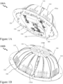
- FIGS. 1A and 1B there are depicted lower and upper perspective views 100A and 100B respectively of a GNSS antenna according to an embodiment of the invention.
- a GNSS Antenna according to an embodiment of the invention in Figure 1A an array of Petals 110 is mounted to a printed circuit board (PCB) 120 via Tabs 130 on the Petals 110 inserted into slots within the PCB 120.
- PCB printed circuit board
- the array of Petals 110 is similarly depicted mounted to a printed circuit board (PCB) 120.
- the array of Petals 110 comprises eight (8) Petals 110 although as described and depicted below in respect of Figures 10 to 12 an antenna exploiting embodiments of the invention may employ 2 or 4 Petals 110.
- N the number of Petals 110
- FIG 1B Also depicted in Figure 1B are Mounting Holes 160 within the PCB 120 for attaching the antenna to a radome, base of a radome, a choke ring etc.
- first and second Artefacts 170A and 170B which are artefacts arising from the computer aided design (CAD) software employed in generating the images presented within Figures 1A to 6 respectively, Figures 6A to 7B respectively, and Figure 8 .
- First Artefacts 170A being the sides of elements within the array of Petals 110 which support the carrier(s) and/or substrate(s) onto which the array of Petals 110 is implemented via metallization and/or the Petals 110 directly.
- Second Artefacts 170B being the tops of these elements.
- first and second Artefacts 170A and 170B arise due to the CAD software treating the carrier for the array of Petals 110 and/or the Petals 110 as transparent.
- the Electronics 140 provides a microwave / RF circuit which, in the instance that the GNSS antenna is a receiver, combines the received RF / microwave signals at the feed points (FPs) of the plurality of dipoles to generate an RF/microwave output signal coupled to the RF Connector 150. Accordingly, considering the instance of a pair of dipoles disposed at right angles to one another then there are 4 FPs.
- the Electronics 140 thereby comprises a pair of hybrid couplers, which each couple the RF/microwave signals from a pair of FPs to a common output port, and a balun, which receives the signals from the common output ports of the pair of hybrid couplers and combines them to generate the signal coupled to the RF Connector 150 at the output of the Balun.
- the microwave / RF signals from the FPs have a relative phase difference sequentially of 0°, 90°, 180°, and 270° then these signals are initially combined within each of the hybrid couplers and then within the Balun. Accordingly, based upon this described sequence of phases coupled from the FPs to the hybrid couplers the GNSS antenna may operate to receive right hand circularly polarized signals.
- the GNSS antenna may be configured to receive left hand circularly polarized signals or within other embodiments of the invention provide a GNSS antenna for a transmitter generating right hand polarized signals or left hand polarized signals.
- the Balun may be a transformer.
- the four FPs are located within Region 180 projecting through the PCB 120.
- the dipoles may employ integrated baluns such that only a pair of FPs are required, one for each dipole, where the balun provides the out-of-phase phase differences for the pair of dipole elements within each dipole.
- an antenna may employ a single dipole with a single pair of Petals 110.
- an antenna may employ three dipoles mounted at 120° to each other with 6 Petals 110 such that the antenna receives or transmits signals with relative phase differences of 0°, 60°, 120°, 180°, 240° and 270°. It would be evident that other configurations could be implemented without departing from the scope of the invention.
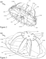
- FIG. 2 there is depicted a lower perspective view 200A of a GNSS antenna according to an embodiment of the invention with the PCB 120removed. Accordingly, Figure 2 depicts a similar perspective to that of lower perspective view 100A in Figure 1A with the PCB 120 removed. Accordingly, the array of Petals 110 is depicted together with the first Artefacts 170A. Also depicted is an Isolation Block 240 through the bottom of which project the FPs within Region 180. The FPs being formed upon the dipoles, a pair of FPs being disposed upon a first circuit board Dipole A 220 and a further pair of FPs disposed upon a second circuit board Dipole B 230.
- Dipole A 220 and Dipole B 230 being disposed orthogonally to one another. Also depicted are first to fourth Supports 210A to 210D where these are disposed radially within the GNSS antenna. Each of the first to fourth Supports 210A to 210D being disposed between one end of Dipole A 220 and an end of Dipole B 230. Accordingly, the first to fourth Supports 210A to 210D support additional Petals 110 within the array of Petals 110 which are disposed between the Petals 110 associated with the Dipole A 220 and Dipole B 230.
- FIG. 3 there is depicted an upper perspective view 300 of a GNSS antenna according to an embodiment of the invention with the array of Petals 110 removed. Accordingly, Figure 3 depicts a similar perspective to that of upper perspective view 100B in Figure 1B with the array of Petals 110 removed. Accordingly, there are depicted the orthogonally disposed Dipole A 220 and Dipole B 230 together with the first to fourth Supports 210A to 210D respectively. Located at the centre is Isolation Block 240.
- each of Dipole A 220 and Dipole B 230 comprises FPs which similarly fit through slots within the PCB 120 in the Region 150 and engage with slots formed within the Isolation Block 240.
- the lower inner ends of each of the first to fourth Supports 210A to 210D also engage with features on the external surface of the Isolation Block 240.
- the orientation of each of the Dipole A 220, Dipole B 230 and first to fourth Supports 210A to 210D respectively being defined by these engagements with the PCB 120 and Isolation Block 240 and the Support Frame 310 where the upper region of each of these elements engages a slot within the Support Frame 310.
- each of the Dipole A 220, Dipole B 230 and first to fourth Supports 210A to 210D respectively are orientated substantially perpendicular to the PCB 120. It would be evident to one of skill in the art that other mechanical means to locate, orientate and retain the Dipole A 220, Dipole B 230 and the first to fourth Supports 210A and 210D may be employed without departing from the scope of the invention.
- FIG. 3B there is depicted a partially exploded assembly 300B of the Dipole A 220, Dipole B 230, first to fourth Supports 210A to 210D and Mounting Block 240 for a GNSS antenna according to an embodiment of the invention.
- the Mounting Block 240 are the slots allowing insertion of the Dipole A 220 and Dipole B 230 so that the FPs project through the bottom of the Mounting Block 240 and therein the PCB 120 in the final assembly.
- the Mounting Block 240 also provides a benefit in the microwave/RF domain for performance of a GNSS antenna according to an embodiment of the invention.
- each of Dipole A 220 and Dipole B 230 is depicted as being configured according to the description above and as depicted in respect of second electrical configuration 1300C in Figure 13 with the exception that the transmission line, balun etc. have been omitted for clarity.
- Dipole A 220 and Dipole B 230 when assembled Dipole A 220 and Dipole B 230 have disposed closed to the point they intersect a pair of metallized lines (one from each of Dipole A 220 and Dipole B 230) run vertically parallel to one another thereby forming another parasitic transmission line through the intervening medium, e.g. air where no Mounting Block 240 is provided.
- the intervening medium e.g. air where no Mounting Block 240 is provided.
- the metallization is only on one side of each of Dipole A 220 and Dipole B 230 then a single parasitic transmission line may be formed whilst when both sides of each of Dipole A 220 and Dipole B 230 are metallized then four parasitic transmission lines may be formed.
- the Mounting Block 240 provides a different dielectric constant for part or all of each parasitic transmission line wherein appropriate selection of the material and hence dielectric constant of the Mounting Block 240 the es the frequency at which these parasitic transmissions lines "operate” outside the operating frequency range of the GNSS antenna.
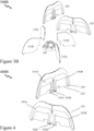
- FIG. 4 there is depicted an exploded perspective view 400 of a pair of orthogonally positioned dipoles for a GNSS antenna according to an embodiment of the invention.
- Dipole A 220 and Dipole B 230 are depicted separated vertically.
- Dipole A 220 having first and second Dipole Metallizations 410A and 410B each forming one half of a dipole.
- First Dipole Metallization 410A being electrically coupled to first FP 430A at the left central lower portion of Dipole A 220 whilst second Dipole Metallization 410B is electrically coupled to second FP 430B at the right central lower portion of Dipole A 220.
- third Dipole Metallization 420A is electrically coupled to third FP 430C at the left central lower portion of Dipole B 230 whilst fourth Dipole Metallization 420B is electrically coupled to fourth FP 430D at the right central lower portion of Dipole B 230.
- First to fourth FPs 430A to 430D being the FPs evident within the central Region 180 in lower perspective view 100A in Figure 1 and lower perspective views 200A and 200B in Figures 2 and 2B respectively.
- Also depicted in assembled and exploded perspective views 400A and 400B in Figures 4 and 4B respectively are Mounting Tabs 440 at the outer lower portion of each of Dipole A 220 and Dipole B 230.
- the Mounting Tabs 440 engaging slots within the PCB 120 for mounting the Dipole A 220 and Dipole B 230 to the PCB 120 and defining their relative orientation through the precision of the slots within the PCB 120 being at 90° to one another for mounting Dipole A 220 and Dipole B 230 respectively.
- the dipoles may employ integrated baluns such that only a pair of FPs are required, one for each dipole.
- the second FP 230B and third FP 230C may be coupled to the external microwave/RF circuit such that the first and second Dipole Metallizations 410A and 410B are coupled via the integrated balun (not shown for clarity) to second FP 430B and third and fourth Dipole Metallizations 420A and 420B are coupled via another integrated balun (not shown for clarity) to third FP 430C.
- second FP 430B may be replaced with first FP 430A and/or third FP 430C may be replaced with fourth FP 430D where the integrated baluns are employed.
- Dipole A 220 and Dipole B 230 have interlocking slots that provide for assembly of the crossed dipole arrangement according to an embodiment of the invention.
- other assembly configurations may be employed without departing from the scope of the invention to provide the pair of crossed dipoles using 2, 3, or 4 elements and other means of attachment and assembly without departing from the scope of the invention.
- the upper central edges of Dipole A 220 and Dipole B 230 as depicted within the embodiment of the invention are profiled to include an indent to support a stiffener attached to the flexible circuit forming the array of Petals 110 such as Support Frame 310 depicted and described above in respect of Figure 3 .
- Dipole A 220 and Dipole B 230 provide mechanical support for the respective Petals 110 of the array of Petals 110 to which they are associated.
- the array of Petals 110 may, within an embodiment of the invention be formed from a semi-flexible or flexible PCB with the array of Petals 110 imprinted in metallization upon the semi-flexible or flexible PCB.
- the semi-flexible or flexible PCB and hence the array of Petals 110 are in mechanical contact with the upper edges of Dipole A 220 and Dipole B 230 such that the electromagnetic coupling between the narrow band dipoles, Dipole A 220 and Dipole B 230, and the opposed metallized Petals 110 is determined by the predetermined distance between the metallized Petals 110 and the metallized dipoles imprinted on the dipoles thereby implementing a distributed feed network, wherein each of the metallized petals are devoid of direct connection to the external microwave/RF circuit, such as Electronics 140 depicted in Figure 1A .
- first and second images 500 and 600 respectively for the pair of dipoles for a GNSS antenna according to an embodiment of the invention.
- first image 500 in Figure 5 there is depicted a schematic of Dipole A 220 showing first Dipole Metallization 410A electrically coupled to first FP 430A at the left central lower portion of Dipole A 220 whilst second Dipole Metallization 410B is electrically coupled to second FP 430B at the right central lower portion of Dipole A 220.
- first Slot 510 which allows Dipole A 220 to be assembled with the Dipole B 230 which has a corresponding second Slot 520.
- Dipole A 220 may also have first and second Dipole Metallizations 410A and 410B implemented on the other side of Dipole A 220 where these two sides are electrically connected through a plurality of vias.
- Dipole B 230 shows third Dipole Metallization 420A electrically coupled to third FP 430C at the left central lower portion of Dipole B 230 whilst fourth Dipole Metallization 420B is electrically coupled to fourth FP 430D at the right central lower portion of Dipole B 230. Also depicted is second Slot 520 which allows Dipole B 230 to be assembled with the Dipole A 220 which has a corresponding first Slot 510.
- Dipole B 230 may also have third and fourth Dipole Metallizations 420A and 420B implemented on the other side of Dipole A 220 where these two sides are electrically connected through a plurality of vias.
- first image 500 in Figure 5 and second image 600 in Figure 6 representing Dipole A 220 and Dipole B 230 for the configuration described and depicted in respect of second electrical configuration 1300C in Figure 13B wherein each of Dipole A 220 and Dipole B 230 comprise integrated baluns.
- first image 500 in Figure 5 and second image 600 in Figure 6 only the ground tracks are depicted and the microstrip feed line, first Transmission Line 1380A and its electrical connection to the dipole element, Pad 1395, are omitted for clarity.
- first Dipole Metallization 410A is coupled to first FP 430A via a first Trace 530A and the second Dipole Metallization 410B is coupled to second FP 430A via a second Trace 530B.
- third Dipole Metallization 420A is coupled to third FP 430C via a third Trace 540A and the fourth Dipole Metallization 420B is coupled to fourth FP 430D via a second Trace 540B.
- the microstrip line, not depicted for clarity, for Dipole A 220 is coupled to the external microwave/RF feed at first Coupling Point 550.
- the microstrip line, not depicted for clarity, for Dipole B 230 is coupled to the external microwave/RF feed at second Coupling Point 560.
- the first FP 430A and fourth FP 430D are connected to ground and each of Dipole A 220 and Dipole B 230 are each connected to a single microwave/RF signal.
- an external microwave/RF feed network provides or receives 2 microwave/RF signals to an antenna comprising Dipole A 220 and Dipole B 230.
- Dipole A 220 and Dipole B 230 do not include integrated baluns.
- the first Trace 530A and second Trace 530B may be symmetrical mirror images and each is connected to its respective first and second FPs 430A and 430B respectively such that a pair of microwave/RF signals are coupled to/from Dipole A 220.
- the third Trace 530A and fourth Trace 530B may be symmetrical mirror images and each is connected to its respective third and fourth FPs 430C and 430D respectively such that a pair of microwave/RF signals are coupled to/from Dipole B 230.
- an external microwave/RF feed network provides or receives 4 microwave/RF signals to an antenna comprising Dipole A 220 and Dipole B 230.
- the lower edge of Dipole A 220 comprises first FP 430A and second FP 430B towards the center and Mounting Tabs 440 at the outer edges.
- the upper edge defines a central region for supporting a stiffener, e.g. Support Frame 310, and the array of Petals 110 whilst the outer upper edges define the curved surfaces to which the array of Petals 110 conforms when attached.
- the lower edge of Dipole B 230 comprises third FP 430C and fourth FP 430D towards the center and Mounting Tabs 440 at the outer edges.
- the upper edge defines a central region for supporting a stiffener, e.g. Support Frame 310, and the array of Petals 110 whilst the outer upper edges define the curved surfaces to which the array of Petals 110 conforms when attached.
- each dipole thereby comprises a pair of centrally disposed vertical metal traces which connect to the dipole elements at the inner end of each dipole metallization trace.
- the dipole PCB may be of substantially equal thicknesses to attachment slots within the PCB 120 to allow for accurate mounting of the dipoles relative to the ground plane formed within or upon PCB 120.
- each Dipole PCB may include identical copies of a balun.
- Dipole A 220 and Dipole B 230 define the predetermined distance between the metallized Petals 110 and the metallized dipoles imprinted on the dipoles thereby implementing a distributed feed network between the dipoles and Petals 110.
- the Petals 110 are devoid of a direct connection to the FPs and the microwave/RF circuit.
- Figures 5 and 6 it would be evident from Figures 5 and 6 that within the embodiment of the invention presented the dipoles vary in geometry radially and that the separation of the dipole metallization from the Petal 110 associated with it varies radially or from a different perspective varies with elevation angle.
- This separation of petal-dipole separation as a function of elevation angle being predetermined in dependence upon the GNSS antenna design such that either the upper edge of dipole elements is defined from the petal geometry or vice-versa. It would also be evident that the length of the dipole elements from their inner edge towards the middle of each of Dipole A 220 and Dipole B 230 to their outer point at the lower outer region of each of Dipole A 220 and Dipole 230 is determined by the requirement for the dipole elements to be electrically ⁇ /4 at the central frequency of the GNSS antenna.
- the inventors also established that whilst meeting this requirement and implementing the associated Petals 110 that the sensitivity of the impedance of the structure was less sensitive to the distance between the Petal 110 and dipole element towards the centre of the dipole allowing for increased flexibility in the overall design for the geometry of the Petals 110 relative to dipole. Accordingly, as visible in Figures 5 the distance of the upper edge of the dipole elements relative to the upper edge of the PCB they are formed upon varies. However, within other embodiments of the invention this separation between dipole metallization and Petal 110 may be constant.
- FIG. 7A there is depicted a perspective view 700A of the array of Petals 110, namely a petal assembly, for a GNSS antenna according to an embodiment of the invention.
- the array of Petals 110 comprises 8 Petals 110 which are metallized regions upon an insulating Former 710.
- At the lower end of each Petal 110 are a pair of Tabs 130 which as described and depicted in Figure 1A are employed to mount and attach the Petals 110 to the PCB 120, not depicted for clarity.
- metallization upon the Tabs 130 may be soldered to the PCB 120. This metallization upon the Tabs 130 being electrically isolated from the metallization forming the Petals 110.
- the metallization on the Tabs 130 is connected to a ground plane of the PCB 120. It would be evident that within other embodiments of the invention the lower ends of the Petals 110 may be attached to the PCB 120 by other means including mechanical retention, mechanical attachment, or attachment via a material such as a resin, glue, or epoxy. Within other embodiments of the invention the Petals 110 may be mechanically retained in position by one or more additional elements mounted external to the Petals 110 connected to the PCB 120 and/or Dipole A 220 / Dipole B 230 and/or the first to fourth Supports 210A to 210D respectively without the use of projections such as Tabs 130.
- FIG. 7B there are depicted a plan perspective schematic view 700B and a photograph 700C of arrays of petals for GNSS antennae according to embodiments of the invention.
- schematic view 700B there an array of Petals 710 is depicted comprising 8 Petals 710.
- Photograph 700C depicts a photograph of an array of Petals 730 according to an embodiment of the invention which do not have end tabs as the Petals 730 are retained by a mechanical means, e.g. a circular projection above the PCB 120 against which the Petals 730 push when flexed and mounted at the center.
- FIG. 7C there are depicted plan schematics in assembled and unassembled views 700D and 700E respectively for an array of Petals 740 for a GNSS antenna according to an embodiment of the invention.
- each Petal 740 has a Tab 750 at a distal end from the centre of the array of Petals 740 and a Support Frame 760.
- Array 700 comprises the array of Petals 740 for a GNSS antenna according to an embodiment of the invention and is depicted separate from the Support Frame 760.
- the Support Frame 760 may be omitted.
- Support Frame 760 may provide Support Frame 310 as depicted in Figure 3 which engages the upper central portions of the dipole PCBs and/or supports.
- the Support Frame 760 may be integrated as part of the array of petals.
- the shape of the upper edge of Dipole A 220, Dipole B 230, and first to fourth Supports 210A to 210D respectively may each include an indent to accommodate the Central Support 760 attached to a semi-flexible PCB forming Array 700 upon which the Petals 740 are formed.
- the Central Support 760 may include indents to accommodate the upper edges of Dipole A 220, Dipole B 230, and first to fourth Supports 210A to 210D respectively.
- the Central Support 760 may be fabricated with a low loss dielectric substrate with the same shape and dimensions as the central region of the upper portion of the dipole assembly comprising the Dipole A 220, Dipole B 230, and first to fourth Supports 210A to 210D respectively.
- the Central Support 760 is an octagonal substrate, for example formed from a glass-reinforced epoxy laminate material which is attached to the semi-flexible PCB forming the Array 700 using an adhesive, for example.
- the combination of the metallized petal assembly, Array 700, and the Central Support 760 yields a sub-assembly comprised of a rigid central region and semi-flexible petals in which each metallized petal is supported by a dipole of Dipole A 220 and Dipole B 230 and the first to fourth Supports 210A to 210D respectively. It would be evident that within other embodiments of the invention the geometry of the Support Frame 760 may vary, including for example circular.
- the array of Petals 110 for example Petal Assembly 800
- the Petals 110 are a layer of metallization upon a flexible or rigid (formable) substrate. Whilst this provides a design with ease of manufacturing the array of Petals 110 and assembling the GNSS antenna it would be evident that within other embodiments of the invention the Petals 110 may be discretely manufactured and assembled with the other components for form the GNSS antenna.
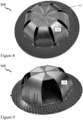
- FIG. 8 there is depicted a photograph 800 of a GNSS antenna according to an embodiment of the invention employing 8 petals within the array of petals.
- a circular Disk 910 of metallization is patterned on the substrate of the array of petal elements.
- the Disk 910 being at the center between each pair of opposed petal elements and is a common center for all opposed petal pairs.
- the metallized Disk 910 provides a controlled capacitance to a virtual ground, by virtue of the antipodal voltages present at the narrow petal tips of the Petal Elements 110.
- This Disk 910 is also visible within the views of GNSS antenna and arrays of Petal 110 depicted in Figures 1B , 7A , and 7C-7D respectively but was not identified explicitly within the descriptions of these Figures.
- FIG. 10 there is depicted a photograph 900 a GNSS antenna according to an embodiment of the invention employing 4 Petals 110 within the array of petals. This being the minimum configuration of Petals 110 for a GNSS antenna employing a pair of orthogonal dipoles.
- FIGS 10A and 10B there are depicted a plan perspective schematic 1000A and photograph 1000B respectively of an array of petals for a GNSS antenna according to an embodiment of the invention employing 4 petals.
- the Petals 110 are evident together with Tabs 130.
- the metallization is depicted as shaded regions forming the Petals 110 and accordingly it is evident that there is no overall pattern of metallization on the Tabs 130 but rather discrete Solder Pads 1010.
- Photograph 1000B depicts a 4 Petal 110 array where there are no tabs at the distal ends of the Petals 110 from the center of the array.
- FIG 11 there is depicted a plan perspective schematic of a pair of petals for an antenna according to an embodiment of the invention employing a pair of Petals 110 where in common with schematic 1000A each Petal 110 has a pair of Tabs 130 with Solder Pads 1010 disposed at its distal end.
- the pair of Petals 110 depicted in Figure 11 being, for example, the pair of petals depicted in the cross-sectional view 1300A in Figure 13 as described above which are coupled to a single dipole.
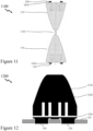
- FIG. 12 there is depicted a schematic 1200 for an alternate configuration of a Petal 1310 and Tab 130 for use within a GNSS antenna according to an embodiment of the invention.
- the Tabs 130 are metallized with first Metallization 1320 bur rather than discrete metallization per tab the first Metallization 1320 is now continuous across the distal end of the Petal 1310.
- this first Metallization 1320 is electrically isolated from the second Metallization 1330 which provides the petal in conjunction with the carrier 1310 upon which the first and second Metallizations 1320 and 1330 are formed.
- the Tabs 130 project through openings within the PCB 120 wherein the first Metallization 1320 would be connected to the ground plane of the PCB 120.
- the Petals 110 have been primarily described and depicted as being upon a carrier / substrate (hereinafter referenced to as a former) where the Petals 110 are evenly distributed around the periphery of the former.
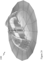
- This former is depicted as forming essentially a truncated hemispherical surface.
- the former may be designed and formed to provide different physical geometries such as a frusto-conical surface and the Petals 110 are distributed around this frusto-conical surface.
- the former may be designed and formed to provide the Petals 110 evenly distributed around the periphery of a polygonal surface and form the antennas across this polygonal surface.
- Such a polygonal surface may have 4, 5, 6, 7, 8, etc. sides or other numbers although typically more sides yield lower angular transitions and hence induced stress and/or fatigue.
- Embodiments of the invention described and depicted in respect of Figures 1A-15 employ a PCB 120.
- the PCB may be fabricated on a low loss substrate such as a glass-reinforced epoxy laminate material, glass ceramic composite laminate or a ceramic composite laminate for example.
- the PCB substate selecting providing the requisite performance of the microwave/RF elements and circuits of the Electronics 140 and tracks coupling to Dipole A 220 and Dipole B 230.
- the GNSS antenna frequencies may provide constraints on the PCB size.
- the PCB 120 is circular in shape and approximately 110mm in diameter with one or more metallized layers.
- Features such as ground vias and mounting holes, such as for the Tabs 130 for example, may be formed in the PCB 120.
- the ground plane of the GNSS antenna within embodiments PCB 120 may be fabricated within a two or more layer PCB 120 with the surface proximate to the installed antenna structure fully covered with metallization to provide a reflective microwave surface for the dipoles and petals disposed above.
- This metallization acts as a reflective ground plane as commonly used in GNSS antennas and provides the ability to increase the radiated gain "above” the antenna element, simultaneously reducing the radiated gain "below” the ground plane.
- each Petal was formed by patterned metallization upon a semi-flexible substrate, such as a glass-reinforced epoxy laminate material, glass ceramic composite laminate or a ceramic composite laminate for example which is thin, for example less than 0.2mm thick (0.008").
- a semi-flexible substrate such as a glass-reinforced epoxy laminate material, glass ceramic composite laminate or a ceramic composite laminate for example which is thin, for example less than 0.2mm thick (0.008").
- Each metallized Petal 110 being a two dimensional shape with a wider, outer end and a central, narrower end with a central axis longer than the wider end, with progressively decreasing width between the wider end and the narrow end.
- a pair of Petals 110 within each opposed pair is comprised of a first Petal 110 and a second Petal 110, co-linear with the first Petal 110, and of identical dimensions, with the proximate ends of first and second Petals 110 being the narrower ends with the midpoint between first and second Petals 110, mirrored around an axis, on the extended common axis defined as the geometric antenna center.
- a plurality of metallized petal pairs are located such that the midpoint of each petal pair is located at the antenna center, with a relative rotation angle between adjacent for petal pairs equal for all petal pairs and equal to 360 degrees divided by 2N, where N is the number metallized petal pairs in the implementation.
- N is the number metallized petal pairs in the implementation.
- each Petal is formed via the upper edges of Dipole A 220 and Dipole B 230 to a surface defining a substantially hemispherical shape.
- the upper surfaces of the first to fourth Supports 210A to 210D respectively defining a similar surface to that of Dipole A 220 and Dipole B 230.
- the surface defined by these surfaces to be a different shape although the performance of the GNSS antenna may be different.
- the mechanical assembly provides for the pair of orthogonal dipoles to not only be orthogonally disposed relative to one another but for these to be disposed perpendicular to the plane of the PCB. Accordingly, if we consider Dipole A 220 as being aligned to an X-axis then it is positioned in the X-Z plane and Dipole B 230 is aligned/position with respect to the Y-Z plane.
- each Petal 110 has Tabs 130 at its distal end from the centre of the antenna. These being metallized in the embodiment of the invention described and depicted such that in the assembled GNSS antenna the semi-flexible PCB is installed onto the dipole structure and the ground plane of PCB 120 by means of this metallization. As depicted in Figure 12 the metallized tabs are connected to a thin metallized track parallel to the wider edge of the metallized petal on the semiflexible PCB 700. This thin metallized track being electrically isolated from the metallized petal by a narrow unmetallized spacing.
- the separation of the petal and ground plane is important in several respects. Firstly, current flow associated with the RF wave transmitted or received is largely conducted along the edge of the metallized petals, thus creating a microwave slot between the ground plane and petal. Acting as a transmission line the slot guides the RF wave resulting in a current flow null at the center of the wider edge, and is effective to reduce the low frequency response. Secondly, the capacitance between the ground plane and the petal is dominated by the unmetallized gap, which has precisely defined dimensions by virtue of the precision of the PCB fabrication process allowing the capacitance to be accurately defined. Whilst other mechanical assembly methodologies may be employed for attaching / positioning the Petals 110 then these must consider this capacitance and its variation within their design and manufacturing tolerances.
- the variation of the unmetallized gap dimensions and hence transmission line impedance provides a convenient means to tune the effective patch length at the lower frequencies for the GNSS antenna. Accordingly, the gap may be established in dependence upon a tuning to be applied to frequencies below a predetermined frequency. Fourthly, the decreased capacitance at the base of the petal (increased reactance) is effective to increase the natural frequency of the petal as a monopole, thereby increasing the frequency of any a common mode (monopole) resonance well beyond the upper receive band edge. Finally, the unmetallized gap is effective at least in part to reduce coupling for ground plane current onto the petals.
- the outside dimensions of the semi-flexible PCB may be larger than the circle of slots within which the Tabs 130 are assembled so that the semi-flexible PCB, when assembled over the two dipoles (Dipole A 220 and Dipole B 230) and secured to the ground plane of PCB 120 conforms to the shape of the upper surface of the two dipole PCBs. As such these may define a hemispherical dome.
- each of the metallized Petals 110 curves upwards from their wider end, secured to the ground plane of PCB 120, towards their narrow end, at a point above the antenna center at a height pre-determined by the structure dimensions of the GNSS antenna components.
- the semi-flexible substrate PCB of a dual metallized petal pair is designed with a central region concentric with the antenna center.
- the central region may be an octagonal shape dimensioned as a regular octagon with approximately across the flats. This central region may be dimensioned to match that of a stiffener, e.g. Support Frame 310.
- a stiffener e.g. Support Frame 310.
- the first to fourth Supports 210A to 210D may be optionally removed, especially if the semi-flexible PCB is only present where the Petals 110 are implemented.
- the first to fourth Supports 210A to 210D respectively ensure that the Petals 110 disposed between Petals 110 associated with the pair of dipoles have the same surface profile.
- the metallization of the Petals 110 is pattern with slots which within the assembled GNSS antenna are vertical to the ground plane of the GNSS antenna.
- the design goal of the inventors was a precision GNSS antenna with a broad bandwidth, a good AR, and a very tight phase centre variation with improved performance for the reception of signals from satellites at low elevation angles. This being particularly necessary for reception of L-band correction signals which can be expected to be incident at elevation angles of 10 degrees to 50 degrees above the horizon.
- the DM antenna has been employed for decades in GPS reference stations (usually employed within a choke ring antennas).
- the DM antenna exhibits a higher gain at low elevation angles (about -3 dBic at horizon) than that of other GNSS antennas commercially available (typically -5 dBic or less), and a fairly good phase-center stability in a compact design.
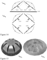
- the DM antenna structure consists of two orthogonal pairs of short dipoles above a ground plane, with the feeds at the midpoint of the dipoles, as shown in first image 1400A in Figure 14A. As depicted there is first Dipole 1410 with its feed 1415 and second Dipole 1420 with its associated feed 1425. These being disposed above the ground plane 1430.
- the antenna can be considered in terms of a ground plane image, replacing the ground plane 1430 with the images of the dipoles.
- third dipole 1440 represents the image of first dipole 1410A and fourth dipole 1450 the image of second dipole 1420.
- the DM antenna exhibits drawbacks in that the feed network is complex and lossy with costly fabrication, which affects repeatability and reliability. Further, the AR at zenith is marginal (up to 1.5 dB) and further degrades to 7 dB at the horizon, a factor that become less relevant in a choke ring configuration where the DM antenna is the most commonly used.
- the GNSS antenna consists of bowtie radiator elements (the petals) which are disposed over a circular ground plane.
- the petals are coupled to a distributed feed network comprising the pair of low loss crossed dipoles located between the petals and the ground plane, namely Dipole A 220 and Dipole B 230 as described and depicted in Figures 2-6B and 8 respectively.
- the relationship between the petals and the associated feed system provides a current maximum at the curvature of the petals instead of at the center of the antenna.
- the inventors have established that the circular polarization of the antenna at low elevation angles can be significantly improved by optimizing the petal's dimensions such as its height, width, and its angle with respect to the ground plane. These geometric adjustments can address the problem of asymmetry between the E and H planes of the antenna radiation pattern, which usually degrades the AR at low elevation angles. Based upon the simulations the inventors established that the bowtie geometry of the radiators (petals), as well as their coupling to the feeding network, can improve both the impedance and AR bandwidth of the GNSS antenna. In this manner the inventors have established a wideband, low loss antenna covering the entire GNSS frequencies from 1150 MHz to 1610 MHz.
- Exemplary performance for which more details are presented in Section 4, being that the matching loss to the feeding network is below 0.3 dB, the AR remains around 0.5 dB at zenith and the AR is typically below 3 dB at horizon over the whole GNSS frequency range.
- the GNSS antenna has 4 petals whilst in Figures 1A-2B, 7A-9 and 15A there are 8 petals.
- the inventors established that increasing the number of petals resulting in improvements in symmetry, but at the cost of complexity. Accordingly, the exemplary embodiments of the invention depicted in Figures 9-10B employ the minimum 4 whilst those within Figures 1A-2B, 7A-9 and 15A exploit 8 as this was established as a balance between the improved symmetry relative to 4 petals and feed complexity.
- the GNSS antenna receives/radiates RF signals by means of electromagnetic radiation resulting from currents induced/driven into diametrically opposed "petals pairs" disposed in a piecewise linear approximation to a curved 3-dirmensional structure above a metal ground plane.
- the received/radiated signals from the GNSS antenna being coupled from/to a petal pair by a dipole coupled to the microwave/RF feed network.
- a GNSS antenna employs a pair of such dipoles which are disposed orthogonal to one another and have high electromagnetic isolation from one to the other. If signals of the same frequency but having a 90 degree phase difference ("phase quadrature") are imposed upon the orthogonal, electrically isolated antennas, the resulting radiation is circular because the two signals can be considered unrelated except to say that the resultant radiated signal is the vector sum of the radiating electric vectors is a vector rotating in space.
- phase quadrature phase difference
- Each single opposed petal pair structure exhibits two operational modes in the frequency band of interest.
- the first mode a wanted mode, is one in which the currents in each of the opposed petals flow in phase, Consequentially, the voltages developed across each of the petals are also in phase, so that at the at the extremities of the petal pair the voltages are antipodal, with a maximum electromagnetic field generated between the narrow ends at the antenna center which arises due to the low impedance at the wider end of the petals resulting from the image/capacitance adjacent to the ground plane.
- the second move, an unwanted mode is a form of cavity or monopole resonance, wherein the entire cavity or collection of monopoles, exhibits a lambda/4 resonance.
- the voltages produced at the "top" of the monopoles are in phase and accordingly there is no potential difference between the narrower ends of the petals at the center.
- specific consideration of this resonant mode is not addressed as the frequency of this resonant mode can be moved to a higher frequency outside of the band of interest by parametric adjustments to the GNSS antenna.
- each opposed petal pair may be viewed as operating as one half of a structure known as the Alford Loop in that in the first mode the currents in each of the opposed petals flow in phase (as do the currents within the pair of dipoles comprising first Dipole 1410 and second Dipole 1420 in Figure 14B). Accordingly, in conjunction with the ground plane and the mirror images of these currents flowing an effective Alfred Loop is established.
- a plane wave incident on the GNSS antenna at the horizon such that the Poynting vector is aligned with the axis of the first opposed petal pair (e.g. an electromagnetic field aligned with a vertical E field and horizontal H field) will induce a current in the first opposed petal pair (orthogonal to the H field), and an EM wave aligned with a horizontal E field and vertical H field will be generate an electromagnetic field in the second opposed petal pair (parallel to the E field).
- This structure is favorable for low axial ratio by virtue of potentially balanced signals induced/generated in orthogonal opposed petal pairs by orthogonal fields.
- each petal varies from a low value close to the wider end of the petal, located close to the edge of the ground plane, to a very high value at the narrow end of the petal near to the antenna center.
- the feed impedance at the wider end of the petals is low, similar to that of a monopole (around 25 Ohms), then further reduced by currents arising from the reflected image of the curved monopole over the ground plane.
- this impedance can be matched so that a directly connected feed to the wider end of each petal is electrically and mechanically convenient.
- the feed return currents are also directly injected into the ground plane.
- the ground plane is close to lambda/2 in diameter, and driven currents flowing in the ground plane cause the ground plane itself to radiate, which very significantly interferes with and degrades the wanted radiation characteristics.
- Measurements and simulations performed by the inventors confirmed that the ground return currents associated with the "monopole" style petal feeds result in poor axial ratios, particularly at low elevation angles.
- a direct connection at the center of the structure, namely each petal is fed at the narrower end, is characterized by a high impedances, which is difficult to match.
- the inventive GNSS antenna avoids these difficulties associated with direct electrical connections of feed circuits by using the pair of dipoles (narrow band dipoles) which form X-Y axes around a centre point of the ground plane, e.g. formed as part of the PCB 120 or alternatively separate to it.
- the pair of dipoles namely Dipole A 220 and Dipole B 230, are arranged above the ground plane of the PCB and are coupled to the feed circuit.
- Above the pair of orthogonally disposed dipoles are a plurality of petal pairs arranged such that the pair of dipoles are aligned along a centre line of each a petal pair of the plurality of petal pairs.
- the plurality of petal pairs is arrayed circularly around a z-axis orthogonal to a plane formed by the ground plane.
- the z-axis passes through the centre of the ground plane.
- the plurality of petal pairs is disposed such that the mid-point of each petal pair, namely the midpoint between the metallized petals, is precisely located at the antenna centre at the crossing point of the pair of dipoles.
- An outer end of each of the plurality of petal pairs is secured, for example to an outer circumference of the ground plane.
- a GNSS antenna comprises a number of components:
- the plurality of pairs of petals are disposed as a substantially hemispherical, domed array of opposed metallized petal pairs. These may be mounted to the ground plane in proximity to the outer circumference of the ground plane.
- the distributed feed network couples the opposed metallized petal pairs to an electrical circuit and provides the progressive relative phase shifts to enable operation of the GNSS antenna upon circular polarization.
- the inventors have established an innovative wideband antenna structure comprising a narrow band dipole coupled electromagnetically to a symmetrical arrangement of metallized petals which are arranged centrally over a distal metallized ground plane, with symmetrical antipodal feed signals connected to the dipole feed connections at the center of the dipole, wherein the innovative wideband antenna structure provides a wideband return loss and impedance at the dipole feed connections.
- This performance comparable to that of the narrow band return loss of the dipole alone wherein the metallized petals provide a wideband loss matching feed network to increase the radiative efficiency of the combined structure.
- the inventors have established an innovative wideband antenna structure comprising a dipole coupled electromagnetically to a symmetrical arrangement of metallized petals, arranged centrally over a distal metallized ground plane, with symmetrical antipodal feed signals connected to the dipole feed connections at the center of the dipole which are further connected to feed connections confined toward the center of the ground plane, whereby local current maxima in the antenna radiating elements are offset from the dipole center, and a ground plane remains essentially devoid of dipole feed return currents where the dipole and symmetrical arrangement of metallized petals are disposed above the ground plane.
- the inventors have established an innovative wideband antenna structure comprising a narrow band dipole coupled electromagnetically to a symmetrical arrangement of metallized petals, arranged centrally over a distal metallized ground plane, with symmetrical antipodal feed signals connected to the dipole feed connections at the center of the dipole, wherein local current maxima in the antenna radiating elements are offset from the dipole center and an inflexion in the magnitude of the current in the combined radiating elements comprising the dipole and symmetrical arrangement of metallized petals occurs at the center of the dipole.
- the inventors have established an innovative wideband antenna structure comprising a narrow band dipole coupled electromagnetically to a symmetrical arrangement of metallized petals, arranged centrally over a distal metallized ground plane, with symmetrical antipodal feed signals connected to the dipole feed connections at the center of the dipole, wherein the symmetrical metallized petals extend the bandwidth of the antenna structure to larger than that of the narrow band dipole alone.
- GNSS antenna according to an exemplary embodiment of the invention.
- the GNSS antenna being as depicted in first image 1500 in Figure 15A.
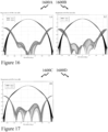
- the measured radiation patterns for the exemplary GNSS antenna are presented in Figures 16 and 17 at four different GPS frequencies. These being:
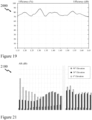
- Figure 18 there is depicted a comparison of a GNSS antenna according to an embodiment of the invention (GNSS Invention) with 6 commercial rover prior art GNSS antennas targeted to the same application (GNSS 1 to GNSS 6). Accordingly, it is evident that the GNSS antenna according to an embodiment of the invention has a significantly lower roll-off than the prior art antennae. As evident from Figure 18 the amplitude roll-off for the GNSS antenna according to an embodiment of the invention from boresight (zenith) to horizon is between 6.5-8 dB for all the frequency bands.
- Multipath signals are mainly late LHCP and RHCP. If they arrive at high elevation angles, there is no issue as the AR of the antenna is low at those angles, thus there will be minimal reception of the multipath signals.
- low elevation angle multipath degrades observations due to the poor AR performance and low UDR.
- the GNSS antenna according to an embodiment of the invention provides for improved AR performance and good UDR, which significantly reduces multipath interference. Accordingly, the inventors also performed measurements in a high multipath environment for the GNSS antenna according to an embodiment of the invention and the 6 commercial rover prior art GNSS antennae.
- the GNSS antenna according to an embodiment of the invention yielded a phase noise at 5° degrees elevation angle of approximately 6 mm to 10 mm over all GNSS frequencies. Whilst the other prior art GNSS antennae performed similarly they have higher roll-off and hence lower gain at the horizon. Accordingly, the GNSS antenna according to an embodiment of the invention provides stronger signals at low elevation angles and improved multipath mitigation performance relative to the prior art antennae.
- FIG 19 there is depicted the right hand circular polarisation (RHCP) gain of a GNSS antenna according to an embodiment of the invention at zenith and 10° elevation for all GNSS frequencies.
- RVCP right hand circular polarisation
- the AR values of the GNSS antenna according to an embodiment of the invention different elevation angles are shown in Figure 21 .
- the GNSS antenna according to an embodiment of the invention has good AR performance over the all GNSS frequency bands and at all elevation angles and does not exceed 3.5 dB. It is known that a low AR increases an antenna's ability to reject the LHCP signals that are caused by the reflections from nearby objects. Accordingly, the susceptibility of a GNSS antenna according to an embodiment of the invention to multipath interference is greatly reduced.
- the AR performance of the GNSS antenna according to an embodiment of the invention at horizon is compared to the 6 commercial rover GNSS prior art antennae.
- the GNSS antenna according to an embodiment of the invention has the lowest AR among these antennas.
- the lowest AR of these competitive antennas being comparable to the worst AR of the GNSS antenna according to an embodiment of the invention, but typically significantly higher AR is evident for the commercial GNSS antennae relative to the GNSS antenna according to an embodiment of the invention.
- Figure 23 depicts the maximum PCV of the GNSS antenna according to an embodiment of the invention relative to the six commercial rover antennas for four common GNSS frequencies. It is evident from Figure 23 that the GNSS antenna according to an embodiment of the invention has a maximum total PCV of less than 2.9 mm for all frequency bands, results being depicted for GPS L1, GPS L2, GPS L5 and Galileo E6. Further, the PCV of the GNSS antenna according to an embodiment of the invention does not vary significantly with frequency.
- CNR or C/N carrier-to-noise ratio
- G/T ratio parameter
- the received signal from the GNSS antenna according to an embodiment of the invention is split by a diplexer directly connected to the antenna terminals into two bands, one comprising the lower GNSS frequencies (from 1160 MHz to 1300 MHz) and the other the higher GNSS frequencies (from 1539 MHz to 1610 MHz). Each band is then pre-filtered.
- GNSS receivers must accommodate a crowded RF spectrum, and there are a number of high-level, potentially interfering signals that can saturate and desensitize GNSS receivers. These include, for example, the Industrial Scientific and Medical (ISM) band signals and mobile phone signals, particularly Long-Term Evolution (LTE) signals in the 700-MHz band, which are a hazard because of the potential for harmonic generation in the GNSS LNA.
- ISM Industrial Scientific and Medical
- LTE Long-Term Evolution
- Other potential interfering signals include Globalstar (1610 MHz to 1618.25 MHz), Iridium (1616 MHz to 1626 MHz) and Inmarsat (1626 MHz to 1660.5 MHz) which are high-power uplink signals and particularly close in frequency to GLONASS signals.
- the LNA implemented by the inventors for use with the GNSS antenna according to an embodiment of the invention is a compromise between ultimate sensitivity and ultimate interference rejection.
- a first defense is the addition of multi-element bandpass filters at the antenna element terminals (ahead of the LNA). These have a typical insertion loss of 1 dB because of their tight passband and steep rejection characteristics but the LNA noise figure is increased approximately by the additional filter-insertion loss.
- the second defensive measure is to employ a high linearity LNA which is achieved without any significant increase in LNA power consumption, using LNA chips that employ negative feedback to provide well controlled impedance and gain over a very wide bandwidth.
- the filters in the LNA established by the inventors yields a maximum variation of less than 10 nanoseconds in group delay over the lower GNSS frequencies (from 1160 MHz to 1300 MHz) and over the higher GNSS frequencies (from 1539 MHz to 1610 MHz) respectively.
- the inventors have established two variants of the LNA, one with 28 dB gain LNA which is embedded within the Electronics 140 of microwave/RF circuit of the GNSS antenna and a second with 37 dB LNA intended for use in installations with long coaxial cable runs.
- the microwave/RF circuit within the Electronics 140 of the GNSS Antenna is internally regulated to allow a supply voltage from 3 V to 16 V.
Landscapes
- Engineering & Computer Science (AREA)
- Radar, Positioning & Navigation (AREA)
- Remote Sensing (AREA)
- Signal Processing (AREA)
- Computer Networks & Wireless Communication (AREA)
- Physics & Mathematics (AREA)
- General Physics & Mathematics (AREA)
- Variable-Direction Aerials And Aerial Arrays (AREA)
- Details Of Aerials (AREA)
Applications Claiming Priority (3)
| Application Number | Priority Date | Filing Date | Title |
|---|---|---|---|
| US201962900605P | 2019-09-15 | 2019-09-15 | |
| PCT/CA2020/051188 WO2021046635A1 (fr) | 2019-09-15 | 2020-08-31 | Systèmes, éléments et procédés d'antenne gnss |
| EP20864163.9A EP4032146B1 (fr) | 2019-09-15 | 2020-08-31 | Systèmes, éléments et procédés d'antenne gnss |
Related Parent Applications (2)
| Application Number | Title | Priority Date | Filing Date |
|---|---|---|---|
| EP20864163.9A Division EP4032146B1 (fr) | 2019-09-15 | 2020-08-31 | Systèmes, éléments et procédés d'antenne gnss |
| EP20864163.9A Division-Into EP4032146B1 (fr) | 2019-09-15 | 2020-08-31 | Systèmes, éléments et procédés d'antenne gnss |
Publications (2)
| Publication Number | Publication Date |
|---|---|
| EP4572016A2 true EP4572016A2 (fr) | 2025-06-18 |
| EP4572016A3 EP4572016A3 (fr) | 2025-08-13 |
Family
ID=74866638
Family Applications (2)
| Application Number | Title | Priority Date | Filing Date |
|---|---|---|---|
| EP20864163.9A Active EP4032146B1 (fr) | 2019-09-15 | 2020-08-31 | Systèmes, éléments et procédés d'antenne gnss |
| EP25171367.3A Pending EP4572016A3 (fr) | 2019-09-15 | 2020-08-31 | Systèmes, éléments et procédés d'antenne gnss |
Family Applications Before (1)
| Application Number | Title | Priority Date | Filing Date |
|---|---|---|---|
| EP20864163.9A Active EP4032146B1 (fr) | 2019-09-15 | 2020-08-31 | Systèmes, éléments et procédés d'antenne gnss |
Country Status (6)
| Country | Link |
|---|---|
| US (2) | US12046841B2 (fr) |
| EP (2) | EP4032146B1 (fr) |
| CN (1) | CN114600318B (fr) |
| CA (1) | CA3154668A1 (fr) |
| ES (1) | ES3049107T3 (fr) |
| WO (1) | WO2021046635A1 (fr) |
Families Citing this family (17)
| Publication number | Priority date | Publication date | Assignee | Title |
|---|---|---|---|---|
| JP7493962B2 (ja) * | 2020-03-04 | 2024-06-03 | キヤノン株式会社 | アンテナ |
| WO2022188946A1 (fr) * | 2021-03-08 | 2022-09-15 | Telefonaktiebolaget Lm Ericsson (Publ) | Élément rayonnant dipolaire, dipôle croisé à double polarisation comprenant deux éléments rayonnants dipolaires et antenne de communication mobile comprenant une pluralité de dipôles croisés à double polarisation |
| US11990677B2 (en) * | 2021-03-12 | 2024-05-21 | Raytheon Company | Orthogonal printed circuit board interface |
| US20230054135A1 (en) * | 2021-08-23 | 2023-02-23 | Te Connectivity Solutions Gmbh | Omnidirectional antenna assemblies including broadband monopole antennas |
| CN113851816B (zh) * | 2021-09-13 | 2024-03-12 | RealMe重庆移动通信有限公司 | 天线组件和电子设备 |
| DE102021128221B4 (de) | 2021-10-29 | 2023-07-27 | Deutsches Zentrum für Luft- und Raumfahrt e.V. | Antennensystem für den Empfang von Signalen von einer Sendeantenne |
| WO2023087099A1 (fr) * | 2021-11-16 | 2023-05-25 | Gyles Panther | Dispositifs d'antenne à large bande et à profil bas et procédés |
| US12244069B2 (en) * | 2022-06-07 | 2025-03-04 | Aeroantenna Technology, Inc. | Cross dipole circularly polarized antenna |
| US11719732B1 (en) | 2022-07-25 | 2023-08-08 | Divirod, Inc. | Reflectometer sensor |
| EP4537424A4 (fr) * | 2022-08-08 | 2025-10-08 | Calian Gnss Ltd | Structures d'antenne filaire à éléments multiples |
| CN115513637B (zh) * | 2022-09-27 | 2025-03-07 | 江苏屹信航天科技有限公司 | 一种s频段卫星天线 |
| CN115765767A (zh) * | 2022-10-24 | 2023-03-07 | 华南理工大学 | 一种应用于通信感知一体化的毫米波集成系统 |
| US12392904B2 (en) * | 2023-01-16 | 2025-08-19 | Rockwell Collins, Inc. | Controlled radiation pattern antenna for jamming/spoofing resistant airborne GNSS sensors |
| CN116073120A (zh) * | 2023-03-06 | 2023-05-05 | 安徽大学 | 一种宽带毫米波圆极化天线单元、单模阵列及双模阵列 |
| CN117175195B (zh) * | 2023-03-16 | 2024-04-12 | 广州程星通信科技有限公司 | 一种宽带广角扫描的双圆极化天线阵列 |
| US20240349262A1 (en) * | 2023-04-12 | 2024-10-17 | Qualcomm Incorporated | L-band frequency domain resource allocation |
| WO2025065110A1 (fr) * | 2023-09-29 | 2025-04-03 | Julien Hautcoeur | Procédés, systèmes et éléments pour antennes gnss |
Family Cites Families (9)
| Publication number | Priority date | Publication date | Assignee | Title |
|---|---|---|---|---|
| WO2006118496A1 (fr) | 2005-04-29 | 2006-11-09 | Telefonaktiebolaget Lm Ericsson (Publ) | Antenne en forme de trefle a triple polarisation dotee de dipoles |
| US8723731B2 (en) * | 2008-09-25 | 2014-05-13 | Topcon Gps, Llc | Compact circularly-polarized antenna with expanded frequency bandwidth |
| EP2569824B1 (fr) * | 2010-05-13 | 2019-03-13 | UTI Limited Partnership | Antenne polarisée circulairement à caractéristiques large bande |
| US8570233B2 (en) * | 2010-09-29 | 2013-10-29 | Laird Technologies, Inc. | Antenna assemblies |
| US8466846B1 (en) * | 2010-09-29 | 2013-06-18 | Rockwell Collins, Inc. | Ultra wide band balanced antipodal tapered slot antenna and array with edge treatment |
| US10770803B2 (en) * | 2017-05-03 | 2020-09-08 | Commscope Technologies Llc | Multi-band base station antennas having crossed-dipole radiating elements with generally oval or rectangularly shaped dipole arms and/or common mode resonance reduction filters |
| US10530068B2 (en) * | 2017-07-18 | 2020-01-07 | The Board Of Regents Of The University Of Oklahoma | Dual-linear-polarized, highly-isolated, crossed-dipole antenna and antenna array |
| CN109301469B (zh) * | 2018-10-24 | 2019-10-25 | 西安电子科技大学 | 一种基于强耦合效应的宽频带圆极化天线 |
| US12244069B2 (en) * | 2022-06-07 | 2025-03-04 | Aeroantenna Technology, Inc. | Cross dipole circularly polarized antenna |
-
2020
- 2020-08-31 WO PCT/CA2020/051188 patent/WO2021046635A1/fr not_active Ceased
- 2020-08-31 US US17/753,800 patent/US12046841B2/en active Active
- 2020-08-31 EP EP20864163.9A patent/EP4032146B1/fr active Active
- 2020-08-31 EP EP25171367.3A patent/EP4572016A3/fr active Pending
- 2020-08-31 CA CA3154668A patent/CA3154668A1/fr active Pending
- 2020-08-31 CN CN202080070463.9A patent/CN114600318B/zh active Active
- 2020-08-31 ES ES20864163T patent/ES3049107T3/es active Active
-
2024
- 2024-06-07 US US18/737,439 patent/US20240332808A1/en active Pending
Also Published As
| Publication number | Publication date |
|---|---|
| CN114600318A (zh) | 2022-06-07 |
| WO2021046635A1 (fr) | 2021-03-18 |
| ES3049107T3 (en) | 2025-12-15 |
| US20240332808A1 (en) | 2024-10-03 |
| EP4032146B1 (fr) | 2025-09-24 |
| US20220344823A1 (en) | 2022-10-27 |
| EP4032146A4 (fr) | 2023-10-11 |
| EP4032146A1 (fr) | 2022-07-27 |
| CA3154668A1 (fr) | 2021-03-18 |
| CN114600318B (zh) | 2025-11-04 |
| EP4032146C0 (fr) | 2025-09-24 |
| US12046841B2 (en) | 2024-07-23 |
| EP4572016A3 (fr) | 2025-08-13 |
Similar Documents
| Publication | Publication Date | Title |
|---|---|---|
| EP4032146B1 (fr) | Systèmes, éléments et procédés d'antenne gnss | |
| US6847328B1 (en) | Compact antenna element and array, and a method of operating same | |
| Massa | A dual frequency microstrip patch antenna for high-precision GPS applications | |
| US7385555B2 (en) | System for co-planar dual-band micro-strip patch antenna | |
| US6836247B2 (en) | Antenna structures for reducing the effects of multipath radio signals | |
| US8842045B2 (en) | Compact multipath-resistant antenna system with integrated navigation receiver | |
| EP3095155B1 (fr) | Système mondial d'antenne de navigation par satellites ayant un noyau creux | |
| US8307535B2 (en) | Multi-frequency antenna manufacturing method | |
| KR20080039901A (ko) | 위성 측위 시스템을 위한 다중 밴드 안테나 | |
| US12113304B2 (en) | Stacked patch antenna devices and methods | |
| US11165167B2 (en) | Antenna system for circularly polarized signals | |
| AU2006272392A1 (en) | Leaky wave antenna with radiating structure including fractal loops | |
| CN113851863A (zh) | 基于弯折阵子的小型化宽波束多频融合收发一体北斗天线 | |
| CN107611606B (zh) | 天线结构和终端 | |
| CN113169456A (zh) | 宽带gnss天线系统 | |
| Rohrdantz et al. | Ka-band antenna arrays with dual-frequency and dual-polarized patch elements | |
| US20250007169A1 (en) | Broadband low profile antenna devices and methods | |
| Chen et al. | Antennas for global navigation satellite system receivers | |
| Kraanthi et al. | Circularly polarized dual band stacked patch antenna for satellite navigation applications | |
| Murugan et al. | Design of wideband circularly polarized capacitive fed microstrip antenna | |
| Tombakdjian et al. | GNSS high performance antenna system using phased array technique | |
| Liang et al. | Design and Improvement Methodology of Super Compact Dual-Band Dual-Circularly Polarized Antennas for UHF/VHF Satellite IoT Communication |
Legal Events
| Date | Code | Title | Description |
|---|---|---|---|
| PUAI | Public reference made under article 153(3) epc to a published international application that has entered the european phase |
Free format text: ORIGINAL CODE: 0009012 |
|
| STAA | Information on the status of an ep patent application or granted ep patent |
Free format text: STATUS: THE APPLICATION HAS BEEN PUBLISHED |
|
| AC | Divisional application: reference to earlier application |
Ref document number: 4032146 Country of ref document: EP Kind code of ref document: P |
|
| AK | Designated contracting states |
Kind code of ref document: A2 Designated state(s): AL AT BE BG CH CY CZ DE DK EE ES FI FR GB GR HR HU IE IS IT LI LT LU LV MC MK MT NL NO PL PT RO RS SE SI SK SM TR |
|
| REG | Reference to a national code |
Ref country code: DE Ref legal event code: R079 Free format text: PREVIOUS MAIN CLASS: H01Q0021200000 Ipc: H01Q0021260000 |
|
| PUAL | Search report despatched |
Free format text: ORIGINAL CODE: 0009013 |
|
| P01 | Opt-out of the competence of the unified patent court (upc) registered |
Free format text: CASE NUMBER: APP_30302/2025 Effective date: 20250624 |
|
| AK | Designated contracting states |
Kind code of ref document: A3 Designated state(s): AL AT BE BG CH CY CZ DE DK EE ES FI FR GB GR HR HU IE IS IT LI LT LU LV MC MK MT NL NO PL PT RO RS SE SI SK SM TR |
|
| RIC1 | Information provided on ipc code assigned before grant |
Ipc: H01Q 21/26 20060101AFI20250709BHEP Ipc: G01S 19/36 20100101ALI20250709BHEP Ipc: H01Q 9/28 20060101ALI20250709BHEP Ipc: H01Q 25/00 20060101ALI20250709BHEP Ipc: H01Q 21/20 20060101ALI20250709BHEP |
|
| STAA | Information on the status of an ep patent application or granted ep patent |
Free format text: STATUS: REQUEST FOR EXAMINATION WAS MADE |
|
| 17P | Request for examination filed |
Effective date: 20250826 |