EP4572002A1 - Batteriezelle, batterie, elektrische vorrichtung, schweissverfahren und vorrichtung - Google Patents
Batteriezelle, batterie, elektrische vorrichtung, schweissverfahren und vorrichtung Download PDFInfo
- Publication number
- EP4572002A1 EP4572002A1 EP22962980.3A EP22962980A EP4572002A1 EP 4572002 A1 EP4572002 A1 EP 4572002A1 EP 22962980 A EP22962980 A EP 22962980A EP 4572002 A1 EP4572002 A1 EP 4572002A1
- Authority
- EP
- European Patent Office
- Prior art keywords
- welding
- weld
- seal
- segment
- pulsed laser
- Prior art date
- Legal status (The legal status is an assumption and is not a legal conclusion. Google has not performed a legal analysis and makes no representation as to the accuracy of the status listed.)
- Pending
Links
Images



Classifications
-
- H—ELECTRICITY
- H01—ELECTRIC ELEMENTS
- H01M—PROCESSES OR MEANS, e.g. BATTERIES, FOR THE DIRECT CONVERSION OF CHEMICAL ENERGY INTO ELECTRICAL ENERGY
- H01M50/00—Constructional details or processes of manufacture of the non-active parts of electrochemical cells other than fuel cells, e.g. hybrid cells
- H01M50/60—Arrangements or processes for filling or topping-up with liquids; Arrangements or processes for draining liquids from casings
- H01M50/609—Arrangements or processes for filling with liquid, e.g. electrolytes
- H01M50/627—Filling ports
- H01M50/636—Closing or sealing filling ports, e.g. using lids
-
- B—PERFORMING OPERATIONS; TRANSPORTING
- B23—MACHINE TOOLS; METAL-WORKING NOT OTHERWISE PROVIDED FOR
- B23K—SOLDERING OR UNSOLDERING; WELDING; CLADDING OR PLATING BY SOLDERING OR WELDING; CUTTING BY APPLYING HEAT LOCALLY, e.g. FLAME CUTTING; WORKING BY LASER BEAM
- B23K26/00—Working by laser beam, e.g. welding, cutting or boring
- B23K26/20—Bonding
- B23K26/206—Laser sealing
-
- B—PERFORMING OPERATIONS; TRANSPORTING
- B23—MACHINE TOOLS; METAL-WORKING NOT OTHERWISE PROVIDED FOR
- B23K—SOLDERING OR UNSOLDERING; WELDING; CLADDING OR PLATING BY SOLDERING OR WELDING; CUTTING BY APPLYING HEAT LOCALLY, e.g. FLAME CUTTING; WORKING BY LASER BEAM
- B23K26/00—Working by laser beam, e.g. welding, cutting or boring
- B23K26/20—Bonding
- B23K26/21—Bonding by welding
-
- H—ELECTRICITY
- H01—ELECTRIC ELEMENTS
- H01M—PROCESSES OR MEANS, e.g. BATTERIES, FOR THE DIRECT CONVERSION OF CHEMICAL ENERGY INTO ELECTRICAL ENERGY
- H01M50/00—Constructional details or processes of manufacture of the non-active parts of electrochemical cells other than fuel cells, e.g. hybrid cells
- H01M50/10—Primary casings; Jackets or wrappings
- H01M50/147—Lids or covers
- H01M50/148—Lids or covers characterised by their shape
- H01M50/15—Lids or covers characterised by their shape for prismatic or rectangular cells
-
- H—ELECTRICITY
- H01—ELECTRIC ELEMENTS
- H01M—PROCESSES OR MEANS, e.g. BATTERIES, FOR THE DIRECT CONVERSION OF CHEMICAL ENERGY INTO ELECTRICAL ENERGY
- H01M50/00—Constructional details or processes of manufacture of the non-active parts of electrochemical cells other than fuel cells, e.g. hybrid cells
- H01M50/10—Primary casings; Jackets or wrappings
- H01M50/147—Lids or covers
- H01M50/166—Lids or covers characterised by the methods of assembling casings with lids
- H01M50/169—Lids or covers characterised by the methods of assembling casings with lids by welding, brazing or soldering
-
- H—ELECTRICITY
- H01—ELECTRIC ELEMENTS
- H01M—PROCESSES OR MEANS, e.g. BATTERIES, FOR THE DIRECT CONVERSION OF CHEMICAL ENERGY INTO ELECTRICAL ENERGY
- H01M50/00—Constructional details or processes of manufacture of the non-active parts of electrochemical cells other than fuel cells, e.g. hybrid cells
- H01M50/10—Primary casings; Jackets or wrappings
- H01M50/183—Sealing members
- H01M50/184—Sealing members characterised by their shape or structure
-
- H—ELECTRICITY
- H01—ELECTRIC ELEMENTS
- H01M—PROCESSES OR MEANS, e.g. BATTERIES, FOR THE DIRECT CONVERSION OF CHEMICAL ENERGY INTO ELECTRICAL ENERGY
- H01M50/00—Constructional details or processes of manufacture of the non-active parts of electrochemical cells other than fuel cells, e.g. hybrid cells
- H01M50/10—Primary casings; Jackets or wrappings
- H01M50/183—Sealing members
- H01M50/186—Sealing members characterised by the disposition of the sealing members
-
- H—ELECTRICITY
- H01—ELECTRIC ELEMENTS
- H01M—PROCESSES OR MEANS, e.g. BATTERIES, FOR THE DIRECT CONVERSION OF CHEMICAL ENERGY INTO ELECTRICAL ENERGY
- H01M50/00—Constructional details or processes of manufacture of the non-active parts of electrochemical cells other than fuel cells, e.g. hybrid cells
- H01M50/10—Primary casings; Jackets or wrappings
- H01M50/183—Sealing members
- H01M50/19—Sealing members characterised by the material
- H01M50/191—Inorganic material
-
- B—PERFORMING OPERATIONS; TRANSPORTING
- B23—MACHINE TOOLS; METAL-WORKING NOT OTHERWISE PROVIDED FOR
- B23K—SOLDERING OR UNSOLDERING; WELDING; CLADDING OR PLATING BY SOLDERING OR WELDING; CUTTING BY APPLYING HEAT LOCALLY, e.g. FLAME CUTTING; WORKING BY LASER BEAM
- B23K2101/00—Articles made by soldering, welding or cutting
- B23K2101/36—Electric or electronic devices
-
- H—ELECTRICITY
- H01—ELECTRIC ELEMENTS
- H01M—PROCESSES OR MEANS, e.g. BATTERIES, FOR THE DIRECT CONVERSION OF CHEMICAL ENERGY INTO ELECTRICAL ENERGY
- H01M2220/00—Batteries for particular applications
- H01M2220/20—Batteries in motive systems, e.g. vehicle, ship, plane
-
- H—ELECTRICITY
- H01—ELECTRIC ELEMENTS
- H01M—PROCESSES OR MEANS, e.g. BATTERIES, FOR THE DIRECT CONVERSION OF CHEMICAL ENERGY INTO ELECTRICAL ENERGY
- H01M50/00—Constructional details or processes of manufacture of the non-active parts of electrochemical cells other than fuel cells, e.g. hybrid cells
- H01M50/10—Primary casings; Jackets or wrappings
- H01M50/183—Sealing members
-
- Y—GENERAL TAGGING OF NEW TECHNOLOGICAL DEVELOPMENTS; GENERAL TAGGING OF CROSS-SECTIONAL TECHNOLOGIES SPANNING OVER SEVERAL SECTIONS OF THE IPC; TECHNICAL SUBJECTS COVERED BY FORMER USPC CROSS-REFERENCE ART COLLECTIONS [XRACs] AND DIGESTS
- Y02—TECHNOLOGIES OR APPLICATIONS FOR MITIGATION OR ADAPTATION AGAINST CLIMATE CHANGE
- Y02E—REDUCTION OF GREENHOUSE GAS [GHG] EMISSIONS, RELATED TO ENERGY GENERATION, TRANSMISSION OR DISTRIBUTION
- Y02E60/00—Enabling technologies; Technologies with a potential or indirect contribution to GHG emissions mitigation
- Y02E60/10—Energy storage using batteries
Definitions
- the present disclosure relates to the field of battery technologies, and more particularly, to a battery cell, a battery, an electric apparatus, a welding method, and a welding device.
- a seal of a battery cell is usually formed by welding with pulsed laser light or continuous laser light at one time.
- the pulsed laser light has a low welding speed, which limits a production capacity.
- the inside residual electrolyte forms vapors due to a thermal effect of welding.
- the vapors are discharged from a finishing spot, leading to a defect of a large number of pores in the finishing spot. Therefore, a welding yield rate of the seal cannot meet requirements.
- the present disclosure provides a battery cell, a battery, an electric apparatus, a welding method, and a welding device, aiming to solve problems of a low welding speed and a low excellent rate in an existing welding process for a seal.
- a battery cell in a first aspect of the present disclosure, includes: an end cover having an injection hole defined thereon; and a seal sealingly connected to the injection hole.
- a first weld segment and a second weld segment are formed between the seal and the end cover.
- An annular weld seam surrounding the seal is formed by enclosing with at least a part of the first weld segment and at least a part of the second weld segment together.
- the first weld segment is formed by continuous laser light.
- the second weld segment being formed by pulsed laser light.
- the first weld segment and the second weld segment are formed between the seal and the end cover.
- the first weld segment is formed by the continuous laser light emitted by a continuous laser.
- the second weld segment is formed by the pulsed laser light emitted by a pulsed laser. Therefore, a high welding rate of the continuous laser light and a high excellent rate of the pulsed laser light can be combined to avoid the problems of the low welding speed and the low excellent rate during welding for the seal, contributing to improving a welding rate and a welding yield rate of the seal.
- the second weld segment includes a head, a middle, and a tail that are sequentially connected.
- the annular weld seam is formed by connecting the middle to the first weld segment.
- the head and the tail are equal in length.
- the head and the tail by setting the head and the tail to be equal in length, the head and the tail can be arranged symmetrically to embellish the annular weld seam.
- the head and/or the tail partially overlaps the first weld segment.
- the middle has a dimension equal to or greater than 1 mm.
- the dimension of the middle of the second weld segment to be equal to or greater than 1 mm, a sufficient region can be reserved for discharge of electrolyte vapors to avoid a formation of a defect in the finishing spot.
- a length of the first weld segment in the annular weld seam is greater than a length of the second weld segment in the annular weld seam.
- continuous laser light welding can be ensured to be a primary welding method, and pulsed laser light welding can be ensured to be a secondary welding method. Since the continuous laser light welding has a higher welding rate, a welding rate for the seal can be increased.
- a spacing between weld joints of the first weld segment is equal to a spacing between weld joints of the second weld segment.
- a diameter of each of weld joints of the first weld segment is equal to a diameter of each of weld joints of the second weld segment.
- a battery in a second aspect of the present disclosure, includes the battery cell according to the above embodiments.
- an electric apparatus in a third aspect of the present disclosure, includes the battery according to the above embodiments.
- the battery is configured to supply electric energy.
- a welding method is provided.
- the welding method is used for welding a seal to a material.
- the method includes: controlling, in response to welding the seal, a continuous laser to emit continuous laser light to form a first weld segment of the seal; and controlling a pulsed laser to emit pulsed laser light to form a second weld segment of the seal subsequent to a completion of welding by the continuous laser, an annular weld seam surrounding the seal being formed by enclosing with at least a part of the first weld segment and at least a part of the second weld segment together.
- the seal is welded in segments.
- the annular weld seam of the seal is formed by enclosing with the first weld segment and the second weld segment together.
- the first weld segment is formed by the continuous laser light emitted by the continuous laser.
- the second weld segment is formed by the pulsed laser light emitted by the pulsed laser. Therefore, the high welding rate of the continuous laser light and the high excellent rate of the pulsed laser light can be combined to avoid the problems of the low welding speed and the low excellent rate during the welding for the seal, contributing to improving the welding rate and the welding yield rate of the seal.
- the welding method further includes: in response to controlling the continuous laser to emit the continuous laser light to form the first weld segment of the seal, simultaneously controlling the pulsed laser to emit the pulsed laser light to form the second weld segment of an immediately previous seal.
- the pulsed laser can be simultaneously controlled, in response to controlling the continuous laser to emit the continuous laser light to form the first weld segment of the seal, to emit the pulsed laser light to form the second weld segment of the immediately previous seal, a welding speed can be increased.
- a welding duration for the continuous laser to weld the first weld segment of the seal is equal to a welding duration for the pulsed laser to weld the second weld segment of the immediately previous seal, which can avoid material stacking, and increase the welding speed.
- a length of an unwelded region between the seal and the material is greater than or equal to 1 mm, subsequent to the completion of the welding by the continuous laser and prior to welding by the pulsed laser.
- the length of the unwelded region between the seal and the material can be greater than or equal to 1 mm, the sufficient region can be reserved for the electrolyte vapors to be discharged, avoiding the formation of the defect in the finishing spot.
- controlling the pulsed laser to emit the pulsed laser light to form the second weld segment of the seal subsequent to the completion of the welding by the continuous laser includes: controlling, after a predetermined time interval subsequent to the completion of the welding by the continuous laser, the pulsed laser to emit the pulsed laser light to form the second welded segment of the seal.
- the continuous laser light is modulated continuous laser light
- the pulsed laser light is YAG pulsed laser light
- an electrolyte contamination tolerance can be increased due to a large spot formed by the modulated continuous laser light.
- a spot-like appearance formed by the modulated continuous laser light has no difference from an appearance of a weld seam of the subsequent YAG pulsed laser light, which can ensure the uniform appearance of the annular weld seam.
- a pore in the finishing spot is reserved to facilitate the discharge of the electrolyte vapors, avoiding the formation of the defect in the finishing spot.
- a ratio of a welding speed of the continuous laser to a welding frequency of the continuous laser is equal to a ratio of a welding speed of the pulsed laser to a welding frequency of the pulsed laser.
- the spacing between the weld joints of the first weld segment can be ensured to be equal to the spacing between the weld joints of the second weld segment, which can ensure the uniform appearance of the annular weld seam.
- single point energy emitted by the continuous laser is equal to single point energy emitted by the pulsed laser.
- the diameter of each of the weld joints of the first weld segment can be ensured to be equal to the diameter of each of the weld joints of the second weld segment, ensuring that a width of the first weld segment is consistent with a width of the second weld segment.
- a welding device in a fifth aspect of the present disclosure, includes: a carrier table configured to hold a seal and a material; and a welding platform disposed in correspondence to the carrier table.
- a continuous laser and a pulsed laser are disposed on the welding platform.
- the continuous laser is configured to form a first weld segment between the seal and the material.
- the pulsed laser is configured to form a second weld segment between the seal and the material.
- An annular weld seam surrounding the seal is formed by enclosing with at least a part of the first weld segment and at least a part of the second weld segment together.
- the continuous laser and the pulsed laser are disposed on the welding platform.
- the continuous laser is configured to form the first weld segment between the seal and the material.
- the pulsed laser is configured to form the second weld segment between the seal and the material.
- the annular weld seam of the seal is formed by enclosing with at least a part of the first weld segment and at least a part of the second weld segment together. Therefore, the high welding rate of the continuous laser light and the high excellent rate of the pulsed laser light can be combined to avoid the problems of the low welding speed and the low excellent rate during the welding for the seal, contributing to improving the welding rate and the welding yield rate of the seal.
- the carrier table is rotatable and is configured to switch between the continuous laser and the pulsed laser for the seal and the material.
- the pulsed laser can be ensured to continue to weld subsequent to the completion of the welding by the continuous laser.
- the term "and/or” only represents a relationship between correlated objects, including three relationships.
- “A and/or B” may mean three situations: A only, B only, or both A and B.
- the character "/" in the present disclosure generally represents an “or” relationship between the correlated objects preceding and succeeding the symbol.
- plural refers to more than two (including two).
- plural of groups refers to more than two groups (including two groups)
- plural of pieces refers to more than two pieces (including two pieces).
- orientation or the position indicated by technical terms such as “center”, “longitudinal”, “lateral”, “length”, “width”, “thickness”, “over”, “below”, “front”, “rear”, “left”, “right”, “vertical”, “horizontal”, “top”, “bottom”, “inner”, “outer”, “clockwise”, “anti-clockwise”, “axial”, “radial”, and “circumferential” should be construed to refer to the orientation and the position as shown in the drawings, and is only for the convenience of describing the embodiments of the present disclosure and simplifying the description, rather than indicating or implying that the pointed device or element must have a specific orientation, or be constructed and operated in a specific orientation, and therefore cannot be understood as a limitation on the present disclosure.
- Batteries are not only applied to energy storage power systems such as hydro power stations, thermal power stations, wind power stations, and solar power stations, but also widely applied to electric means of transportation such as electric bicycles, electric motorcycles, and electric vehicles, and fields such as military equipment and aerospace. With a continuous expansion of the application field of batteries, a market demand for the batteries is also increasing.
- a seal of a battery cell is usually welded by using pulsed laser light or continuous laser light at one time.
- the pulsed laser light has advantages such as mature process and high excellent rate.
- a low welding speed of the pulsed laser light limits a battery production capacity.
- a large number of welding devices are needed to meet a production demand, which leads to a poor consistency of penetration.
- the continuous laser light has an advantage of high welding speed, but defects such as pinholes/soot are generated easily due to a low tolerance of the continuous laser light to an electrolyte.
- the inside residual electrolyte forms vapors that are discharged from a finishing spot, and thus a defect of a large number of pores in the finishing spot is generated, causing a welding excellent rate fail to meet requirements.
- the seal of the battery cell may be welded in segments.
- a first weld segment and a second weld segment are formed between the seal and an end cover.
- An annular weld seam surrounding the seal is formed by enclosing with at least a part of the first weld segment and at least a part of the second weld segment together.
- the first weld segment is formed by the continuous laser light.
- the second weld segment is formed by the pulsed laser light.
- a high welding rate of the continuous laser light and a high excellent rate of the pulsed laser light can be combined to avoid the problems of the low welding speed and the low excellent rate during the welding for the seal, contributing to improving a welding rate and a welding yield rate of the seal.
- the battery cell disclosed by the embodiments of the present disclosure can be applied in electric apparatuses that use a battery as a power source or in various energy storage systems that use the battery as an energy storage element.
- the electric apparatuses may be, but are not limited to, a cell phone, a tablet, a laptop computer, an electric toy, an electric tool, an electric scooter, an electric vehicle, a ship, a spacecraft, and the like.
- the electric toy may include a fixed electric toy or a mobile electric toy, e.g., a game console, an electric car toy, an electric ship toy, and an electric airplane toy.
- the spacecraft may include an airplane, a rocket, a space shuttle, a spaceship, or the like.
- an electric apparatus according to an embodiment of the present disclosure is described as a vehicle 1000 for convenience of description.
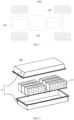
- FIG. 1 is a schematic diagram showing a structure of the vehicle 1000 according to some embodiments of the present disclosure.
- the vehicle 1000 may be a fuel vehicle, a gas vehicle, or a new energy vehicle.
- the new energy vehicle may be a battery electric vehicle, a hybrid electric vehicle, an extended range vehicle, or the like.
- a battery 100 is disposed in the vehicle 1000, and the battery 100 may be disposed at a bottom or a head or a tail of the vehicle 1000.
- the battery 100 can be configured to supply power to the vehicle 1000.
- the battery 100 may be used as an operational power source of the vehicle 1000.
- the vehicle 1000 may further include a controller 200 and a motor 300.
- the controller 200 is configured to control the battery 100 to supply power to the motor 300, e.g., for operational power needs in starting, navigation, and traveling of the vehicle 1000.
- the battery 100 may not only serve as an operational power source of the vehicle 1000, but also serve as a drive power source of the vehicle 1000 in lieu of, or in part in lieu of a fuel oil or a natural gas to provide drive power for the vehicle 1000.
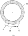
- FIG. 2 is an exploded view of the battery 100 according to some embodiments of the present disclosure.
- the battery 100 includes a case body 10 and a battery cell 20 accommodated in the case body 10.
- the case body 10 provides an accommodation space for the battery cell 20, and may be in various structures.
- the case body 10 may include a first portion 11 and a second portion 12 that cap each other.
- the first portion 11 and the second portion 12 together define the accommodation space for accommodating the battery cell 20.
- the second portion 12 may be in a hollow structure having an opening at one end thereof while the first portion 11 may be in a plate-like structure.
- the first portion 11 caps the second portion 12 at the opening side to enable the first portion 11 and the second portion 12 to define the accommodation space.
- each of the first portion 11 and the second portion 12 may be in the hollow structure having an opening at one end thereof, and the first portion 11 at the opening side caps over the second portion 12 at the opening side.
- the case body 10 formed by the first portion 11 and the second portion 12 may be of various shapes, for example, a cylinder, a cuboid, and so on.
- a plurality of battery cells 20 may be provided.
- the plurality of battery cells 20 may be connected in series or in parallel or in series and parallel.
- the expression "in series and parallel” means that the plurality of battery cells 20 is connected both in series and in parallel.
- the plurality of battery cells 20 may be directly connected in series or in parallel or in series and parallel, and then accommodated in the case body 10 as a whole.
- the plurality of battery cells 20 may be connected in series or in parallel or in series and parallel to form a battery module, and then a plurality of battery modules may be connected in series or in parallel or in series and parallel and accommodated in the case body 10 as a whole.
- the battery 100 may further have other structures.
- the battery 100 may further include a busbar configured to implement an electrical connection between the plurality of battery cells 20.
- Each battery cell 20 may be a rechargeable battery or a primary battery.
- the battery cell 20 may be a lithium-sulfur battery, a sodium-ion battery, or a magnesium-ion battery. The present disclosure is not limited to any of these examples.
- the battery cell 20 may be in a shape of a cylinder, a flat body, a cuboid, or the like.
- FIG. 3 is an exploded view of a structure of the battery cell 20 according to some embodiments of the present disclosure.
- the battery cell 20 is the smallest unit that makes up the battery.
- the battery cell 20 includes an end cover 21, a housing 22, an electrode assembly 23, and other functional members.
- the end cover 21 is a member that covers an opening of the housing 22 to isolate an internal environment of the battery cell 20 from an external environment.
- a shape of the end cover 21 may be adapted to a shape of the housing 22 to cooperate with the housing 22.
- the end cover 21 may be made of a material having a certain degree of hardness and strength (e.g., an aluminum alloy). In this way, the end cover 21 is less likely to deform when subjected to a compression and a collision, enabling the battery cell 20 to have a higher structural strength and improved safety performance.
- Functional members such as an electrode terminal 21a may be disposed on the end cover 21.
- the electrode terminal 21a can be configured to be electrically connected to the electrode assembly 23 to output or input electric energy of the battery cell 20.
- a pressure relief mechanism may further be disposed on the end cover 21.
- the pressure relief mechanism is configured to release an internal pressure of the battery cell 20 when the internal pressure or a temperature of the battery cell 20 reaches a threshold.
- the end cover 21 may be made of a variety of materials, such as copper, iron, aluminum, stainless steel, aluminum alloy, and plastic. The embodiments of the present disclosure are not specifically limited to any of these examples.
- an insulation member may also be disposed on an inner side of the end cover 21. The insulation member can be configured to isolate an electrical connection member in the housing 22 from the end cover 21, to reduce a short-circuit risk.
- the insulation member may be made of plastic, rubber, or the like.
- the housing 22 is an assembly cooperating with the end cover 21 to form the internal environment of the battery cell 20.
- the formed internal environment can accommodate the electrode assembly 23, the electrolyte, and other members.
- the housing 22 and the end cover 21 may be independent members.
- An opening may be formed on the housing 22.
- the internal environment of the battery cell 20 may be formed by covering the opening with the end cover 21.
- the end cover 21 and the housing 22 may also be integrally formed.
- a common connection surface may be formed with the end cover 21 and the housing 22 before other members are put into the housing.
- the housing 22 may be in various shapes and may have various dimensions, such as in a cuboid shape, in a cylinder shape, and in a hexagonal prism shape. In a further embodiment, the shape of the housing 22 may be determined based on a specific shape and dimension size of the electrode assembly 23.
- the housing 22 may be made of various materials, such as copper, iron, aluminum, stainless steel, aluminum alloy, and plastic. The embodiments of the present disclosure are not limited to any of these examples.
- the electrode assembly 23 is a member, in the battery cell 100, where an electrochemical reaction occurs.
- One or more electrode assemblies 23 may be contained in the housing 22.
- the electrode assembly 23 is formed primarily by winding or laminating a positive plate and a negative plate.
- a separator is located between the positive plate and the negative plate.
- Portions of the positive plate and the negative plate that have active substances form a main body portion of a cell assembly.
- Portions of the positive plate and the negative plate that have no active substances each form a tab 23a.
- a positive electrode tab and a negative electrode tab may be both located at one end of the main body portion, or may be located at two ends of the main body portion, respectively.
- the tab 23a is connected to the electrode terminal to form a current circuit.
- the end cover 21 has a mounting surface for being mounted with a seal 40.
- An injection hole 32 is defined on the end cover 21.
- an accommodation groove 33 is recessed from the mounting surface of the end cover 21.
- the injection hole 32 is defined at a bottom of the accommodation groove 33 to enable an end of the injection hole 32 to be in communication with the accommodation groove 33 and another end of the injection hole 32 to penetrate the end cover 21 to an inner surface of the end cover 21.
- an adhesive nail 31 is inserted into the injection hole 32 to seal the injection hole 32.
- the seal 40 is located in the accommodation groove 33.
- the accommodation groove 33 can limit a radial movement of the seal 40.
- the seal 40 is welded to the end cover 21.
- a conventional seal 40 has a substantially truncated cone contour. As illustrated in FIG. 4 , in a cross section parallel to an axial direction of the seal 40, an upper end of the adhesive nail 31 cooperates with a bottom surface of the seal 40. A side wall of the accommodation groove 33 is an oblique surface. An outer annular wall of the seal 40 cooperates with the side wall of the accommodation groove 33. In addition, an end of the outer annular wall of the seal 40 facing away from the adhesive nail 31 is attached to an inner wall of the accommodation groove 33, to fill the accommodation groove 33 with the seal 40. A top surface of the seal 40 is flush with a top surface of the end cover 21. Or the top surface of the seal 40 is slightly higher than the top surface of the end cover 21. A circular junction between the seal 40 and the end cover 21 is welded to weld and fix the seal 40 to the end cover 21.
- a laser welding device is used as the welding assembly.
- the welding assembly When performing welding, the welding assembly emits high-energy laser light to a junction between the seal 40 and the end cover 21. Under an action of the high-energy laser light, a liquid metallic portion having a certain shape is formed at the junction between the seal 40 and the end cover 21.
- the liquid metallic portion is called a welding pool.
- a weld seam is formed when a metallic material at a tail of the pool cools and crystallizes as the welding assembly moves.
- the battery production capacity is limited due to a low welding speed of the pulsed laser.
- the low beat rate of the pulsed laser light due to the low beat rate of the pulsed laser light, a large number of welding devices are needed, which leads to the poor consistency of penetration.
- the battery cell 20 includes: the end cover 21 having the injection hole 32 defined thereon; and the seal 40 sealingly connected to the injection hole 32.
- a first weld segment 50 and a second weld segment 60 are formed between the seal 40 and the end cover 21.
- An annular weld seam surrounding the seal 40 is formed by enclosing with at least a part of the first weld segment 50 and at least a part of the second weld segment 60 together.
- the first weld segment 50 is formed by continuous laser light.
- the second weld segment 60 is formed by pulsed laser light.
- the first weld segment 50 and the second weld segment 60 are formed between the seal 40 and the end cover 21.
- the annular weld seam surrounding the seal 40 is formed by enclosing with at least a part of the first weld segment 50 and at least a part of the second weld segment 60 together.
- the first weld segment 50 is formed by the continuous laser light.
- the second weld segment 60 is formed by the pulsed laser light. Therefore, the high welding rate of the continuous laser light and the high excellent rate of the pulsed laser light can be combined to avoid the problems of the low welding speed and the low excellent rate during the welding for the seal 40, contributing to improving the welding rate and the welding yield rate of the seal 40.
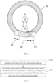
- the second weld segment 60 includes a head 61, a middle 62, and a tail 63 that are sequentially connected.
- the annular weld seam is formed by connecting the middle 62 to the first weld segment 50.
- the second weld segment 60 is divided, based on a sequence of formation time of the second weld segment 60, into the head 61, the middle 62, and the tail 63 that are sequentially connected.
- the welding excellent rate can be improved through forming the annular weld seam by connecting the middle 62 of the second weld segment 60 to the first weld segment 50.
- the head 61 and the tail 63 are equal in length. Therefore, the head 61 and the tail 63 can be arranged symmetrically to embellish the annular weld seam.
- the head 61 and/or the tail 63 partially overlaps the first weld segment 50.
- the first welding angle ⁇ 1 may range from 270° to 340°.
- the second welding angle ⁇ 2 may range from 40° to 90°.
- the first weld segment 50 and the second weld segment 60 need to overlap by 10° or more. Accordingly, a sum of the first welding angle ⁇ 1 and the second welding angle ⁇ 2 is equal to or greater than 370°.
- the sealing performance of the seal 40 can be improved.
- the middle 62 has a dimension equal to or greater than 1 mm.
- the dimension of the middle 62 of the second weld segment 60 By setting the dimension of the middle 62 of the second weld segment 60 to be equal to or greater than 1 mm, a sufficient region can be reserved for discharge of electrolyte vapors during the welding to avoid a formation of a defect in the finishing spot.
- a length of the first weld segment 50 in the annular weld seam is greater than a length of the second weld segment 60 in the annular weld seam.
- continuous laser light welding can be ensured to be a primary welding method, and pulsed laser light welding can be ensured to be a secondary welding method. Since the continuous laser light welding has a higher welding rate, a welding rate for the seal can be increased.
- a spacing between weld joints of the first weld segment 50 is equal to a spacing between weld joints of the second weld segment 60.
- the continuous laser light may be modulated continuous laser light.
- the modulated continuous laser light may be modulated into a pulsed mode to enable the continuous first weld segment 50 to form a dotted-weld joint appearance consistent with an appearance of the second weld segment 60 subsequently formed by the pulsed laser light.
- the pulsed laser light may be YAG pulsed laser light, which ensures a smooth and beautiful weld seam in the finishing spot.
- a diameter of each of weld joints of the first weld segment 50 is equal to a diameter of each of weld joints of the second weld segment 60.
- FIG. 8 is a flowchart illustrating a welding method according to some embodiments of the present disclosure.
- the welding method is used for welding the seal 40 to a material.
- the method includes operations at blocks.
- the continuous laser is controlled, in response to welding the seal 40, to emit the continuous laser light to form the first weld segment 50 of the seal 40.
- the pulsed laser in response to controlling the continuous laser to emit the continuous laser light to form the first weld segment 50 of the seal 40, the pulsed laser is controlled simultaneously to emit the pulsed laser light to form the second weld segment 60 of an immediately previous seal 40.
- the pulsed laser can be simultaneously controlled, in response to controlling the continuous laser to emit the continuous laser light to form the first weld segment 50 of the seal 40, to emit the pulsed laser light to form the second weld segment 60 of the immediately previous seal 40, a welding speed can be increased.
- a welding duration for the continuous laser to weld the first weld segment of the seal is equal to a welding duration for the pulsed laser to weld the second weld segment of the immediately previous seal.
- t 1 represents a sum of an acceleration duration of the continuous laser and a deceleration duration of the continuous laser.
- the acceleration duration is time taken to accelerate the welding speed of the continuous laser from zero to a stable welding speed corresponding to the continuous laser.
- the deceleration duration is time taken to decelerate the welding speed of the continuous laser from the stable welding speed corresponding to the continuous laser to zero.
- the stable welding speed is a speed at which the laser emits laser light to start welding stably.
- the continuous laser corresponds to the stable welding speed of 80 mm/s.
- ⁇ 1 represents the first welding angle corresponding to the first weld segment 50.
- R represents a radius of a welding trajectory of the seal 40.
- v 1 represents the welding speed of the continuous laser.
- t 2 represents a sum of an acceleration duration and a deceleration duration of the pulsed laser.
- the acceleration duration is time taken to accelerate the welding speed of the pulsed laser from zero to a stable welding speed corresponding to the pulsed laser.
- the deceleration duration is time taken to decelerate the welding speed of the continuous laser from the stable welding speed corresponding to the pulsed laser to zero.
- the pulsed laser corresponds to the stable welding speed of 7 mm/s.
- ⁇ 2 represents the second welding angle corresponding to the second weld segment 60.
- v 2 represents the welding speed of the pulsed laser. ⁇ 1 + ⁇ 2 > 2 ⁇ .
- the pulsed laser is controlled to emit the pulsed laser light to form the second weld segment 60 of the seal 40 subsequent to a completion of welding by the continuous laser.
- the annular weld seam surrounding the seal 40 is formed by enclosing with at least a part of the first weld segment 50 and at least a part of the second weld segment 60 together.
- the continuous laser is controlled to emit the continuous laser light to form the first weld segment 50 of the seal 40.
- the pulsed laser is controlled to emit the pulsed laser light to form the second weld segment 60 of the seal 40 subsequent to the completion of the welding by the continuous laser.
- the annular weld seam surrounding the seal 40 is formed by enclosing with at least a part of the first weld segment 50 and at least a part of the second weld segment 60 together.
- the seal 40 is welded in segments.
- the annular weld seam of the seal 40 is formed by enclosing with the first weld segment 50 and the second weld segment 60 together.
- the first weld segment 50 is formed by the continuous laser light emitted by the continuous laser.
- the second weld segment 60 is formed by the pulsed laser light emitted by the pulsed laser. Therefore, the high welding rate of the continuous laser light and the high excellent rate of the pulsed laser light can be combined to avoid the problems of the low welding speed and the low excellent rate during the welding for the seal 40, contributing to improving the welding rate and the welding yield rate of the seal 40.
- a length of an unwelded region between the seal 40 and the material is greater than or equal to 1 mm, subsequent to the completion of the welding by the continuous laser and prior to welding by the pulsed laser.
- the length of the unwelded region between the seal 40 and the material can be greater than or equal to 1 mm, the sufficient region can be reserved for the electrolyte vapors to be discharged, avoiding the formation of the defect in the finishing spot.
- the pulsed laser is controlled to emit the pulsed laser light to form the second welded segment 60 of the seal 40.
- a sufficient duration can be reserved for the electrolyte vapors to be discharged, which avoids the formation of the defect in the finishing spot.
- the time interval may be pre-set.
- the continuous laser light is modulated continuous laser light
- the pulsed laser light is YAG pulsed laser light
- the continuous laser light As the modulated continuous laser light, an electrolyte contamination tolerance can be increased due to a large spot formed by the modulated continuous laser light. Also, a spot-like appearance formed by the modulated continuous laser light has no difference from an appearance of a weld seam of the subsequent YAG pulsed laser light, which can ensure the uniform appearance of the annular weld seam. In addition, during high-speed welding of the modulated continuous laser light, a pore in the finishing spot is reserved to facilitate the discharge of the electrolyte vapors, avoiding the formation of the defect in the finishing spot. By setting the pulsed laser light as the YAG pulsed laser light, a smooth and beautiful weld seam in the finishing spot can be ensured.
- a ratio of a welding speed of the continuous laser to a welding frequency of the continuous laser is equal to a ratio of a welding speed of the pulsed laser to a welding frequency of the pulsed laser.
- single point energy emitted by the continuous laser is equal to single point energy emitted by the pulsed laser.
- FIG. 9 is a schematic diagram of a welding device for a welding method according to some embodiments of the present disclosure.
- the welding device includes: a carrier table 70 configured to hold a seal 40 and a material; and a welding platform 80 disposed in correspondence to the carrier table 70.
- a continuous laser 86 and a pulsed laser 87 are disposed on the welding platform 80.
- the continuous laser 86 is configured to form the first weld segment 50 between the seal 40 and the material.
- the pulsed laser 87 is configured to form the second weld segment 60 between the seal 40 and the material.
- the annular weld seam surrounding the seal 40 is formed by enclosing with at least a part of the first weld segment 50 and at least a part of the second weld segment 60 together.
- the welding platform 80 being disposed in correspondence to the carrier table 70 may mean that a position where the seal 40 and the material are placed on the carrier table 70 corresponds to a station of the welding platform 80.
- an unloading assembly 81, a loading assembly 82, a laser cleaning assembly 83, a nailing assembly 84, a pre-welding assembly 85, and a CCD inspection assembly 88 may be disposed on the welding platform 80.
- the continuous laser 86 starts to weld the first weld segment 50 of the seal 40 of an N-th cell subsequent to loading/laser cleaning/nailing performed on the cell, and at this time the pulsed laser 87 at a next station simultaneously welds the second weld segment 60 of the seal 40 of an (N-1)-th cell.
- t 1 represents the sum of the acceleration duration of the continuous laser and the deceleration duration of the continuous laser.
- the acceleration duration is the time taken to accelerate the welding speed of the continuous laser from zero to the stable welding speed corresponding to the continuous laser.
- the deceleration duration is the time taken to decelerate the welding speed of the continuous laser from the stable welding speed corresponding to the continuous laser to zero.
- the stable welding speed is the speed at which the laser emits the laser light to start welding stably.
- the continuous laser corresponds to the stable welding speed of 80 mm/s.
- ⁇ 1 represents the first welding angle corresponding to the first weld segment 50.
- R represents the radius of the welding trajectory of the seal 40.
- v 1 represents the welding speed of the continuous laser.
- t 2 represents the sum of the acceleration duration and the deceleration duration of the pulsed laser.
- the acceleration duration is time taken to accelerate the welding speed of the pulsed laser from zero to the stable welding speed corresponding to the pulsed laser.
- the deceleration duration is the time taken to decelerate the welding speed of the continuous laser from the stable welding speed corresponding to the pulsed laser to zero.
- the pulsed laser corresponds to the stable welding speed of 7 mm/s.
- ⁇ 2 represents the second welding angle corresponding to the second weld segment 60.
- v 2 represents the welding speed of the pulsed laser. ⁇ 1 + ⁇ 2 > 2 ⁇ .
- the continuous laser 86 and the pulsed laser 87 are disposed on the welding platform 80.
- the continuous laser 86 is configured to form the first weld segment 50 between the seal 40 and the material.
- the pulsed laser 87 is configured to form the second weld segment 60 between the seal 40 and the material.
- the annular weld seam of the seal 40 is formed by enclosing with at least a part of the first weld segment 50 and at least a part of the second weld segment 60 together. Therefore, the high welding rate of the continuous laser light and the high excellent rate of the pulsed laser light can be combined to avoid the problems of the low welding speed and the low excellent rate during the welding for the seal 40, contributing to improving the welding rate and the welding yield rate of the seal 40.
- the carrier table 70 is rotatable and is configured to switch between the continuous laser 86 and the pulsed laser 87 for the seal 40 and the material.
- the carrier table 70 is rotated subsequent to a completion of welding, by the continuous laser 86, the first weld segment 50 of the seal 40 of the N-th cell, to align the seal 40 of the N-th cell with the station of the pulsed laser 87.
- the pulsed laser 87 proceeds to weld the second weld segment 60 of the seal 40 of the N-th cell.
Landscapes
- Chemical & Material Sciences (AREA)
- Chemical Kinetics & Catalysis (AREA)
- Electrochemistry (AREA)
- General Chemical & Material Sciences (AREA)
- Physics & Mathematics (AREA)
- Optics & Photonics (AREA)
- Engineering & Computer Science (AREA)
- Plasma & Fusion (AREA)
- Mechanical Engineering (AREA)
- Inorganic Chemistry (AREA)
- Sealing Battery Cases Or Jackets (AREA)
Applications Claiming Priority (1)
| Application Number | Priority Date | Filing Date | Title |
|---|---|---|---|
| PCT/CN2022/127138 WO2024086992A1 (zh) | 2022-10-24 | 2022-10-24 | 电池单体、电池、用电装置、焊接方法以及设备 |
Publications (2)
| Publication Number | Publication Date |
|---|---|
| EP4572002A1 true EP4572002A1 (de) | 2025-06-18 |
| EP4572002A4 EP4572002A4 (de) | 2025-08-20 |
Family
ID=90829696
Family Applications (1)
| Application Number | Title | Priority Date | Filing Date |
|---|---|---|---|
| EP22962980.3A Pending EP4572002A4 (de) | 2022-10-24 | 2022-10-24 | Batteriezelle, batterie, elektrische vorrichtung, schweissverfahren und vorrichtung |
Country Status (4)
| Country | Link |
|---|---|
| US (1) | US20250070437A1 (de) |
| EP (1) | EP4572002A4 (de) |
| CN (1) | CN118541870A (de) |
| WO (1) | WO2024086992A1 (de) |
Families Citing this family (2)
| Publication number | Priority date | Publication date | Assignee | Title |
|---|---|---|---|---|
| ES2561133B1 (es) | 2014-07-24 | 2016-12-01 | Alejandro Rodriguez Barros | Retrovisor exterior multifunción con dispositivo emisor laser incorporado |
| CN119794562A (zh) * | 2025-01-06 | 2025-04-11 | 合肥国轩高科动力能源有限公司 | 一种负极极耳盖板激光焊接方法 |
Family Cites Families (7)
| Publication number | Priority date | Publication date | Assignee | Title |
|---|---|---|---|---|
| JP4929606B2 (ja) * | 2005-03-16 | 2012-05-09 | トヨタ自動車株式会社 | 密閉型蓄電装置及びその製造方法 |
| JP6045783B2 (ja) * | 2011-01-25 | 2016-12-14 | 株式会社東芝 | 二次電池及び二次電池の製造方法 |
| JP6091084B2 (ja) * | 2012-05-18 | 2017-03-08 | 株式会社アマダミヤチ | レーザ加工方法及びレーザ加工装置 |
| CN107335914B (zh) * | 2017-05-19 | 2019-05-10 | 大族激光科技产业集团股份有限公司 | 动力电池及其密封钉的焊接方法 |
| CN114074220A (zh) * | 2020-08-20 | 2022-02-22 | 大族激光科技产业集团股份有限公司 | 一种动力电池及其密封钉的激光焊接方法 |
| CN217214996U (zh) * | 2021-11-29 | 2022-08-16 | 常州微宙电子科技有限公司 | 锂离子电池防爆结构和包含该结构的锂离子电池 |
| CN217306721U (zh) * | 2022-06-24 | 2022-08-26 | 宁德时代新能源科技股份有限公司 | 端盖组件、电池单体、电池、用电装置及焊接设备 |
-
2022
- 2022-10-24 WO PCT/CN2022/127138 patent/WO2024086992A1/zh not_active Ceased
- 2022-10-24 EP EP22962980.3A patent/EP4572002A4/de active Pending
- 2022-10-24 CN CN202280088334.1A patent/CN118541870A/zh active Pending
-
2024
- 2024-11-14 US US18/946,955 patent/US20250070437A1/en active Pending
Also Published As
| Publication number | Publication date |
|---|---|
| WO2024086992A1 (zh) | 2024-05-02 |
| CN118541870A (zh) | 2024-08-23 |
| US20250070437A1 (en) | 2025-02-27 |
| EP4572002A4 (de) | 2025-08-20 |
Similar Documents
| Publication | Publication Date | Title |
|---|---|---|
| US20250070437A1 (en) | Battery cell, battery, electric apparatus, and welding method and device | |
| US20240154218A1 (en) | Battery cell, battery, and electrical apparatus | |
| EP4395050A1 (de) | Batteriezelle, batterie und elektrische vorrichtung | |
| EP4418411A1 (de) | Wärmeschutzkomponente, batterie und elektrische vorrichtung | |
| US20240250397A1 (en) | Battery cover plate assembly, battery cell, battery, and power consuming device | |
| US20250246775A1 (en) | Battery cell and assembling method thereof, battery, electrical apparatus, and assembling assembly | |
| US20240047836A1 (en) | Battery cell, battery, electrical device, and device and method for manufacturing battery cell | |
| CN116686156A (zh) | 电池的顶盖组件、电池和用电装置 | |
| EP4379949A1 (de) | Batteriezelle, batterie, elektrische vorrichtung, verfahren zur herstellung einer batteriezelle und vorrichtung | |
| US20240145889A1 (en) | Insulation patch, battery cell, battery, and device | |
| US20250337064A1 (en) | Battery cell, battery, and electrical apparatus | |
| US20250260112A1 (en) | Plate assembly, box body, battery, and electric apparatus | |
| US20250105454A1 (en) | Battery cell, battery, and electrical device | |
| US20240006703A1 (en) | Battery, power consuming device and method for manufacturing battery | |
| US20230207983A1 (en) | Battery cell, battery, electric apparatus, and manufacturing method and device of battery cell | |
| KR102932827B1 (ko) | 배터리 셀, 배터리, 전기 장치 및 배터리 셀의 제조 방법 | |
| CN119820093A (zh) | 一种焊接压板、焊接系统和焊接方法 | |
| CN118056320A (zh) | 焊接方法、电池单体、电池和用电设备 | |
| US12476333B2 (en) | Battery cell having conductive piece close to welding region | |
| US20250087811A1 (en) | Support assembly, battery box, battery, and electric device | |
| CN223390723U (zh) | 电池装置、用电设备及储能设备 | |
| CN222720637U (zh) | 电池单体、密封件、电池装置及用电装置 | |
| US20250286258A1 (en) | Battery cell, battery, and electric apparatus | |
| US20250286181A1 (en) | Battery cell, manufacturing method of housing assembly, battery, and electric apparatus | |
| CN118922992A (zh) | 泄压装置、电池单体、电池、用电设备及制造方法 |
Legal Events
| Date | Code | Title | Description |
|---|---|---|---|
| STAA | Information on the status of an ep patent application or granted ep patent |
Free format text: STATUS: THE INTERNATIONAL PUBLICATION HAS BEEN MADE |
|
| PUAI | Public reference made under article 153(3) epc to a published international application that has entered the european phase |
Free format text: ORIGINAL CODE: 0009012 |
|
| STAA | Information on the status of an ep patent application or granted ep patent |
Free format text: STATUS: REQUEST FOR EXAMINATION WAS MADE |
|
| 17P | Request for examination filed |
Effective date: 20250311 |
|
| AK | Designated contracting states |
Kind code of ref document: A1 Designated state(s): AL AT BE BG CH CY CZ DE DK EE ES FI FR GB GR HR HU IE IS IT LI LT LU LV MC ME MK MT NL NO PL PT RO RS SE SI SK SM TR |
|
| A4 | Supplementary search report drawn up and despatched |
Effective date: 20250721 |
|
| RIC1 | Information provided on ipc code assigned before grant |
Ipc: H01M 50/636 20210101AFI20250715BHEP Ipc: H01M 50/645 20210101ALI20250715BHEP Ipc: B23K 26/21 20140101ALI20250715BHEP Ipc: B23K 26/20 20140101ALI20250715BHEP Ipc: H01M 50/15 20210101ALI20250715BHEP Ipc: H01M 50/169 20210101ALI20250715BHEP Ipc: H01M 50/184 20210101ALI20250715BHEP Ipc: H01M 50/186 20210101ALI20250715BHEP Ipc: H01M 50/191 20210101ALI20250715BHEP Ipc: H01M 50/183 20210101ALI20250715BHEP |
|
| DAV | Request for validation of the european patent (deleted) | ||
| DAX | Request for extension of the european patent (deleted) |