EP4572001A1 - Sekundärbatterie - Google Patents
Sekundärbatterie Download PDFInfo
- Publication number
- EP4572001A1 EP4572001A1 EP23817283.7A EP23817283A EP4572001A1 EP 4572001 A1 EP4572001 A1 EP 4572001A1 EP 23817283 A EP23817283 A EP 23817283A EP 4572001 A1 EP4572001 A1 EP 4572001A1
- Authority
- EP
- European Patent Office
- Prior art keywords
- injection hole
- liquid injection
- secondary battery
- cap plate
- plate
- Prior art date
- Legal status (The legal status is an assumption and is not a legal conclusion. Google has not performed a legal analysis and makes no representation as to the accuracy of the status listed.)
- Pending
Links
Images


Classifications
-
- H—ELECTRICITY
- H01—ELECTRIC ELEMENTS
- H01M—PROCESSES OR MEANS, e.g. BATTERIES, FOR THE DIRECT CONVERSION OF CHEMICAL ENERGY INTO ELECTRICAL ENERGY
- H01M50/00—Constructional details or processes of manufacture of the non-active parts of electrochemical cells other than fuel cells, e.g. hybrid cells
- H01M50/60—Arrangements or processes for filling or topping-up with liquids; Arrangements or processes for draining liquids from casings
- H01M50/609—Arrangements or processes for filling with liquid, e.g. electrolytes
- H01M50/627—Filling ports
-
- H—ELECTRICITY
- H01—ELECTRIC ELEMENTS
- H01M—PROCESSES OR MEANS, e.g. BATTERIES, FOR THE DIRECT CONVERSION OF CHEMICAL ENERGY INTO ELECTRICAL ENERGY
- H01M50/00—Constructional details or processes of manufacture of the non-active parts of electrochemical cells other than fuel cells, e.g. hybrid cells
- H01M50/10—Primary casings; Jackets or wrappings
- H01M50/102—Primary casings; Jackets or wrappings characterised by their shape or physical structure
- H01M50/103—Primary casings; Jackets or wrappings characterised by their shape or physical structure prismatic or rectangular
-
- H—ELECTRICITY
- H01—ELECTRIC ELEMENTS
- H01M—PROCESSES OR MEANS, e.g. BATTERIES, FOR THE DIRECT CONVERSION OF CHEMICAL ENERGY INTO ELECTRICAL ENERGY
- H01M50/00—Constructional details or processes of manufacture of the non-active parts of electrochemical cells other than fuel cells, e.g. hybrid cells
- H01M50/10—Primary casings; Jackets or wrappings
- H01M50/147—Lids or covers
- H01M50/148—Lids or covers characterised by their shape
- H01M50/15—Lids or covers characterised by their shape for prismatic or rectangular cells
-
- H—ELECTRICITY
- H01—ELECTRIC ELEMENTS
- H01M—PROCESSES OR MEANS, e.g. BATTERIES, FOR THE DIRECT CONVERSION OF CHEMICAL ENERGY INTO ELECTRICAL ENERGY
- H01M50/00—Constructional details or processes of manufacture of the non-active parts of electrochemical cells other than fuel cells, e.g. hybrid cells
- H01M50/30—Arrangements for facilitating escape of gases
-
- H—ELECTRICITY
- H01—ELECTRIC ELEMENTS
- H01M—PROCESSES OR MEANS, e.g. BATTERIES, FOR THE DIRECT CONVERSION OF CHEMICAL ENERGY INTO ELECTRICAL ENERGY
- H01M50/00—Constructional details or processes of manufacture of the non-active parts of electrochemical cells other than fuel cells, e.g. hybrid cells
- H01M50/40—Separators; Membranes; Diaphragms; Spacing elements inside cells
-
- H—ELECTRICITY
- H01—ELECTRIC ELEMENTS
- H01M—PROCESSES OR MEANS, e.g. BATTERIES, FOR THE DIRECT CONVERSION OF CHEMICAL ENERGY INTO ELECTRICAL ENERGY
- H01M50/00—Constructional details or processes of manufacture of the non-active parts of electrochemical cells other than fuel cells, e.g. hybrid cells
- H01M50/50—Current conducting connections for cells or batteries
- H01M50/543—Terminals
- H01M50/547—Terminals characterised by the disposition of the terminals on the cells
- H01M50/548—Terminals characterised by the disposition of the terminals on the cells on opposite sides of the cell
-
- H—ELECTRICITY
- H01—ELECTRIC ELEMENTS
- H01M—PROCESSES OR MEANS, e.g. BATTERIES, FOR THE DIRECT CONVERSION OF CHEMICAL ENERGY INTO ELECTRICAL ENERGY
- H01M50/00—Constructional details or processes of manufacture of the non-active parts of electrochemical cells other than fuel cells, e.g. hybrid cells
- H01M50/50—Current conducting connections for cells or batteries
- H01M50/543—Terminals
- H01M50/552—Terminals characterised by their shape
- H01M50/553—Terminals adapted for prismatic, pouch or rectangular cells
-
- H—ELECTRICITY
- H01—ELECTRIC ELEMENTS
- H01M—PROCESSES OR MEANS, e.g. BATTERIES, FOR THE DIRECT CONVERSION OF CHEMICAL ENERGY INTO ELECTRICAL ENERGY
- H01M50/00—Constructional details or processes of manufacture of the non-active parts of electrochemical cells other than fuel cells, e.g. hybrid cells
- H01M50/50—Current conducting connections for cells or batteries
- H01M50/572—Means for preventing undesired use or discharge
- H01M50/584—Means for preventing undesired use or discharge for preventing incorrect connections inside or outside the batteries
- H01M50/586—Means for preventing undesired use or discharge for preventing incorrect connections inside or outside the batteries inside the batteries, e.g. incorrect connections of electrodes
-
- H—ELECTRICITY
- H01—ELECTRIC ELEMENTS
- H01M—PROCESSES OR MEANS, e.g. BATTERIES, FOR THE DIRECT CONVERSION OF CHEMICAL ENERGY INTO ELECTRICAL ENERGY
- H01M50/00—Constructional details or processes of manufacture of the non-active parts of electrochemical cells other than fuel cells, e.g. hybrid cells
- H01M50/50—Current conducting connections for cells or batteries
- H01M50/572—Means for preventing undesired use or discharge
- H01M50/584—Means for preventing undesired use or discharge for preventing incorrect connections inside or outside the batteries
- H01M50/59—Means for preventing undesired use or discharge for preventing incorrect connections inside or outside the batteries characterised by the protection means
- H01M50/593—Spacers; Insulating plates
-
- H—ELECTRICITY
- H01—ELECTRIC ELEMENTS
- H01M—PROCESSES OR MEANS, e.g. BATTERIES, FOR THE DIRECT CONVERSION OF CHEMICAL ENERGY INTO ELECTRICAL ENERGY
- H01M50/00—Constructional details or processes of manufacture of the non-active parts of electrochemical cells other than fuel cells, e.g. hybrid cells
- H01M50/60—Arrangements or processes for filling or topping-up with liquids; Arrangements or processes for draining liquids from casings
- H01M50/609—Arrangements or processes for filling with liquid, e.g. electrolytes
- H01M50/618—Pressure control
-
- Y—GENERAL TAGGING OF NEW TECHNOLOGICAL DEVELOPMENTS; GENERAL TAGGING OF CROSS-SECTIONAL TECHNOLOGIES SPANNING OVER SEVERAL SECTIONS OF THE IPC; TECHNICAL SUBJECTS COVERED BY FORMER USPC CROSS-REFERENCE ART COLLECTIONS [XRACs] AND DIGESTS
- Y02—TECHNOLOGIES OR APPLICATIONS FOR MITIGATION OR ADAPTATION AGAINST CLIMATE CHANGE
- Y02E—REDUCTION OF GREENHOUSE GAS [GHG] EMISSIONS, RELATED TO ENERGY GENERATION, TRANSMISSION OR DISTRIBUTION
- Y02E60/00—Enabling technologies; Technologies with a potential or indirect contribution to GHG emissions mitigation
- Y02E60/10—Energy storage using batteries
Definitions
- An embodiment of the present invention relates to a secondary battery.
- secondary batteries are batteries that are chargeable and dischargeable.
- the batteries are used in small portable electronic devices such as mobile phones and camcorders, and in the case of high-capacity batteries, the batteries are widely used as power sources for driving motors in hybrid and electric vehicles.
- the secondary batteries may be classified into cylindrical, prismatic, and pouch-type (or polymer-type) secondary batteries, etc., according to their external appearance.
- the prismatic battery may have a structure in which an electrode assembly with a separator interposed between a positive electrode plate and a negative electrode plate, an electrolyte, and the like are embedded in a can, and a cap plate is coupled to an open top surface of the can.
- An embodiment of the present invention provides a secondary battery capable of improving liquid injectability.
- a secondary battery includes: an electrode assembly comprising a first electrode plate, a second electrode plate, and a separator interposed between the first electrode plate and the second electrode plate; a can having ends that are opened to left and right sides and provided with a space therein to accommodate the electrode assembly; a first cap plate configured to seal the left end of the can; a second cap plate configured to seal the right end of the can; a first terminal installed on the first cap plate so as to be electrically connected to the first electrode plate; a second terminal installed on the second cap plate so as to be electrically connected to the second electrode plate; a first liquid injection hole defined in the first cap plate; and a second liquid injection hole defined in the second cap plate.
- the first liquid injection hole may be disposed above the first terminal in the first cap plate.
- the second liquid injection hole may be disposed above the second terminal in the second cap plate.
- the second liquid injection hole may be disposed at the same height as the first liquid injection hole.
- the second liquid injection hole may be disposed above the first liquid injection hole.
- first liquid injection hole and the second liquid injection hole may be disposed at heights different from each other.
- the second liquid injection hole may have the same size as the first liquid injection hole.
- the second liquid injection hole may have a size less than that of the first liquid injection hole.
- first liquid injection hole and the second liquid injection hole may have sizes different from each other.
- first liquid injection hole may be configured to inject an electrolyte into the can
- second liquid injection hole is configured to suction air from the inside of the can.
- an insulating member may be formed in at least one of between the electrode assembly and the first cap plate or between the electrode assembly and the second cap plate.
- an insulating member may be formed in at least one of between the first cap plate and the first terminal or between the second cap plate and the second terminal.
- the embodiment of the present invention may provide the secondary battery in which the electrolyte is injected into the can through the first liquid injection hole to discharge the electrolyte or suction the air, thereby improving the liquid injectability.
- Embodiments of the present invention may, however, be embodied in many different forms and should not be construed as being limited to the embodiments set forth herein; rather, these embodiments are provided so that those skilled in the art thoroughly understand the present invention. Rather, these embodiments are provided so that this disclosure will be thorough and complete, and will fully convey the scope of the present invention to those skilled in the art.
- first As used herein, terms such as "first,” “second,” etc. are used to describe various members, components, areas, layers, and/or portions. However, it is obvious that the members, components, areas, layers, and/or portions should not be defined by these terms. The terms do not mean a particular order, up and down, or superiority, and are used only for distinguishing one member, component, area, layer, or portion from another member, component, area, layer, or portion. Thus, a first member, component, area, layer, or portion which will be described may also refer to a second member, component, area, layer, or portion, without departing from the teaching of the present invention.
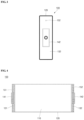
- FIG 1 is a perspective view of a secondary battery 100 according to an embodiment of the present invention
- FIG 2 is a left view of the secondary battery 100 according to an embodiment of the present invention
- FIG 3 is a right view of the secondary battery 100 according to an embodiment of the present invention
- FIG 4 is a cross-sectional view of the secondary battery 100 according to an embodiment of the present invention.
- the secondary battery 100 includes an electrode assembly 110, a can 120, a first cap plate 131, a second cap plate 132, a first terminal 141, a second terminal 142, a first liquid injection hole 151, and a second liquid injection hole 152.
- the electrode assembly 110 includes a first electrode plate, a second electrode plate, and a separator.
- the first electrode plate may be any one of a negative electrode plate and a positive electrode plate.
- the first electrode plate when the first electrode plate is a negative electrode plate, the first electrode plate may include a negative electrode coating portion coated with a negative electrode active material on a conductive metal thin plate, for example, a negative electrode collector made of copper or nickel foil or mesh and a negative electrode non-coating portion that is not coated with the negative electrode active material.
- the negative electrode active material may include a carbon-based material, Si, Sn, tin oxide, a tin alloy composite, transition metal oxide, lithium metal nitrite, or metal oxide.
- the second electrode plate may be the other one of the negative electrode plate and the positive electrode plate.
- the second electrode plate when the second electrode plate is a positive electrode plate, the second electrode plate may include a positive electrode coating portion coated with a positive electrode active material on a conductive metal thin plate, for example, a positive electrode collector made of aluminum foil or mesh and a positive electrode non-coating portion that is not coated with the positive electrode active material.
- the positive electrode active material may be made of a chalcogenide compound, for example, composite metal oxide such as LiCoO2, LiMn2O4, LiNiO2, LiNiMnO2, and the like.
- the separator is disposed between the first electrode plate and the second electrode plate to prevent electrical short-circuit from occurring between the first electrode plate and the second electrode plate.
- the separator may be made of polyethylene, polypropylene, a porous copolymer of polyethylene and polypropylene, or the like.
- the can 120 serves to accommodate the electrode assembly and the electrolyte.
- the can 120 has opened left and right ends and a space therein, based on the drawing.
- the can 120 may be formed in the form of a pipe extending to left and right sides, preferably in a rectangular pipe shape.
- the can 120 may have a safety vent (not shown) on either side and preferably have a safety vent at a narrow side in the rectangular pipe shape.
- the first cap plate 131 is formed in a rectangular plate shape to correspond to one opened end (left end in the drawing) of the can 120. Thus, the first cap plate 131 is welded to one end of the can 120 to seal the one end.
- the second cap plate 132 is formed in a rectangular plate shape to correspond to the other opened end (right end in the drawing) of the can 120. Thus, the second cap plate 132 is welded to the other end of the can 120 to seal the other end.
- the first terminal 141 is electrically connected to the first electrode plate of the electrode assembly and is formed on the first cap plate 131. Thus, the first terminal 141 serves as a terminal on the first cap plate 131.
- the second terminal 142 is electrically connected to the second electrode plate of the electrode assembly and is formed on the second cap plate 132.
- the second terminal 142 serves as a terminal on the second cap plate 132.
- an insulating member (not shown) may be installed in at least one of between the can 120 and the first cap plate 131 or between the can 120 and the second cap plate 123 and/or at least one of between the first cap plate 131 and the first terminal 141 or between the second cap plate 132 and the second terminal 142.
- the insulating member may be installed in at least one of between the electrode assembly 110 and the first cap plate 131 or between the electrode assembly 110 and the second cap plate 132.
- the first liquid injection hole 151 is used to inject the electrolyte into the can 120, and a method for injecting the electrolyte into the can 120 using the same will be described later.
- the first liquid injection hole 151 is formed in the first cap plate 131. More specifically, the first liquid injection hole 151 may be disposed above the first terminal 141 in the first cap plate 131, based on the drawing.
- the second liquid injection hole 152 is also used to inject the electrolyte into the can 120, and a method for injecting the electrolyte into the can 120 using the same will be described later.
- the second liquid injection hole 152 is formed in the second cap plate 132. More specifically, the second liquid injection hole 152 may be disposed above the second terminal 142 in the second cap plate 132, based on the drawing.
- the second liquid injection hole 152 may be disposed at least equal to or higher than the first liquid injection hole 151, based on the drawing.
- the second liquid injection hole 152 may be formed at least equal to or smaller than the first liquid injection hole 151.
- FIG 5 is a view illustrating one method for injecting an electrolyte into a secondary battery according to an embodiment of the present invention.
- an electrolyte injection device is connected to a first liquid injection hole 151, and an electrolyte discharge device is connected to a second liquid injection hole 152.
- an electrolyte is injected into a can 120 through the first liquid injection hole 151 using the electrolyte injection device, the electrolyte is discharged from the inside of the can 120 through the second liquid injection hole 152 using the electrolyte discharge device.
- a flow rate of the electrolyte injected into the can 120 through the first liquid injection hole 151 is controlled to be greater than that of the electrolyte discharged from the inside of the can 120 through the second liquid injection hole 152.
- a difference in flow rate may be differently controlled according to a length, volume, injection amount, desired process time, etc. of the can 120, specific details thereof will be omitted.
- the electrolyte discharged from the inside of the can 120 through the second liquid injection hole 152 may be circulated to the electrolyte injection device and then be injected into the can 120 again through the first liquid injection hole 151.
- liquid injectability in the secondary battery having a terminal part at a side surface thereof, liquid injectability may be improved compared to a case in which the electrolyte is injected into the can through one liquid injection hole, and in particular, the liquid injectability may be more improved in a so-called long cell that is elongated to left and right sides when based on the drawing.
- the second liquid injection hole 152 is disposed above the first liquid injection hole 151, a problem, in which the electrolyte is discharged from the inside of the can 120 through the second liquid injection hole 152 before the electrolyte injected into the can 120 through the first liquid injection hole 151 reaches a target liquid injection amount, may be prevented from occurring.
- the flow rate of the electrolyte injected into the can 120 through the first liquid injection hole 151 may be controlled to be greater than that of the electrolyte discharged from the inside of the can 120 through the second liquid injection hole.
- FIG 6 is a view illustrating another method for injecting an electrolyte into a secondary battery according to an embodiment of the present invention.
- an electrolyte injection device is connected to a first liquid injection hole 151, and a vacuum forming device is connected to a second liquid injection hole 152.
- a vacuum forming device is connected to a second liquid injection hole 152.
- a flow rate of the electrolyte injected into the can 120 through the first liquid injection hole 151 and a pressure of the air suctioned from the inside of the can 120 through the second liquid injection hole 152 are controlled according to preset values.
- the flow rate is differently controlled according to a length, volume, injection amount, desired process time, etc., of the can 120, specific details thereof will be omitted.
- liquid injectability in the secondary battery having a terminal part at a side surface thereof, liquid injectability may be improved compared to a case in which the electrolyte is injected into the can through one liquid injection hole, and in particular, the liquid injectability may be more improved in a so-called long cell that is elongated to left and right sides when based on the drawing.
- the second liquid injection hole 152 is disposed above the first liquid injection hole 151, a problem, in which the electrolyte injected into the can 120 through the first liquid injection hole 151 is introduced into the vacuum forming device may be prevented from occurring.
- the negative electrode terminal and the positive electrode terminal are provided at the upper portion, there is a limitation in utilizing a space above the upper portion.
- the above-described secondary battery is provided with the negative electrode terminal and the positive electrode terminal on the left and right surfaces, the space above the upper portion may be efficiently used.
Landscapes
- Chemical & Material Sciences (AREA)
- Chemical Kinetics & Catalysis (AREA)
- Electrochemistry (AREA)
- General Chemical & Material Sciences (AREA)
- Filling, Topping-Up Batteries (AREA)
Applications Claiming Priority (2)
| Application Number | Priority Date | Filing Date | Title |
|---|---|---|---|
| KR1020220098476A KR20240020455A (ko) | 2022-08-08 | 2022-08-08 | 이차전지 |
| PCT/KR2023/001382 WO2024034757A1 (ko) | 2022-08-08 | 2023-01-31 | 이차전지 |
Publications (1)
| Publication Number | Publication Date |
|---|---|
| EP4572001A1 true EP4572001A1 (de) | 2025-06-18 |
Family
ID=89851768
Family Applications (1)
| Application Number | Title | Priority Date | Filing Date |
|---|---|---|---|
| EP23817283.7A Pending EP4572001A1 (de) | 2022-08-08 | 2023-01-31 | Sekundärbatterie |
Country Status (5)
| Country | Link |
|---|---|
| US (1) | US20250337142A1 (de) |
| EP (1) | EP4572001A1 (de) |
| KR (1) | KR20240020455A (de) |
| CN (1) | CN118104064A (de) |
| WO (1) | WO2024034757A1 (de) |
Family Cites Families (5)
| Publication number | Priority date | Publication date | Assignee | Title |
|---|---|---|---|---|
| KR100696778B1 (ko) * | 2005-04-08 | 2007-03-19 | 삼성에스디아이 주식회사 | 리튬 이온 이차 전지 |
| KR20140060999A (ko) * | 2012-11-13 | 2014-05-21 | 주식회사 엘지화학 | 다수의 전해액 주액구를 포함하는 이차전지 |
| KR102572693B1 (ko) * | 2015-10-02 | 2023-08-31 | 삼성에스디아이 주식회사 | 이차 전지 |
| KR102435380B1 (ko) * | 2015-12-04 | 2022-08-23 | 삼성에스디아이 주식회사 | 이차 전지 |
| KR102177819B1 (ko) * | 2016-02-11 | 2020-11-11 | 주식회사 엘지화학 | 각형 이차전지의 제조 방법 및 제조 장치 |
-
2022
- 2022-08-08 KR KR1020220098476A patent/KR20240020455A/ko active Pending
-
2023
- 2023-01-31 US US18/557,034 patent/US20250337142A1/en active Pending
- 2023-01-31 CN CN202380013671.9A patent/CN118104064A/zh active Pending
- 2023-01-31 WO PCT/KR2023/001382 patent/WO2024034757A1/ko not_active Ceased
- 2023-01-31 EP EP23817283.7A patent/EP4572001A1/de active Pending
Also Published As
| Publication number | Publication date |
|---|---|
| KR20240020455A (ko) | 2024-02-15 |
| WO2024034757A1 (ko) | 2024-02-15 |
| CN118104064A (zh) | 2024-05-28 |
| US20250337142A1 (en) | 2025-10-30 |
Similar Documents
| Publication | Publication Date | Title |
|---|---|---|
| EP1998401B1 (de) | Elektrodenanordnung und Sekundärbatterie damit | |
| JP2007035638A (ja) | 二次電池 | |
| US8940428B2 (en) | Separator, a lithium rechargeable battery using the same and a method of manufacture thereof | |
| US9172066B2 (en) | Protection circuit board, battery pack including the protection circuit board and method of fabricating the protection circuit board | |
| KR102819179B1 (ko) | 이차전지 | |
| KR20230105886A (ko) | 이차전지 | |
| KR20130087968A (ko) | 전극 조립체 및 이를 구비하는 이차 전지 | |
| US8663835B2 (en) | Cap assembly and secondary battery having the same | |
| KR101084079B1 (ko) | 이차전지 및 이에 적용된 전극군 | |
| KR101515672B1 (ko) | 2 이상의 양극 및 음극을 포함하는 전극 조립체 및 이에 의한 전기 화학 소자 | |
| KR100436714B1 (ko) | 각형리튬이차전지 | |
| KR20150041518A (ko) | 이차 전지 | |
| EP4572001A1 (de) | Sekundärbatterie | |
| KR100601559B1 (ko) | 권취형 전극 조립체 및 이를 구비하는 리튬 이차 전지 | |
| KR101174919B1 (ko) | 리튬 이차전지 | |
| EP4648153A1 (de) | Integrierte klemme, sekundärbatterie damit und verfahren zur herstellung davon | |
| US20250364655A1 (en) | Battery cell mounting apparatus, battery pack including the same, and method of manufacturing the battery cell mounting apparatus | |
| US20250349998A1 (en) | Integrated terminal, secondary battery including the same, and method of manufacturing the same | |
| EP4687198A1 (de) | Elektrode und sekundärbatterie | |
| KR20060010658A (ko) | 권취형 전극 조립체 및 이를 구비하는 원통형 리튬 이차전지 | |
| US20260094955A1 (en) | Secondary battery and battery module | |
| EP4631643A1 (de) | Sekundärbatterie | |
| US20260128480A1 (en) | Secondary battery | |
| EP4468468A2 (de) | Sekundärbatterie | |
| KR20250129464A (ko) | 전해액 주입 장치, 이를 포함하는 이차 전지 및 그 제조방법 |
Legal Events
| Date | Code | Title | Description |
|---|---|---|---|
| STAA | Information on the status of an ep patent application or granted ep patent |
Free format text: STATUS: UNKNOWN |
|
| STAA | Information on the status of an ep patent application or granted ep patent |
Free format text: STATUS: THE INTERNATIONAL PUBLICATION HAS BEEN MADE |
|
| PUAI | Public reference made under article 153(3) epc to a published international application that has entered the european phase |
Free format text: ORIGINAL CODE: 0009012 |
|
| STAA | Information on the status of an ep patent application or granted ep patent |
Free format text: STATUS: REQUEST FOR EXAMINATION WAS MADE |
|
| 17P | Request for examination filed |
Effective date: 20231212 |
|
| AK | Designated contracting states |
Kind code of ref document: A1 Designated state(s): AL AT BE BG CH CY CZ DE DK EE ES FI FR GB GR HR HU IE IS IT LI LT LU LV MC ME MK MT NL NO PL PT RO RS SE SI SK SM TR |
|
| DAV | Request for validation of the european patent (deleted) | ||
| DAX | Request for extension of the european patent (deleted) |