EP4571971A2 - Pressure relief bracket assembly and battery module - Google Patents
Pressure relief bracket assembly and battery module Download PDFInfo
- Publication number
- EP4571971A2 EP4571971A2 EP24206735.3A EP24206735A EP4571971A2 EP 4571971 A2 EP4571971 A2 EP 4571971A2 EP 24206735 A EP24206735 A EP 24206735A EP 4571971 A2 EP4571971 A2 EP 4571971A2
- Authority
- EP
- European Patent Office
- Prior art keywords
- pressure relief
- protective cover
- bracket
- relief bracket
- bracket assembly
- Prior art date
- Legal status (The legal status is an assumption and is not a legal conclusion. Google has not performed a legal analysis and makes no representation as to the accuracy of the status listed.)
- Pending
Links
Images


Classifications
-
- H—ELECTRICITY
- H01—ELECTRIC ELEMENTS
- H01M—PROCESSES OR MEANS, e.g. BATTERIES, FOR THE DIRECT CONVERSION OF CHEMICAL ENERGY INTO ELECTRICAL ENERGY
- H01M50/00—Constructional details or processes of manufacture of the non-active parts of electrochemical cells other than fuel cells, e.g. hybrid cells
- H01M50/20—Mountings; Secondary casings or frames; Racks, modules or packs; Suspension devices; Shock absorbers; Transport or carrying devices; Holders
- H01M50/204—Racks, modules or packs for multiple batteries or multiple cells
- H01M50/207—Racks, modules or packs for multiple batteries or multiple cells characterised by their shape
- H01M50/209—Racks, modules or packs for multiple batteries or multiple cells characterised by their shape adapted for prismatic or rectangular cells
-
- H—ELECTRICITY
- H01—ELECTRIC ELEMENTS
- H01M—PROCESSES OR MEANS, e.g. BATTERIES, FOR THE DIRECT CONVERSION OF CHEMICAL ENERGY INTO ELECTRICAL ENERGY
- H01M50/00—Constructional details or processes of manufacture of the non-active parts of electrochemical cells other than fuel cells, e.g. hybrid cells
- H01M50/20—Mountings; Secondary casings or frames; Racks, modules or packs; Suspension devices; Shock absorbers; Transport or carrying devices; Holders
- H01M50/262—Mountings; Secondary casings or frames; Racks, modules or packs; Suspension devices; Shock absorbers; Transport or carrying devices; Holders with fastening means, e.g. locks
-
- H—ELECTRICITY
- H01—ELECTRIC ELEMENTS
- H01M—PROCESSES OR MEANS, e.g. BATTERIES, FOR THE DIRECT CONVERSION OF CHEMICAL ENERGY INTO ELECTRICAL ENERGY
- H01M50/00—Constructional details or processes of manufacture of the non-active parts of electrochemical cells other than fuel cells, e.g. hybrid cells
- H01M50/20—Mountings; Secondary casings or frames; Racks, modules or packs; Suspension devices; Shock absorbers; Transport or carrying devices; Holders
- H01M50/271—Lids or covers for the racks or secondary casings
-
- H—ELECTRICITY
- H01—ELECTRIC ELEMENTS
- H01M—PROCESSES OR MEANS, e.g. BATTERIES, FOR THE DIRECT CONVERSION OF CHEMICAL ENERGY INTO ELECTRICAL ENERGY
- H01M50/00—Constructional details or processes of manufacture of the non-active parts of electrochemical cells other than fuel cells, e.g. hybrid cells
- H01M50/30—Arrangements for facilitating escape of gases
- H01M50/35—Gas exhaust passages comprising elongated, tortuous or labyrinth-shaped exhaust passages
- H01M50/358—External gas exhaust passages located on the battery cover or case
-
- H—ELECTRICITY
- H01—ELECTRIC ELEMENTS
- H01M—PROCESSES OR MEANS, e.g. BATTERIES, FOR THE DIRECT CONVERSION OF CHEMICAL ENERGY INTO ELECTRICAL ENERGY
- H01M50/00—Constructional details or processes of manufacture of the non-active parts of electrochemical cells other than fuel cells, e.g. hybrid cells
- H01M50/30—Arrangements for facilitating escape of gases
- H01M50/35—Gas exhaust passages comprising elongated, tortuous or labyrinth-shaped exhaust passages
- H01M50/367—Internal gas exhaust passages forming part of the battery cover or case; Double cover vent systems
-
- H—ELECTRICITY
- H01—ELECTRIC ELEMENTS
- H01M—PROCESSES OR MEANS, e.g. BATTERIES, FOR THE DIRECT CONVERSION OF CHEMICAL ENERGY INTO ELECTRICAL ENERGY
- H01M50/00—Constructional details or processes of manufacture of the non-active parts of electrochemical cells other than fuel cells, e.g. hybrid cells
- H01M50/50—Current conducting connections for cells or batteries
- H01M50/502—Interconnectors for connecting terminals of adjacent batteries; Interconnectors for connecting cells outside a battery casing
- H01M50/507—Interconnectors for connecting terminals of adjacent batteries; Interconnectors for connecting cells outside a battery casing comprising an arrangement of two or more busbars within a container structure, e.g. busbar modules
-
- H—ELECTRICITY
- H01—ELECTRIC ELEMENTS
- H01M—PROCESSES OR MEANS, e.g. BATTERIES, FOR THE DIRECT CONVERSION OF CHEMICAL ENERGY INTO ELECTRICAL ENERGY
- H01M2220/00—Batteries for particular applications
- H01M2220/20—Batteries in motive systems, e.g. vehicle, ship, plane
-
- Y—GENERAL TAGGING OF NEW TECHNOLOGICAL DEVELOPMENTS; GENERAL TAGGING OF CROSS-SECTIONAL TECHNOLOGIES SPANNING OVER SEVERAL SECTIONS OF THE IPC; TECHNICAL SUBJECTS COVERED BY FORMER USPC CROSS-REFERENCE ART COLLECTIONS [XRACs] AND DIGESTS
- Y02—TECHNOLOGIES OR APPLICATIONS FOR MITIGATION OR ADAPTATION AGAINST CLIMATE CHANGE
- Y02E—REDUCTION OF GREENHOUSE GAS [GHG] EMISSIONS, RELATED TO ENERGY GENERATION, TRANSMISSION OR DISTRIBUTION
- Y02E60/00—Enabling technologies; Technologies with a potential or indirect contribution to GHG emissions mitigation
- Y02E60/10—Energy storage using batteries
Definitions
- the present disclosure relates to the technology field of batteries, and in particular, to a pressure relief bracket assembly and a battery module.
- the battery module usually includes a plurality of battery cells, which are electrically coupled via a busbar mounted on a cell connection system (CCS) bracket.
- CCS cell connection system
- the CCS bracket is generally provided with pressure relief ports to release the pressure generated by thermal runaway.
- thermal substances such as electrolyte, sprayed out from the pressure relief port may fall on the busbar, leading to the spread of thermal runaway in the battery module, causing explosions and causing potential safety hazards.
- the present disclosure provides a pressure relief bracket assembly.
- the pressure relief bracket assembly includes a pressure relief bracket and a protective cover.
- One side of the pressure relief bracket is formed with a plurality of receiving grooves and a plurality of pressure relief ports.
- the receiving grooves are configured to install busbars.
- the protective cover is formed with a substance channel, where the protective cover covers on the pressure relief ports, making the substance channel in communication with the pressure relief port, as well as making the protective cover isolate the pressure relief ports from the receiving grooves.
- the present disclosure provides a battery module.
- the battery module includes a plurality of battery cells and the pressure relief bracket assembly described above.
- the receiving grooves are provided with the busbars, which are electrically coupled to the plurality of battery cells.
- the pressure relief bracket assembly includes a pressure relief bracket and a protective cover.
- One side of the pressure relief bracket is formed with a plurality of receiving grooves and a plurality of pressure relief ports.
- the receiving grooves are configured to install the busbars.
- the protective cover is formed with a substance channel, where the protective cover covers on the pressure relief ports, making the substance channel in communication with the pressure relief port, as well as making the protective cover isolate the pressure relief ports from the receiving grooves. Therefore, when the battery cells experience thermal runaway, the pressure generated by the thermal runaway is released through the pressure relief ports. At the same time, the thermal substances sprayed from the pressure relief ports are discharged into the substance channel.
- the thermal substances sprayed from the pressure relief ports are prevented from dispersing onto the busbars, thereby avoiding spread of thermal runaway and explosion of the battery module, and reducing potential safety hazards.
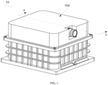
- FIG. 1 is a perspective structural schematic diagram of a battery module 10 according to some embodiments of the present disclosure.
- FIG. 2 is an exploded structural schematic diagram of the battery module 10 in FIG. 1 .
- the battery module 10 in this embodiment includes a plurality of battery cells 10a, a plurality of busbars 13, and a pressure relief bracket assembly 10b.
- FIG. 3 is a schematic cross-sectional view of the battery module 10 in FIG. 1 taken in an F-F direction
- FIG. 4 is a perspective structural schematic diagram of the pressure relief bracket assembly 10b in FIG. 2
- FIG. 5 is an exploded structural schematic diagram of the pressure relief bracket assembly 10b in FIG. 4
- FIG. 6 is a schematic cross-sectional view of the pressure relief bracket assembly 10b in FIG. 3 .
- the pressure relief bracket assembly 10b includes a pressure relief bracket 11 and a protective cover 12.
- One side of the pressure relief bracket 11 facing a first direction A is formed with a plurality of receiving grooves 102 and a plurality of pressure relief ports 103.
- the receiving grooves 102 are configured to install the busbars 13.
- the busbars 13 installed in the plurality of receiving grooves 102 are electrically coupled to the plurality of battery cells 10a respectively. It can be understood that the amount of the receiving grooves 102 and the busbars 13 can be set according to actual needs, which is not limited.
- the protective cover 12 is formed with a substance channel 104.
- the protective cover 12 covers on the pressure relief ports 103, making the substance channel 104 in communication with the pressure relief ports 103, as well as making the protective cover 12 isolate the pressure relief ports 103 from the receiving grooves 102. Therefore, when the battery cells 10a experience thermal runaway, the pressure generated by the thermal runaway is released through the pressure relief ports 103. At the same time, the thermal substances sprayed from the pressure relief ports 103 are discharged into the substance channel 104.
- the thermal substances sprayed from the pressure relief ports 103 are prevented from dispersing onto the busbars 13, thereby avoiding spread of thermal runaway and explosion of the battery module, and reducing potential safety hazards.
- the substance channel 104 extends in a second direction B, which is intersects with the first direction A.
- the second direction B is perpendicular to the first direction A.
- An end portion of the protective cover 12 in the second direction B, that is, an extending direction of the substance channel104, is further formed with a substance discharge outlet 105 that is in communication with the substance channel 104, so that the thermal substances discharged from the pressure relief ports 103 to the substance channel 104 are discharged through the substance discharge outlet 105, preventing thermal substances from accumulating in the substance channel 104.
- the substance discharge outlet 105 is formed on one side of the protective cover 12 away from the pressure relief bracket 11.
- the protective cover 12 is further formed with an exhaust port 106 that is in communication with the substance channel 104.
- the exhaust port 106 is formed at an end of the protective cover 12 opposite to the substance discharge outlet 105, so that when thermal runaway occurs in the battery cells 10a, high-temperature gas generated by the thermal runaway is discharged from the pressure relief ports 103 to the substance channel 104, and then is discharged through the exhaust port 106. That is, the protective cover 12 in this embodiment can not only discharge the thermal substances through the substance discharge outlet 105 provided at one end of the protective cover 12, but also discharge the high-temperature gas through the exhaust port 106 provided at the other end of the protective cover 12. In practical applications, the battery module 10 is placed as shown in FIG. 3 .
- the substance discharge outlet 105 is located at a bottom of the protective cover 12, and the exhaust port 106 is located at a top of the protective cover 12.
- the thermal substances such as electrolyte, sprayed from the pressure relief ports 103 to the substance channel 104 will flow, due to gravity, along the substance channel 104 towards the substance discharge outlet 105 at the bottom, while the high-temperature gas discharged from the pressure relief ports 103 to the substance channel 104 will flow along the substance channel 104 towards the exhaust port 106 at the top.
- the pressure relief bracket 11 is further formed with a wire harness passage 107
- the protective cover 12 is further formed with a wire harness notch 108 that is in communication with the wire harness passage 107, so that collection wire harnesses connected to the busbars 13 are sequentially led out through the wire harness notch 108 and the wire harness passage 107.
- the pressure relief bracket 11 includes a bracket body 111 and a pressure relief body 112.
- the bracket body 111 is formed with the receiving grooves 102.
- the pressure relief body 112 includes a pressure relief portion 1121 and a partition portion 1122.
- the pressure relief portion 1121 is connected with the bracket body 111 and is formed with the pressure relief ports 103.
- the partition portion 1122 is connected with the pressure relief portion 1121, and is spaced apart from the bracket body 111 to form the wire harness passage 107.
- the protective cover 12 covers on the pressure relief portion 1121 and the partition portion 1122, making the wire harness notch 108 in communication with the wire harness passage 107.
- the collection wire harnesses are sequentially led out through the harness notch 108 and the harnesses channels 107, and on the other hand, the collection wire harnesses are separated from the substance channel 104 by the partition portion 1122, so as to avoid damage to the collection wire harnesses caused by the thermal substances.
- the protective cover 12 is detachably mounted on the pressure relief bracket 11.
- the protective cover 12 is provided with a connecting hook 121
- the bracket body 111 is further provided with a connecting groove 1111 corresponding to the connecting hook 121.
- the protective cover 12 is mounted on the pressure relief bracket 11 by an engagement of the connecting hook 121 and the connecting groove 1111.
- the protective cover 12 is further provided with an extending portion 122
- the bracket body 111 is further provided with an inserting slot 1112 corresponding to the extending portion 122 and configured to receive the extending portion 122 of the protective cover 12, so as to improve the stability of the connection between the protective cover 12 and the pressure relief bracket 11.
- At least one side of the bracket body 111 is formed with a plurality of through holes 1113.
- the through holes 1113 are configured to allow glue to be injected into the pressure relief bracket 11 after assembling the plurality of battery cells 10a with the pressure relief bracket 11, thereby achieving bonding between the battery cells 10a and the pressure relief bracket 11.
- the battery module 10 in this embodiment further includes a battery management unit 10c.
- the battery management unit 10c is electrically coupled to the busbars 13.
- the battery management unit 10c is electrically coupled to the busbars 13 through the described collection wire harnesses.
- the battery management unit 10c is arranged on one side of the protective cover 12 away from the pressure relief bracket 11.
- the protective cover 12 isolates the battery management unit 10c from the pressure relief ports 103, preventing the thermal substances sprayed from the pressure relief ports 103 from dispersing onto the battery management unit 10c, thereby avoiding the spread of the thermal runaway and explosion of the battery module 10, and reducing potential safety hazards.
- the battery management unit 10c is arranged on one side of the protective cover 12 away from the pressure relief bracket 11, and as described above, the substance discharge outlet 105 is arranged at the end portion of the protective cover 12 in the second direction B, so that during the process of the thermal substances being sprayed from the pressure discharge ports 103, the thermal substances are blocked by the protective cover 12, and will not be directly sprayed onto the battery management unit 10c through the substance discharge outlet 105.
- FIG. 7 is a schematic cross-sectional view of a shell 10d in FIG. 3 .
- the battery module 10 in this embodiment further includes a shell 10d, which is formed with an accommodating space 109 and a ventilation hole 110 in communication with the accommodating space 109.
- the pressure relief bracket assembly 10b is arranged in the accommodating space 109.
- the ventilation hole 110 is mounted with an explosion-proof valve 115, so that when thermal runaway occurs in the battery cells 10a, the high-temperature gas generated by the thermal runaway is discharged into the accommodating space 109 via the exhaust port 106, and then discharged when the explosion-proof valve 115 is opened.
- the shell 10d includes an upper shell 113 and a lower shell 114.
- the upper shell 113 is formed with a first sub-space 1091
- the lower shell 114 is formed with a second sub-space 1092
- the first sub-space 1091 and the second sub-space 1092 cooperate to form the accommodating space 109.
- the ventilation hole 110 is formed in the upper shell 113 and is in communication with the first sub-space 1091.
- the pressure relief bracket assembly 10b is arranged in the second sub-space 1092.
- the pressure relief bracket assembly 10b includes a pressure relief bracket 11 and a protective cover 12.
- One side of the pressure relief bracket 11 is formed with a plurality of receiving grooves 102 and a plurality of pressure relief ports 103.
- the receiving grooves 102 are configured to install the busbars 13.
- the protective cover 12 is formed with a substance channel 104, where the protective cover 12 covers on the pressure relief ports 103, making the substance channel 104 in communication with the pressure relief port 103, as well as making the protective cover 12 isolate the pressure relief ports 103 from the receiving grooves 102. Therefore, when the battery cells 10a experience thermal runaway, the pressure generated by the thermal runaway is released through the pressure relief ports 103.
- the thermal substances sprayed from the pressure relief ports 103 are discharged into the substance channel 104. Due to the isolation effect of the protective cover 12 on the pressure relief ports 103 and the receiving grooves 102, the thermal substances sprayed from the pressure relief ports 103 are prevented from dispersing onto the busbars 13, thereby avoiding spread of thermal runaway and explosion of the battery module 10, and reducing potential safety hazards.
Landscapes
- Chemical & Material Sciences (AREA)
- Chemical Kinetics & Catalysis (AREA)
- Electrochemistry (AREA)
- General Chemical & Material Sciences (AREA)
- Gas Exhaust Devices For Batteries (AREA)
- Battery Mounting, Suspending (AREA)
- Secondary Cells (AREA)
Abstract
Description
- The present disclosure relates to the technology field of batteries, and in particular, to a pressure relief bracket assembly and a battery module.
- With the rapid development of new energy technologies, battery modules have been widely used in various new energy vehicles and energy storage power stations. The battery module usually includes a plurality of battery cells, which are electrically coupled via a busbar mounted on a cell connection system (CCS) bracket. During the use of the battery module, if phenomena such as short circuits and overshoot occur, a large amount of heat will be accumulated inside the battery cells, resulting in thermal runaway, which may cause an excessively high internal pressure in the battery cells, leading to a fire or even explosion.
- In related technologies, the CCS bracket is generally provided with pressure relief ports to release the pressure generated by thermal runaway. However, in this manner, thermal substances, such as electrolyte, sprayed out from the pressure relief port may fall on the busbar, leading to the spread of thermal runaway in the battery module, causing explosions and causing potential safety hazards.
- In a first aspect, the present disclosure provides a pressure relief bracket assembly. The pressure relief bracket assembly includes a pressure relief bracket and a protective cover. One side of the pressure relief bracketis formed with a plurality of receiving grooves and a plurality of pressure relief ports. The receiving grooves are configured to install busbars. The protective cover is formed with a substance channel, where the protective cover covers on the pressure relief ports, making the substance channel in communication with the pressure relief port, as well as making the protective cover isolate the pressure relief ports from the receiving grooves.
- In a second aspect, the present disclosure provides a battery module. The battery module includes a plurality of battery cells and the pressure relief bracket assembly described above. The receiving grooves are provided with the busbars, which are electrically coupled to the plurality of battery cells.
- The beneficial effects of the pressure relief bracket assembly and the battery module provided in the present disclosure are that: the pressure relief bracket assembly includes a pressure relief bracket and a protective cover. One side of the pressure relief bracket is formed with a plurality of receiving grooves and a plurality of pressure relief ports. The receiving grooves are configured to install the busbars. The protective cover is formed with a substance channel, where the protective cover covers on the pressure relief ports, making the substance channel in communication with the pressure relief port, as well as making the protective cover isolate the pressure relief ports from the receiving grooves. Therefore, when the battery cells experience thermal runaway, the pressure generated by the thermal runaway is released through the pressure relief ports. At the same time, the thermal substances sprayed from the pressure relief ports are discharged into the substance channel. Due to the isolation effect of the protective cover on the pressure relief ports and the receiving grooves, the thermal substances sprayed from the pressure relief ports are prevented from dispersing onto the busbars, thereby avoiding spread of thermal runaway and explosion of the battery module, and reducing potential safety hazards.
-
-
FIG. 1 is a perspective structural schematic diagram of a battery module according to some embodiments. -
FIG. 2 is an exploded structural schematic diagram of the battery module inFIG. 1 . -
FIG. 3 is a schematic cross-sectional view of the battery module inFIG. 1 taken in an F-F direction. -
FIG. 4 is a perspective structural schematic diagram of a pressure relief bracket assembly inFIG. 2 . -
FIG. 5 is an exploded structural schematic diagram of the pressure relief bracket assembly inFIG. 4 . -
FIG 6 is a schematic cross-sectional view of the pressure relief bracket assembly inFIG. 3 . -
FIG. 7 is a schematic cross-sectional view of a shell ofFIG. 3 . - Please refer to
FIG. 1 andFIG. 2 together.FIG. 1 is a perspective structural schematic diagram of abattery module 10 according to some embodiments of the present disclosure.FIG. 2 is an exploded structural schematic diagram of thebattery module 10 inFIG. 1 . Thebattery module 10 in this embodiment includes a plurality ofbattery cells 10a, a plurality ofbusbars 13, and a pressurerelief bracket assembly 10b. - Referring to
FIGs. 3 to 6 together.FIG. 3 is a schematic cross-sectional view of thebattery module 10 inFIG. 1 taken in an F-F direction,FIG. 4 is a perspective structural schematic diagram of the pressurerelief bracket assembly 10b inFIG. 2 ,FIG. 5 is an exploded structural schematic diagram of the pressurerelief bracket assembly 10b inFIG. 4 , andFIG. 6 is a schematic cross-sectional view of the pressurerelief bracket assembly 10b inFIG. 3 . The pressurerelief bracket assembly 10b includes apressure relief bracket 11 and aprotective cover 12. - One side of the
pressure relief bracket 11 facing a first direction A is formed with a plurality of receivinggrooves 102 and a plurality ofpressure relief ports 103. Thereceiving grooves 102 are configured to install thebusbars 13. Thebusbars 13 installed in the plurality of receivinggrooves 102 are electrically coupled to the plurality ofbattery cells 10a respectively. It can be understood that the amount of the receivinggrooves 102 and thebusbars 13 can be set according to actual needs, which is not limited. - The
protective cover 12 is formed with asubstance channel 104. Theprotective cover 12 covers on thepressure relief ports 103, making thesubstance channel 104 in communication with thepressure relief ports 103, as well as making theprotective cover 12 isolate thepressure relief ports 103 from thereceiving grooves 102. Therefore, when thebattery cells 10a experience thermal runaway, the pressure generated by the thermal runaway is released through thepressure relief ports 103. At the same time, the thermal substances sprayed from thepressure relief ports 103 are discharged into thesubstance channel 104. Due to the isolation effect of theprotective cover 12 on thepressure relief ports 103 and the receivinggrooves 102, the thermal substances sprayed from thepressure relief ports 103 are prevented from dispersing onto thebusbars 13, thereby avoiding spread of thermal runaway and explosion of the battery module, and reducing potential safety hazards. - The
substance channel 104 extends in a second direction B, which is intersects with the first direction A. In the present embodiment, the second direction B is perpendicular to the first direction A. An end portion of theprotective cover 12 in the second direction B, that is, an extending direction of the substance channel104, is further formed with asubstance discharge outlet 105 that is in communication with thesubstance channel 104, so that the thermal substances discharged from thepressure relief ports 103 to thesubstance channel 104 are discharged through thesubstance discharge outlet 105, preventing thermal substances from accumulating in thesubstance channel 104. Thesubstance discharge outlet 105 is formed on one side of theprotective cover 12 away from thepressure relief bracket 11. - The
protective cover 12 is further formed with anexhaust port 106 that is in communication with thesubstance channel 104. Theexhaust port 106 is formed at an end of theprotective cover 12 opposite to thesubstance discharge outlet 105, so that when thermal runaway occurs in thebattery cells 10a, high-temperature gas generated by the thermal runaway is discharged from thepressure relief ports 103 to thesubstance channel 104, and then is discharged through theexhaust port 106. That is, theprotective cover 12 in this embodiment can not only discharge the thermal substances through thesubstance discharge outlet 105 provided at one end of theprotective cover 12, but also discharge the high-temperature gas through theexhaust port 106 provided at the other end of theprotective cover 12. In practical applications, thebattery module 10 is placed as shown inFIG. 3 . In this placement state, thesubstance discharge outlet 105 is located at a bottom of theprotective cover 12, and theexhaust port 106 is located at a top of theprotective cover 12. When thermal runaway occurs in thebattery cells 10a, the thermal substances, such as electrolyte, sprayed from thepressure relief ports 103 to thesubstance channel 104 will flow, due to gravity, along thesubstance channel 104 towards thesubstance discharge outlet 105 at the bottom, while the high-temperature gas discharged from thepressure relief ports 103 to thesubstance channel 104 will flow along thesubstance channel 104 towards theexhaust port 106 at the top. - In the present embodiment, the
pressure relief bracket 11 is further formed with awire harness passage 107, and theprotective cover 12 is further formed with awire harness notch 108 that is in communication with thewire harness passage 107, so that collection wire harnesses connected to thebusbars 13 are sequentially led out through thewire harness notch 108 and thewire harness passage 107. - The
pressure relief bracket 11 includes abracket body 111 and apressure relief body 112. Thebracket body 111 is formed with thereceiving grooves 102. Thepressure relief body 112 includes apressure relief portion 1121 and apartition portion 1122. Thepressure relief portion 1121 is connected with thebracket body 111 and is formed with thepressure relief ports 103. Thepartition portion 1122 is connected with thepressure relief portion 1121, and is spaced apart from thebracket body 111 to form thewire harness passage 107. Theprotective cover 12 covers on thepressure relief portion 1121 and thepartition portion 1122, making thewire harness notch 108 in communication with thewire harness passage 107. With this arrangement, on the one hand, the collection wire harnesses are sequentially led out through theharness notch 108 and theharnesses channels 107, and on the other hand, the collection wire harnesses are separated from thesubstance channel 104 by thepartition portion 1122, so as to avoid damage to the collection wire harnesses caused by the thermal substances. - Referring to
FIG. 5 again, in this embodiment, theprotective cover 12 is detachably mounted on thepressure relief bracket 11. For example, theprotective cover 12 is provided with a connectinghook 121, and thebracket body 111 is further provided with a connectinggroove 1111 corresponding to the connectinghook 121. Theprotective cover 12 is mounted on thepressure relief bracket 11 by an engagement of the connectinghook 121 and the connectinggroove 1111. - In this embodiment, the
protective cover 12 is further provided with an extendingportion 122, and thebracket body 111 is further provided with an insertingslot 1112 corresponding to the extendingportion 122 and configured to receive the extendingportion 122 of theprotective cover 12, so as to improve the stability of the connection between theprotective cover 12 and thepressure relief bracket 11. - In this embodiment, at least one side of the
bracket body 111 is formed with a plurality of throughholes 1113. The throughholes 1113 are configured to allow glue to be injected into thepressure relief bracket 11 after assembling the plurality ofbattery cells 10a with thepressure relief bracket 11, thereby achieving bonding between thebattery cells 10a and thepressure relief bracket 11. - Referring to
FIG. 2 andFIG. 3 again, thebattery module 10 in this embodiment further includes abattery management unit 10c. Thebattery management unit 10c is electrically coupled to thebusbars 13. In this embodiment, thebattery management unit 10c is electrically coupled to thebusbars 13 through the described collection wire harnesses. - The
battery management unit 10c is arranged on one side of theprotective cover 12 away from thepressure relief bracket 11. By means of this arrangement, theprotective cover 12 isolates thebattery management unit 10c from thepressure relief ports 103, preventing the thermal substances sprayed from thepressure relief ports 103 from dispersing onto thebattery management unit 10c, thereby avoiding the spread of the thermal runaway and explosion of thebattery module 10, and reducing potential safety hazards. - The
battery management unit 10c is arranged on one side of theprotective cover 12 away from thepressure relief bracket 11, and as described above, thesubstance discharge outlet 105 is arranged at the end portion of theprotective cover 12 in the second direction B, so that during the process of the thermal substances being sprayed from thepressure discharge ports 103, the thermal substances are blocked by theprotective cover 12, and will not be directly sprayed onto thebattery management unit 10c through thesubstance discharge outlet 105. - Referring to
FIGs. 1 to 3 and7 again.FIG. 7 is a schematic cross-sectional view of ashell 10d inFIG. 3 . Thebattery module 10 in this embodiment further includes ashell 10d, which is formed with anaccommodating space 109 and aventilation hole 110 in communication with theaccommodating space 109. The pressurerelief bracket assembly 10b is arranged in theaccommodating space 109. Theventilation hole 110 is mounted with an explosion-proof valve 115, so that when thermal runaway occurs in thebattery cells 10a, the high-temperature gas generated by the thermal runaway is discharged into theaccommodating space 109 via theexhaust port 106, and then discharged when the explosion-proof valve 115 is opened. - The
shell 10d includes anupper shell 113 and alower shell 114. Theupper shell 113 is formed with afirst sub-space 1091, thelower shell 114 is formed with asecond sub-space 1092, and thefirst sub-space 1091 and thesecond sub-space 1092 cooperate to form theaccommodating space 109. Theventilation hole 110 is formed in theupper shell 113 and is in communication with thefirst sub-space 1091. The pressurerelief bracket assembly 10b is arranged in thesecond sub-space 1092. - In the present disclosure, the pressure
relief bracket assembly 10b includes apressure relief bracket 11 and aprotective cover 12. One side of thepressure relief bracket 11 is formed with a plurality of receivinggrooves 102 and a plurality ofpressure relief ports 103. The receivinggrooves 102 are configured to install thebusbars 13. Theprotective cover 12 is formed with asubstance channel 104, where theprotective cover 12 covers on thepressure relief ports 103, making thesubstance channel 104 in communication with thepressure relief port 103, as well as making theprotective cover 12 isolate thepressure relief ports 103 from the receivinggrooves 102. Therefore, when thebattery cells 10a experience thermal runaway, the pressure generated by the thermal runaway is released through thepressure relief ports 103. At the same time, the thermal substances sprayed from thepressure relief ports 103 are discharged into thesubstance channel 104. Due to the isolation effect of theprotective cover 12 on thepressure relief ports 103 and the receivinggrooves 102, the thermal substances sprayed from thepressure relief ports 103 are prevented from dispersing onto thebusbars 13, thereby avoiding spread of thermal runaway and explosion of thebattery module 10, and reducing potential safety hazards.
Claims (15)
- A pressure relief bracket assembly (10b), comprising:a pressure relief bracket (11), wherein one side of the pressure relief bracket (11) is formed with a plurality of receiving grooves (102) and a plurality of pressure relief ports (103); wherein the receiving grooves (102) are configured to install busbars (13);a protective cover (12) formed with a substance channel (104), wherein the protective cover (12) covers on the pressure relief ports (103), making the substance channel (104) in communication with the pressure relief ports (103), as well as making the protective cover (12) isolate the pressure relief ports (103) from the receiving grooves (102).
- The pressure relief bracket assembly (10b) according to claim 1, wherein an end portion of the protective cover (12) in an extending direction of the substance channel (104) is provided with a substance discharge outlet (105) that is in communication with the substance channel (104).
- The pressure relief bracket assembly (10b) according to claim 2, wherein the substance discharge outlet (105) is formed on one side of the protective cover (12) away from the pressure relief bracket (11).
- The pressure relief bracket assembly (10b) according to claim 2, wherein the protective cover (12) is further formed with an exhaust port (106) that is in communication with the substance channel (104); wherein the exhaust port (106) is formed at an end of the protective cover (12) opposite to the substance discharge outlet (105).
- The pressure relief bracket assembly (10b) according to claim 1, wherein the pressure relief bracket (11) is further provided with a wire harness passage (107), and the protective cover (12) is further provided with a wire harness notch (108) that is in communication with the wire harness passage (107).
- The pressure relief bracket assembly (10b) according to claim 5, wherein the pressure relief bracket (11) comprises a bracket body (111) and a pressure relief body (112); wherein the bracket body (111) is formed with the receiving grooves (102); the pressure relief body (112) comprises a pressure relief portion (1121) and a partition portion (1122); wherein the pressure relief portion (1121) is connected to the bracket body (111) and is formed with the pressure relief ports (103); the partition portion (1122) is connected with the pressure relief portion (1121), and is spaced apart from the bracket body (111) to form the wire harness passage (107); the protective cover (12) covers on the pressure relief portion (1121) and the partition portion (1122), making the wire harness notch (108) in communication with the wire harness passage (107).
- The pressure relief bracket assembly (10b) according to claim 1, wherein the protective cover (12) is detachably mounted on the pressure relief bracket (11).
- The pressure relief bracket assembly (10b) according to claim 7, wherein the pressure relief bracket (11) comprises a bracket body (111), wherein the protective cover (12) is provided with a connecting hook (121), and the bracket body (111) is provided with a connecting groove (1111) corresponding to the connecting hook (121); wherein the protective cover (12) is mounted on the pressure relief bracket (11) by an engagement of the connecting hook (121) and the connecting groove (1111).
- The pressure relief bracket assembly (10b) according to claim 8, wherein the protective cover (12) is further provided with an extending portion (122), and the bracket body (111) is further provided with an inserting slot (1112) corresponding to the extending portion (122) and configured to receive the extending portion (122) of the protective cover (12).
- The pressure relief bracket assembly (10b) according to claim 1, wherein at least one side of the bracket body (111) is formed with a plurality of through holes (1113), wherein the through holes (1113) are configured to allow glue to be injected into the pressure relief bracket (11) after assembling a plurality of battery cells with the pressure relief bracket (11), thereby achieving bonding between the battery cells and the pressure relief bracket (11).
- A battery module (10) comprising a plurality of battery cells (10a), a plurality of busbars (13), and the pressure relief bracket assembly (10b) according to any one of claims 1 to 9, wherein the receiving grooves (102) are provided with the busbars (13), and the busbars (13) installed in the plurality of receiving grooves (102) are electrically coupled to the plurality of battery cells (10a) respectively.
- The battery module (10) according to claim 11, further comprising a battery management unit (10c), wherein the battery management unit (10c) is electrically coupled to the busbars (13) and is arranged on one side of the protective cover (12) away from the pressure relief bracket (11).
- The battery module (10) according to claim 11, further comprising a shell (10d), wherein the shell (10d) is formed with an accommodating space (109) and a ventilation hole (110) in communication with the accommodating space (109); the pressure relief bracket assembly (10b) is arranged in the accommodating space (109); and the ventilation hole (110) is mounted with an explosion-proof valve (115).
- The battery module (10) according to claim 13, wherein the shell (10d) comprises an upper shell (113) and a lower shell (114); the upper shell (113) is formed with a first sub-space (1091), the lower shell (114) is formed with a second sub-space (1092), and the first sub-space (1091) and the second sub-space (1092) cooperate to form the accommodating space (109); the ventilation hole (110) is formed in the upper shell (113) and is in communication with the first sub-space (1091); the pressure relief bracket assembly (10b) is arranged in the second sub-space (1092).
- The battery module (10) according to claim 11, wherein at least one side of the bracket body (111) is formed with a plurality of through holes (1113), wherein the through holes (1113) are configured to allow glue to be injected into the pressure relief bracket (11) after assembling a plurality of battery cells (10a) with the pressure relief bracket (11), thereby achieving bonding between the battery cells (10a) and the pressure relief bracket (11).
Applications Claiming Priority (1)
| Application Number | Priority Date | Filing Date | Title |
|---|---|---|---|
| CN202323404386.6U CN222507893U (en) | 2023-12-13 | 2023-12-13 | Pressure release bracket component and battery module |
Publications (2)
| Publication Number | Publication Date |
|---|---|
| EP4571971A2 true EP4571971A2 (en) | 2025-06-18 |
| EP4571971A3 EP4571971A3 (en) | 2025-07-23 |
Family
ID=93150236
Family Applications (1)
| Application Number | Title | Priority Date | Filing Date |
|---|---|---|---|
| EP24206735.3A Pending EP4571971A3 (en) | 2023-12-13 | 2024-10-15 | Pressure relief bracket assembly and battery module |
Country Status (4)
| Country | Link |
|---|---|
| US (1) | US20250202036A1 (en) |
| EP (1) | EP4571971A3 (en) |
| CN (1) | CN222507893U (en) |
| WO (1) | WO2025123767A1 (en) |
Family Cites Families (17)
| Publication number | Priority date | Publication date | Assignee | Title |
|---|---|---|---|---|
| US9614208B2 (en) * | 2011-10-10 | 2017-04-04 | Samsung Sdi Co., Ltd. | Battery pack with degassing cover and plate thereon |
| JP6182374B2 (en) * | 2013-07-12 | 2017-08-16 | 矢崎総業株式会社 | Power supply |
| KR20150066077A (en) * | 2013-12-06 | 2015-06-16 | 삼성에스디아이 주식회사 | Battery module |
| KR101720618B1 (en) * | 2013-12-17 | 2017-03-28 | 삼성에스디아이 주식회사 | Battery module having bus bar holder |
| KR102248596B1 (en) * | 2014-04-11 | 2021-05-06 | 삼성에스디아이 주식회사 | Battery module |
| JP2016046163A (en) * | 2014-08-25 | 2016-04-04 | 三菱重工業株式会社 | Battery module and module cover |
| JP6633989B2 (en) * | 2016-07-29 | 2020-01-22 | 矢崎総業株式会社 | Battery pack |
| CN214313451U (en) * | 2020-11-25 | 2021-09-28 | 北京车和家信息技术有限公司 | Busbar, fire prevention end cover, battery module and vehicle |
| CN215578941U (en) * | 2021-05-18 | 2022-01-18 | 湖北亿纬动力有限公司 | Battery module thermal runaway protective structure |
| US11799162B2 (en) * | 2021-08-18 | 2023-10-24 | Rolls-Royce Singapore Pte. Ltd. | Light weight thermal runaway and explosion resistant aerospace battery |
| CN216084988U (en) * | 2021-09-09 | 2022-03-18 | 苏州联胜新能源科技有限公司 | Highly integrated lithium ion battery module |
| CN217426916U (en) * | 2022-04-06 | 2022-09-13 | 无锡力多仕新能源科技有限公司 | Battery cell protective cover |
| CN218385368U (en) * | 2022-09-30 | 2023-01-24 | 阿特斯储能科技有限公司 | Battery module and liquid-cooling energy storage battery pack system with same |
| CN219917451U (en) * | 2023-05-18 | 2023-10-27 | 江苏正力新能电池技术有限公司 | Battery module, battery and electric equipment |
| CN116960579B (en) * | 2023-09-18 | 2024-01-26 | 厦门海辰储能科技股份有限公司 | A battery module and electrical equipment |
| CN117117427A (en) * | 2023-09-20 | 2023-11-24 | 厦门海辰储能科技股份有限公司 | Wire harness isolation board, battery module, energy storage device and electric equipment |
| CN117175043B (en) * | 2023-10-17 | 2024-01-26 | 厦门海辰储能科技股份有限公司 | Battery modules, energy storage devices and electrical equipment |
-
2023
- 2023-12-13 CN CN202323404386.6U patent/CN222507893U/en active Active
-
2024
- 2024-08-22 WO PCT/CN2024/113982 patent/WO2025123767A1/en active Pending
- 2024-10-15 EP EP24206735.3A patent/EP4571971A3/en active Pending
- 2024-11-18 US US18/951,555 patent/US20250202036A1/en active Pending
Also Published As
| Publication number | Publication date |
|---|---|
| US20250202036A1 (en) | 2025-06-19 |
| CN222507893U (en) | 2025-02-18 |
| WO2025123767A1 (en) | 2025-06-19 |
| EP4571971A3 (en) | 2025-07-23 |
Similar Documents
| Publication | Publication Date | Title |
|---|---|---|
| CN217182360U (en) | Smoke exhaust system for energy storage device, energy storage device and power utilization device | |
| CN116231211B (en) | A battery box and system capable of being stacked in multiple layers | |
| CN223502114U (en) | Exhaust components, housing, battery and electrical devices | |
| CN221262603U (en) | Battery and electric equipment | |
| WO2025118435A1 (en) | Battery and electric device | |
| CN212323136U (en) | Battery | |
| EP4571971A2 (en) | Pressure relief bracket assembly and battery module | |
| CN120184537B (en) | Battery modules, energy storage devices and electrical equipment | |
| CN221262631U (en) | Batteries and electrical equipment | |
| EP4625652A1 (en) | Pressure relief structure for double-layer battery and battery pack | |
| CN220774617U (en) | Battery and power-using device | |
| CN220753654U (en) | Novel battery pack structure | |
| CN219436000U (en) | Battery and electricity utilization device | |
| CN117175107A (en) | A battery box, a battery pack and a battery pack assembling method | |
| CN223843074U (en) | Battery device, energy storage device, electricity utilization device and charging network | |
| CN224021019U (en) | Battery cells, battery packs, and electrical devices | |
| CN116073062A (en) | Explosion-proof valve for power battery and power battery | |
| CN119725919B (en) | Battery pack and electric equipment | |
| CN224006014U (en) | Battery pack components and electrical equipment | |
| CN224096830U (en) | A battery box and an energy storage system thereon | |
| CN222355374U (en) | Battery module, battery pack and energy storage system | |
| CN223625162U (en) | Battery pack and electric equipment | |
| CN223079293U (en) | Battery Pack | |
| CN223502117U (en) | A battery cell, battery pack and vehicle | |
| CN223941950U (en) | Battery pack |
Legal Events
| Date | Code | Title | Description |
|---|---|---|---|
| PUAI | Public reference made under article 153(3) epc to a published international application that has entered the european phase |
Free format text: ORIGINAL CODE: 0009012 |
|
| STAA | Information on the status of an ep patent application or granted ep patent |
Free format text: STATUS: REQUEST FOR EXAMINATION WAS MADE |
|
| 17P | Request for examination filed |
Effective date: 20241015 |
|
| AK | Designated contracting states |
Kind code of ref document: A2 Designated state(s): AL AT BE BG CH CY CZ DE DK EE ES FI FR GB GR HR HU IE IS IT LI LT LU LV MC ME MK MT NL NO PL PT RO RS SE SI SK SM TR |
|
| PUAL | Search report despatched |
Free format text: ORIGINAL CODE: 0009013 |
|
| AK | Designated contracting states |
Kind code of ref document: A3 Designated state(s): AL AT BE BG CH CY CZ DE DK EE ES FI FR GB GR HR HU IE IS IT LI LT LU LV MC ME MK MT NL NO PL PT RO RS SE SI SK SM TR |
|
| RIC1 | Information provided on ipc code assigned before grant |
Ipc: H01M 50/209 20210101AFI20250619BHEP Ipc: H01M 50/271 20210101ALI20250619BHEP Ipc: H01M 50/358 20210101ALI20250619BHEP Ipc: H01M 50/507 20210101ALI20250619BHEP |