EP4571966A1 - Battery pack - Google Patents
Battery pack Download PDFInfo
- Publication number
- EP4571966A1 EP4571966A1 EP23852457.3A EP23852457A EP4571966A1 EP 4571966 A1 EP4571966 A1 EP 4571966A1 EP 23852457 A EP23852457 A EP 23852457A EP 4571966 A1 EP4571966 A1 EP 4571966A1
- Authority
- EP
- European Patent Office
- Prior art keywords
- sealing member
- battery pack
- storage space
- partition wall
- storage body
- Prior art date
- Legal status (The legal status is an assumption and is not a legal conclusion. Google has not performed a legal analysis and makes no representation as to the accuracy of the status listed.)
- Pending
Links
Images



Classifications
-
- H—ELECTRICITY
- H01—ELECTRIC ELEMENTS
- H01M—PROCESSES OR MEANS, e.g. BATTERIES, FOR THE DIRECT CONVERSION OF CHEMICAL ENERGY INTO ELECTRICAL ENERGY
- H01M50/00—Constructional details or processes of manufacture of the non-active parts of electrochemical cells other than fuel cells, e.g. hybrid cells
- H01M50/20—Mountings; Secondary casings or frames; Racks, modules or packs; Suspension devices; Shock absorbers; Transport or carrying devices; Holders
- H01M50/244—Secondary casings; Racks; Suspension devices; Carrying devices; Holders characterised by their mounting method
-
- H—ELECTRICITY
- H01—ELECTRIC ELEMENTS
- H01M—PROCESSES OR MEANS, e.g. BATTERIES, FOR THE DIRECT CONVERSION OF CHEMICAL ENERGY INTO ELECTRICAL ENERGY
- H01M50/00—Constructional details or processes of manufacture of the non-active parts of electrochemical cells other than fuel cells, e.g. hybrid cells
- H01M50/20—Mountings; Secondary casings or frames; Racks, modules or packs; Suspension devices; Shock absorbers; Transport or carrying devices; Holders
- H01M50/204—Racks, modules or packs for multiple batteries or multiple cells
-
- H—ELECTRICITY
- H01—ELECTRIC ELEMENTS
- H01M—PROCESSES OR MEANS, e.g. BATTERIES, FOR THE DIRECT CONVERSION OF CHEMICAL ENERGY INTO ELECTRICAL ENERGY
- H01M50/00—Constructional details or processes of manufacture of the non-active parts of electrochemical cells other than fuel cells, e.g. hybrid cells
- H01M50/20—Mountings; Secondary casings or frames; Racks, modules or packs; Suspension devices; Shock absorbers; Transport or carrying devices; Holders
- H01M50/262—Mountings; Secondary casings or frames; Racks, modules or packs; Suspension devices; Shock absorbers; Transport or carrying devices; Holders with fastening means, e.g. locks
-
- H—ELECTRICITY
- H01—ELECTRIC ELEMENTS
- H01M—PROCESSES OR MEANS, e.g. BATTERIES, FOR THE DIRECT CONVERSION OF CHEMICAL ENERGY INTO ELECTRICAL ENERGY
- H01M50/00—Constructional details or processes of manufacture of the non-active parts of electrochemical cells other than fuel cells, e.g. hybrid cells
- H01M50/20—Mountings; Secondary casings or frames; Racks, modules or packs; Suspension devices; Shock absorbers; Transport or carrying devices; Holders
- H01M50/271—Lids or covers for the racks or secondary casings
-
- H—ELECTRICITY
- H01—ELECTRIC ELEMENTS
- H01M—PROCESSES OR MEANS, e.g. BATTERIES, FOR THE DIRECT CONVERSION OF CHEMICAL ENERGY INTO ELECTRICAL ENERGY
- H01M50/00—Constructional details or processes of manufacture of the non-active parts of electrochemical cells other than fuel cells, e.g. hybrid cells
- H01M50/20—Mountings; Secondary casings or frames; Racks, modules or packs; Suspension devices; Shock absorbers; Transport or carrying devices; Holders
- H01M50/289—Mountings; Secondary casings or frames; Racks, modules or packs; Suspension devices; Shock absorbers; Transport or carrying devices; Holders characterised by spacing elements or positioning means within frames, racks or packs
- H01M50/291—Mountings; Secondary casings or frames; Racks, modules or packs; Suspension devices; Shock absorbers; Transport or carrying devices; Holders characterised by spacing elements or positioning means within frames, racks or packs characterised by their shape
-
- H—ELECTRICITY
- H01—ELECTRIC ELEMENTS
- H01M—PROCESSES OR MEANS, e.g. BATTERIES, FOR THE DIRECT CONVERSION OF CHEMICAL ENERGY INTO ELECTRICAL ENERGY
- H01M50/00—Constructional details or processes of manufacture of the non-active parts of electrochemical cells other than fuel cells, e.g. hybrid cells
- H01M50/30—Arrangements for facilitating escape of gases
- H01M50/35—Gas exhaust passages comprising elongated, tortuous or labyrinth-shaped exhaust passages
- H01M50/367—Internal gas exhaust passages forming part of the battery cover or case; Double cover vent systems
-
- H—ELECTRICITY
- H01—ELECTRIC ELEMENTS
- H01M—PROCESSES OR MEANS, e.g. BATTERIES, FOR THE DIRECT CONVERSION OF CHEMICAL ENERGY INTO ELECTRICAL ENERGY
- H01M50/00—Constructional details or processes of manufacture of the non-active parts of electrochemical cells other than fuel cells, e.g. hybrid cells
- H01M50/30—Arrangements for facilitating escape of gases
- H01M50/394—Gas-pervious parts or elements
-
- B—PERFORMING OPERATIONS; TRANSPORTING
- B60—VEHICLES IN GENERAL
- B60L—PROPULSION OF ELECTRICALLY-PROPELLED VEHICLES; SUPPLYING ELECTRIC POWER FOR AUXILIARY EQUIPMENT OF ELECTRICALLY-PROPELLED VEHICLES; ELECTRODYNAMIC BRAKE SYSTEMS FOR VEHICLES IN GENERAL; MAGNETIC SUSPENSION OR LEVITATION FOR VEHICLES; MONITORING OPERATING VARIABLES OF ELECTRICALLY-PROPELLED VEHICLES; ELECTRIC SAFETY DEVICES FOR ELECTRICALLY-PROPELLED VEHICLES
- B60L50/00—Electric propulsion with power supplied within the vehicle
- B60L50/50—Electric propulsion with power supplied within the vehicle using propulsion power supplied by batteries or fuel cells
- B60L50/60—Electric propulsion with power supplied within the vehicle using propulsion power supplied by batteries or fuel cells using power supplied by batteries
- B60L50/64—Constructional details of batteries specially adapted for electric vehicles
-
- H—ELECTRICITY
- H01—ELECTRIC ELEMENTS
- H01M—PROCESSES OR MEANS, e.g. BATTERIES, FOR THE DIRECT CONVERSION OF CHEMICAL ENERGY INTO ELECTRICAL ENERGY
- H01M2220/00—Batteries for particular applications
- H01M2220/20—Batteries in motive systems, e.g. vehicle, ship, plane
-
- H—ELECTRICITY
- H01—ELECTRIC ELEMENTS
- H01M—PROCESSES OR MEANS, e.g. BATTERIES, FOR THE DIRECT CONVERSION OF CHEMICAL ENERGY INTO ELECTRICAL ENERGY
- H01M50/00—Constructional details or processes of manufacture of the non-active parts of electrochemical cells other than fuel cells, e.g. hybrid cells
- H01M50/20—Mountings; Secondary casings or frames; Racks, modules or packs; Suspension devices; Shock absorbers; Transport or carrying devices; Holders
- H01M50/249—Mountings; Secondary casings or frames; Racks, modules or packs; Suspension devices; Shock absorbers; Transport or carrying devices; Holders specially adapted for aircraft or vehicles, e.g. cars or trains
-
- Y—GENERAL TAGGING OF NEW TECHNOLOGICAL DEVELOPMENTS; GENERAL TAGGING OF CROSS-SECTIONAL TECHNOLOGIES SPANNING OVER SEVERAL SECTIONS OF THE IPC; TECHNICAL SUBJECTS COVERED BY FORMER USPC CROSS-REFERENCE ART COLLECTIONS [XRACs] AND DIGESTS
- Y02—TECHNOLOGIES OR APPLICATIONS FOR MITIGATION OR ADAPTATION AGAINST CLIMATE CHANGE
- Y02E—REDUCTION OF GREENHOUSE GAS [GHG] EMISSIONS, RELATED TO ENERGY GENERATION, TRANSMISSION OR DISTRIBUTION
- Y02E60/00—Enabling technologies; Technologies with a potential or indirect contribution to GHG emissions mitigation
- Y02E60/10—Energy storage using batteries
Definitions
- the present invention relates to a battery pack.
- the battery pack includes at least one battery module and a storage body storing the at least one module.
- Patent Document 1 describes one example of a battery pack.
- a storage body incudes a battery tray and a battery cover.
- the battery tray and the battery cover are attached to each other via a sealing member.
- Patent Document 2 describes one example of a battery pack.
- a storage body includes a main body portion and a lid portion.
- the main body portion and the lid portion are joined to each other in a joining portion.
- the joining portion the main body portion and the lid portion are welded to each other.
- a storage space of a storage body may be surrounded by a sealing member. This case may require improvement of sealing of the storage space of the storage body.
- One example of an object of the aspect 1 according to the present invention is to improve sealing of a storage space of a storage body. Another object of the aspect 1 according to the present invention may be apparent from description of the present specification.
- a storage space of a storage body may be surrounded by a sealing member.
- This case may require improvement of sealing of the storage space of the storage body.
- the sealing member is preferably positioned accurately to improve sealing of the storage space. It may be, however, difficult to accurately position the sealing member simply by disposing the sealing member.
- One example of an object of the aspect 2 according to the present invention is to improve sealing of a storage space of a storage body. Another object of the aspect 2 according to the present invention may be apparent from description of the present specification.
- the aspect 1 according to the present invention is as described below.
- the aspect 2 according to the present invention is as described below.
- sealing of a storage space of a storage body is improved.
- sealing of a storage space of a storage body is improved.
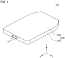
- Fig. 1 is a perspective view of a battery pack 10A according to the embodiment 1.
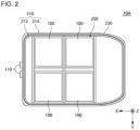
- Fig. 2 is a plan view of the battery pack 10A according to the embodiment 1 with an upper case 220 removed.
- the battery pack 10A is mounted on an automobile. Specifically, the battery pack 10A is mounted between a front wheel and a rear wheel of the automobile.
- the battery pack 10A is described as being mounted on an automobile. However, the battery pack 10A is applicable to an application for other than an automobile.
- the X direction indicates a front-rear direction of the battery pack 10A.
- the Y direction is orthogonal to the X direction.
- the Y direction indicates a left-right direction of the battery pack 10A.
- the Z direction is orthogonal to both of the X direction and the Y direction.
- the Z direction indicates a vertical direction of the battery pack 10A.
- An arrow indicating the X direction and arrows indicating the Y direction and indicating the Z direction indicate a front direction, a left direction, and an upper direction of the battery pack 10A respectively.
- a white circle with a black dot indicating the Z direction indicates that an arrow indicating the Z direction extends from back to front of a surface of paper.
- a relation between the X direction, the Y direction, and the Z direction, and the front-rear direction, the left-right direction, and the vertical direction of the battery pack 10A is not limited to this example.
- the front-rear direction, the left-right direction, and the vertical direction of the battery pack 10A are determined by an automobile mounted with the battery pack 10A.
- the X direction, the Y direction, and the Z direction indicate a front-rear direction, a left-right direction, and a vertical direction of the automobile respectively.
- the arrow indicating the X direction, the arrow indicating the Y direction, and the arrow indicating the Z direction indicate a front direction, a left direction, and an upper direction of the automobile respectively.
- the relation between the front-rear direction, the left-right direction, and the vertical direction of the battery pack 10A, and the front-rear direction, the left-right direction, and the vertical direction of the automobile is not limited to this example.
- a direction perpendicular to the Z direction is referred to as a horizontal direction as necessary.
- the battery pack 10A includes four battery modules 100 and a storage body 200.
- the four battery modules 100 include a pair of battery modules 100 on a left side arranged in the X direction and a pair of battery modules 100 on a right side arranged in the X direction.
- the storage body 200 includes a lower case 210 and an upper case 220.
- the lower case 210 may be generally referred to, for example, as a tray or a main body portion.
- the lower case 210 includes a lower plate 212 and a side frame 214.
- the upper case 220 may be generally referred to, for example, as a cover or a lid portion.
- Each battery module 100 includes a plurality of battery cells stacked in the horizontal direction.
- a plurality of battery cell groups each including a plurality of battery cells connected in parallel is connected in series.
- a plurality of single battery cells may be connected in series.
- the front side of the side frame 214 is provided with a pair of terminals 110.
- the pair of terminals 110 is arranged substantially parallel to the Y direction.
- the front end portion of each terminal 110 protrudes forward from the front surface of the side frame 214.
- the four battery modules 100 are connected in series between the pair of terminals 110.
- the lower case 210 and the upper case 220 are attached to each other via a sealing member 230.
- the lower case 210, the upper case 220, and the sealing member 230 form a storage space 250.
- the four battery modules 100 are stored in the storage space 250.
- the lower plate 212 defines a bottom portion of the storage space 250.
- the side frame 214 defines a side portion of the storage space 250. Specifically, as viewed from the Z direction, the side frame 214 is provided along the outermost circumference of the lower plate 212.
- the upper case 220 defines a top portion of the storage space 250.
- the sealing member 230 is, for example, an elastic material such as rubber. As viewed from the Z direction, the sealing member 230 is provided over the entire circumference of the side frame 214. Thereby, as viewed from the Z direction, the sealing member 230 surrounds the storage space 250. The storage space 250 can be therefore sealed by the sealing member 230 from the external space of the storage body 200.
- the number of and arrangement of the battery modules are not limited to the example according to the embodiment 1.
- the number of battery modules 100 may be, for example, only two, only three, or five or more.
- Fig. 3 is an enlarged plan view of a part of the side frame 214 according to the embodiment 1.
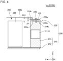
- Fig. 4 is an A-A cross-sectional view of Fig. 3 .
- Fig. 5 is an enlarged view of a part of Fig. 4 .
- the battery module 100, the lower plate 212, and the upper case 220 illustrated in Fig. 4 are not illustrated.
- a pressure release valve 214f illustrated in Fig. 3 is not illustrated.
- a white circle with a black dot indicating the Z direction indicates that an arrow indicating the Z direction extends from back to front of the surface of paper.
- a white circle with X indicating the X direction indicates that an arrow indicating the X direction extends from front to back of the surface of paper.
- the side frame 214 includes a lower attachment portion 214a, a partition wall 214b, and a projected portion 214c.
- the upper case 220 includes an upper attachment portion 220a, an upper cover portion 220b, and a side cover portion 220c.
- the lower attachment portion 214a and the upper attachment portion 220a are attached to each other via the sealing member 230.
- the lower attachment portion 214a is at least a part of the upper surface of the side frame 214.
- the upper attachment portion 220a is at least a part of the outer circumference portion of the upper case 220.
- the lower attachment portion 214a and the upper attachment portion 220a are fixed to each other by a plurality of fasteners 240.
- the plurality of fasteners 240 is disposed in a predetermined interval over the entire circumference of the side frame 214. As illustrated in Fig.
- each fastener 240 is fastened to the lower attachment portion 214a through the upper attachment portion 220a and the sealing member 230 substantially in parallel to the Z direction.
- each fastener 240 is a bolt.
- each fastener 240 may be a fastener other than a bolt.
- gas may be generated from the battery module 100.
- a gas discharge path 214d is provided inside the side frame 214.
- the gas discharge path 214d is hollow.
- the inside surface of the side frame 214 is provided with a plurality of gas discharge holes 214e.
- the plurality of gas discharge holes 214e is disposed in a predetermined interval over the entire circumference of the side frame 214.
- the storage space 250 and the gas discharge path 214d communicate with each other via the plurality of gas discharge holes 214e.
- the pressure release valve 214f is provided on a part of the outside surface of the side frame 214. Accordingly, the gas generated from the battery module 100 in the storage space 250 can be discharged from the pressure release valve 214f through the gas discharge hole 214e and the gas discharge path 214d to the outside of the storage body 200.
- the upper cover portion 220b is surrounded by the upper attachment portion 220a.
- the upper cover portion 220b covers the storage space 250 from above.
- the partition wall 214b protrudes upward from the lower attachment portion 214a. As illustrated in Fig. 4 , the partition wall 214b is provided on the inside end portion of the lower attachment portion 214a. Thereby, the partition wall 214b is located between the battery module 100 and the sealing member 230. For this reason, the partition wall 214b can separate the battery module 100 and the sealing member 230 from each other. As illustrated in Fig. 3 , as viewed from the Z direction, the partition wall 214b continuously extends over the entire circumference of the side frame 214. However, the partition wall 214b may be partially lacked in the entire circumference of the side frame 214.
- the partition wall 214b is located at a higher elevation than the upper surface of the battery module 100.
- the upper surface of the partition wall 214b is located at a higher elevation than the upper surface of the battery module 100 by a height ⁇ H1.
- the partition wall 214b can function as at least a portion of a structure for inhibiting the high-temperature gas from being directly expelled to the sealing member 230.
- breakage of the sealing member 230 caused by direct ejection of the high-temperature gas to the sealing member 230 can be reduced. For this reason, the sealing of the storage space 250 can be improved in the embodiment 1.
- the partition wall 214b is located at a higher elevation than the upper surface of the sealing member 230.
- the upper surface of the partition wall 214b is located at a higher elevation than the upper surface of the sealing member 230 by a height ⁇ h.
- the partition wall 214b can easily function as at least a portion of a structure for inhibiting the above-described high-temperature gas from being directly expelled to the sealing member 230.
- the embodiment 1 can accordingly reduce breakage of the sealing member 230 caused by direct expulsion of the high-temperature gas to the sealing member 230. For this reason, the sealing of the storage space 250 can be improved in the embodiment 1.
- the partition wall 214b is disposed above each gas discharge hole 214e.
- the above-described high-temperature gas is likely to be expelled toward the gas discharge hole 214e or toward an upper side of the gas discharge hole 214e.
- the partition wall 214b can inhibit the high-temperature gas from being directly expelled to the sealing member 230 even if the high-temperature gas is expelled toward the upper side of the gas discharge hole 214e.
- a partition wall located between the battery module 100 and the sealing member 230 is not limited to the partition wall 214b according to the embodiment 1.
- the partition wall 214b is a part of the lower case 210.
- the partition wall may be a part of the upper case 220.
- the partition wall may be a member independent of the storage body 200.
- the side cover portion 220c is provided on an outer edge of the upper attachment portion 220a. As illustrated in Fig. 4 , the lower end of the side cover portion 220c protrudes downward from the outer edge of the upper attachment portion 220a.
- the side cover portion 220c covers a surface of the sealing member 230 on the opposite side of the storage space 250. In the example illustrated in Fig. 4 , the lower end of the side cover portion 220c is located at a lower elevation than the upper end of the partition wall 214b. The lower end of the side cover portion 220c is located on the outside of the outer edge of the upper attachment portion 220a.
- the side cover portion 220c is located at a lower elevation than the lower surface of the sealing member 230.
- the lower end of the side cover portion 220c is located at a lower elevation than the lower surface of the sealing member 230 by a height ⁇ H2.
- the side cover portion 220c can function as at least a portion of a structure for inhibiting the water from being directly expelled to the sealing member 230.
- the embodiment 1 can accordingly reduce breakage of the sealing member 230 caused by direct expulsion of the water to the sealing member 230. For this reason, the sealing of the storage space 250 can be improved in the embodiment 1.
- the projected portion 214c is located below the side cover portion 220c.
- the projected portion 214c projects outward more than the side cover portion 220c.
- the projected portion 214c continuously extends over the entire circumference of the side frame 214.
- the projected portion 214c may be partially lacked in the entire circumference of the side frame 214.
- the projected portion 214c can function as at least a portion of a structure for inhibiting the water from being directly expelled to the sealing member 230.
- the sealing member 230 and the projected portion 214c are separated from each other via at least a portion of the side cover portion 220c. Specifically, as illustrated in Fig. 5 , a virtual line L between the outermost corner of the lower attachment portion 124a and the outermost corner of the projected portion 214c intersects with the side cover portion 220c. Under a predetermined condition such as washing of an automobile mounted with the battery pack 10A, there is a possibility that high-pressure water is expelled along the virtual line L from the outside of the storage body 200. According to the embodiment 1, the projected portion 214c and the side cover portion 220c can function as at least a portion of a structure for inhibiting the water from being directly expelled to the sealing member 230. The embodiment 1 can accordingly reduce breakage of the sealing member 230 caused by direct expulsion of the water to the sealing member 230. For this reason, the sealing of the storage space 250 can be improved in the embodiment 1.
- a cover portion covering a surface of the sealing member 230 on the opposite side of the storage space 250 is not limited to the side cover portion 220c according to the embodiment 1.
- the side cover portion 220c is a part of the upper case 220.
- the cover portion may be a part of the lower case 210.
- the cover portion may be a member independent of the storage body 200.
- a projected portion projecting outward more than the side cover portion 220c is not limited to the projected portion 214c according to the embodiment 1.
- the projected portion 214c is a part of the lower case 210.
- the projected portion may be a part of the upper case 220.
- the projected portion may be a member independent of the storage body 200.
- Fig. 6 is a perspective view of a battery pack 10B according to the embodiment 2.
- Fig. 7 is a plan view of the battery pack 10B according to the embodiment 2 with an upper case 220 removed.
- the battery pack 10B is mounted on an automobile. Specifically, the battery pack 10B is mounted between a front wheel and a rear wheel of the automobile.
- the battery pack 10B is described as being mounted on an automobile. However, the battery pack 10B is applicable to an application for other than an automobile.
- the X direction indicates a front-rear direction of the battery pack 10B.
- the Y direction is orthogonal to the X direction.
- the Y direction indicates a left-right direction of the battery pack 10B.
- the Z direction is orthogonal to both of the X direction and the Y direction.
- the Z direction indicates a vertical direction of the battery pack 10B.
- An arrow indicating the X direction and arrows indicating the Y direction and indicating the Z direction indicate a front direction, a left direction, and an upper direction of the battery pack 10B respectively.
- a white circle with a black dot indicating the Z direction indicates that an arrow indicating the Z direction extends from back to front of a surface of paper.
- a relation between the X direction, the Y direction, and the Z direction, and the front-rear direction, the left-right direction, and the vertical direction of the battery pack 10B is not limited to this example.
- the front-rear direction, the left-right direction, and the vertical direction of the battery pack 10B are determined by an automobile mounted with the battery pack 10B.
- the X direction, the Y direction, and the Z direction indicate a front-rear direction, a left-right direction, and a vertical direction of the automobile respectively.
- the arrow indicating the X direction, the arrow indicating the Y direction, and the arrow indicating the Z direction indicate a front direction, a left direction, and an upper direction of the automobile respectively.
- the relation between the front-rear direction, the left-right direction, and the vertical direction of the battery pack 10B, and the front-rear direction, the left-right direction, and the vertical direction of the automobile is not limited to this example.
- a direction perpendicular to the Z direction is referred to as a horizontal direction as necessary.
- the battery pack 10B includes four battery modules 100 and a storage body 200.
- the four battery modules 100 include a pair of battery modules 100 on a left side arranged in the X direction and a pair of battery modules 100 on a right side arranged in the X direction.
- the storage body 200 includes a lower case 210 and an upper case 220.
- the lower case 210 may be generally referred to, for example, as a tray or a main body portion.
- the lower case 210 includes a lower plate 212 and a side frame 214.
- the upper case 220 may be generally referred to, for example, as a cover or a lid portion.
- Each battery module 100 includes a plurality of battery cells stacked in the horizontal direction.
- a plurality of battery cell groups each including a plurality of battery cells connected in parallel is connected in series.
- a plurality of single battery cells may be connected in series.
- the front side of the side frame 214 is provided with a pair of terminals 110.
- the pair of terminals 110 is arranged substantially parallel to the Y direction.
- the front end portion of each terminal 110 protrudes forward from the front surface of the side frame 214.
- the four battery modules 100 are connected in series between the pair of terminals 110.
- the lower case 210 and the upper case 220 are attached to each other via a sealing member 230.
- the lower case 210, the upper case 220, and the sealing member 230 form a storage space 250.
- the four battery modules 100 are stored in the storage space 250.
- the lower plate 212 defines a bottom portion of the storage space 250.
- the side frame 214 defines a side portion of the storage space 250. Specifically, as viewed from the Z direction, the side frame 214 is provided along the outermost circumference of the lower plate 212.
- the upper case 220 defines a top portion of the storage space 250.
- the sealing member 230 is, for example, an elastic material such as rubber. As viewed from the Z direction, the sealing member 230 is provided over the entire circumference of the side frame 214. Thereby, as viewed from the Z direction, the sealing member 230 surrounds the storage space 250. The storage space 250 can be therefore sealed by the sealing member 230 from the external space of the storage body 200.
- the number of and arrangement of the battery modules are not limited to the example according to the embodiment 2.
- the number of battery modules 100 may be, for example, only two, only three, or five or more.
- Fig. 8 is an enlarged plan view of a part of the side frame 214 according to the embodiment 2.
- Fig. 9 is a B-B cross-sectional view of Fig. 8 .
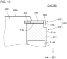
- Fig. 10 is a C-C cross-sectional view of Fig. 8 .
- the lower plate 212 and the upper case 220 illustrated in Fig. 9 are not illustrated.
- a pressure release valve 214f illustrated in Fig. 8 is not illustrated.
- an unillustrated battery module 100 is disposed in the storage space 250 in the cross-section illustrated in Figs. 9 and 10 .
- a white circle with a black dot indicating the Z direction indicates that an arrow indicating the Z direction extends from back to front of the surface of paper.
- a white circle with X indicating the X direction indicates that an arrow indicating the X direction extends from front to back of the surface of paper.
- the side frame 214 includes a lower attachment portion 214a, a partition wall 214b, and a projected portion 214c.
- the upper case 220 includes an upper attachment portion 220a, an upper cover portion 220b, and a side cover portion 220c.
- the lower attachment portion 214a and the upper attachment portion 220a are attached to each other via the sealing member 230.
- the lower attachment portion 214a is at least a part of the upper surface of the side frame 214.
- the upper attachment portion 220a is at least a part of the outer circumference portion of the upper case 220.
- the lower attachment portion 214a and the upper attachment portion 220a are fixed to each other by a plurality of fasteners 240.
- the plurality of fasteners 240 are disposed in a predetermined interval over the entire circumference of the sealing member 230.
- the number of fasteners 240 provided in the entire circumference of the sealing member 230 may be only one.
- each fastener 240 is fastened to the lower attachment portion 214a through the upper attachment portion 220a and the sealing member 230 substantially in parallel to the Z direction.
- the sealing member 230 is pressed substantially in parallel to the Z direction by fastening the lower attachment portion 214a and the upper attachment portion 220a to each other by the fastener 240. With this, the sealing of the sealing material 230 is improved.
- each fastener 240 is a bolt.
- an unillustrated nut through which a tip end of the fastener 240 extends is provided inside the side frame 214.
- each fastener 240 may be a fastener other than a bolt.
- the sealing member 230 is provided with a through-hole through which each fastener 240 extends.
- a structure in which the fastener 240 extends through the sealing member 230 is not limited to this example.
- a notch may be provided on at least one of the inner circumference edge and the outer circumference edge of the sealing member 230.
- each fastener 240 can extend through the sealing member 230 via the notch of the sealing member 230.
- gas may be generated from the battery module 100.
- a gas discharge path 214d is provided inside the side frame 214.
- the gas discharge path 214 is hollow.
- the inside surface of the side frame 214 is provided with a plurality of gas discharge holes 214e.
- the plurality of gas discharge holes 214e is disposed in a predetermined interval over the entire circumference of the side frame 214.
- the storage space 250 and the gas discharge path 214d communicate with each other via the plurality of gas discharge holes 214e.
- the pressure release valve 214f is provided on a part of the outside surface of the side frame 214. Accordingly, the gas generated from the battery module 100 in the storage space 250 can be discharged from the pressure release valve 214f through the gas discharge hole 214e and the gas discharge path 214d to the outside of the storage body 200.
- the upper cover portion 220b is surrounded by the upper attachment portion 220a.
- the upper cover portion 220a covers the storage space 250 from above.
- the partition wall 214b protrudes upward from the lower attachment portion 214a. As illustrated in Fig. 9 , the partition wall 214b is provided on the inside end portion of the lower attachment portion 214a. Thereby, the partition wall 214b is located between the battery module 100 and the sealing member 230. For this reason, the partition wall 214b can separate the battery module 100 and the sealing member 230 from each other. As illustrated in Fig. 8 , as viewed from the Z direction, the partition wall 214b continuously extends over the entire circumference of the side frame 214 except a plurality of grooves 214b1. However, the shape of the partition wall 214b viewed from the Z direction is not limited to this example.
- the partition wall 214b can function as at least a portion of a structure for inhibiting the high-temperature gas from being directly expelled to the sealing member 230.
- the side cover portion 220c is provided on the outer edge of the upper attachment portion 220a. As illustrated in Figs. 9 and 10 , the lower end of the side cover portion 220c protrudes downward from the outer edge of the upper attachment portion 220a.
- the side cover portion 220c covers a surface of the sealing member 230 on the opposite side of the storage space 250. Under a predetermined condition such as washing of an automobile mounted with the battery pack 10A, there is a possibility that high-pressure water is expelled from the outside of the storage body 200.
- the side cover portion 220c can function as at least a portion of a structure for inhibiting the water from being directly expelled to the sealing member 230.
- the projected portion 214c is located below the side cover portion 220c.
- the projected portion 214c projects outward more than the side cover portion 220c.
- the projected portion 214c continuously extends over the entire circumference of the side frame 214.
- the projected portion 214c may be partially lacked in the entire circumference of the side frame 214.
- the projected portion 214c can function as at least a portion of a structure for inhibiting the water from being directly expelled to the sealing member 230.
- the sealing member 230 is disposed along the partition wall 214b. In other words, the sealing member 230 is aligned by the partition wall 214b. This can restrict the sealing member 230 from being displaced to the storage space 250 side. For this reason, the sealing member 230 can be accurately positioned. Accordingly, sealing of the storage space 250 can be improved.
- a plurality of engagement portions 232 is provided on the side portion of the sealing member 230 on the storage space 250 side. As viewed from the Z direction, the plurality of engagement portions 232 is disposed in a predetermined interval over the entire circumference of the sealing member 230. However, the number of engagement portions 232 provided in the entire circumference of the sealing member 230 may be only one.
- the position where the engagement portion 232 is disposed is not limited to the position according to the embodiment 2.
- the engagement portion 232 may be provided, for example, on the side portion of the sealing member 230 opposite to the storage space 250. Alternatively, the engagement portion 232 may be provided on both of the side portion of the sealing member 230 on the storage space 250 side and the side portion of the sealing member 230 opposite to the storage space 250.
- each engagement portion 232 has a substantially T shape. Specifically, as viewed from the Z direction, each engagement portion 232 includes a protrusion 232a and a pair of engagement protrusions 232b. As viewed from the Z direction, the protrusion 232a protrudes from the side portion of the sealing member 230 on the storage space 250 side toward the storage space 250 side. As viewed from the Z direction, the pair of engagement protrusions 232b protrudes from both side portions of the tip end of the protrusion 232a toward sides opposite to each other.
- each of the plurality of protrusions 232a is disposed in each of a plurality of grooves 214b1 provided on the partition wall 214b.
- each protrusion 232a is an engagement structure for engaging the partition wall 214b and the sealing member 230 with each other. This can restrict the sealing member 230 from being circumferentially displaced about the storage space 250. For this reason, the sealing member 230 can be accurately positioned. Accordingly, the sealing of the storage space 250 can be improved.
- each of the pair of engagement protrusions 232b provided to each protrusion 232a can contact with the inner circumference surface of the partition wall 214b on the storage space 250 side.
- each engagement protrusion 232b is an engagement structure for engaging the partition wall 214b and the protrusion 232a with each other. This can restrict the sealing member 230 from being displaced to the outside of the storage space 250. For this reason, the sealing member 230 can be accurately positioned. Accordingly, the sealing of the storage space 250 can be improved.
- each engagement portion 232 is located laterally to the sealing member 230 with respect to the Z direction. For this reason, the sealing of the sealing member 230 can be less susceptible to the engagement portion 232 compared with when the engagement portion 232 is provided on the position overlapped with the sealing member 230 in the Z direction. Accordingly, the sealing of the storage space 250 can be improved.
- the shape of the engagement portion 232 is not limited to the example illustrated in Fig. 8 .
- each engagement protrusion 232b may enter, for example, a concave portion provided on the side surface of each groove 214b1. Also in this example, the engagement protrusion 232b can be an engagement structure for engaging the partition wall 214b and the protrusion 232a with each other.
- the engagement portion 232 may have, for example, a substantially L shape.
- the engagement protrusion 232b may protrude from only either of both side portions of each protrusion 232a.
- the engagement protrusion 232b can be an engagement structure for engaging the partition wall 214b and the protrusion 232a with each other.
- the engagement portion 232 may include only the protrusion 232a without the engagement protrusion 232b.
- the protrusion 232a can be an engagement structure for engaging the partition wall 214b and the sealing member 230 with each other.
- the engagement protrusion 232b protrudes from the protrusion 232a substantially in parallel to the horizontal direction.
- the engagement protrusion 232b may protrude upward or downward from the protrusion 232a.
- the engagement protrusion 232b may enter a hole provided on the bottom surface of the groove 214b1.
- the engagement protrusion 232b can be an engagement structure for engaging the side frame 214 and the protrusion 232a with each other.
- the battery pack 10B according to the embodiment 2 may include, for example, a configuration similar to the configuration described for the battery pack 10A according to the embodiment 1.
- at least a portion of the partition wall 214b may be located at a higher elevation than the upper surface of the battery module 100 similarly to the embodiment 1.
- 10A, 10B Battery pack 100 Battery module, 110 Terminal, 200 Storage body, 210 Lower case, 212 Lower plate, 214 Side frame, 214a Lower attachment portion, 214b Partition wall, 214b1 Groove, 214c Projected portion, 214d Gas discharge path, 214e Gas discharge hole, 214f Pressure release valve, 220 Upper case, 220a Upper attachment portion, 220b Upper cover portion, 220c Side cover portion, 230 Sealing member, 232 Engagement portion, 232a Protrusion, 232b Engagement protrusion, 240 Fastener, 250 Storage space, L Virtual line
Landscapes
- Chemical & Material Sciences (AREA)
- Chemical Kinetics & Catalysis (AREA)
- Electrochemistry (AREA)
- General Chemical & Material Sciences (AREA)
- Engineering & Computer Science (AREA)
- Aviation & Aerospace Engineering (AREA)
- Battery Mounting, Suspending (AREA)
Abstract
Description
- The present invention relates to a battery pack.
- In recent years, a battery pack used for various applications such as an automobile has been developed. The battery pack includes at least one battery module and a storage body storing the at least one module.
- Patent Document 1 describes one example of a battery pack. In this battery pack, a storage body incudes a battery tray and a battery cover. The battery tray and the battery cover are attached to each other via a sealing member.
- Patent Document 2 describes one example of a battery pack. In this battery pack, a storage body includes a main body portion and a lid portion. The main body portion and the lid portion are joined to each other in a joining portion. In the joining portion, the main body portion and the lid portion are welded to each other.
-
- Patent Document 1:
Japanese Patent Application Publication No. 2011-194982 - Patent Document 2:
Japanese Patent Application Publication No. 2021-111562 - For example, as described in Patent Document 1, a storage space of a storage body may be surrounded by a sealing member. This case may require improvement of sealing of the storage space of the storage body.
- One example of an object of the aspect 1 according to the present invention is to improve sealing of a storage space of a storage body. Another object of the aspect 1 according to the present invention may be apparent from description of the present specification.
- For example, as described in Patent Document 1, a storage space of a storage body may be surrounded by a sealing member. This case may require improvement of sealing of the storage space of the storage body. The sealing member is preferably positioned accurately to improve sealing of the storage space. It may be, however, difficult to accurately position the sealing member simply by disposing the sealing member.
- One example of an object of the aspect 2 according to the present invention is to improve sealing of a storage space of a storage body. Another object of the aspect 2 according to the present invention may be apparent from description of the present specification.
- The aspect 1 according to the present invention is as described below.
- [1.1] A battery pack including:
- a storage body provided with a storage space surrounded by a sealing member;
- a battery module stored in the storage space; and
- a partition wall located between the battery module and the sealing member, wherein
- at least a portion of the partition wall is located at a higher elevation than an upper surface of the battery module.
- [1.2] The battery pack according to [1.1], wherein
the at least a portion of the partition wall is located at a higher elevation than an upper surface of the sealing member. - [1.3] The battery pack according to [1.1] or [1.2], wherein
- the storage body is provided with a gas discharge hole to discharge gas generated from the storage space, and
- at least a portion of the partition wall is disposed above the gas discharge hole.
- [1.4] The battery pack according to any one of [1.1] to [1.3], wherein
the partition wall is a part of the storage body. - [1.5] A battery pack including:
- a storage body provided with a storage space surrounded by a sealing member;
- a battery module stored in the storage space; and
- a cover portion that covers a surface of the sealing member on an opposite side of the storage space, wherein
- at least a portion of the cover portion is located at a lower elevation than a lower surface of the sealing member.
- [1.6] The battery pack according to [1.5], wherein
the cover portion is a part of the storage body. - [1.7] The battery pack according to [1.5] or [1.6], further including
a projected portion provided below the cover portion and projecting outward more than the cover portion. - [1.8] The battery pack according to [1.7], wherein
the projected portion is a part of the storage body. - The aspect 2 according to the present invention is as described below.
- [2.1] A battery pack including:
- a storage body provided with a storage space surrounded by a sealing member pressed in a predetermined direction;
- a battery module stored in the storage space; and
- an engagement portion that engages the storage body and the sealing member with each other and is located laterally to the sealing member with respect to the predetermined direction.
- [2.2] The battery pack according to [2.1], wherein
the engagement portion includes a protrusion protruding from the sealing member, and an engagement structure that engages the storage body and the protrusion with each other. - [2.3] The battery pack according to [2.1] or [2.2], wherein
- the storage body includes a partition wall that separates the battery module and the sealing member from each other, and
- the engagement portion is engaged with the partition wall.
- [2.4] The battery pack according to any one of [2.1] to [2.3], further including
a fastener that fastens predetermined portions of the storage body to each other and extends through the sealing member. - According to the aspect 1 of the present invention, sealing of a storage space of a storage body is improved.
- According to the aspect 2 of the present invention, sealing of a storage space of a storage body is improved.
-
- [
Fig. 1 ] A perspective view of a battery pack according to the embodiment 1. - [
Fig. 2 ] A plan view of the battery pack according to the embodiment 1 with an upper case removed. - [
Fig. 3 ] An enlarged plan view of a part of a side frame according to the embodiment 1. - [
Fig. 4 ] An A-A cross-sectional view ofFig. 3 . - [
Fig. 5 ] An enlarged view of a part ofFig. 4 . - [
Fig. 6 ] A perspective view of the battery pack according to the embodiment 1. - [
Fig. 7 ] A plan view of the battery pack according to the embodiment 1 with an upper case removed. - [
Fig. 8 ] An enlarged plan view of a part of the side frame according to the embodiment 1. - [
Fig. 9 ] A B-B cross-sectional view ofFig. 8 . - [
Fig. 10 ] A C-C cross-sectional view ofFig. 8 . - Hereinafter, an embodiment 1 according to the present invention is described by using drawings. In all drawings, a similar component is assigned with a similar reference sign, and description thereof is omitted as appropriate.
-
Fig. 1 is a perspective view of abattery pack 10A according to the embodiment 1.Fig. 2 is a plan view of thebattery pack 10A according to the embodiment 1 with anupper case 220 removed. - In the embodiment 1, the
battery pack 10A is mounted on an automobile. Specifically, thebattery pack 10A is mounted between a front wheel and a rear wheel of the automobile. Hereinafter, unless otherwise specified, thebattery pack 10A is described as being mounted on an automobile. However, thebattery pack 10A is applicable to an application for other than an automobile. - In each drawing, for description, an X direction, a Y direction, and a Z direction are indicated. The X direction indicates a front-rear direction of the
battery pack 10A. The Y direction is orthogonal to the X direction. The Y direction indicates a left-right direction of thebattery pack 10A. The Z direction is orthogonal to both of the X direction and the Y direction. The Z direction indicates a vertical direction of thebattery pack 10A. An arrow indicating the X direction and arrows indicating the Y direction and indicating the Z direction indicate a front direction, a left direction, and an upper direction of thebattery pack 10A respectively. InFig. 2 , a white circle with a black dot indicating the Z direction indicates that an arrow indicating the Z direction extends from back to front of a surface of paper. However, a relation between the X direction, the Y direction, and the Z direction, and the front-rear direction, the left-right direction, and the vertical direction of thebattery pack 10A is not limited to this example. - In the embodiment 1, the front-rear direction, the left-right direction, and the vertical direction of the
battery pack 10A are determined by an automobile mounted with thebattery pack 10A. The X direction, the Y direction, and the Z direction indicate a front-rear direction, a left-right direction, and a vertical direction of the automobile respectively. The arrow indicating the X direction, the arrow indicating the Y direction, and the arrow indicating the Z direction indicate a front direction, a left direction, and an upper direction of the automobile respectively. However, the relation between the front-rear direction, the left-right direction, and the vertical direction of thebattery pack 10A, and the front-rear direction, the left-right direction, and the vertical direction of the automobile is not limited to this example. - Hereinafter, a direction perpendicular to the Z direction is referred to as a horizontal direction as necessary.
- The
battery pack 10A includes fourbattery modules 100 and astorage body 200. The fourbattery modules 100 include a pair ofbattery modules 100 on a left side arranged in the X direction and a pair ofbattery modules 100 on a right side arranged in the X direction. Thestorage body 200 includes alower case 210 and anupper case 220. Thelower case 210 may be generally referred to, for example, as a tray or a main body portion. Thelower case 210 includes alower plate 212 and aside frame 214. Theupper case 220 may be generally referred to, for example, as a cover or a lid portion. - Each
battery module 100 includes a plurality of battery cells stacked in the horizontal direction. In eachbattery module 100, for example, a plurality of battery cell groups each including a plurality of battery cells connected in parallel is connected in series. Alternatively, a plurality of single battery cells may be connected in series. - The front side of the
side frame 214 is provided with a pair ofterminals 110. The pair ofterminals 110 is arranged substantially parallel to the Y direction. The front end portion of each terminal 110 protrudes forward from the front surface of theside frame 214. In an electric path, the fourbattery modules 100 are connected in series between the pair ofterminals 110. - The
lower case 210 and theupper case 220 are attached to each other via a sealingmember 230. Thelower case 210, theupper case 220, and the sealingmember 230 form astorage space 250. The fourbattery modules 100 are stored in thestorage space 250. - The
lower plate 212 defines a bottom portion of thestorage space 250. Theside frame 214 defines a side portion of thestorage space 250. Specifically, as viewed from the Z direction, theside frame 214 is provided along the outermost circumference of thelower plate 212. Theupper case 220 defines a top portion of thestorage space 250. - The sealing
member 230 is, for example, an elastic material such as rubber. As viewed from the Z direction, the sealingmember 230 is provided over the entire circumference of theside frame 214. Thereby, as viewed from the Z direction, the sealingmember 230 surrounds thestorage space 250. Thestorage space 250 can be therefore sealed by the sealingmember 230 from the external space of thestorage body 200. - The number of and arrangement of the battery modules are not limited to the example according to the embodiment 1. The number of
battery modules 100 may be, for example, only two, only three, or five or more. -
Fig. 3 is an enlarged plan view of a part of theside frame 214 according to the embodiment 1.Fig. 4 is an A-A cross-sectional view ofFig. 3 .Fig. 5 is an enlarged view of a part ofFig. 4 . InFig. 3 , for simple description, thebattery module 100, thelower plate 212, and theupper case 220 illustrated inFig. 4 are not illustrated. InFig. 4 , for simple description, apressure release valve 214f illustrated inFig. 3 is not illustrated. InFig. 3 , a white circle with a black dot indicating the Z direction indicates that an arrow indicating the Z direction extends from back to front of the surface of paper. InFigs. 4 and5 , a white circle with X indicating the X direction indicates that an arrow indicating the X direction extends from front to back of the surface of paper. - As illustrated in
Fig. 4 , theside frame 214 includes alower attachment portion 214a, apartition wall 214b, and a projectedportion 214c. Theupper case 220 includes anupper attachment portion 220a, anupper cover portion 220b, and aside cover portion 220c. - With reference to
Figs. 3 and4 , an attachment structure of thelower case 210 and theupper case 220 is described. - As illustrated in
Fig. 4 , thelower attachment portion 214a and theupper attachment portion 220a are attached to each other via the sealingmember 230. Thelower attachment portion 214a is at least a part of the upper surface of theside frame 214. Theupper attachment portion 220a is at least a part of the outer circumference portion of theupper case 220. As illustrated inFig. 3 , thelower attachment portion 214a and theupper attachment portion 220a are fixed to each other by a plurality offasteners 240. The plurality offasteners 240 is disposed in a predetermined interval over the entire circumference of theside frame 214. As illustrated inFig. 4 , eachfastener 240 is fastened to thelower attachment portion 214a through theupper attachment portion 220a and the sealingmember 230 substantially in parallel to the Z direction. In the embodiment 1, eachfastener 240 is a bolt. However, eachfastener 240 may be a fastener other than a bolt. - With reference to
Figs. 3 and4 , a discharge structure of gas from thestorage space 250 is described. In thestorage space 250, gas may be generated from thebattery module 100. - As illustrated in
Fig. 4 , agas discharge path 214d is provided inside theside frame 214. Thegas discharge path 214d is hollow. As illustrated inFig. 3 , the inside surface of theside frame 214 is provided with a plurality ofgas discharge holes 214e. As viewed from the Z direction, the plurality ofgas discharge holes 214e is disposed in a predetermined interval over the entire circumference of theside frame 214. Thestorage space 250 and thegas discharge path 214d communicate with each other via the plurality ofgas discharge holes 214e. As illustrated inFig. 3 , thepressure release valve 214f is provided on a part of the outside surface of theside frame 214. Accordingly, the gas generated from thebattery module 100 in thestorage space 250 can be discharged from thepressure release valve 214f through thegas discharge hole 214e and thegas discharge path 214d to the outside of thestorage body 200. - With reference to
Figs. 3 and4 , the inside structure of thestorage body 200 in the Y direction with respect to the sealingmember 230 is described. - As viewed from the Z direction, the
upper cover portion 220b is surrounded by theupper attachment portion 220a. Theupper cover portion 220b covers thestorage space 250 from above. - The
partition wall 214b protrudes upward from thelower attachment portion 214a. As illustrated inFig. 4 , thepartition wall 214b is provided on the inside end portion of thelower attachment portion 214a. Thereby, thepartition wall 214b is located between thebattery module 100 and the sealingmember 230. For this reason, thepartition wall 214b can separate thebattery module 100 and the sealingmember 230 from each other. As illustrated inFig. 3 , as viewed from the Z direction, thepartition wall 214b continuously extends over the entire circumference of theside frame 214. However, thepartition wall 214b may be partially lacked in the entire circumference of theside frame 214. - As illustrated in
Fig. 4 , at least a portion of thepartition wall 214b is located at a higher elevation than the upper surface of thebattery module 100. In the example illustrated inFig. 4 , the upper surface of thepartition wall 214b is located at a higher elevation than the upper surface of thebattery module 100 by a height ΔH1. Under a predetermined condition such as charge/discharge of thebattery module 100, there is a possibility that high-temperature gas is generated from thebattery module 100. According to the embodiment 1, thepartition wall 214b can function as at least a portion of a structure for inhibiting the high-temperature gas from being directly expelled to the sealingmember 230. In the embodiment 1, accordingly, breakage of the sealingmember 230 caused by direct ejection of the high-temperature gas to the sealingmember 230 can be reduced. For this reason, the sealing of thestorage space 250 can be improved in the embodiment 1. - As illustrated in
Fig. 4 , at least a portion of thepartition wall 214b is located at a higher elevation than the upper surface of the sealingmember 230. In the example illustrated inFig. 4 , the upper surface of thepartition wall 214b is located at a higher elevation than the upper surface of the sealingmember 230 by a height Δh. Thereby, thepartition wall 214b can easily function as at least a portion of a structure for inhibiting the above-described high-temperature gas from being directly expelled to the sealingmember 230. The embodiment 1 can accordingly reduce breakage of the sealingmember 230 caused by direct expulsion of the high-temperature gas to the sealingmember 230. For this reason, the sealing of thestorage space 250 can be improved in the embodiment 1. - As illustrated in
Fig. 3 , at least a portion of thepartition wall 214b is disposed above eachgas discharge hole 214e. The above-described high-temperature gas is likely to be expelled toward thegas discharge hole 214e or toward an upper side of thegas discharge hole 214e. In the embodiment 1, however, thepartition wall 214b can inhibit the high-temperature gas from being directly expelled to the sealingmember 230 even if the high-temperature gas is expelled toward the upper side of thegas discharge hole 214e. - A partition wall located between the
battery module 100 and the sealingmember 230 is not limited to thepartition wall 214b according to the embodiment 1. In the embodiment 1, thepartition wall 214b is a part of thelower case 210. However, the partition wall may be a part of theupper case 220. Alternatively, the partition wall may be a member independent of thestorage body 200. - With reference to
Figs. 3 to 5 , a structure of an outside of thestorage body 200 in the Y direction with respect to the sealingmember 230 is described. - As viewed from the Z direction, the
side cover portion 220c is provided on an outer edge of theupper attachment portion 220a. As illustrated inFig. 4 , the lower end of theside cover portion 220c protrudes downward from the outer edge of theupper attachment portion 220a. Theside cover portion 220c covers a surface of the sealingmember 230 on the opposite side of thestorage space 250. In the example illustrated inFig. 4 , the lower end of theside cover portion 220c is located at a lower elevation than the upper end of thepartition wall 214b. The lower end of theside cover portion 220c is located on the outside of the outer edge of theupper attachment portion 220a. - As illustrated in
Fig. 5 , at least a portion of theside cover portion 220c is located at a lower elevation than the lower surface of the sealingmember 230. In the example illustrated inFig. 5 , the lower end of theside cover portion 220c is located at a lower elevation than the lower surface of the sealingmember 230 by a height ΔH2. Under a predetermined condition such as washing of an automobile mounted with thebattery pack 10A, there is a possibility that high-pressure water is expelled from obliquely below on the outside of thestorage body 200. In the embodiment 1, theside cover portion 220c can function as at least a portion of a structure for inhibiting the water from being directly expelled to the sealingmember 230. The embodiment 1 can accordingly reduce breakage of the sealingmember 230 caused by direct expulsion of the water to the sealingmember 230. For this reason, the sealing of thestorage space 250 can be improved in the embodiment 1. - As illustrated in
Fig. 5 , the projectedportion 214c is located below theside cover portion 220c. The projectedportion 214c projects outward more than theside cover portion 220c. As illustrated inFig. 3 , as viewed from the Z direction, the projectedportion 214c continuously extends over the entire circumference of theside frame 214. However, the projectedportion 214c may be partially lacked in the entire circumference of theside frame 214. As described above, under a predetermined condition, there is a possibility that high-pressure water is expelled from obliquely below on the outside of thestorage body 200. In the embodiment 1, the projectedportion 214c can function as at least a portion of a structure for inhibiting the water from being directly expelled to the sealingmember 230. - As illustrated in
Fig. 5 , the sealingmember 230 and the projectedportion 214c are separated from each other via at least a portion of theside cover portion 220c. Specifically, as illustrated inFig. 5 , a virtual line L between the outermost corner of the lower attachment portion 124a and the outermost corner of the projectedportion 214c intersects with theside cover portion 220c. Under a predetermined condition such as washing of an automobile mounted with thebattery pack 10A, there is a possibility that high-pressure water is expelled along the virtual line L from the outside of thestorage body 200. According to the embodiment 1, the projectedportion 214c and theside cover portion 220c can function as at least a portion of a structure for inhibiting the water from being directly expelled to the sealingmember 230. The embodiment 1 can accordingly reduce breakage of the sealingmember 230 caused by direct expulsion of the water to the sealingmember 230. For this reason, the sealing of thestorage space 250 can be improved in the embodiment 1. - A cover portion covering a surface of the sealing
member 230 on the opposite side of thestorage space 250 is not limited to theside cover portion 220c according to the embodiment 1. In the embodiment 1, theside cover portion 220c is a part of theupper case 220. However, the cover portion may be a part of thelower case 210. Alternatively, the cover portion may be a member independent of thestorage body 200. - A projected portion projecting outward more than the
side cover portion 220c is not limited to the projectedportion 214c according to the embodiment 1. In the embodiment 1, the projectedportion 214c is a part of thelower case 210. However, the projected portion may be a part of theupper case 220. Alternatively, the projected portion may be a member independent of thestorage body 200. - As described above, while with reference to the drawings, the embodiment 1 according to the present invention has been described, these are exemplification of the present invention and various configurations other than the above are employable.
- Hereinafter, an embodiment 2 according to the present invention is described by using drawings. In all drawings, a similar component is assigned with a similar reference sign, and description thereof is omitted as appropriate.
-
Fig. 6 is a perspective view of abattery pack 10B according to the embodiment 2.Fig. 7 is a plan view of thebattery pack 10B according to the embodiment 2 with anupper case 220 removed. - In the embodiment 2, the
battery pack 10B is mounted on an automobile. Specifically, thebattery pack 10B is mounted between a front wheel and a rear wheel of the automobile. Hereinafter, unless otherwise specified, thebattery pack 10B is described as being mounted on an automobile. However, thebattery pack 10B is applicable to an application for other than an automobile. - In each drawing, for description, an X direction, a Y direction, and a Z direction are indicated. The X direction indicates a front-rear direction of the
battery pack 10B. The Y direction is orthogonal to the X direction. The Y direction indicates a left-right direction of thebattery pack 10B. The Z direction is orthogonal to both of the X direction and the Y direction. The Z direction indicates a vertical direction of thebattery pack 10B. An arrow indicating the X direction and arrows indicating the Y direction and indicating the Z direction indicate a front direction, a left direction, and an upper direction of thebattery pack 10B respectively. InFig. 7 , a white circle with a black dot indicating the Z direction indicates that an arrow indicating the Z direction extends from back to front of a surface of paper. However, a relation between the X direction, the Y direction, and the Z direction, and the front-rear direction, the left-right direction, and the vertical direction of thebattery pack 10B is not limited to this example. - In the embodiment 2, the front-rear direction, the left-right direction, and the vertical direction of the
battery pack 10B are determined by an automobile mounted with thebattery pack 10B. The X direction, the Y direction, and the Z direction indicate a front-rear direction, a left-right direction, and a vertical direction of the automobile respectively. The arrow indicating the X direction, the arrow indicating the Y direction, and the arrow indicating the Z direction indicate a front direction, a left direction, and an upper direction of the automobile respectively. However, the relation between the front-rear direction, the left-right direction, and the vertical direction of thebattery pack 10B, and the front-rear direction, the left-right direction, and the vertical direction of the automobile is not limited to this example. - Hereinafter, a direction perpendicular to the Z direction is referred to as a horizontal direction as necessary.
- The
battery pack 10B includes fourbattery modules 100 and astorage body 200. The fourbattery modules 100 include a pair ofbattery modules 100 on a left side arranged in the X direction and a pair ofbattery modules 100 on a right side arranged in the X direction. Thestorage body 200 includes alower case 210 and anupper case 220. Thelower case 210 may be generally referred to, for example, as a tray or a main body portion. Thelower case 210 includes alower plate 212 and aside frame 214. Theupper case 220 may be generally referred to, for example, as a cover or a lid portion. - Each
battery module 100 includes a plurality of battery cells stacked in the horizontal direction. In eachbattery module 100, for example, a plurality of battery cell groups each including a plurality of battery cells connected in parallel is connected in series. Alternatively, a plurality of single battery cells may be connected in series. - The front side of the
side frame 214 is provided with a pair ofterminals 110. The pair ofterminals 110 is arranged substantially parallel to the Y direction. The front end portion of each terminal 110 protrudes forward from the front surface of theside frame 214. In an electric path, the fourbattery modules 100 are connected in series between the pair ofterminals 110. - The
lower case 210 and theupper case 220 are attached to each other via a sealingmember 230. Thelower case 210, theupper case 220, and the sealingmember 230 form astorage space 250. The fourbattery modules 100 are stored in thestorage space 250. - The
lower plate 212 defines a bottom portion of thestorage space 250. Theside frame 214 defines a side portion of thestorage space 250. Specifically, as viewed from the Z direction, theside frame 214 is provided along the outermost circumference of thelower plate 212. Theupper case 220 defines a top portion of thestorage space 250. - The sealing
member 230 is, for example, an elastic material such as rubber. As viewed from the Z direction, the sealingmember 230 is provided over the entire circumference of theside frame 214. Thereby, as viewed from the Z direction, the sealingmember 230 surrounds thestorage space 250. Thestorage space 250 can be therefore sealed by the sealingmember 230 from the external space of thestorage body 200. - The number of and arrangement of the battery modules are not limited to the example according to the embodiment 2. The number of
battery modules 100 may be, for example, only two, only three, or five or more. -
Fig. 8 is an enlarged plan view of a part of theside frame 214 according to the embodiment 2.Fig. 9 is a B-B cross-sectional view ofFig. 8 .Fig. 10 is a C-C cross-sectional view ofFig. 8 . InFig. 8 , for simple description, thelower plate 212 and theupper case 220 illustrated inFig. 9 are not illustrated. InFigs. 9 and10 , for simple description, apressure release valve 214f illustrated inFig. 8 is not illustrated. In thestorage space 250 in the cross-section illustrated inFigs. 9 and10 , anunillustrated battery module 100 is disposed. InFig. 8 , a white circle with a black dot indicating the Z direction indicates that an arrow indicating the Z direction extends from back to front of the surface of paper. InFigs. 9 and10 , a white circle with X indicating the X direction indicates that an arrow indicating the X direction extends from front to back of the surface of paper. - As illustrated in
Fig. 9 , theside frame 214 includes alower attachment portion 214a, apartition wall 214b, and a projectedportion 214c. Theupper case 220 includes anupper attachment portion 220a, anupper cover portion 220b, and aside cover portion 220c. - With reference to
Figs. 8 and9 , an attachment structure of thelower case 210 and theupper case 220 is described. - As illustrated in
Fig. 9 , thelower attachment portion 214a and theupper attachment portion 220a are attached to each other via the sealingmember 230. Thelower attachment portion 214a is at least a part of the upper surface of theside frame 214. Theupper attachment portion 220a is at least a part of the outer circumference portion of theupper case 220. As illustrated inFig. 8 , thelower attachment portion 214a and theupper attachment portion 220a are fixed to each other by a plurality offasteners 240. As viewed from the Z direction, the plurality offasteners 240 are disposed in a predetermined interval over the entire circumference of the sealingmember 230. However, the number offasteners 240 provided in the entire circumference of the sealingmember 230 may be only one. As illustrated inFig. 9 , eachfastener 240 is fastened to thelower attachment portion 214a through theupper attachment portion 220a and the sealingmember 230 substantially in parallel to the Z direction. The sealingmember 230 is pressed substantially in parallel to the Z direction by fastening thelower attachment portion 214a and theupper attachment portion 220a to each other by thefastener 240. With this, the sealing of the sealingmaterial 230 is improved. In the embodiment 2, eachfastener 240 is a bolt. In one example, an unillustrated nut through which a tip end of thefastener 240 extends is provided inside theside frame 214. However, eachfastener 240 may be a fastener other than a bolt. - In the embodiment 2, the sealing
member 230 is provided with a through-hole through which eachfastener 240 extends. However, a structure in which thefastener 240 extends through the sealingmember 230 is not limited to this example. For example, as viewed from the Z direction, a notch may be provided on at least one of the inner circumference edge and the outer circumference edge of the sealingmember 230. In this example, eachfastener 240 can extend through the sealingmember 230 via the notch of the sealingmember 230. - With reference to
Figs. 8 and9 , a discharge structure of gas from thestorage space 250 is described. In thestorage space 250, gas may be generated from thebattery module 100. - As illustrated in
Figs. 9 and10 , agas discharge path 214d is provided inside theside frame 214. Thegas discharge path 214 is hollow. As illustrated inFig. 8 , the inside surface of theside frame 214 is provided with a plurality ofgas discharge holes 214e. As viewed from the Z direction, the plurality ofgas discharge holes 214e is disposed in a predetermined interval over the entire circumference of theside frame 214. Thestorage space 250 and thegas discharge path 214d communicate with each other via the plurality ofgas discharge holes 214e. As illustrated inFig. 8 , thepressure release valve 214f is provided on a part of the outside surface of theside frame 214. Accordingly, the gas generated from thebattery module 100 in thestorage space 250 can be discharged from thepressure release valve 214f through thegas discharge hole 214e and thegas discharge path 214d to the outside of thestorage body 200. - With reference to
Figs. 8 and9 , the inside structure of thestorage body 200 in the Y direction with respect to the sealingmember 230 is described. - As viewed from the Z direction, the
upper cover portion 220b is surrounded by theupper attachment portion 220a. Theupper cover portion 220a covers thestorage space 250 from above. - The
partition wall 214b protrudes upward from thelower attachment portion 214a. As illustrated inFig. 9 , thepartition wall 214b is provided on the inside end portion of thelower attachment portion 214a. Thereby, thepartition wall 214b is located between thebattery module 100 and the sealingmember 230. For this reason, thepartition wall 214b can separate thebattery module 100 and the sealingmember 230 from each other. As illustrated inFig. 8 , as viewed from the Z direction, thepartition wall 214b continuously extends over the entire circumference of theside frame 214 except a plurality of grooves 214b1. However, the shape of thepartition wall 214b viewed from the Z direction is not limited to this example. Under a predetermined condition such as charge/discharge of thebattery module 100, there is a possibility that high-temperature gas is generated from thebattery module 100. Thepartition wall 214b can function as at least a portion of a structure for inhibiting the high-temperature gas from being directly expelled to the sealingmember 230. - With reference to
Figs. 8 and9 , a structure of an outside of thestorage body 200 in the Y direction with respect to the sealingmember 230 is described. - As viewed from the Z direction, the
side cover portion 220c is provided on the outer edge of theupper attachment portion 220a. As illustrated inFigs. 9 and10 , the lower end of theside cover portion 220c protrudes downward from the outer edge of theupper attachment portion 220a. Theside cover portion 220c covers a surface of the sealingmember 230 on the opposite side of thestorage space 250. Under a predetermined condition such as washing of an automobile mounted with thebattery pack 10A, there is a possibility that high-pressure water is expelled from the outside of thestorage body 200. Theside cover portion 220c can function as at least a portion of a structure for inhibiting the water from being directly expelled to the sealingmember 230. - As illustrated in
Fig. 10 , the projectedportion 214c is located below theside cover portion 220c. The projectedportion 214c projects outward more than theside cover portion 220c. As illustrated inFig. 8 , as viewed from the Z direction, the projectedportion 214c continuously extends over the entire circumference of theside frame 214. However, the projectedportion 214c may be partially lacked in the entire circumference of theside frame 214. Under a predetermined condition such as washing of an automobile mounted with thebattery pack 10B, there is a possibility that high-pressure water is expelled from obliquely below on the outside of thestorage body 200. The projectedportion 214c can function as at least a portion of a structure for inhibiting the water from being directly expelled to the sealingmember 230. - With reference to
Figs. 8 to 10 , the sealingmember 230 is described. - As illustrated in
Fig. 8 , as viewed from the Z direction, the sealingmember 230 is disposed along thepartition wall 214b. In other words, the sealingmember 230 is aligned by thepartition wall 214b. This can restrict the sealingmember 230 from being displaced to thestorage space 250 side. For this reason, the sealingmember 230 can be accurately positioned. Accordingly, sealing of thestorage space 250 can be improved. - As illustrated in
Fig. 8 , a plurality ofengagement portions 232 is provided on the side portion of the sealingmember 230 on thestorage space 250 side. As viewed from the Z direction, the plurality ofengagement portions 232 is disposed in a predetermined interval over the entire circumference of the sealingmember 230. However, the number ofengagement portions 232 provided in the entire circumference of the sealingmember 230 may be only one. The position where theengagement portion 232 is disposed is not limited to the position according to the embodiment 2. Theengagement portion 232 may be provided, for example, on the side portion of the sealingmember 230 opposite to thestorage space 250. Alternatively, theengagement portion 232 may be provided on both of the side portion of the sealingmember 230 on thestorage space 250 side and the side portion of the sealingmember 230 opposite to thestorage space 250. - As illustrated in
Fig. 8 , as viewed from the Z direction, eachengagement portion 232 has a substantially T shape. Specifically, as viewed from the Z direction, eachengagement portion 232 includes aprotrusion 232a and a pair ofengagement protrusions 232b. As viewed from the Z direction, theprotrusion 232a protrudes from the side portion of the sealingmember 230 on thestorage space 250 side toward thestorage space 250 side. As viewed from the Z direction, the pair ofengagement protrusions 232b protrudes from both side portions of the tip end of theprotrusion 232a toward sides opposite to each other. - As illustrated in
Fig. 8 , each of the plurality ofprotrusions 232a is disposed in each of a plurality of grooves 214b1 provided on thepartition wall 214b. In other words, eachprotrusion 232a is an engagement structure for engaging thepartition wall 214b and the sealingmember 230 with each other. This can restrict the sealingmember 230 from being circumferentially displaced about thestorage space 250. For this reason, the sealingmember 230 can be accurately positioned. Accordingly, the sealing of thestorage space 250 can be improved. - As illustrated in
Fig. 8 , each of the pair ofengagement protrusions 232b provided to eachprotrusion 232a can contact with the inner circumference surface of thepartition wall 214b on thestorage space 250 side. In other words, eachengagement protrusion 232b is an engagement structure for engaging thepartition wall 214b and theprotrusion 232a with each other. This can restrict the sealingmember 230 from being displaced to the outside of thestorage space 250. For this reason, the sealingmember 230 can be accurately positioned. Accordingly, the sealing of thestorage space 250 can be improved. - In the embodiment 2, each
engagement portion 232 is located laterally to the sealingmember 230 with respect to the Z direction. For this reason, the sealing of the sealingmember 230 can be less susceptible to theengagement portion 232 compared with when theengagement portion 232 is provided on the position overlapped with the sealingmember 230 in the Z direction. Accordingly, the sealing of thestorage space 250 can be improved. - The shape of the
engagement portion 232 is not limited to the example illustrated inFig. 8 . - As viewed from the Z direction, each
engagement protrusion 232b may enter, for example, a concave portion provided on the side surface of each groove 214b1. Also in this example, theengagement protrusion 232b can be an engagement structure for engaging thepartition wall 214b and theprotrusion 232a with each other. - As viewed from the Z direction, the
engagement portion 232 may have, for example, a substantially L shape. In other words, as viewed from the Z direction, theengagement protrusion 232b may protrude from only either of both side portions of eachprotrusion 232a. Also in this example, theengagement protrusion 232b can be an engagement structure for engaging thepartition wall 214b and theprotrusion 232a with each other. - As viewed from the Z direction, the
engagement portion 232 may include only theprotrusion 232a without theengagement protrusion 232b. Also, in this example, theprotrusion 232a can be an engagement structure for engaging thepartition wall 214b and the sealingmember 230 with each other. - In the embodiment 2, the
engagement protrusion 232b protrudes from theprotrusion 232a substantially in parallel to the horizontal direction. However, theengagement protrusion 232b may protrude upward or downward from theprotrusion 232a. For example, theengagement protrusion 232b may enter a hole provided on the bottom surface of the groove 214b1. Also in this example, theengagement protrusion 232b can be an engagement structure for engaging theside frame 214 and theprotrusion 232a with each other. - As described above, while with reference to the drawings, the embodiment 2 according to the present invention has been described, these are exemplification of the present invention and various configurations other than the above are employable.
- The
battery pack 10B according to the embodiment 2 may include, for example, a configuration similar to the configuration described for thebattery pack 10A according to the embodiment 1. For example, in the embodiment 2, at least a portion of thepartition wall 214b may be located at a higher elevation than the upper surface of thebattery module 100 similarly to the embodiment 1. - This application claims priorities based on
Japanese patent application No. 2022-127754 filed on August 10, 2022 Japanese patent application No. 2022-127755 filed on August 10, 2022 - 10A, 10B Battery pack, 100 Battery module, 110 Terminal, 200 Storage body, 210 Lower case, 212 Lower plate, 214 Side frame, 214a Lower attachment portion, 214b Partition wall, 214b1 Groove, 214c Projected portion, 214d Gas discharge path, 214e Gas discharge hole, 214f Pressure release valve, 220 Upper case, 220a Upper attachment portion, 220b Upper cover portion, 220c Side cover portion, 230 Sealing member, 232 Engagement portion, 232a Protrusion, 232b Engagement protrusion, 240 Fastener, 250 Storage space, L Virtual line
Claims (11)
- A battery pack comprising:a storage body provided with a storage space surrounded by a sealing member;a battery module stored in the storage space; anda partition wall located between the battery module and the sealing member, whereinat least a portion of the partition wall is located at a higher elevation than an upper surface of the battery module.
- The battery pack according to claim 1, wherein
the at least a portion of the partition wall is located at a higher elevation than an upper surface of the sealing member. - The battery pack according to claim 1 or 2, whereinthe storage body is provided with a gas discharge hole to discharge gas generated from the storage space, andat least a portion of the partition wall is disposed above the gas discharge hole.
- The battery pack according to claim 1 or 2, wherein
the partition wall is a part of the storage body. - A battery pack comprising:a storage body provided with a storage space surrounded by a sealing member;a battery module stored in the storage space; anda cover portion that covers a surface of the sealing member on an opposite side of the storage space, whereinat least a portion of the cover portion is located at a lower elevation than a lower surface of the sealing member.
- The battery pack according to claim 5, wherein
the cover portion is a part of the storage body. - The battery pack according to claim 5 or 6, further comprising
a projected portion provided below the cover portion and projecting outward more than the cover portion. - The battery pack according to claim 7, wherein
the projected portion is a part of the storage body. - The battery pack according to claim 1, further comprising
an engagement portion that engages the partition wall and the sealing member with each other. - The battery pack according to claim 9, wherein
the engagement portion includes a protrusion protruding from the sealing member, and an engagement structure that engages the storage body and the protrusion with each other. - The battery pack according to claim 9 or 10, further comprising
a fastener that fastens predetermined portions of the storage body to each other and extends through the sealing member.
Applications Claiming Priority (3)
| Application Number | Priority Date | Filing Date | Title |
|---|---|---|---|
| JP2022127754A JP2024024830A (en) | 2022-08-10 | 2022-08-10 | battery pack |
| JP2022127755A JP2024024831A (en) | 2022-08-10 | 2022-08-10 | battery pack |
| PCT/JP2023/028268 WO2024034490A1 (en) | 2022-08-10 | 2023-08-02 | Battery pack |
Publications (2)
| Publication Number | Publication Date |
|---|---|
| EP4571966A1 true EP4571966A1 (en) | 2025-06-18 |
| EP4571966A4 EP4571966A4 (en) | 2025-10-01 |
Family
ID=89851588
Family Applications (1)
| Application Number | Title | Priority Date | Filing Date |
|---|---|---|---|
| EP23852457.3A Pending EP4571966A4 (en) | 2022-08-10 | 2023-08-02 | BATTERY PACK |
Country Status (4)
| Country | Link |
|---|---|
| US (1) | US20260081290A1 (en) |
| EP (1) | EP4571966A4 (en) |
| CN (1) | CN119731849A (en) |
| WO (1) | WO2024034490A1 (en) |
Family Cites Families (14)
| Publication number | Priority date | Publication date | Assignee | Title |
|---|---|---|---|---|
| JP2011194982A (en) | 2010-03-18 | 2011-10-06 | Mitsubishi Motors Corp | Battery case for vehicle |
| KR101191659B1 (en) * | 2010-11-05 | 2012-10-17 | 에스비리모티브 주식회사 | Battery module |
| JP6065692B2 (en) * | 2013-03-25 | 2017-01-25 | 三菱自動車工業株式会社 | Battery pack |
| JP6020298B2 (en) * | 2013-03-29 | 2016-11-02 | 株式会社デンソー | Battery pack |
| JP5786974B2 (en) * | 2014-01-15 | 2015-09-30 | 三菱自動車工業株式会社 | Battery case |
| JP6299018B2 (en) * | 2014-06-09 | 2018-03-28 | 三菱自動車工業株式会社 | Battery pack |
| KR101725908B1 (en) * | 2014-11-17 | 2017-04-11 | 주식회사 엘지화학 | Battery Pack Having Portion for Fixing of Gasket |
| DE102019210790B4 (en) * | 2019-07-22 | 2023-11-02 | Volkswagen Aktiengesellschaft | Battery housing for a vehicle battery |
| JP7459516B2 (en) * | 2020-01-14 | 2024-04-02 | 株式会社Gsユアサ | Power storage device |
| CN115298889A (en) * | 2020-03-23 | 2022-11-04 | 松下知识产权经营株式会社 | Power storage module |
| KR102949549B1 (en) * | 2020-10-13 | 2026-04-06 | 주식회사 엘지에너지솔루션 | Battery pack and vehicle comprising the battery pack |
| JP7064077B1 (en) | 2021-02-22 | 2022-05-10 | 三菱重工業株式会社 | A method for manufacturing a sealing material for an electrochemical reaction cell, an electrochemical reaction cell cartridge, and a sealing material for an electrochemical reaction cell. |
| JP2022127755A (en) | 2021-02-22 | 2022-09-01 | スタンレー電気株式会社 | Vehicular lighting fixture and lens body |
| JP2024021615A (en) * | 2022-08-04 | 2024-02-16 | 株式会社Aescジャパン | battery pack |
-
2023
- 2023-08-02 WO PCT/JP2023/028268 patent/WO2024034490A1/en not_active Ceased
- 2023-08-02 EP EP23852457.3A patent/EP4571966A4/en active Pending
- 2023-08-02 CN CN202380057126.XA patent/CN119731849A/en active Pending
- 2023-08-02 US US19/102,396 patent/US20260081290A1/en active Pending
Also Published As
| Publication number | Publication date |
|---|---|
| US20260081290A1 (en) | 2026-03-19 |
| EP4571966A4 (en) | 2025-10-01 |
| CN119731849A (en) | 2025-03-28 |
| WO2024034490A1 (en) | 2024-02-15 |
Similar Documents
| Publication | Publication Date | Title |
|---|---|---|
| KR102065106B1 (en) | Secondary Battery Pack | |
| US12148948B2 (en) | Battery pack | |
| EP4407770B1 (en) | Battery pack | |
| JP2020191156A5 (en) | ||
| KR20220055978A (en) | Cap assembly and secondary battery including the same | |
| EP4468480A2 (en) | Battery module and battery pack | |
| US20250141035A1 (en) | Battery pack | |
| US20260081290A1 (en) | Battery pack | |
| US10847764B2 (en) | Battery pack including tray stopper for preventing spring back of pack cover | |
| EP4567981A1 (en) | Battery pack | |
| KR102924013B1 (en) | Battery Pack Case With Improved Impact Resistance and Battery Pack Including It | |
| JP6651882B2 (en) | Lead storage battery | |
| JP2024024831A (en) | battery pack | |
| KR20210041952A (en) | Battery Module | |
| US11830971B2 (en) | Battery cell, and battery module and battery pack including same | |
| JP2024024830A (en) | battery pack | |
| KR20230167525A (en) | Easy to assemble battery module | |
| CN210668456U (en) | Lithium polymer battery packaging structure and battery pack | |
| KR102871259B1 (en) | Battery Pack Having Improved Impact Strength | |
| EP4583292A1 (en) | Battery pack | |
| JP7756139B2 (en) | Battery pack | |
| CN218769845U (en) | New forms of energy battery box fixed subassembly | |
| KR20260033720A (en) | Battery module and battery pack and vehicle including the same | |
| JP7757376B2 (en) | Battery pack vehicle structure | |
| EP4700958A1 (en) | Battery pack and vehicle including same |
Legal Events
| Date | Code | Title | Description |
|---|---|---|---|
| STAA | Information on the status of an ep patent application or granted ep patent |
Free format text: STATUS: THE INTERNATIONAL PUBLICATION HAS BEEN MADE |
|
| PUAI | Public reference made under article 153(3) epc to a published international application that has entered the european phase |
Free format text: ORIGINAL CODE: 0009012 |
|
| STAA | Information on the status of an ep patent application or granted ep patent |
Free format text: STATUS: REQUEST FOR EXAMINATION WAS MADE |
|
| 17P | Request for examination filed |
Effective date: 20250210 |
|
| AK | Designated contracting states |
Kind code of ref document: A1 Designated state(s): AL AT BE BG CH CY CZ DE DK EE ES FI FR GB GR HR HU IE IS IT LI LT LU LV MC ME MK MT NL NO PL PT RO RS SE SI SK SM TR |
|
| REG | Reference to a national code |
Ref country code: DE Ref legal event code: R079 Free format text: PREVIOUS MAIN CLASS: H01M0050204000 Ipc: H01M0050271000 |
|
| A4 | Supplementary search report drawn up and despatched |
Effective date: 20250902 |
|
| RIC1 | Information provided on ipc code assigned before grant |
Ipc: H01M 50/271 20210101AFI20250827BHEP Ipc: H01M 50/244 20210101ALI20250827BHEP Ipc: H01M 50/262 20210101ALI20250827BHEP Ipc: H01M 50/291 20210101ALI20250827BHEP Ipc: H01M 50/367 20210101ALI20250827BHEP Ipc: H01M 50/249 20210101ALN20250827BHEP |
|
| DAV | Request for validation of the european patent (deleted) | ||
| DAX | Request for extension of the european patent (deleted) |