EP4571964A1 - Battery, and battery pack and vehicle comprising battery - Google Patents
Battery, and battery pack and vehicle comprising battery Download PDFInfo
- Publication number
- EP4571964A1 EP4571964A1 EP23904006.6A EP23904006A EP4571964A1 EP 4571964 A1 EP4571964 A1 EP 4571964A1 EP 23904006 A EP23904006 A EP 23904006A EP 4571964 A1 EP4571964 A1 EP 4571964A1
- Authority
- EP
- European Patent Office
- Prior art keywords
- battery
- cap
- gasket
- protrusion
- battery housing
- Prior art date
- Legal status (The legal status is an assumption and is not a legal conclusion. Google has not performed a legal analysis and makes no representation as to the accuracy of the status listed.)
- Pending
Links
Images


Classifications
-
- H—ELECTRICITY
- H01—ELECTRIC ELEMENTS
- H01M—PROCESSES OR MEANS, e.g. BATTERIES, FOR THE DIRECT CONVERSION OF CHEMICAL ENERGY INTO ELECTRICAL ENERGY
- H01M50/00—Constructional details or processes of manufacture of the non-active parts of electrochemical cells other than fuel cells, e.g. hybrid cells
- H01M50/10—Primary casings; Jackets or wrappings
- H01M50/183—Sealing members
- H01M50/184—Sealing members characterised by their shape or structure
-
- H—ELECTRICITY
- H01—ELECTRIC ELEMENTS
- H01M—PROCESSES OR MEANS, e.g. BATTERIES, FOR THE DIRECT CONVERSION OF CHEMICAL ENERGY INTO ELECTRICAL ENERGY
- H01M50/00—Constructional details or processes of manufacture of the non-active parts of electrochemical cells other than fuel cells, e.g. hybrid cells
- H01M50/10—Primary casings; Jackets or wrappings
- H01M50/102—Primary casings; Jackets or wrappings characterised by their shape or physical structure
- H01M50/107—Primary casings; Jackets or wrappings characterised by their shape or physical structure having curved cross-section, e.g. round or elliptic
-
- H—ELECTRICITY
- H01—ELECTRIC ELEMENTS
- H01M—PROCESSES OR MEANS, e.g. BATTERIES, FOR THE DIRECT CONVERSION OF CHEMICAL ENERGY INTO ELECTRICAL ENERGY
- H01M50/00—Constructional details or processes of manufacture of the non-active parts of electrochemical cells other than fuel cells, e.g. hybrid cells
- H01M50/10—Primary casings; Jackets or wrappings
- H01M50/147—Lids or covers
- H01M50/148—Lids or covers characterised by their shape
- H01M50/152—Lids or covers characterised by their shape for cells having curved cross-section, e.g. round or elliptic
-
- H—ELECTRICITY
- H01—ELECTRIC ELEMENTS
- H01M—PROCESSES OR MEANS, e.g. BATTERIES, FOR THE DIRECT CONVERSION OF CHEMICAL ENERGY INTO ELECTRICAL ENERGY
- H01M50/00—Constructional details or processes of manufacture of the non-active parts of electrochemical cells other than fuel cells, e.g. hybrid cells
- H01M50/10—Primary casings; Jackets or wrappings
- H01M50/147—Lids or covers
- H01M50/166—Lids or covers characterised by the methods of assembling casings with lids
- H01M50/167—Lids or covers characterised by the methods of assembling casings with lids by crimping
-
- H—ELECTRICITY
- H01—ELECTRIC ELEMENTS
- H01M—PROCESSES OR MEANS, e.g. BATTERIES, FOR THE DIRECT CONVERSION OF CHEMICAL ENERGY INTO ELECTRICAL ENERGY
- H01M50/00—Constructional details or processes of manufacture of the non-active parts of electrochemical cells other than fuel cells, e.g. hybrid cells
- H01M50/10—Primary casings; Jackets or wrappings
- H01M50/183—Sealing members
- H01M50/186—Sealing members characterised by the disposition of the sealing members
-
- H—ELECTRICITY
- H01—ELECTRIC ELEMENTS
- H01M—PROCESSES OR MEANS, e.g. BATTERIES, FOR THE DIRECT CONVERSION OF CHEMICAL ENERGY INTO ELECTRICAL ENERGY
- H01M50/00—Constructional details or processes of manufacture of the non-active parts of electrochemical cells other than fuel cells, e.g. hybrid cells
- H01M50/20—Mountings; Secondary casings or frames; Racks, modules or packs; Suspension devices; Shock absorbers; Transport or carrying devices; Holders
- H01M50/249—Mountings; Secondary casings or frames; Racks, modules or packs; Suspension devices; Shock absorbers; Transport or carrying devices; Holders specially adapted for aircraft or vehicles, e.g. cars or trains
-
- H—ELECTRICITY
- H01—ELECTRIC ELEMENTS
- H01M—PROCESSES OR MEANS, e.g. BATTERIES, FOR THE DIRECT CONVERSION OF CHEMICAL ENERGY INTO ELECTRICAL ENERGY
- H01M50/00—Constructional details or processes of manufacture of the non-active parts of electrochemical cells other than fuel cells, e.g. hybrid cells
- H01M50/30—Arrangements for facilitating escape of gases
- H01M50/342—Non-re-sealable arrangements
- H01M50/3425—Non-re-sealable arrangements in the form of rupturable membranes or weakened parts, e.g. pierced with the aid of a sharp member
-
- H—ELECTRICITY
- H01—ELECTRIC ELEMENTS
- H01M—PROCESSES OR MEANS, e.g. BATTERIES, FOR THE DIRECT CONVERSION OF CHEMICAL ENERGY INTO ELECTRICAL ENERGY
- H01M2220/00—Batteries for particular applications
- H01M2220/20—Batteries in motive systems, e.g. vehicle, ship, plane
-
- Y—GENERAL TAGGING OF NEW TECHNOLOGICAL DEVELOPMENTS; GENERAL TAGGING OF CROSS-SECTIONAL TECHNOLOGIES SPANNING OVER SEVERAL SECTIONS OF THE IPC; TECHNICAL SUBJECTS COVERED BY FORMER USPC CROSS-REFERENCE ART COLLECTIONS [XRACs] AND DIGESTS
- Y02—TECHNOLOGIES OR APPLICATIONS FOR MITIGATION OR ADAPTATION AGAINST CLIMATE CHANGE
- Y02E—REDUCTION OF GREENHOUSE GAS [GHG] EMISSIONS, RELATED TO ENERGY GENERATION, TRANSMISSION OR DISTRIBUTION
- Y02E60/00—Enabling technologies; Technologies with a potential or indirect contribution to GHG emissions mitigation
- Y02E60/10—Energy storage using batteries
Definitions
- the present disclosure relates to a battery, and a battery pack and a vehicle including the same.
- Batteries have high applicability according to product groups and electrical characteristics such as high energy density, and thus are commonly applied not only to portable devices but also to electric vehicles (EVs), hybrid electric vehicles (HEVs), and the like driven by electric power sources.
- EVs electric vehicles
- HEVs hybrid electric vehicles
- Such batteries are attracting attention as a new energy source to improve eco-friendliness and energy efficiency in that it has not only a primary advantage of dramatically reducing the use of fossil fuels, but also no by-products generated from the use of energy.
- Batteries widely used at present include lithium-ion batteries, lithium polymer batteries, nickel cadmium batteries, nickel hydrogen batteries, nickel zinc batteries, and the like.
- An operating voltage of such a unit battery cell is about 2.5 V to 4.5 V. Therefore, if a higher output voltage is required, a plurality of batteries may be connected in series to configure a battery pack. In addition, depending on the charge/discharge capacity required for the battery pack, a plurality of batteries may be connected in parallel to configure a battery pack.
- the number of batteries included in the battery pack and the type of electrical connection may be variously set according to the required output voltage and/or the demanded charge/discharge capacity.
- the internal pressure of the battery may increase, and a thermal event may spread as high-temperature gas and/or flames are generated therein.
- a thermal event occurs in a battery having high capacity and/or high power, it may cause even greater damage.
- a venting portion may be applied to the battery to release internal gas when the internal pressure increases above a certain level.
- a sealing portion for sealing the battery when a sealing portion for sealing the battery is not designed robustly, it may not operate smoothly at predictable times.
- the sealing portion for sealing the battery when the sealing portion for sealing the battery is not designed robustly, it may be impossible to guide venting in a desired direction through the venting portion.
- the sealing portion for sealing the battery when the sealing portion for sealing the battery is not designed robustly, there may be a problem that a leak may occur in the sealing portion due to changes in internal pressure even under normal use of the battery, thereby causing leakage of electrolytes.
- the present disclosure is designed to solve the problems of the related art, and therefore the present disclosure is directed to providing a battery configured to prevent the sealing portion of the battery from being broken when an abnormality occurs in the course of using the battery and thus the internal pressure increases abnormally or when the internal pressure increases under normal use.
- a battery according to an embodiment of the present disclosure for solving the above-described problem may include an electrode assembly; a battery housing configured to accommodate the electrode assembly through an opening formed on one side; a cap configured to cover the opening of the battery housing; and a gasket interposed between the cap and the inner surface of the battery housing and at least partially compressed, and having a protrusion on a surface facing the cap that protrudes in a direction toward the cap based on a state before being compressed.
- the protrusion may be provided in plurality, and the plurality of protrusions may be provided along a direction parallel to the direction from the outer side of the battery housing toward the inner side thereof.
- the gasket may have a flat shape with no protrusions appearing on the surface facing the cap while being compressed between the cap and the inner surface of the battery housing.
- An empty space may be formed between adjacent protrusions while the gasket is compressed between the cap and the inner surface of the battery housing.
- the gasket may be configured to have different compression rates in an area where the protrusion is provided and in an area where the protrusion is not provided.
- the battery housing may have a shape bent to surround an edge peripheral area of the cap on the opening side.
- the gasket may be configured to be bent into a shape corresponding to the bent shape of the battery housing to surround an edge peripheral area of the cap.
- the protrusion may be provided in at least one of an area facing the inner surface of the cap and an area facing the outer surface of the cap in the gasket.
- the cap may have a venting portion configured to be weaker compared to the rest of the cap.
- the cap may be configured not to be electrically connected to the electrode assembly.
- the cap may have an insertion portion inserted into an empty space formed between a pair of adjacent protrusions.
- the gasket may have a sub-protrusion that protrudes toward the inner surface of the battery housing based on a state before being compressed.
- a battery pack according to an embodiment of the present disclosure may include the battery.
- a vehicle according to an embodiment of the present disclosure may include the battery pack.
- a battery 1 according to an embodiment of the present disclosure will be described with reference to FIGS. 1 to 5 .
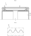
- FIG. 1 is a view showing the structure of an upper portion of a battery according to an embodiment of the present disclosure
- FIG. 2 is a view showing the structure of a gasket of the present disclosure
- FIGS. 3 and 4 are views showing a state in which a gasket of the present disclosure is compressed by a cap
- FIG. 5 is a partial enlarged view of FIG. 1 .
- the battery 1 may include an electrode assembly 10, a battery housing 20, a cap 30, and a gasket 40.
- the battery 1 may be a secondary battery.
- the battery 1 may be a cylindrical battery.
- the electrode assembly 10 may include a first electrode (a positive electrode or a negative electrode), a second electrode (an electrode having an opposite polarity to the first electrode), and a separator interposed between the first electrode and the second electrode.
- the electrode assembly 10 may be, for example, a jelly roll type electrode assembly formed by winding a laminate including the first electrode, the second electrode, and the separator.
- the battery housing 20 may be configured to accommodate the electrode assembly 10 through an opening provided on one side.
- the battery housing 20 may include a conductive metal.
- the battery housing 20 may be electrically connected to the electrode assembly 10.
- An electrolyte may be accommodated in the battery housing 20 together with the electrode assembly 10.
- the cap 30 may be configured to cover the opening of the battery housing 20.
- the cap 30 may include metal.
- a gasket 40 to be described later may be applied to the opening of the battery housing 20 covered by the cap 30, thereby improving the sealing force at the opening of the battery housing 20 covered by the cap 30.
- the gasket 40 may be interposed between the cap 30 and the inner surface of the battery housing 20.
- the gasket 40 may include an elastic material.
- the gasket 40 may include an insulating material.
- insulation between the cap 30 and the battery housing 20 may be achieved.
- the gasket 40 need not necessarily function as an insulator.
- the battery 1 of the present disclosure may have a structure in which the cap 30 is not electrically connected to the electrode assembly 10, and in this case, the cap 30 may not function as a terminal of the battery 1.
- the gasket 40 may be at least partially compressed between the cap 30 and the battery housing 20.
- the gasket 40 may have a protrusion 41.
- the protrusion 41 may be provided on a surface of the outer surface of the gasket 40, which faces the cap 30.
- the protrusion 41 may have a protruding shape in a direction toward the cap 30.
- the structure provided with the protrusion 41 on the outer surface of the gasket 40 may be a structure that appears in a state before the gasket 40 is interposed between the cap 30 and the inner surface of the battery housing 20 and compressed.
- the gasket 40 when viewed in a compressed state between the cap 30 and the battery housing 20, the gasket 40 may have different compression rates in an area where the protrusion 41 is provided and in an area where the protrusion 41 is not provided.
- the compression rate in the area where the protrusion 41 is provided may be formed to be greater than the compression rate in the area where the protrusion 41 is not provided.
- This phenomenon of different compression rates for each area may be common when the gasket 40 in a compressed state has a flat shape as shown in FIG. 3 and when the gasket 40 in a compressed state has a shape where the protrusion 41 partially protrudes as shown in FIG. 4 .
- the protrusion 41 may have a shape in which its cross-sectional area decreases toward the end thereof. When the protrusion 41 has this shape, it is possible to further improve the effect of increasing shear resistance in the area where the protrusion 41 is formed.
- the protrusion 41 may be provided in plurality.
- the plurality of protrusions 41 may be provided along a direction parallel to the direction from the outer side of the battery housing 20 toward the inner side thereof.
- the battery 1 is a cylindrical battery
- the plurality of protrusions 41 may be provided along an approximately radial direction of the battery 1. If the plurality of protrusions 41 are arranged in this manner, the shear resistance due to the plurality of protrusions 41 may be maximized when pressure is applied in the direction of opening the cap 30 according to an increase in the internal pressure of the battery 1. That is, when the internal pressure of the battery 1 increases, an opening pressure may be applied to the interface between the cap 30 and the gasket 40 in the direction from the outer side of the battery 1 toward the inner side thereof. Therefore, it may be advantageous for maximizing shear resistance if the plurality of protrusions 41 are arranged along a direction approximately parallel to the direction in which this opening pressure acts.
- the battery housing 20 may have a bent shape to surround an edge peripheral area of the cap 30 on the opening side.
- the gasket 40 may be configured to be bent into a shape corresponding to the bent shape of the battery housing 20 to surround the edge peripheral area of the cap 30.
- the battery housing 20 of the present disclosure may have a beading portion 21 whose outer peripheral surface is recessed inward.
- the battery housing 20 may have a crimping portion 22 that extends from an upper part of the beading portion 21 and has a bent shape to surround the edge peripheral area of the cap 30.
- FIG. 6 is a view showing the structure of a gasket of the present disclosure, which shows an embodiment different from that of the gasket shown in FIG. 2 .
- the protrusion 41 of the present disclosure may be provided in at least one of an area facing the inner surface of the cap 30 and an area facing the outer surface of the cap 30 in the gasket 40.
- the gasket 40 may be configured to be bent together with the battery housing 20 to surround the edge peripheral area of the cap 30. Accordingly, a portion of the gasket 40 may face the outer surface of the cap 30 (the upper surface of the cap 30 with reference to FIG. 6 ), and another portion may face the inner surface of the cap 30 (the lower surface of the cap 30 with reference to FIG. 6 ).
- the protrusion 41 may be provided in an area facing the outer surface of the cap 30 and/or in an area facing the inner surface of the cap 30.
- the shear resistance at the interface between the gasket 40 and the cap 30 may be maximized.
- venting portion 31 provided in the cap 30 of the present disclosure will be described with reference to FIG. 7 .
- FIG. 7 is a view showing a battery structure having a venting portion.
- the cap 30 may have a venting portion 31 configured to have weaker rigidity compared to the rest of the cap 30.
- the venting portion 31 may be, for example, an area having a thinner thickness compared to the rest of the cap 30.
- the venting portion 31 may be, for example, an area where both surfaces of the cap 30 are notched.
- the venting portion 31 may have an extended shape to form a closed loop surrounding the center of the cap 30.
- the venting portion may be formed continuously or discontinuously.
- the venting timing suitable for the specifications of the battery 1 may be adjusted by appropriately adjusting the breaking strength of the venting portion 31.
- the battery 1 may include a current collector (a first current collector) 50.
- the current collector 50 may be configured to electrically connect the first electrode of the electrode assembly 10 and the battery housing 20.
- the current collector 50 may be disposed on one surface of the electrode assembly 10.
- the current collector 50 may be electrically coupled to a first uncoated portion of the electrode assembly 10.
- the first electrode of the electrode assembly 10 may have the first uncoated portion extending along the winding direction at one end thereof. Accordingly, the first uncoated portion may be provided on the first surface of the electrode assembly 10.
- the first uncoated portion may extend, for example, in an upward direction of the electrode assembly 10.
- the current collector 50 may be interposed between the gasket 40 and the inner surface of the battery housing 20.
- the current collector 50 may be coupled, for example, onto the beading portion 21 (see FIG. 5 ) of the battery housing 20.
- FIG. 8 is a view showing the structure of a lower portion of a battery according to an embodiment of the present disclosure.
- the battery 1 may include a terminal 60.
- the terminal 60 may be configured to be electrically connected to the electrode assembly 10 through a closed portion provided on the opposite side of the opening of the battery housing 20.
- the terminal 60 may be configured to be exposed to the outside of the battery housing 20 through the closed portion of the battery housing 20.
- the terminal 60 may be riveted and fixed on the inner surface of the closed portion of the battery housing 20.
- the terminal 60 may be electrically connected, for example, to a second uncoated portion of the electrode assembly 10.
- the second electrode of the electrode assembly 10 may have the second uncoated portion extending along the winding direction at one end thereof. Accordingly, the second uncoated portion may be provided on the second surface (a surface opposite to the first surface having the first uncoated portion) of the electrode assembly 10. The second uncoated portion may extend, for example, in a downward direction of the electrode assembly 10. As such, the terminal 60 electrically connected to the second electrode of the electrode assembly 10 may be exposed to the outside of the battery housing 20 to function as a second electrode terminal of the battery 1.
- the battery 1 may include an insulating member 70.
- the insulating member 70 may be interposed between the terminal 60 and the battery housing 20.
- the insulating member 70 may include a material having electrical insulating properties and chemical resistance to electrolytes.
- the insulating member 70 may be configured to prevent electrical connection between the terminal 60 and the battery housing 20.
- the insulating member 70 may include a material having electrical insulating properties.
- the terminal 60 and the battery housing 20 may have opposite polarities, and in this case, the insulating member 70 may be configured to prevent a short circuit due to contact between the terminal 60 and the battery housing 20.
- the battery 1 may be configured such that the closed portion of the battery housing 20 functions as a first electrode terminal having a first polarity, and the terminal 60 functions as a second electrode terminal having a second polarity. Therefore, when a plurality of batteries 1 of the present disclosure are connected to configure a battery pack, all electrical connections may be made on one side.
- the insulating member 70 may be deformed together when riveting the terminal 60 inside the battery housing 20.
- the insulating member 70 may be interposed between the inner surface of the closed portion of the battery housing 20 and the terminal 60 according to this deformation.
- the battery 1 may include a current collector (a second current collector) 80.
- the current collector 80 may be provided between the electrode assembly 10 and the terminal 60.
- the current collector 80 may be configured to electrically connect the electrode assembly 10 and the terminal 60.
- the current collector 80 may be disposed between the electrode assembly 10 and the inner surface of the closed portion of the battery housing 20.
- the current collector 80 may be configured to electrically connect the second electrode of the electrode assembly 10 and the terminal 60.
- the current collector 80 may be electrically coupled to the second uncoated portion of the electrode assembly 10.
- the battery 1 may include an insulator 90.
- the insulator 90 may be interposed between the electrode assembly 10 and the closed portion of the battery housing 20.
- the insulator 90 may include a material having electrical insulating properties.
- the insulator 90 may include an insulator hole having an inner diameter equal to or smaller than an outer diameter of the combination of the terminal 60 and the insulating member 70. The terminal 60 may be exposed toward the electrode assembly 10 through the insulator hole.
- FIG. 9 is a view showing an insertion portion provided in a cap of the present disclosure.
- the cap 30 of the present disclosure may include an insertion portion 32.
- the insertion portion 32 may be configured to be inserted into an empty space S formed between a pair of adjacent protrusions 41.
- the insertion portion 32 may have a shape in which its cross-sectional area decreases along a direction toward the gasket 40.
- the insertion portion 32 may be provided in an area facing the gasket 40.
- the insertion portion 32 may be provided on one surface or both surfaces of the cap 30.
- the insertion portion 32 may be provided in plurality, and in this case, each of the plurality of insertion portions 32 may be respectively inserted into a plurality of empty spaces S formed in the gasket 40.
- the insertion portion 32 may be configured to compress the bottom surface of the empty space S of the gasket 40. Alternatively, the insertion portion 32 may be configured to be spaced apart from the bottom surface of the empty space S of the gasket 40. Whether the gasket 40 is compressed by the insertion portion 32 may be determined by the height of the protrusion 41 and/or the height of the insertion portion 32.
- the protrusion 41 may function as a stopper during movement of the insertion portion 32 inwardly along an approximately radial direction of the battery 1, due to the matching structure of the cap 30 and the gasket 40.
- the protrusion 41 of the gasket 40 may be improved in the area where the insertion portion 32 is formed. Therefore, shear stress may be improved across the entire interface between the cap 30 and the gasket 40.
- FIG. 10 is a view showing the structure of a gasket of the present disclosure, which shows an embodiment different from those of the gasket shown in FIGS. 2 and 6 .
- the gasket 40 may have a sub-protrusion 42 that protrudes toward the inner surface of the battery housing 20 based on a state before being compressed.
- the structure provided with the sub-projection 42 on the outer surface of the gasket 40 may be a structure that appears in a state before the gasket 40 is interposed between the cap 30 and the battery housing 20 and compressed.
- the sub-protrusion 42 may not appear while the gasket 40 is interposed between the cap 30 and the battery housing 20 and compressed. That is, the gasket 40 may have an approximately flat shape with no sub-protrusions 42 appearing on the surface facing the battery housing 20 in a compressed state between the cap 30 and the inner surface of the battery housing 20. In contrast, the sub-protrusion 42 may partially appear even while the gasket 40 is interposed between the cap 30 and the battery housing 20 and compressed. When the sub-protrusion 42 partially appears even in a compressed state, an empty space may be formed between a pair of adjacent sub-protrusions 42. The empty space may be surrounded by a pair of adjacent sub-protrusions 42 and the battery housing 20.
- the sub-protrusion 42 may have a shape in which its cross-sectional area decreases toward the end thereof. When the sub-protrusion 42 has this shape, it is possible to further improve the effect of increasing shear resistance in the area where the sub-protrusion 42 is formed.
- the sub-protrusion 42 may be provided in plurality.
- the plurality of sub-protrusions 42 may be provided along a direction parallel to the direction from the outer side of the battery housing 20 toward the inner side thereof.
- the battery 1 is a cylindrical battery
- the plurality of sub-protrusions 42 may be provided along an approximately radial direction of the battery 1. If the plurality of sub-protrusions 42 are arranged in this manner, the shear resistance due to the plurality of sub-protrusions 42 may be maximized when pressure is applied in the direction of opening the cap 30 according to an increase in the internal pressure of the battery 1.
- FIG. 11 is a view showing a battery pack according to an embodiment of the present disclosure.
- the battery pack 3 may include at least one battery 1 of the present disclosure as described above.
- the battery 1 may be accommodated within a pack housing 2.
- the battery pack 3 may include components for electrical connection of the batteries 1 and/or a battery management system (BMS) configured to control charge/discharge of the battery 1.
- BMS battery management system
- FIG. 12 is a view showing a vehicle according to an embodiment of the present disclosure.
- the vehicle 5 includes at least one battery pack 3.
- the vehicle 5 may be configured to operate by receiving power from the battery pack 3.
- the vehicle 5 may be, for example, a hybrid electric vehicle (HEV) or an electric vehicle (EV).
- HEV hybrid electric vehicle
- EV electric vehicle
Landscapes
- Chemical & Material Sciences (AREA)
- Chemical Kinetics & Catalysis (AREA)
- Electrochemistry (AREA)
- General Chemical & Material Sciences (AREA)
- Engineering & Computer Science (AREA)
- Aviation & Aerospace Engineering (AREA)
- Sealing Battery Cases Or Jackets (AREA)
- Battery Mounting, Suspending (AREA)
- Gas Exhaust Devices For Batteries (AREA)
Abstract
Description
- The present disclosure relates to a battery, and a battery pack and a vehicle including the same.
- The present application claims priority to
Korean Patent Application No. 10-2022-0174042 filed on December 13, 2022 - Batteries have high applicability according to product groups and electrical characteristics such as high energy density, and thus are commonly applied not only to portable devices but also to electric vehicles (EVs), hybrid electric vehicles (HEVs), and the like driven by electric power sources.
- Such batteries are attracting attention as a new energy source to improve eco-friendliness and energy efficiency in that it has not only a primary advantage of dramatically reducing the use of fossil fuels, but also no by-products generated from the use of energy.
- Batteries widely used at present include lithium-ion batteries, lithium polymer batteries, nickel cadmium batteries, nickel hydrogen batteries, nickel zinc batteries, and the like. An operating voltage of such a unit battery cell is about 2.5 V to 4.5 V. Therefore, if a higher output voltage is required, a plurality of batteries may be connected in series to configure a battery pack. In addition, depending on the charge/discharge capacity required for the battery pack, a plurality of batteries may be connected in parallel to configure a battery pack. Thus, the number of batteries included in the battery pack and the type of electrical connection may be variously set according to the required output voltage and/or the demanded charge/discharge capacity.
- If an abnormality occurs in the course of using a battery, the internal pressure of the battery may increase, and a thermal event may spread as high-temperature gas and/or flames are generated therein. When such a thermal event occurs in a battery having high capacity and/or high power, it may cause even greater damage.
- In preparation for this, a venting portion may be applied to the battery to release internal gas when the internal pressure increases above a certain level. However, when a sealing portion for sealing the battery is not designed robustly, it may not operate smoothly at predictable times. In addition, when the sealing portion for sealing the battery is not designed robustly, it may be impossible to guide venting in a desired direction through the venting portion. In addition, when the sealing portion for sealing the battery is not designed robustly, there may be a problem that a leak may occur in the sealing portion due to changes in internal pressure even under normal use of the battery, thereby causing leakage of electrolytes.
- Therefore, there is a need to develop a battery configured to prevent the sealing portion of the battery from being broken when an abnormality occurs in the course of using the battery and thus the internal pressure increases abnormally or when the internal pressure increases under normal use.
- The present disclosure is designed to solve the problems of the related art, and therefore the present disclosure is directed to providing a battery configured to prevent the sealing portion of the battery from being broken when an abnormality occurs in the course of using the battery and thus the internal pressure increases abnormally or when the internal pressure increases under normal use.
- However, technical problems to be solved by the present disclosure are not limited to the above-described problems, and other problems not mentioned herein may be clearly understood by those skilled in the art from the following description of the present disclosure.
- A battery according to an embodiment of the present disclosure for solving the above-described problem may include an electrode assembly; a battery housing configured to accommodate the electrode assembly through an opening formed on one side; a cap configured to cover the opening of the battery housing; and a gasket interposed between the cap and the inner surface of the battery housing and at least partially compressed, and having a protrusion on a surface facing the cap that protrudes in a direction toward the cap based on a state before being compressed.
- The protrusion may be provided in plurality, and the plurality of protrusions may be provided along a direction parallel to the direction from the outer side of the battery housing toward the inner side thereof.
- The gasket may have a flat shape with no protrusions appearing on the surface facing the cap while being compressed between the cap and the inner surface of the battery housing.
- An empty space may be formed between adjacent protrusions while the gasket is compressed between the cap and the inner surface of the battery housing.
- The gasket may be configured to have different compression rates in an area where the protrusion is provided and in an area where the protrusion is not provided.
- The battery housing may have a shape bent to surround an edge peripheral area of the cap on the opening side.
- The gasket may be configured to be bent into a shape corresponding to the bent shape of the battery housing to surround an edge peripheral area of the cap.
- The protrusion may be provided in at least one of an area facing the inner surface of the cap and an area facing the outer surface of the cap in the gasket.
- The cap may have a venting portion configured to be weaker compared to the rest of the cap.
- The cap may be configured not to be electrically connected to the electrode assembly.
- The cap may have an insertion portion inserted into an empty space formed between a pair of adjacent protrusions.
- The gasket may have a sub-protrusion that protrudes toward the inner surface of the battery housing based on a state before being compressed.
- A battery pack according to an embodiment of the present disclosure may include the battery.
- A vehicle according to an embodiment of the present disclosure may include the battery pack.
- According to one aspect of the present disclosure, it is possible to prevent a sealing portion of a battery from being broken when an abnormality occurs in the course of using the battery and thus the internal pressure increases abnormally or when the internal pressure increases under normal use.
- However, the advantageous effects to be obtained by the present disclosure are not limited to the above-described effects, and other advantageous effects not mentioned herein may be clearly understood by those skilled in the art from the following description of the present disclosure.
- The accompanying drawings illustrate a preferred embodiment of the present disclosure and together with the foregoing disclosure, serve to provide further understanding of the technical features of the present disclosure, and thus the present disclosure is not construed as being limited to the drawing.
-
FIG. 1 is a view showing the structure of an upper portion of a battery according to an embodiment of the present disclosure. -
FIG. 2 is a view showing the structure of a gasket of the present disclosure. -
FIGS. 3 and 4 are views showing a state in which a gasket of the present disclosure is compressed by a cap. -
FIG. 5 is a partial enlarged view ofFIG. 1 . -
FIG. 6 is a view showing the structure of a gasket of the present disclosure, which shows an embodiment different from that of the gasket shown inFIG. 2 . -
FIG. 7 is a view showing a battery structure having a venting portion. -
FIG. 8 is a view showing the structure of a lower portion of a battery according to an embodiment of the present disclosure. -
FIG. 9 is a view showing an insertion portion provided in a cap of the present disclosure. -
FIG. 10 is a view showing the structure of a gasket of the present disclosure, which shows an embodiment different from those of the gasket shown inFIGS. 2 and6 . -
FIG. 11 is a view showing a battery pack according to an embodiment of the present disclosure. -
FIG. 12 is a view showing a vehicle according to an embodiment of the present disclosure. - Hereinafter, preferred embodiments of the present disclosure will be described in detail with reference to the accompanying drawings. Prior to the description, it should be understood that the terms used in the specification and the appended claims should not be construed as limited to general and dictionary meanings, but interpreted based on the meanings and concepts corresponding to technical aspects of the present disclosure on the basis of the principle that the inventor is allowed to define terms appropriately for the best explanation. Therefore, the embodiments described in this specification and the configurations shown in the drawings are only one of the most preferred embodiments of the present disclosure, not intended to entirely represent the technical aspects of the present disclosure, so it should be understood that various equivalents and modifications may be made thereto at the time of filing the present application.
- A
battery 1 according to an embodiment of the present disclosure will be described with reference toFIGS. 1 to 5 . -
FIG. 1 is a view showing the structure of an upper portion of a battery according to an embodiment of the present disclosure,FIG. 2 is a view showing the structure of a gasket of the present disclosure,FIGS. 3 and 4 are views showing a state in which a gasket of the present disclosure is compressed by a cap, andFIG. 5 is a partial enlarged view ofFIG. 1 . - First, referring to
FIGS. 1 to 4 , thebattery 1 according to an embodiment of the present disclosure may include anelectrode assembly 10, abattery housing 20, acap 30, and agasket 40. Thebattery 1 may be a secondary battery. Thebattery 1 may be a cylindrical battery. - The
electrode assembly 10 may include a first electrode (a positive electrode or a negative electrode), a second electrode (an electrode having an opposite polarity to the first electrode), and a separator interposed between the first electrode and the second electrode. Theelectrode assembly 10 may be, for example, a jelly roll type electrode assembly formed by winding a laminate including the first electrode, the second electrode, and the separator. - The
battery housing 20 may be configured to accommodate theelectrode assembly 10 through an opening provided on one side. Thebattery housing 20 may include a conductive metal. Thebattery housing 20 may be electrically connected to theelectrode assembly 10. An electrolyte may be accommodated in thebattery housing 20 together with theelectrode assembly 10. - The
cap 30 may be configured to cover the opening of thebattery housing 20. Thecap 30 may include metal. Agasket 40 to be described later may be applied to the opening of thebattery housing 20 covered by thecap 30, thereby improving the sealing force at the opening of thebattery housing 20 covered by thecap 30. - The
gasket 40 may be interposed between thecap 30 and the inner surface of thebattery housing 20. Thegasket 40 may include an elastic material. Thegasket 40 may include an insulating material. When thegasket 40 functions as an insulator, insulation between thecap 30 and thebattery housing 20 may be achieved. However, in the present disclosure, thegasket 40 need not necessarily function as an insulator. Thebattery 1 of the present disclosure may have a structure in which thecap 30 is not electrically connected to theelectrode assembly 10, and in this case, thecap 30 may not function as a terminal of thebattery 1. - The
gasket 40 may be at least partially compressed between thecap 30 and thebattery housing 20. Thegasket 40 may have aprotrusion 41. Theprotrusion 41 may be provided on a surface of the outer surface of thegasket 40, which faces thecap 30. Theprotrusion 41 may have a protruding shape in a direction toward thecap 30. - The structure provided with the
protrusion 41 on the outer surface of thegasket 40 may be a structure that appears in a state before thegasket 40 is interposed between thecap 30 and the inner surface of thebattery housing 20 and compressed. - The
protrusion 41 may not appear while thegasket 40 is interposed between thecap 30 and thebattery housing 20 and compressed as shown inFIG. 3 . That is, thegasket 40 may have an approximately flat shape with noprotrusions 41 appearing on the surface facing thecap 30 in a compressed state between thecap 30 and the inner surface of thebattery housing 20. In contrast, theprotrusion 41 may partially appear even while thegasket 40 is interposed between thecap 30 and thebattery housing 20 and compressed as shown inFIG. 4 . As shown inFIG. 4 , when theprotrusion 41 partially appears even in a compressed state, an empty space S may be formed between a pair ofadjacent protrusions 41. The empty space S may be surrounded by a pair ofadjacent protrusions 41 and thecap 30. - Meanwhile, when viewed in a compressed state between the
cap 30 and thebattery housing 20, thegasket 40 may have different compression rates in an area where theprotrusion 41 is provided and in an area where theprotrusion 41 is not provided. In thegasket 40, the compression rate in the area where theprotrusion 41 is provided may be formed to be greater than the compression rate in the area where theprotrusion 41 is not provided. - This phenomenon of different compression rates for each area may be common when the
gasket 40 in a compressed state has a flat shape as shown inFIG. 3 and when thegasket 40 in a compressed state has a shape where theprotrusion 41 partially protrudes as shown inFIG. 4 . - When the
gasket 40 is provided with theprotrusion 41 in this way, shear resistance formed between thegasket 40 and thecap 30 in the area where theprotrusion 41 is formed may increase. Theprotrusion 41 may have a shape in which its cross-sectional area decreases toward the end thereof. When theprotrusion 41 has this shape, it is possible to further improve the effect of increasing shear resistance in the area where theprotrusion 41 is formed. - The
protrusion 41 may be provided in plurality. In this case, the plurality ofprotrusions 41 may be provided along a direction parallel to the direction from the outer side of thebattery housing 20 toward the inner side thereof. When thebattery 1 is a cylindrical battery, the plurality ofprotrusions 41 may be provided along an approximately radial direction of thebattery 1. If the plurality ofprotrusions 41 are arranged in this manner, the shear resistance due to the plurality ofprotrusions 41 may be maximized when pressure is applied in the direction of opening thecap 30 according to an increase in the internal pressure of thebattery 1. That is, when the internal pressure of thebattery 1 increases, an opening pressure may be applied to the interface between thecap 30 and thegasket 40 in the direction from the outer side of thebattery 1 toward the inner side thereof. Therefore, it may be advantageous for maximizing shear resistance if the plurality ofprotrusions 41 are arranged along a direction approximately parallel to the direction in which this opening pressure acts. - Referring to
FIG. 5 , thebattery housing 20 may have a bent shape to surround an edge peripheral area of thecap 30 on the opening side. In this case, thegasket 40 may be configured to be bent into a shape corresponding to the bent shape of thebattery housing 20 to surround the edge peripheral area of thecap 30. - For example, the
battery housing 20 of the present disclosure may have abeading portion 21 whose outer peripheral surface is recessed inward. Thebattery housing 20 may have a crimpingportion 22 that extends from an upper part of thebeading portion 21 and has a bent shape to surround the edge peripheral area of thecap 30. - Next, referring to
FIG. 6 together withFIG. 5 , the formation position of theprotrusion 41 will be described in the case where thebattery housing 20 and thegasket 40 are configured to be bent together to surround the edge peripheral area of thecap 30 as described above. -
FIG. 6 is a view showing the structure of a gasket of the present disclosure, which shows an embodiment different from that of the gasket shown inFIG. 2 . - Referring to
FIG. 6 together withFIG. 5 , theprotrusion 41 of the present disclosure may be provided in at least one of an area facing the inner surface of thecap 30 and an area facing the outer surface of thecap 30 in thegasket 40. - As previously described, the
gasket 40 may be configured to be bent together with thebattery housing 20 to surround the edge peripheral area of thecap 30. Accordingly, a portion of thegasket 40 may face the outer surface of the cap 30 (the upper surface of thecap 30 with reference toFIG. 6 ), and another portion may face the inner surface of the cap 30 (the lower surface of thecap 30 with reference toFIG. 6 ). In this case, theprotrusion 41 may be provided in an area facing the outer surface of thecap 30 and/or in an area facing the inner surface of thecap 30. - When the
protrusion 41 is provided in both the area facing the outer surface of thecap 30 and the area facing the inner surface of thecap 30, the shear resistance at the interface between thegasket 40 and thecap 30 may be maximized. - Next, a venting
portion 31 provided in thecap 30 of the present disclosure will be described with reference toFIG. 7 . -
FIG. 7 is a view showing a battery structure having a venting portion. - Referring to
FIG. 7 , thecap 30 may have a ventingportion 31 configured to have weaker rigidity compared to the rest of thecap 30. The ventingportion 31 may be, for example, an area having a thinner thickness compared to the rest of thecap 30. The ventingportion 31 may be, for example, an area where both surfaces of thecap 30 are notched. The ventingportion 31 may have an extended shape to form a closed loop surrounding the center of thecap 30. The venting portion may be formed continuously or discontinuously. - As such, when the
battery 1 of the present disclosure has the ventingportion 31, it is possible to prevent the internal pressure of thebattery 1 from increasing above a certain level even if an abnormality occurs in thebattery 1. In the present disclosure, the venting timing suitable for the specifications of thebattery 1 may be adjusted by appropriately adjusting the breaking strength of the ventingportion 31. However, in order to adjust the venting timing using the ventingportion 31, it is important to ensure that no leak occurs in areas other than the ventingportion 31 until the preset venting pressure is reached. Therefore, as described above, it is necessary to increase the shear resistance at the interface between thegasket 40 and thecap 30 by applying thegasket 40 having theprotrusion 41. - Meanwhile, referring to
FIGS. 1 and7 , thebattery 1 according to an embodiment of the present disclosure may include a current collector (a first current collector) 50. Thecurrent collector 50 may be configured to electrically connect the first electrode of theelectrode assembly 10 and thebattery housing 20. Thecurrent collector 50 may be disposed on one surface of theelectrode assembly 10. Thecurrent collector 50 may be electrically coupled to a first uncoated portion of theelectrode assembly 10. The first electrode of theelectrode assembly 10 may have the first uncoated portion extending along the winding direction at one end thereof. Accordingly, the first uncoated portion may be provided on the first surface of theelectrode assembly 10. The first uncoated portion may extend, for example, in an upward direction of theelectrode assembly 10. Thecurrent collector 50 may be interposed between thegasket 40 and the inner surface of thebattery housing 20. Thecurrent collector 50 may be coupled, for example, onto the beading portion 21 (seeFIG. 5 ) of thebattery housing 20. - Next, the structure of a lower portion of the
battery 1 according to an embodiment of the present disclosure will be described with reference toFIG. 8 . -
FIG. 8 is a view showing the structure of a lower portion of a battery according to an embodiment of the present disclosure. - Referring to
FIG. 8 , thebattery 1 according to an embodiment of the present disclosure may include a terminal 60. - The terminal 60 may be configured to be electrically connected to the
electrode assembly 10 through a closed portion provided on the opposite side of the opening of thebattery housing 20. The terminal 60 may be configured to be exposed to the outside of thebattery housing 20 through the closed portion of thebattery housing 20. The terminal 60 may be riveted and fixed on the inner surface of the closed portion of thebattery housing 20. - The terminal 60 may be electrically connected, for example, to a second uncoated portion of the
electrode assembly 10. The second electrode of theelectrode assembly 10 may have the second uncoated portion extending along the winding direction at one end thereof. Accordingly, the second uncoated portion may be provided on the second surface (a surface opposite to the first surface having the first uncoated portion) of theelectrode assembly 10. The second uncoated portion may extend, for example, in a downward direction of theelectrode assembly 10. As such, the terminal 60 electrically connected to the second electrode of theelectrode assembly 10 may be exposed to the outside of thebattery housing 20 to function as a second electrode terminal of thebattery 1. - The
battery 1 according to an embodiment of the present disclosure may include an insulatingmember 70. The insulatingmember 70 may be interposed between the terminal 60 and thebattery housing 20. The insulatingmember 70 may include a material having electrical insulating properties and chemical resistance to electrolytes. The insulatingmember 70 may be configured to prevent electrical connection between the terminal 60 and thebattery housing 20. The insulatingmember 70 may include a material having electrical insulating properties. The terminal 60 and thebattery housing 20 may have opposite polarities, and in this case, the insulatingmember 70 may be configured to prevent a short circuit due to contact between the terminal 60 and thebattery housing 20. In this way, thebattery 1 may be configured such that the closed portion of thebattery housing 20 functions as a first electrode terminal having a first polarity, and the terminal 60 functions as a second electrode terminal having a second polarity. Therefore, when a plurality ofbatteries 1 of the present disclosure are connected to configure a battery pack, all electrical connections may be made on one side. - The insulating
member 70 may be deformed together when riveting the terminal 60 inside thebattery housing 20. The insulatingmember 70 may be interposed between the inner surface of the closed portion of thebattery housing 20 and the terminal 60 according to this deformation. - The
battery 1 according to an embodiment of the present disclosure may include a current collector (a second current collector) 80. Thecurrent collector 80 may be provided between theelectrode assembly 10 and the terminal 60. Thecurrent collector 80 may be configured to electrically connect theelectrode assembly 10 and the terminal 60. Thecurrent collector 80 may be disposed between theelectrode assembly 10 and the inner surface of the closed portion of thebattery housing 20. Thecurrent collector 80 may be configured to electrically connect the second electrode of theelectrode assembly 10 and the terminal 60. Thecurrent collector 80 may be electrically coupled to the second uncoated portion of theelectrode assembly 10. - The
battery 1 according to an embodiment of the present disclosure may include aninsulator 90. Theinsulator 90 may be interposed between theelectrode assembly 10 and the closed portion of thebattery housing 20. Theinsulator 90 may include a material having electrical insulating properties. Theinsulator 90 may include an insulator hole having an inner diameter equal to or smaller than an outer diameter of the combination of the terminal 60 and the insulatingmember 70. The terminal 60 may be exposed toward theelectrode assembly 10 through the insulator hole. - Next, an embodiment in which an
insertion portion 32 is provided in thecap 30 of the present disclosure will be described with reference toFIG. 9 . -
FIG. 9 is a view showing an insertion portion provided in a cap of the present disclosure. - Referring to
FIG. 9 , thecap 30 of the present disclosure may include aninsertion portion 32. Theinsertion portion 32 may be configured to be inserted into an empty space S formed between a pair ofadjacent protrusions 41. Theinsertion portion 32 may have a shape in which its cross-sectional area decreases along a direction toward thegasket 40. Theinsertion portion 32 may be provided in an area facing thegasket 40. Theinsertion portion 32 may be provided on one surface or both surfaces of thecap 30. Theinsertion portion 32 may be provided in plurality, and in this case, each of the plurality ofinsertion portions 32 may be respectively inserted into a plurality of empty spaces S formed in thegasket 40. - The
insertion portion 32 may be configured to compress the bottom surface of the empty space S of thegasket 40. Alternatively, theinsertion portion 32 may be configured to be spaced apart from the bottom surface of the empty space S of thegasket 40. Whether thegasket 40 is compressed by theinsertion portion 32 may be determined by the height of theprotrusion 41 and/or the height of theinsertion portion 32. - As such, when the
cap 30 of the present disclosure includes theinsertion portion 32, theprotrusion 41 may function as a stopper during movement of theinsertion portion 32 inwardly along an approximately radial direction of thebattery 1, due to the matching structure of thecap 30 and thegasket 40. Alternatively, even if theprotrusion 41 of thegasket 40 does not appear outwardly while thegasket 40 is compressed, the pressing force on thegasket 40 may be improved in the area where theinsertion portion 32 is formed. Therefore, shear stress may be improved across the entire interface between thecap 30 and thegasket 40. - Next, a sub-protrusion 42 provided in the
gasket 40 of the present disclosure will be described with reference toFIG. 10 . -
FIG. 10 is a view showing the structure of a gasket of the present disclosure, which shows an embodiment different from those of the gasket shown inFIGS. 2 and6 . - Referring to
FIG. 10 , thegasket 40 may have a sub-protrusion 42 that protrudes toward the inner surface of thebattery housing 20 based on a state before being compressed. The structure provided with the sub-projection 42 on the outer surface of thegasket 40 may be a structure that appears in a state before thegasket 40 is interposed between thecap 30 and thebattery housing 20 and compressed. - The sub-protrusion 42 may not appear while the
gasket 40 is interposed between thecap 30 and thebattery housing 20 and compressed. That is, thegasket 40 may have an approximately flat shape with no sub-protrusions 42 appearing on the surface facing thebattery housing 20 in a compressed state between thecap 30 and the inner surface of thebattery housing 20. In contrast, thesub-protrusion 42 may partially appear even while thegasket 40 is interposed between thecap 30 and thebattery housing 20 and compressed. When the sub-protrusion 42 partially appears even in a compressed state, an empty space may be formed between a pair ofadjacent sub-protrusions 42. The empty space may be surrounded by a pair ofadjacent sub-protrusions 42 and thebattery housing 20. - When the
gasket 40 is provided with the sub-protrusion 42 in this way, shear resistance formed between thegasket 40 and thebattery housing 20 in the area where thesub-protrusion 42 is formed may increase. The sub-protrusion 42 may have a shape in which its cross-sectional area decreases toward the end thereof. When the sub-protrusion 42 has this shape, it is possible to further improve the effect of increasing shear resistance in the area where thesub-protrusion 42 is formed. - The sub-protrusion 42 may be provided in plurality. In this case, the plurality of
sub-protrusions 42 may be provided along a direction parallel to the direction from the outer side of thebattery housing 20 toward the inner side thereof. When thebattery 1 is a cylindrical battery, the plurality ofsub-protrusions 42 may be provided along an approximately radial direction of thebattery 1. If the plurality ofsub-protrusions 42 are arranged in this manner, the shear resistance due to the plurality ofsub-protrusions 42 may be maximized when pressure is applied in the direction of opening thecap 30 according to an increase in the internal pressure of thebattery 1. That is, when the internal pressure of thebattery 1 increases, an opening pressure may be applied to the interface between thebattery housing 20 and thegasket 40 in the direction from the outer side of thebattery 1 toward the inner side thereof. Therefore, it may be advantageous for maximizing shear resistance if the plurality ofsub-protrusions 42 are arranged along a direction approximately parallel to the direction in which this opening pressure acts. - Next, a
battery pack 3 according to an embodiment of the present disclosure will be described with reference toFIG. 11 . -
FIG. 11 is a view showing a battery pack according to an embodiment of the present disclosure. - Referring to
FIG. 11 , thebattery pack 3 according to an embodiment of the present disclosure may include at least onebattery 1 of the present disclosure as described above. Thebattery 1 may be accommodated within apack housing 2. Thebattery pack 3 may include components for electrical connection of thebatteries 1 and/or a battery management system (BMS) configured to control charge/discharge of thebattery 1. - Next, a
vehicle 5 according to an embodiment of the present disclosure will be described with reference toFIG. 12 . -
FIG. 12 is a view showing a vehicle according to an embodiment of the present disclosure. - Referring to
FIG. 12 , thevehicle 5 according to an embodiment of the present disclosure includes at least onebattery pack 3. Thevehicle 5 may be configured to operate by receiving power from thebattery pack 3. Thevehicle 5 may be, for example, a hybrid electric vehicle (HEV) or an electric vehicle (EV). - The present disclosure has been hereinabove described with regard to a limited number of embodiments and drawings, but the present disclosure is not limited thereto and it is obvious to those skilled in the art that a variety of modifications and changes may be made thereto within the technical aspects of the present disclosure and the equivalent scope of the appended claims.
-
- 1: battery
- 2: pack housing
- 3: battery pack
- 5: vehicle
- 10: electrode assembly
- 20: battery housing
- 21: beading portion
- 22: crimping portion
- 30: cap
- 31: venting portion
- 32: insertion portion
- 40: gasket
- 41: protrusion
- 42: sub-protrusion
- S: empty space
- 50: current collector (first current collector)
- 60: terminal
- 70: insulating member
- 80: current collector (second current collector)
- 90: insulator
Claims (14)
- A battery, comprising:an electrode assembly;a battery housing configured to accommodate the electrode assembly through an opening formed on one side;a cap configured to cover the opening of the battery housing; anda gasket interposed between the cap and the inner surface of the battery housing and at least partially compressed, and having a protrusion on a surface facing the cap that protrudes in a direction toward the cap based on a state before being compressed.
- The battery according to claim 1,
wherein the protrusion is provided in plurality, and the plurality of protrusions are provided along a direction parallel to the direction from the outer side of the battery housing toward the inner side thereof. - The battery according to claim 1,
wherein the gasket has a flat shape with no protrusions appearing on the surface facing the cap while being compressed between the cap and the inner surface of the battery housing. - The battery according to claim 2,
wherein an empty space is formed between adjacent protrusions while the gasket is compressed between the cap and the inner surface of the battery housing. - The battery according to claim 1,
wherein the gasket has different compression rates in an area where the protrusion is provided and in an area where the protrusion is not provided. - The battery according to claim 1,
wherein the battery housing has a shape bent to surround an edge peripheral area of the cap on the opening side. - The battery according to claim 6,
wherein the gasket is bent into a shape corresponding to the bent shape of the battery housing to surround an edge peripheral area of the cap. - The battery according to claim 7,
wherein the protrusion is provided in at least one of an area facing the inner surface of the cap and an area facing the outer surface of the cap in the gasket. - The battery according to claim 1,
wherein the cap has a venting portion configured to be weaker compared to the rest of the cap. - The battery according to claim 1,
wherein the cap is not electrically connected to the electrode assembly. - The battery according to claim 2,
wherein the cap has an insertion portion inserted into an empty space formed between a pair of adjacent protrusions. - The battery according to claim 1,
wherein the gasket has a sub-protrusion that protrudes toward the inner surface of the battery housing based on a state before being compressed. - A battery pack comprising a battery according to any one of claims 1 to 12.
- A vehicle comprising a battery pack according to claim 13.
Applications Claiming Priority (2)
| Application Number | Priority Date | Filing Date | Title |
|---|---|---|---|
| KR20220174042 | 2022-12-13 | ||
| PCT/KR2023/020556 WO2024128806A1 (en) | 2022-12-13 | 2023-12-13 | Battery, and battery pack and vehicle comprising battery |
Publications (2)
| Publication Number | Publication Date |
|---|---|
| EP4571964A1 true EP4571964A1 (en) | 2025-06-18 |
| EP4571964A4 EP4571964A4 (en) | 2026-02-11 |
Family
ID=91485363
Family Applications (1)
| Application Number | Title | Priority Date | Filing Date |
|---|---|---|---|
| EP23904006.6A Pending EP4571964A4 (en) | 2022-12-13 | 2023-12-13 | BATTERY AND BATTERY PACK AND VEHICLE WITH THE BATTERY |
Country Status (6)
| Country | Link |
|---|---|
| EP (1) | EP4571964A4 (en) |
| JP (1) | JP2025534395A (en) |
| KR (2) | KR102924458B1 (en) |
| CN (1) | CN119013827A (en) |
| CA (1) | CA3270174A1 (en) |
| WO (1) | WO2024128806A1 (en) |
Families Citing this family (1)
| Publication number | Priority date | Publication date | Assignee | Title |
|---|---|---|---|---|
| KR20260057765A (en) * | 2024-10-21 | 2026-04-28 | 한화솔루션 주식회사 | Laminated separator structure and laminating method for separator |
Family Cites Families (13)
| Publication number | Priority date | Publication date | Assignee | Title |
|---|---|---|---|---|
| US5725967A (en) * | 1995-08-15 | 1998-03-10 | Micron Communications, Inc. | Battery container and method of manufacture |
| JPH10199495A (en) * | 1997-01-09 | 1998-07-31 | Mitsubishi Cable Ind Ltd | Sealed structure of sealed battery and gasket used for it |
| KR20050052218A (en) * | 2003-11-29 | 2005-06-02 | 삼성에스디아이 주식회사 | Gasket and secondary battery utilizing the same |
| KR100686827B1 (en) * | 2005-07-11 | 2007-02-26 | 삼성에스디아이 주식회사 | Lithium secondary battery |
| WO2008059829A1 (en) * | 2006-11-16 | 2008-05-22 | Kitagawa Seiki Kabushiki Kaisha | Electrochemical cell |
| JP2008147638A (en) * | 2006-11-16 | 2008-06-26 | Kitagawa Elaborate Mach Co Ltd | Electrochemical cell |
| KR20110029061A (en) * | 2009-09-14 | 2011-03-22 | 주식회사 엘지화학 | Secondary battery |
| KR101175008B1 (en) * | 2010-09-16 | 2012-08-17 | 삼성에스디아이 주식회사 | Cylinderical Rechargeable Battery |
| WO2013009148A2 (en) * | 2011-07-13 | 2013-01-17 | 주식회사 엘지화학 | Cylindrical rechargeable battery |
| KR102158089B1 (en) * | 2016-01-20 | 2020-09-21 | 주식회사 엘지화학 | Cylindrical battery can, secondary battery comprising the same and fabricating methods thereof |
| KR102746304B1 (en) * | 2019-05-08 | 2024-12-26 | 주식회사 엘지에너지솔루션 | Gasket for a Cylindrical Battery to Prevent Corrosion of Battery Case and Cylindrical Battery Comprising the Same |
| KR20220105112A (en) * | 2021-01-19 | 2022-07-26 | 주식회사 엘지에너지솔루션 | Cylindrical secondary battery cell, and battery pack and vehicle including the same |
| PL4047703T3 (en) * | 2021-01-19 | 2024-04-29 | Lg Energy Solution, Ltd. | Electrode terminal, cylindrical battery cell, battery pack and vehicle |
-
2023
- 2023-12-13 CN CN202380033390.XA patent/CN119013827A/en active Pending
- 2023-12-13 EP EP23904006.6A patent/EP4571964A4/en active Pending
- 2023-12-13 WO PCT/KR2023/020556 patent/WO2024128806A1/en not_active Ceased
- 2023-12-13 CA CA3270174A patent/CA3270174A1/en active Pending
- 2023-12-13 KR KR1020230181133A patent/KR102924458B1/en active Active
- 2023-12-13 JP JP2025518861A patent/JP2025534395A/en active Pending
-
2026
- 2026-02-02 KR KR1020260020896A patent/KR20260020454A/en active Pending
Also Published As
| Publication number | Publication date |
|---|---|
| CA3270174A1 (en) | 2025-04-16 |
| CN119013827A (en) | 2024-11-22 |
| EP4571964A4 (en) | 2026-02-11 |
| KR20260020454A (en) | 2026-02-11 |
| JP2025534395A (en) | 2025-10-15 |
| KR102924458B1 (en) | 2026-02-06 |
| WO2024128806A1 (en) | 2024-06-20 |
| KR20240088628A (en) | 2024-06-20 |
Similar Documents
| Publication | Publication Date | Title |
|---|---|---|
| EP2273587B1 (en) | Rechargeable battery | |
| EP2284932A1 (en) | Rechargeable battery | |
| EP2624327A1 (en) | Rechargeable battery | |
| EP2733770A1 (en) | Rechargeable battery module | |
| KR20230032898A (en) | Cylindrical battery cell, and battery pack and vehicle including the same | |
| WO2022240156A1 (en) | Secondary battery | |
| EP2048723A1 (en) | Battery module | |
| EP4539232A1 (en) | Battery, and battery pack and vehicle comprising same | |
| KR20160123854A (en) | Rechargeable battery | |
| EP2424007A1 (en) | Rechargeable battery | |
| KR20140124247A (en) | Rechargeable battery | |
| KR20260020454A (en) | Battery, and battery pack and vehicle comprising the battery | |
| KR101483700B1 (en) | Secondary battery and battery pack including the same | |
| EP4307456A1 (en) | Battery pack and vehicle comprising same | |
| US12489133B2 (en) | Button-type secondary battery | |
| KR101446153B1 (en) | Cap assembly for secondary battery, secondary battery using the same, and method for manufacturing the secondary battery | |
| KR20160015778A (en) | A sylnder type battery having enhanced vibration resistant property | |
| KR20240087594A (en) | Battery, and Battery pack and Vehicle comprising the battery | |
| KR101473392B1 (en) | Secondary battery and method for manufacturing the same | |
| EP4632894A1 (en) | Battery, battery pack and vehicle comprising battery, and method for manufacturing battery | |
| EP4697465A1 (en) | Battery, and battery pack and vehicle including same | |
| EP4513664A1 (en) | Battery, and battery pack and vehicle comprising battery | |
| EP4712227A1 (en) | Gasket, battery cell, battery pack and vehicle comprising same | |
| EP4517989A1 (en) | Battery, and battery pack and vehicle comprising same | |
| KR20230094986A (en) | Battery cell, and Battery pack and vehicle comprising the same |
Legal Events
| Date | Code | Title | Description |
|---|---|---|---|
| STAA | Information on the status of an ep patent application or granted ep patent |
Free format text: STATUS: THE INTERNATIONAL PUBLICATION HAS BEEN MADE |
|
| PUAI | Public reference made under article 153(3) epc to a published international application that has entered the european phase |
Free format text: ORIGINAL CODE: 0009012 |
|
| STAA | Information on the status of an ep patent application or granted ep patent |
Free format text: STATUS: REQUEST FOR EXAMINATION WAS MADE |
|
| 17P | Request for examination filed |
Effective date: 20250311 |
|
| AK | Designated contracting states |
Kind code of ref document: A1 Designated state(s): AL AT BE BG CH CY CZ DE DK EE ES FI FR GB GR HR HU IE IS IT LI LT LU LV MC ME MK MT NL NO PL PT RO RS SE SI SK SM TR |
|
| REG | Reference to a national code |
Ref country code: DE Ref legal event code: R079 Free format text: PREVIOUS MAIN CLASS: H01M0050167000 Ipc: H01M0050147000 |
|
| A4 | Supplementary search report drawn up and despatched |
Effective date: 20260109 |
|
| RIC1 | Information provided on ipc code assigned before grant |
Ipc: H01M 50/147 20210101AFI20260102BHEP |
|
| DAV | Request for validation of the european patent (deleted) | ||
| DAX | Request for extension of the european patent (deleted) |