EP4571916A1 - Solid electrolyte-electrode composite, method for manufacturing solid electrolyte-electrode composite, and all-solid-state battery comprising same solid electrolyte-electrode composite - Google Patents
Solid electrolyte-electrode composite, method for manufacturing solid electrolyte-electrode composite, and all-solid-state battery comprising same solid electrolyte-electrode composite Download PDFInfo
- Publication number
- EP4571916A1 EP4571916A1 EP23853097.6A EP23853097A EP4571916A1 EP 4571916 A1 EP4571916 A1 EP 4571916A1 EP 23853097 A EP23853097 A EP 23853097A EP 4571916 A1 EP4571916 A1 EP 4571916A1
- Authority
- EP
- European Patent Office
- Prior art keywords
- electrode
- solid electrolyte
- electrolyte
- composite
- solid
- Prior art date
- Legal status (The legal status is an assumption and is not a legal conclusion. Google has not performed a legal analysis and makes no representation as to the accuracy of the status listed.)
- Pending
Links
Images

Classifications
-
- H—ELECTRICITY
- H01—ELECTRIC ELEMENTS
- H01M—PROCESSES OR MEANS, e.g. BATTERIES, FOR THE DIRECT CONVERSION OF CHEMICAL ENERGY INTO ELECTRICAL ENERGY
- H01M4/00—Electrodes
- H01M4/02—Electrodes composed of, or comprising, active material
- H01M4/36—Selection of substances as active materials, active masses, active liquids
- H01M4/48—Selection of substances as active materials, active masses, active liquids of inorganic oxides or hydroxides
- H01M4/50—Selection of substances as active materials, active masses, active liquids of inorganic oxides or hydroxides of manganese
- H01M4/505—Selection of substances as active materials, active masses, active liquids of inorganic oxides or hydroxides of manganese of mixed oxides or hydroxides containing manganese for inserting or intercalating light metals, e.g. LiMn2O4 or LiMn2OxFy
-
- H—ELECTRICITY
- H01—ELECTRIC ELEMENTS
- H01M—PROCESSES OR MEANS, e.g. BATTERIES, FOR THE DIRECT CONVERSION OF CHEMICAL ENERGY INTO ELECTRICAL ENERGY
- H01M10/00—Secondary cells; Manufacture thereof
- H01M10/05—Accumulators with non-aqueous electrolyte
- H01M10/052—Li-accumulators
-
- H—ELECTRICITY
- H01—ELECTRIC ELEMENTS
- H01M—PROCESSES OR MEANS, e.g. BATTERIES, FOR THE DIRECT CONVERSION OF CHEMICAL ENERGY INTO ELECTRICAL ENERGY
- H01M10/00—Secondary cells; Manufacture thereof
- H01M10/05—Accumulators with non-aqueous electrolyte
- H01M10/052—Li-accumulators
- H01M10/0525—Rocking-chair batteries, i.e. batteries with lithium insertion or intercalation in both electrodes; Lithium-ion batteries
-
- H—ELECTRICITY
- H01—ELECTRIC ELEMENTS
- H01M—PROCESSES OR MEANS, e.g. BATTERIES, FOR THE DIRECT CONVERSION OF CHEMICAL ENERGY INTO ELECTRICAL ENERGY
- H01M10/00—Secondary cells; Manufacture thereof
- H01M10/05—Accumulators with non-aqueous electrolyte
- H01M10/056—Accumulators with non-aqueous electrolyte characterised by the materials used as electrolytes, e.g. mixed inorganic/organic electrolytes
- H01M10/0564—Accumulators with non-aqueous electrolyte characterised by the materials used as electrolytes, e.g. mixed inorganic/organic electrolytes the electrolyte being constituted of organic materials only
- H01M10/0565—Polymeric materials, e.g. gel-type or solid-type
-
- H—ELECTRICITY
- H01—ELECTRIC ELEMENTS
- H01M—PROCESSES OR MEANS, e.g. BATTERIES, FOR THE DIRECT CONVERSION OF CHEMICAL ENERGY INTO ELECTRICAL ENERGY
- H01M10/00—Secondary cells; Manufacture thereof
- H01M10/05—Accumulators with non-aqueous electrolyte
- H01M10/058—Construction or manufacture
- H01M10/0585—Construction or manufacture of accumulators having only flat construction elements, i.e. flat positive electrodes, flat negative electrodes and flat separators
-
- H—ELECTRICITY
- H01—ELECTRIC ELEMENTS
- H01M—PROCESSES OR MEANS, e.g. BATTERIES, FOR THE DIRECT CONVERSION OF CHEMICAL ENERGY INTO ELECTRICAL ENERGY
- H01M10/00—Secondary cells; Manufacture thereof
- H01M10/42—Methods or arrangements for servicing or maintenance of secondary cells or secondary half-cells
- H01M10/4235—Safety or regulating additives or arrangements in electrodes, separators or electrolyte
-
- H—ELECTRICITY
- H01—ELECTRIC ELEMENTS
- H01M—PROCESSES OR MEANS, e.g. BATTERIES, FOR THE DIRECT CONVERSION OF CHEMICAL ENERGY INTO ELECTRICAL ENERGY
- H01M4/00—Electrodes
- H01M4/02—Electrodes composed of, or comprising, active material
- H01M4/13—Electrodes for accumulators with non-aqueous electrolyte, e.g. for lithium-accumulators; Processes of manufacture thereof
- H01M4/131—Electrodes based on mixed oxides or hydroxides, or on mixtures of oxides or hydroxides, e.g. LiCoOx
-
- H—ELECTRICITY
- H01—ELECTRIC ELEMENTS
- H01M—PROCESSES OR MEANS, e.g. BATTERIES, FOR THE DIRECT CONVERSION OF CHEMICAL ENERGY INTO ELECTRICAL ENERGY
- H01M4/00—Electrodes
- H01M4/02—Electrodes composed of, or comprising, active material
- H01M4/13—Electrodes for accumulators with non-aqueous electrolyte, e.g. for lithium-accumulators; Processes of manufacture thereof
- H01M4/133—Electrodes based on carbonaceous material, e.g. graphite-intercalation compounds or CFx
-
- H—ELECTRICITY
- H01—ELECTRIC ELEMENTS
- H01M—PROCESSES OR MEANS, e.g. BATTERIES, FOR THE DIRECT CONVERSION OF CHEMICAL ENERGY INTO ELECTRICAL ENERGY
- H01M4/00—Electrodes
- H01M4/02—Electrodes composed of, or comprising, active material
- H01M4/13—Electrodes for accumulators with non-aqueous electrolyte, e.g. for lithium-accumulators; Processes of manufacture thereof
- H01M4/139—Processes of manufacture
- H01M4/1391—Processes of manufacture of electrodes based on mixed oxides or hydroxides, or on mixtures of oxides or hydroxides, e.g. LiCoOx
-
- H—ELECTRICITY
- H01—ELECTRIC ELEMENTS
- H01M—PROCESSES OR MEANS, e.g. BATTERIES, FOR THE DIRECT CONVERSION OF CHEMICAL ENERGY INTO ELECTRICAL ENERGY
- H01M4/00—Electrodes
- H01M4/02—Electrodes composed of, or comprising, active material
- H01M4/13—Electrodes for accumulators with non-aqueous electrolyte, e.g. for lithium-accumulators; Processes of manufacture thereof
- H01M4/139—Processes of manufacture
- H01M4/1393—Processes of manufacture of electrodes based on carbonaceous material, e.g. graphite-intercalation compounds or CFx
-
- H—ELECTRICITY
- H01—ELECTRIC ELEMENTS
- H01M—PROCESSES OR MEANS, e.g. BATTERIES, FOR THE DIRECT CONVERSION OF CHEMICAL ENERGY INTO ELECTRICAL ENERGY
- H01M4/00—Electrodes
- H01M4/02—Electrodes composed of, or comprising, active material
- H01M4/36—Selection of substances as active materials, active masses, active liquids
- H01M4/48—Selection of substances as active materials, active masses, active liquids of inorganic oxides or hydroxides
- H01M4/52—Selection of substances as active materials, active masses, active liquids of inorganic oxides or hydroxides of nickel, cobalt or iron
- H01M4/525—Selection of substances as active materials, active masses, active liquids of inorganic oxides or hydroxides of nickel, cobalt or iron of mixed oxides or hydroxides containing iron, cobalt or nickel for inserting or intercalating light metals, e.g. LiNiO2, LiCoO2 or LiCoOxFy
-
- H—ELECTRICITY
- H01—ELECTRIC ELEMENTS
- H01M—PROCESSES OR MEANS, e.g. BATTERIES, FOR THE DIRECT CONVERSION OF CHEMICAL ENERGY INTO ELECTRICAL ENERGY
- H01M4/00—Electrodes
- H01M4/02—Electrodes composed of, or comprising, active material
- H01M4/36—Selection of substances as active materials, active masses, active liquids
- H01M4/58—Selection of substances as active materials, active masses, active liquids of inorganic compounds other than oxides or hydroxides, e.g. sulfides, selenides, tellurides, halogenides or LiCoFy; of polyanionic structures, e.g. phosphates, silicates or borates
- H01M4/5825—Oxygenated metallic salts or polyanionic structures, e.g. borates, phosphates, silicates, olivines
-
- Y—GENERAL TAGGING OF NEW TECHNOLOGICAL DEVELOPMENTS; GENERAL TAGGING OF CROSS-SECTIONAL TECHNOLOGIES SPANNING OVER SEVERAL SECTIONS OF THE IPC; TECHNICAL SUBJECTS COVERED BY FORMER USPC CROSS-REFERENCE ART COLLECTIONS [XRACs] AND DIGESTS
- Y02—TECHNOLOGIES OR APPLICATIONS FOR MITIGATION OR ADAPTATION AGAINST CLIMATE CHANGE
- Y02E—REDUCTION OF GREENHOUSE GAS [GHG] EMISSIONS, RELATED TO ENERGY GENERATION, TRANSMISSION OR DISTRIBUTION
- Y02E60/00—Enabling technologies; Technologies with a potential or indirect contribution to GHG emissions mitigation
- Y02E60/10—Energy storage using batteries
Definitions
- the present invention relates to a solid electrolyte-electrode composite, a method for manufacturing the solid electrolyte-electrode composite and an all-solid battery comprising the solid electrolyte-electrode composite.
- Lithium secondary batteries can be miniaturized and have high energy density and working voltage, and accordingly, are applied in various fields such as mobile devices, electronic products and electric vehicles. As the applications of lithium secondary batteries become more diverse, the required conditions of physical properties increase gradually, particularly, the development on lithium secondary batteries which are stably operated in diverse environments is being required.
- secondary batteries are manufactured by installing an electrode assembly composed of a negative electrode, a positive electrode and a separator in a case having a certain space of a cylindrical, a prismatic, or a pouch type.
- the conventional electrolyte for electrochemical devices a liquid type electrolyte in which a salt is dissolved in a non-aqueous organic solvent has been widely used.
- the liquid electrolyte induces the deterioration of an electrode material, has strong possibility of volatilizing an organic solvent, produces combustion or the like due to the elevation of the temperature, and has concerns on leakage, and there are difficulties in accomplishing electrochemical devices of diverse types, which require safety.
- the present invention is to solve the above-described defects and to provide a solid electrolyte-electrode composite in which complete curing is achieved, and an unreacted monomer is not detected.
- an all-solid battery comprising the solid electrolyte-electrode composite.
- the present invention provides a solid electrolyte-electrode composite, which does not show a peak in a wavenumber region of 1,700 cm -1 to 1,600 cm -1 by Fourier-Transform Infrared Spectroscopic analysis.
- the present invention provides a method for preparing a solid electrolyte-electrode composite, comprising: immersing an electrode in an electrolyte precursor composition comprising a photo-crosslinkable monomer comprising three or more acrylate groups, an initiator, a lithium salt and an organic solvent; photocuring the electrode immersed in the electrolyte precursor composition to form a polymer electrolyte membrane; and thermal curing the electrode at which the polymer electrolyte membrane is formed.
- the present invention provides an all-solid battery comprising the solid electrolyte-electrode composite.
- the solid electrolyte-electrode composite according to the present invention includes a rigid polymer electrolyte membrane in which complete polymerization is achieved without an unreacted monomer, and defects arising short due to the leakage of an electrolyte solution from an electrode may be prevented, and thus, the charge performance of a battery may be improved.
- the method for preparing the solid electrolyte-electrode composite according to the present invention uses a material including three or more acrylate groups to increase crosslinking density and achieve complete polymerization through photocuring and thermal curing, and accordingly, an electrolyte precursor solution may be completely cured without remaining the electrolyte precursor solution in the electrolyte as well as at the surface of the electrode, thereby showing excellent processability and safety.
- the solid electrolyte-electrode composite according to the present invention may not show a peak in a wavenumber region of 1,700 cm -1 to 1,600 cm -1 when conducting Fourier-Transform Infrared Spectroscopic (FTIR) analysis.
- FTIR Fourier-Transform Infrared Spectroscopic
- the solid electrolyte-electrode composite according to the present invention is polymerized by 100% without remaining monomers, and there is no peak in the wavenumber region of 1,700 cm -1 to 1,600 cm -1 .
- the phrase "a peak is not shown” means that "a peak is not observed on the spectrum by the naked eye", for example, the transmittance change per 10 cm -1 wavenumber is less than 10%.
- the solid electrolyte-electrode composite means a state of forming a crosslinking structure through the curing of an electrolyte precursor composition soaked into an electrode.
- a solid electrolyte may be a gel state or a completely solidified state.
- the thickness of the solid electrolyte-electrode composite may be in a range of 60 ⁇ m to 200 ⁇ m, preferably, 80 ⁇ m to 200 ⁇ m, more preferably, 100 ⁇ m to 200 ⁇ m.
- the electrode may be a positive electrode or a negative electrode, and the thickness of the electrode may be 50 ⁇ m to 150 ⁇ m.
- the solid electrolyte may play the role of a separator, but a separator may be further included between the positive electrode and the negative electrode as necessary.
- the positive electrode includes a positive electrode active material and may be manufactured by coating a positive electrode slurry including a positive electrode active material, a binder, a conductive agent and a solvent on a positive electrode current collector, drying and rolling.
- the positive electrode current collector is not specifically limited as long as it does not induce the chemical change of a battery, and it is conductive, and for example, stainless steel, aluminum, nickel, titanium, baked carbon, or surface-treated aluminum or stainless steel with carbon, nickel, titanium, silver, or the like, may be used.
- a lithium transition metal oxide may be used, and any one can be used as long as the intercalation and deintercalation of lithium ions during charge and discharge occur smooth, without limitation, and for example, one or more selected from the group consisting of a lithium nickel cobalt-based composite oxide, a lithium manganese-based composite oxide and a lithium iron phosphate-based composite oxide, preferably, a lithium nickel cobalt-based composite oxide, may be used.
- the lithium nickel cobalt-based composite oxide may have a composition of Formula 1.
- Formula 1 Li 1+x (Ni a Co b Mn c M d )O 2
- the "1+x" is a lithium molar ratio in the lithium nickel cobalt-based composite oxide, and -0.1 ⁇ x ⁇ 0.2, or 0 ⁇ x ⁇ 0.2 may be satisfied. If the lithium molar ratio satisfies the above range, the crystal structure of the lithium nickel cobalt-based composite oxide may be formed stably.
- the “a” is the nickel molar ratio in the entire metal excluding lithium in the lithium nickel cobalt-based composite oxide, and 0.70 ⁇ a ⁇ 1, 0.75 ⁇ a ⁇ 1, or 0.80 ⁇ a ⁇ 1 may be satisfied. If the nickel molar ratio satisfies the range, high energy density may be shown, and high capacity may be accomplished.
- the "b” is the cobalt molar ratio in the entire metal excluding lithium in the lithium nickel cobalt-based composite oxide, and 0 ⁇ b ⁇ 0.20, 0 ⁇ b ⁇ 0.15, or 0 ⁇ b ⁇ 0.10 may be satisfied. If the cobalt molar ratio satisfies the range, excellent resistance properties and output properties may be accomplished.
- the “c” is the manganese molar ratio in the entire metal excluding lithium in the lithium nickel cobalt-based composite oxide, and 0 ⁇ c ⁇ 0.20, 0 ⁇ c ⁇ 0.15, or 0 ⁇ c ⁇ 0.10 may be satisfied. If the manganese molar ratio satisfies the range, the structural stability of a positive electrode active material may be excellent.
- the lithium nickel cobalt-based composite oxide may include one or more doping elements selected from the group consisting of W, Cu, Fe, V, Cr, Ti, Zr, Zn, Al, In, Ta, Y, La, Sr, Ga, Sc, Gd, Sm, Ca, Ce, Nb, Mg, B and Mo, preferably, Al as a doping element.
- the "d" representing the molar ratio of the doping element in the entire metal excluding lithium in the lithium nickel cobalt-based composite oxide, and 0 ⁇ d ⁇ 0.10, 0 ⁇ d ⁇ 0.08, or 0 ⁇ d ⁇ 0.05 may be satisfied.
- "a”, "b”, “c” and “d” may satisfy 0.70 ⁇ a ⁇ 1, 0 ⁇ b ⁇ 0.2, 0 ⁇ c ⁇ 0.2, 0 ⁇ d ⁇ 0.1, respectively.
- the lithium manganese-based composite oxide may be one or more selected from the group consisting of Li p Mn 1-q M a q A 2 , Li p Mn 2 O 4-r X r , Li p Mn 2-q M a q M b r A 4 , Li p Co 1-q M a q A 2 , Li p Co 1-q M a q O 2-r X r , Li p Ni 1-q M a q O 2-r X r , Li p Ni 1-q Co q O 2-r X r , Li p Ni 1-q-r CO q M a r A w , Li p Ni 1-q-r Co q M a r O 2-w X w , Li p Ni 1-q-r Mn q M a r A w and Li p Ni 1-q-r Mn q M a r O 2-w X w , and in this case, p, q, r and
- the lithium iron phosphate-based composite oxide may be represented by Formula 2.
- Formula 2 LiFe 1-k M c k PO 4
- the positive electrode active material may be included in 80 wt% to 99 wt%, particularly, 90 wt% to 99 wt% based on the total weight of the solid content in a positive electrode slurry. In this case, if the amount of the positive electrode active material is less than 80 wt%, energy density may decrease, and capacity may be reduced.
- the binder is a component assisting the bonding of an active material with a conductive agent and with a current collector, and may generally be added in an amount of 1 wt% to 30 wt% based on the total weight of the solid content in the positive electrode slurry.
- binder examples include polyvinylidene fluoride, polyvinyl alcohol, carboxymethyl cellulose (CMC), starch, hydroxypropyl cellulose, regenerated cellulose, polyvinylpyrrolidone, polytetrafluoroethylene, polyethylene, polypropylene, an ethylene-propylene-diene monomer, a sulfonated ethylene-propylene-diene monomer, a styrene-butadiene rubber, a fluoro rubber or diverse copolymers thereof.
- CMC carboxymethyl cellulose
- the conductive agent is a material not inducing the chemical change of a battery but imparting conductivity, and may be added in 0.5 wt% to 20 wt% based on the total weight of the solid content of the positive electrode slurry.
- the conductive agent may be selected from: carbon black such as acetylene black, Ketjen black, channel black, furnace black, lamp black, and thermal black; graphite powder such as natural graphite, artificial graphite, carbon nanotubes and graphite; conductive fibers such as carbon fibers and metal fibers; conductive powder such as fluorocarbon powder, aluminum powder and nickel powder; conductive whiskers such as zinc oxide whiskers and potassium titanate whiskers; conductive metal oxide such as titanium oxide; and conductive material such as polyphenylene derivatives.
- carbon black such as acetylene black, Ketjen black, channel black, furnace black, lamp black, and thermal black
- graphite powder such as natural graphite, artificial graphite, carbon nanotubes and graphite
- conductive fibers such as carbon fibers and metal fibers
- conductive powder such as fluorocarbon powder, aluminum powder and nickel powder
- conductive whiskers such as zinc oxide whiskers and potassium titanate whiskers
- conductive metal oxide such as titanium oxide
- the solvent of the positive electrode slurry may include an organic solvent such as N-methyl-2-pyrrolidone (NMP), and may be used in an amount to achieve a preferable viscosity with the positive electrode active material, the binder and the conductive agent.
- NMP N-methyl-2-pyrrolidone
- the solvent may be included such that the concentration of the solid content in the positive electrode slurry including the positive electrode active material, the binder and the conductive agent may be 40 wt% to 90 wt%, preferably, 50 wt% to 80 wt%.
- the negative electrode according to the present invention includes a negative electrode active material, and may be manufactured by coating a negative electrode slurry including a negative electrode active material, a binder, a conductive agent and a solvent on a negative electrode current collector, drying and rolling.
- the negative electrode current collector is not specifically limited as long as it does not induce the chemical change of a battery, and it is highly conductive, and for example, copper, stainless steel, aluminum, nickel, titanium, baked carbon, surface-treated copper or stainless steel with carbon, nickel, titanium, silver, or the like, or an aluminum-cadmium alloy, may be used.
- the bonding force of the negative electrode active material may be reinforced by forming minute embossing at the surface thereof, and various shapes including a film, a sheet, a foil, a net, a porous body, a foamed body, a non-woven fabric, or the like may be used.
- the negative electrode active material may use one or more selected from: a carbon-based material which can reversibly intercalate/deintercalated lithium ions; a metal or an alloy of the metal with lithium; a metal composite oxide; a material which can dope or dedope lithium; a lithium metal; and a transition metal oxide, preferably, a carbon-based material.
- carbon-based negative electrode active materials commonly used in lithium ion secondary batteries may be used without specific limitation, typically, crystalline carbon, amorphous carbon or both of them.
- the crystalline carbon may include graphite including natural graphite or synthetic graphite of an amorphous, flat, flake, spherical or fibrous type, and examples of amorphous carbon may include soft carbon (baked carbon at a low temperature), hard carbon, mesophase pitch carbide, baked cokes, or the like.
- the metal or the alloy of the metal and lithium may use a metal selected from the group consisting of Cu, Ni, Na, K, Rb, Cs, Fr, Be, Mg, Ca, Sr, Si, Sb, Pb, In, Zn, Ba, Ra, Ge, Al and Sn, or an alloy of the metal and lithium.
- the metal composite oxide may use one or more selected from the group consisting of: PbO, PbO 2 , Pb 2 O 3 , Pb 3 O 4 , Sb 2 O 3 , Sb 2 O 4 , Sb 2 O 5 , GeO, GeO 2 , Bi 2 O 3 , Bi 2 O 4 , Bi 2 O 5 , Li x Fe 2 O 3 (0 ⁇ x ⁇ 1), Li x WO 2 (0 ⁇ x ⁇ 1) and Sn x Me 1-x Me' y O z (Me: Mn, Fe, Pb, Ge; Me': Al, B, P, Si, elements in group 1, group 2 and group 3 in the periodic table, halogen; 0 ⁇ x ⁇ 1; 1 ⁇ y ⁇ 3; and 1 ⁇ z ⁇ 8).
- Si As the material which can dope or dedope lithium, Si, SiO x (0 ⁇ x ⁇ 2), an Si-Y alloy (Y is an element selected from the group consisting of an alkali metal, an alkaline earth metal, an element in group 13, an element in group 14, a transition metal, a rare earth element and combinations thereof, where Si is excluded), Sn, SnO 2 , Sn-Y (Y is an element selected from the group consisting of an alkali metal, an alkaline earth metal, an element in group 13, an element in group 14, a transition metal, a rare earth element and combinations thereof, where Sn is excluded), or the like may be used, and a mixture of at least one thereof with SiO 2 may also be used.
- Element Y may be selected from the group consisting of Mg, Ca, Sr, Ba, Ra, Sc, Y, Ti, Zr, Hf, Rf, V, Nb, Ta, Db(dubnium), Cr, Mo, W, Sg, Tc, Re, Bh, Fe, Pb, Ru, Os, Hs, Rh, Ir, Pd, Pt, Cu, Ag, Au, Zn, Cd, B, Al, Ga, Sn, In, Ge, P, As, Sb, Bi, S, Se, Te, Po, and combinations thereof.
- transition metal oxide examples include lithium-containing titanium composite oxide (LTO), vanadium oxide, lithium vanadium oxide, or the like.
- the negative electrode active material may be included in 80 wt% to 99 wt% based on the total weight of the solid content of the negative electrode slurry.
- the binder is a component assisting the bonding among the conductive agent, the active material and the current collector, and may generally be added in 1 wt% to 30 wt% based on the total weight of the solid content of the negative electrode slurry.
- the binder may include polyvinylidene fluoride, polyvinyl alcohol, carboxymethyl cellulose (CMC), starch, hydroxypropyl cellulose, regenerated cellulose, polyvinylpyrrolidone, polytetrafluoroethylene, polyethylene, polypropylene, an ethylene-propylene-diene monomer, a styrene-butadiene rubber, a fluoro rubber, and diverse copolymers thereof.
- the conductive agent is a component to improve the conductivity of the negative electrode active material even further and may be added in 0.5 wt% to 20 wt% based on the total weight of the solid content of the negative electrode slurry.
- the conductive agent is not specifically limited as long as it does not induce the chemical change of a battery, and is conductive.
- carbon black such as acetylene black, Ketjen black, channel black, furnace black, lamp black, and thermal black
- graphite powder such as natural graphite, artificial graphite, carbon nanotubes and graphite, having very developed crystal structure
- conductive fibers such as carbon fibers and metal fibers
- conductive powder such as fluorocarbon powder, aluminum powder and nickel powder
- conductive whiskers such as zinc oxide whiskers and potassium titanate whiskers
- conductive metal oxide such as titanium oxide
- conductive material such as polyphenylene derivatives
- the solvent of the negative electrode slurry may include water or an organic solvent such as NMP and alcohols, and may be used in an amount to achieve a preferable viscosity with the negative electrode active material, the binder and the conductive agent.
- the solvent may be included such that the solid content in the negative electrode slurry including the negative electrode active material, the binder and the conductive agent may become 30 wt% to 80 wt%, preferably, 40 wt% to 70 wt%.
- the separator separates the negative electrode and the positive electrode and provides a movement passage of lithium ions, and separators commonly used in lithium secondary batteries may be used without specific limitation.
- a porous polymer film for example: a porous polymer film formed from a polyolefin-based polymer such as an ethylene homopolymer, a propylene homopolymer, an ethylene/butene copolymer, an ethylene/hexene copolymer and an ethylene/mathacrylate copolymer; or a stacked structure of two or more layers thereof, may be used.
- a commonly used porous non-woven fabric for example, a non-woven fabric of a glass fiber having a high melting point, a polyethylene terephthalate fiber, or the like, may be used.
- a coated separator including a ceramic component or a polymer material may be used in a single layer or a multilayer structure.
- the solid electrolyte-electrode composite according to the present invention may be manufactured by, for example, a method for manufacturing a solid electrolyte-electrode composite, which will be explained later.
- a curing process is carried out for crosslinking and polymerizing a monomer included in the electrolyte precursor solution.
- photocuring is performed through UV irradiation, and the curing through UV is easily achieved at the surface of the electrode, but the complete penetration of UV into the electrode is difficult. Accordingly, the electrolyte precursor solution remaining in the electrode may leak out during the processing, and there is possibility that the process itself is impossible.
- the electrolyte may vaporize due to heat, and it is difficult to form a polymer electrolyte membrane in a film shape at the surface of the electrode, undesirably.
- the inventors of the present application introduces a method of applying photocuring after applying an electrolyte on an electrode to form a polymerized electrolyte membrane on the surface of the electrode, and then applying thermal curing. Since, the polymerized electrolyte membrane is present at the surface, the vaporization or leakage of uncured electrolyte precursor solution during subsequent thermal curing may be prevented. Through this, unreacted monomer may not remain and completely polymerized at the surface of the electrode to the inside of the electrode, and the efficiency and stability of processes may be improved, and an all-solid battery having excellent safety may be provided even under inferior driving environments.
- the method for manufacturing the solid electrolyte-electrode composite according to an embodiment of the present invention includes a step of immersing an electrode in an electrolyte precursor solution.
- a process of applying 10 ⁇ l to 100 ⁇ l, preferably, 20 ⁇ l to 80 ⁇ l, more preferably, 30 ⁇ l to 70 ⁇ l of an electrolyte precursor composition per cm 2 on the surface of the electrode through blade coating, and immersing for 10 seconds to 60 seconds in a vacuum state may be carried out. If the amount of the electrolyte precursor composition is in the range, a polymer electrolyte membrane may be easily formed by UV curing.
- the electrolyte precursor composition includes a photo-crosslinkable monomer, an initiator, a lithium salt and an organic solvent.
- the photo-crosslinkable monomer is required to be photo-crosslinkable and thermal-crosslinkable, and include three or more acrylate groups, for example, one or more selected from the group consisting of ethoxylated trimethylolpropane triacrylate (ETPTA), trimethylolpropane ethoxytriacrylate, dipentaerythritolpentaacrylate, dipentaerythritolhexaacrylate and tris(2-hydroxyethyl)isocyanuratetriacrylate, preferably, ethoxylated trimethylolpropane triacrylate (ETPTA).
- ETPTA ethoxylated trimethylolpropane triacrylate
- ETPTA ethoxylated trimethylolpropane triacrylate
- the photo-crosslinkable monomer includes three or more acrylate groups, crosslinking density is high due to photo-crosslinking and thermal-crosslinking. Accordingly, if the manufacturing method of the present invention is applied, there are advantages in that the degree of polymerization is markedly high in contrast to a photo-crosslinkable monomer in a long chain type such as polypropylene glycol diacrylate, which is used for maximizing the function as a liquid electrolyte mainly by maximally reducing the degree of curing.
- the amount of the photo-crosslinkable monomer may be in a range of 1 wt% to 30 wt%, preferably, 5 wt% to 30 wt%, more preferably, 5 wt% to 25wt% based on the total weight of the electrolyte precursor composition.
- the amount of the photo-crosslinkable monomer may preferably be 1 wt% or more, and for maintaining the ionic conductivity of the electrolyte to a certain degree or more, the amount may preferably be 30 wt% or less.
- the initiator may include a photoinitiator and a thermal initiator, or a photo and thermal dual-responsive initiator.
- the photoinitiator may be a compound that may form radicals by light such as ultraviolet, without specific limitation, and may be, for example, one or more selected from the group consisting of 2-hydroxy-2-methylpropiophenone (HMPP), 1-hydroxy-cyclohexylphenyl-ketone, benzophenone, 2-hydroxy-1-[4-(2-hydroxyethoxy)phenyl]-2-methyl-1-propanone, oxy-phenylacetic acid 2-[2-oxo-2 phenyl-acetoxy-ethoxy]-ethyl ester, oxy-phenyl-acetic acid 2-[2-hydroxyethoxy]-ethyl ester, alpha-dimethoxy-alpha-phenylacetophenone, 2-benzyl-2-(dimethylamino)-1-[4-(4-morpholinyl)phenyl]-1-butanone, 2-methyl-1-[4-(methylthio)phenyl]-2-(4-morpholinyl)-1-propanone,
- the thermal initiator may be a compound that may form radicals by heat, without specific limitation, and may be, for example, one or more selected from the group consisting of benzoyl peroxide, acetyl peroxide, dilauryl peroxide, di-tert-butyl peroxide, t-butyl peroxy-2-ethyl-hexanoate, cumyl hydroperoxide, hydrogen peroxide, 2,2'-azobis(2-cyanobutane), 2,2'-azobis(methylbutyronitrile), 2,2'-azobis(isobutyronitrile) (AIBN) and 2,2'-azobisdimethyl-valeronitrile (AMVN), preferably, AIBN.
- benzoyl peroxide acetyl peroxide
- dilauryl peroxide di-tert-butyl peroxide
- t-butyl peroxy-2-ethyl-hexanoate cumyl hydroperoxide
- the photo and thermal dual-responsive initiator may be a compound that may form radicals by light and heat, without specific limitation.
- the total amount of the initiator may be 0.2 wt% to 5 wt%, preferably, 0.2 wt% to 2 wt%, more preferably, 0.5 wt% to 1.5 wt% based on the total weight of the monomer in the electrolyte precursor composition. Within the range, sufficient curing may be achieved, and an excessive amount of the initiator may not remain.
- the lithium salt may use commonly used ones as an electrolyte for lithium secondary batteries, without limitation, and particularly, the lithium salt may include Li + as a cation, and one or more anions selected from F - , Cl - , Br - , I - , NO 3 - , N(CN) 2 - , BF 4 - , ClO 4 - , B 10 Cl 10 - , AlCl 4 - , AlO 2 - , PF 6 - , CF 3 SO 3 - , CH 3 CO 2 - , CF 3 CO 2 - , AsF 6 - , SbF 6 - , CH 3 SO 3 - , (CF 3 CF 2 SO 2 ) 2 N - , (CF 3 SO 2 ) 2 N - , (FSO 2 ) 2 N - , BF 2 C 2 O 4 - , BC 4 O 8 - , BF 2 C 2 O 4 CHF - , PF 4 C 2 O
- the lithium salt may be one or more selected from the group consisting of LiPF 6 , LiClO 4 , LiBF 4 , lithium bis (fluorosulfonyl) imide (LiN(FSO 2 ) 2 ; LiFSI), lithium bis(trifluoromethanesulfonyl)imide (LiTFSI), lithium bis(pentafluoroethanesulfonyl)imide (LiBETI), lithium trifluoromethanesulfonate (LiSO 3 CF 3 ), lithium difluorophosphate (LiPO 2 F 2 ), lithium bis (oxalato)borate (LiBOB), lithium difluoro(oxalato)borate (LiFOB), lithiumdifluoro(bisoxalato)phosphate (LiDFOP), lithiumtetrafluoro(oxalato)phosphate (LiTFOP), and lithiumfluoromalonato(difluoro)borate
- the concentration of the lithium salt in the electrolyte precursor composition may be 0.5 M to 4.0 M, preferably, 0.8 M to 2.0 M.
- the concentration of the lithium salt may preferably be 0.5 M or more, but if the concentration is greater than 4.0 M, the salt may inhibit the polymerization of the photo-crosslinkable monomer.
- the organic solvent of the electrolyte precursor composition one or more selected from the group consisting of ethylene carbonate (EC), propylene carbonate (PC), fluorinated ethylene carbonate (FEC), diethyl carbonate (DEC), G-butyrolactone (GBL), sulfolane (SL), and succinonitrile (SN), may be used.
- EC ethylene carbonate
- PC propylene carbonate
- FEC fluorinated ethylene carbonate
- DEC diethyl carbonate
- GBL G-butyrolactone
- SL sulfolane
- succinonitrile succinonitrile
- constituent components excluding the organic solvent among the total weight of the electrolyte precursor composition for example, the residue excluding the amounts of the photo-crosslinkable monomer, the initiator, the lithium salt and additives, may be all the organic solvent, unless otherwise referred to.
- the electrolyte precursor composition according to the present invention may further include one or more additives selected from the group consisting of a cyclic carbonate-based compound, a sultone-based compound, a sulfate-based compound, a phosphor-based compound, a nitrile-based compound, an amine-based compound, a silane-based compound, a benzene-based compound, and a lithium salt-based compound.
- additives selected from the group consisting of a cyclic carbonate-based compound, a sultone-based compound, a sulfate-based compound, a phosphor-based compound, a nitrile-based compound, an amine-based compound, a silane-based compound, a benzene-based compound, and a lithium salt-based compound.
- the cyclic carbonate-based compound may be one or more selected from the group consisting of vinylene carbonate (VC), vinyl ethylene carbonate (VEC) and fluoroethylene carbonate (FEC), particularly, vinylene carbonate.
- VC vinylene carbonate
- VEC vinyl ethylene carbonate
- FEC fluoroethylene carbonate
- the sultone-based compound may be a material forming a stable SEI membrane by a reduction reaction at the surface of a negative electrode, and may be one or more selected from the group consisting of 1,3-propane sultone (PS), 1,4-butane sultone, ethene sultone, prop-1-en-1,3-sultone (PRS), 1,4-butene sultone and 1-methyl-1,3-propene sultone, particularly, 1,3-propane sultone (PS) or prop-1-en-1,3-sultone (PRS).
- PS 1,3-propane sultone
- PRS prop-1-en-1,3-sultone
- PRS prop-1-en-1,3-sultone
- the sulfate-based compound may be a material forming a stable SEI membrane which may not be electrically decomposed at the surface of the negative electrode to make cracks even stored at a high temperature, and may be one or more selected from the group consisting of ethylene sulfate (Esa), trimethylene sulfate (TMS), and methyl trimethylene sulfate (MTMS).
- Esa ethylene sulfate
- TMS trimethylene sulfate
- MTMS methyl trimethylene sulfate
- the phosphor-based compound may be a phosphate-based or a phosphite-based compound, particularly, one or more selected from the group consisting of tris(trimethyl silyl)phosphate, tris(trimethyl silyl)phosphite, tris(2,2,2-trifluoroethyl)phosphate and tris(trifluoroethyl)phosphite.
- the nitrile-based compound may be one or more selected from the group consisting of succinonitrile (SN), adiponitrile (ADN), acetonitrile, propionitrile, butyronitrile, valeronitrile, caprylonitrile, heptanenitrile, cyclopentane carbonitrile, cyclohexane carbonitrile, 2-fluorobenzonitrile, 4-fluorobenzonitrile, difluorobenzonitrile, trifluorobenzonitrile, phenylacetonitrile, 2-fluorophenylacetonitrile, 4-fluorophenylacetonitrile, ethylene glycol bis(2-cyanoethyl) ether (ASA3), 1,3,5-hexane tricarbonitrile (HTCN), 1,4-dicyano 2-butene (DCB) and 1,2,3-tris(2-cyanoethyl)propane (TCEP).
- SN succinonitrile
- ADN
- the amine-based compound may be one or more selected from the group consisting of triethanolamine and ethylenediamine, and the silane-based compound may be tetravinylsilane.
- the benzene-based compound may be one or more selected from the group consisting of monofluorobenzene, difluorobenzene, trifluorobenzene and tetrafluorobenzene.
- the lithium salt-based compound is a compound different from the lithium salt included in the non-aqueous electrolyte, and may be one or more selected from the group consisting of lithium difluoro phosphate (LiDFP; LiPO 2 F 2 ), lithium bisoxalatoborate (LiBOB; LiB(C 2 O 4 ) 2 ), lithium tetrafluoroborate (LiBF 4 ), lithium tetraphenylborate, lithium difluoro(oxalato)borate (LiDFOB) and lithium difluoro(bisoxalato)phosphate (LiDFOP).
- LiDFP lithium difluoro phosphate
- LiBOB lithium bisoxalatoborate
- LiBF 4 lithium tetrafluoroborate
- LiDFOB lithium difluoro(oxalato)borate
- LiDFOP lithium difluoro(bisoxalato)phosphate
- the electrolyte precursor composition may further include one or more additives selected from the group consisting of vinylene carbonate (VC), 1,3-propane sultone (PS), and ethylene sulfate (Esa), and may be included in the electrolyte precursor composition in 0.5 wt% to 5 wt% based on the total weight of the electrolyte precursor composition.
- VC vinylene carbonate
- PS 1,3-propane sultone
- Esa ethylene sulfate
- the electrolyte precursor composition may have a viscosity at 25°C of 20 cP or less, preferably, 10 cP to 20 cP, more preferably, 10 cP to 15 cP, and the viscosity may be achieved by controlling the amount of the lithium salt. If the viscosity of the precursor composition is 20 cP or less, the degree of immersion of the electrode in the electrolyte precursor composition may be suitably secured, and battery capacity expression may be favorable.
- the method for manufacturing the solid electrolyte-electrode composite includes a step of photocuring the electrode immersed in the electrolyte precursor composition to form a polymer electrolyte membrane, and particularly, the photocuring may be carried out by irradiating ultraviolet with an intensity of 20 mW/cm 2 to 200 mW/cm 2 , preferably, 80 mW/cm 2 to 190 mW/cm 2 , more preferably, 100 mW/cm 2 to 180 mW/cm 2 , for 20 seconds to 120 seconds.
- the photo-crosslinkable monomer may be crosslinked from each other by the irradiation of ultraviolet to form a polymer matrix which is a three-dimensional network structure, and accordingly, a polymer electrolyte membrane may be formed on the surface of the electrode.
- the thickness of the polymer electrolyte membrane may be 10 ⁇ m to 50 ⁇ m, preferably, 15 ⁇ m to 45 ⁇ m, more preferably, 20 ⁇ m to 40 ⁇ m. After performing a thermal curing step, the thickness of the polymer electrolyte membrane is not changed.
- the method for manufacturing the solid electrolyte-electrode composite according to an embodiment of the present invention includes a step of thermal curing the photocured electrode, particularly, storing the photocured electrode in an oven set to 60°C to 90°C, particularly, 60°C to 85°C, more particularly, 70°C to 80°C for 3 hours to 10 hours.
- the electrolyte precursor composition not polymerized and remaining in the electrode after the photocuring may be completely polymerized by the thermal curing.
- the thickness of the electrode may be 50 ⁇ m to 150 ⁇ m. If only photocuring is carried out as in the conventional technique, ultraviolet was difficult to penetrate into an electrode having a thickness of 50 ⁇ m or more, and complete curing was difficult, but according to the present invention, since both photocuring and thermal curing are applied, complete curing, that is, 100% polymerization without remaining a monomer may be possible even with the thickness.
- the thickness of the composite of the solid electrolyte and the electrode may be 60 ⁇ m to 200 ⁇ m, preferably, 80 ⁇ m to 200 ⁇ m, more preferably, 100 ⁇ m to 200 ⁇ m.
- the thickness may be measured using a thickness gauge.
- the all-solid battery according to the present invention includes the solid electrolyte-electrode composite.
- the solid electrolyte-electrode composite includes one or more solid electrolyte-positive electrode composites and solid electrolyte-negative electrode composites each, and the solid electrolyte-positive electrode composites and the solid electrolyte-negative electrode composites may be alternately stacked.
- the all-solid battery may be a bipolar cell in which multiple solid electrolyte-positive electrode composites and solid electrolyte-negative electrode composites are alternately stacked.
- the solid electrolyte-positive electrode composite 103 is a composited one of a positive electrode 100 including a positive electrode current collector 101 and a positive electrode active material layer 102, formed on the positive electrode current collector, with a solid electrolyte 300.
- the solid electrolyte-negative electrode composite 203 is a composited one of a negative electrode 200 including a negative electrode current collector 201 and a negative electrode active material layer 202, formed on the negative electrode current collector, with a solid electrolyte 300'.
- the "composite” and “composited” mean a state in which the electrode is immersed in the electrolyte precursor composition, and undergone photocuring and thermal curing to induce the polymerization of the electrolyte at the inside and on surface of the electrode.
- the solid electrolyte-electrode composite according to the present invention is a completely cured state as described above, and there are advantages of accomplishing the bipolar cell.
- the all-solid battery may be manufactured by, for example, a method of forming the solid electrolyte-electrode composite according to the above-described preparation method and then, stacking a counter electrode.
- the all-solid battery may be manufactured by stacking the composite of a solid electrolyte and a positive electrode with a negative electrode, by stacking the composite of a solid electrolyte and a negative electrode with a positive electrode, or by stacking the composite of a solid electrolyte and a positive electrode with the composite of a solid electrolyte and a negative electrode.
- the all-solid battery manufactured according to the present invention may be used as a unit cell in a medium- and large-size battery module including multiple battery cells as well as in a battery cell used as a power source in a small-sized device.
- LiPF 6 ethylene carbonate (EC) and propylene carbonate (PC) in a weight ratio of 5:5
- LiPF 6 10 wt% of ETPTA, 0.5 wt% of AIBN and 0.5 wt% of HMPP were added and mixed to prepare an electrolyte precursor composition.
- LiPF 6 was controlled to achieve a concentration of 1 M.
- the viscosity of the prepared composition was measured under conditions of a temperature of 25°C, a humidity of 50 RH% and a frequency of 30 Hz, using a Brookfield viscometer (DV-II+ PRO Viscometer, Brookfield Co.), and the result was 15 cP.
- NMP N-methyl-2-pyrrolidone
- a conductive agent carbon black
- a binder polyvinylidene fluoride
- the positive electrode slurry was applied on an aluminum (Al) thin film, which was a positive electrode current collector with a thickness of 15 ⁇ m, and dried, and then, roll pressing was performed to form a positive electrode having a thickness of 100 ⁇ m.
- Graphite as a negative electrode active material, SBR-CMC as a binder and carbon black as a conductive agent were added in a weight ratio of 95:3.5:1.5 to water as a solvent, to prepare a negative electrode slurry (solid content: 60 wt%).
- the negative electrode slurry was applied on a copper (Cu) thin film, which is a negative electrode current collector having a thickness of 10 ⁇ m and dried, and then, roll pressing was performed to form a negative electrode having a thickness of 140 ⁇ m.
- the thicknesses of the composites of the solid electrolytes and the electrodes completed were confirmed suing a thickness gauge, and the solid electrolyte-positive electrode was 130 ⁇ m, and the solid electrolyte-negative electrode composite was 170 ⁇ m.
- Polymer electrolytes were formed on the surfaces of a positive electrode and a negative electrode by the same process as in Example 1, except for not carrying out thermal curing in (4) of Example 1.
- Polymer electrolytes were formed on the surfaces of a positive electrode and a negative electrode by the same process as in Example 1, except for using polypropylene glycol diacrylate instead of ETPTA in (1) of Example 1.
- FTIR spectrums as in FIG. 1 and FIG. 2 were obtained through FTIR analysis.
- FTIR analysis was conducted using Nicolet 6700 FTIR System and SMART Orbit ATR Accessory(ZnSe) of Thermo Fisher Scientic Co., with resolution conditions of 1 cm -1 in a region of 1,700 -1 to 1,600cm -1 .
- Example 1 in Example 1, a sharp shape is shown without a peak in a wave number region of 1,700-1,600 cm -1 , but in Comparative Example 1, many peaks are observed.
- FIG. 2 it can be confirmed that many peaks are also shown in Comparative Example 2. Through the results, it can be confirmed that uncured monomer remained in the electrodes of Comparative Examples 1 and 2, but uncured monomer did not remain in the electrode of Example 1.
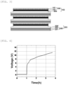
- FIG. 4 is a diagram showing a voltage graph in accordance with time during charge and discharge, and through FIG. 4 , about 11.4 V of full charge voltage was shown, and it can be confirmed that three unit cells having a degree of 3.8 V were normally connected in series.
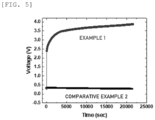
- FIG. 5 is a diagram showing a voltage graph in accordance with time during charge and discharge, and through FIG. 5 , it can be confirmed that normal charge was achieved until 3.8 V.
- a bipolar all-solid battery was manufactured using the solid electrolyte-positive electrode composite and the solid electrolyte-negative electrode composite manufactured in Comparative Example 2 and charged, but the complete curing of a polymer electrolyte was not achieved due to the use of a monomer having a long chain type, including less than three acrylate groups, and it can be confirmed that partial short of a positive electrode and a negative electrode occurred, and normal charge was not achieved.
Landscapes
- Chemical & Material Sciences (AREA)
- General Chemical & Material Sciences (AREA)
- Chemical Kinetics & Catalysis (AREA)
- Electrochemistry (AREA)
- Engineering & Computer Science (AREA)
- Manufacturing & Machinery (AREA)
- Inorganic Chemistry (AREA)
- Materials Engineering (AREA)
- Crystallography & Structural Chemistry (AREA)
- Physics & Mathematics (AREA)
- Condensed Matter Physics & Semiconductors (AREA)
- Dispersion Chemistry (AREA)
- General Physics & Mathematics (AREA)
- Secondary Cells (AREA)
Abstract
Description
- This application claims priority from
Korean Patent Application Nos. 10-2022-0101638, filed on August 12, 2022 10-2023-0105636, filed on August 11, 2023, in the Korean - The present invention relates to a solid electrolyte-electrode composite, a method for manufacturing the solid electrolyte-electrode composite and an all-solid battery comprising the solid electrolyte-electrode composite.
- Lithium secondary batteries can be miniaturized and have high energy density and working voltage, and accordingly, are applied in various fields such as mobile devices, electronic products and electric vehicles. As the applications of lithium secondary batteries become more diverse, the required conditions of physical properties increase gradually, particularly, the development on lithium secondary batteries which are stably operated in diverse environments is being required.
- Generally, secondary batteries are manufactured by installing an electrode assembly composed of a negative electrode, a positive electrode and a separator in a case having a certain space of a cylindrical, a prismatic, or a pouch type.
- As the conventional electrolyte for electrochemical devices, a liquid type electrolyte in which a salt is dissolved in a non-aqueous organic solvent has been widely used. However, the liquid electrolyte induces the deterioration of an electrode material, has strong possibility of volatilizing an organic solvent, produces combustion or the like due to the elevation of the temperature, and has concerns on leakage, and there are difficulties in accomplishing electrochemical devices of diverse types, which require safety.
- Accordingly, studies on an all-solid battery in which a solid electrolyte having high electrochemical stability in contrast to a liquid electrolyte, are being actively conducted. However, there are limitations in accomplishing complete curing to an electrolyte solution present in an electrode when performing curing for preparing a solid electrolyte.
- The present invention is to solve the above-described defects and to provide a solid electrolyte-electrode composite in which complete curing is achieved, and an unreacted monomer is not detected.
- In addition, there is provided a method for manufacturing a solid electrolyte-electrode composite having an increased curing degree of an electrolyte by performing both photocuring and thermal curing.
- In addition, there is provided an all-solid battery comprising the solid electrolyte-electrode composite.
- According to an embodiment, the present invention provides a solid electrolyte-electrode composite, which does not show a peak in a wavenumber region of 1,700 cm-1 to 1,600 cm-1by Fourier-Transform Infrared Spectroscopic analysis.
- In addition, the present invention provides a method for preparing a solid electrolyte-electrode composite, comprising: immersing an electrode in an electrolyte precursor composition comprising a photo-crosslinkable monomer comprising three or more acrylate groups, an initiator, a lithium salt and an organic solvent; photocuring the electrode immersed in the electrolyte precursor composition to form a polymer electrolyte membrane; and thermal curing the electrode at which the polymer electrolyte membrane is formed.
- In addition, the present invention provides an all-solid battery comprising the solid electrolyte-electrode composite.
- The solid electrolyte-electrode composite according to the present invention includes a rigid polymer electrolyte membrane in which complete polymerization is achieved without an unreacted monomer, and defects arising short due to the leakage of an electrolyte solution from an electrode may be prevented, and thus, the charge performance of a battery may be improved.
- Meanwhile, the method for preparing the solid electrolyte-electrode composite according to the present invention uses a material including three or more acrylate groups to increase crosslinking density and achieve complete polymerization through photocuring and thermal curing, and accordingly, an electrolyte precursor solution may be completely cured without remaining the electrolyte precursor solution in the electrolyte as well as at the surface of the electrode, thereby showing excellent processability and safety.
- Ultimately, there are advantages in the present invention of providing a battery having improved safety in diverse driving environment.
-
-
FIG. 1 is a diagram showing the FTIR spectrums of solid electrolyte-electrode composites prepared in Example 1 and Comparative Example 1. -
FIG. 2 is a diagram showing the FTIR spectrum of a solid electrolyte-electrode composite prepared in Comparative Example 2. -
FIG. 3 is a diagram showing the configuration of an all-solid battery according to an exemplary embodiment of the present invention. -
FIG. 4 is a diagram showing the charge and discharge profile of an all-solid battery manufactured according to Example 1. -
FIG. 5 is a diagram showing the charge and discharge profiles of all-solid batteries manufactured according to Example 1 and Comparative Example 2. -
- 100: positive electrode
- 101: positive electrode current collector
- 102: positive electrode active material layer
- 103: solid electrolyte-positive electrode composite
- 200: negative electrode
- 201: negative electrode current collector
- 202: negative electrode active material layer
- 203: solid electrolyte-negative electrode composite
- 300, 300': solid electrolytes
- Hereinafter, the present invention will be explained in more detail.
- First, the solid electrolyte-electrode composite of the present invention will be explained.
- The solid electrolyte-electrode composite according to the present invention may not show a peak in a wavenumber region of 1,700 cm-1 to 1,600 cm-1 when conducting Fourier-Transform Infrared Spectroscopic (FTIR) analysis. The peak observed in the wavenumber region of 1,700 cm-1 to 1,600 cm-1 of FTIR spectrum is shown by C=C stretching vibration and means the remaining of unreacted monomers uncured in an electrode. However, the solid electrolyte-electrode composite according to the present invention is polymerized by 100% without remaining monomers, and there is no peak in the wavenumber region of 1,700 cm-1 to 1,600 cm-1.
- Meanwhile, the phrase "a peak is not shown"means that "a peak is not observed on the spectrum by the naked eye", for example, the transmittance change per 10 cm-1wavenumber is less than 10%.
- In this case, the solid electrolyte-electrode composite means a state of forming a crosslinking structure through the curing of an electrolyte precursor composition soaked into an electrode. In this case, a solid electrolyte may be a gel state or a completely solidified state.
- In an embodiment of the present invention, the thickness of the solid electrolyte-electrode composite may be in a range of 60 µm to 200 µm, preferably, 80 µm to 200 µm, more preferably, 100 µm to 200 µm.
- Meanwhile, in the solid electrolyte-electrode composite, the electrode may be a positive electrode or a negative electrode, and the thickness of the electrode may be 50 µm to 150 µm.
- In addition, in the solid electrolyte-electrode composite, the solid electrolyte may play the role of a separator, but a separator may be further included between the positive electrode and the negative electrode as necessary.
- Hereinafter, the positive electrode, the negative electrode and the separator will be explained in more detail.
- The positive electrode includes a positive electrode active material and may be manufactured by coating a positive electrode slurry including a positive electrode active material, a binder, a conductive agent and a solvent on a positive electrode current collector, drying and rolling.
- The positive electrode current collector is not specifically limited as long as it does not induce the chemical change of a battery, and it is conductive, and for example, stainless steel, aluminum, nickel, titanium, baked carbon, or surface-treated aluminum or stainless steel with carbon, nickel, titanium, silver, or the like, may be used.
- As the positive electrode active material, a lithium transition metal oxide may be used, and any one can be used as long as the intercalation and deintercalation of lithium ions during charge and discharge occur smooth, without limitation, and for example, one or more selected from the group consisting of a lithium nickel cobalt-based composite oxide, a lithium manganese-based composite oxide and a lithium iron phosphate-based composite oxide, preferably, a lithium nickel cobalt-based composite oxide, may be used.
- Particularly, the lithium nickel cobalt-based composite oxide may have a composition of Formula 1.
[Formula 1] Li1+x(NiaCobMncMd)O2
- In Formula 1,
- M is one or more selected from the group consisting of W, Cu, Fe, V, Cr, Ti, Zr, Zn, Al, In, Ta, Y, La, Sr, Ga, Sc, Gd, Sm, Ca, Ce, Nb, Mg, B and Mo, and
- 1+x, a, b, c and d are each independently molar ratios of elements, where
- -0.2≤x≤0.2, 0.60≤a<1, 0<b≤0.30, 0<c≤0.30, 0≤d≤0.10, and a+b+c+d = 1.
- The "1+x" is a lithium molar ratio in the lithium nickel cobalt-based composite oxide, and -0.1≤x≤0.2, or 0≤x≤0.2 may be satisfied. If the lithium molar ratio satisfies the above range, the crystal structure of the lithium nickel cobalt-based composite oxide may be formed stably.
- The "a" is the nickel molar ratio in the entire metal excluding lithium in the lithium nickel cobalt-based composite oxide, and 0.70≤a<1, 0.75≤a<1, or 0.80≤a<1 may be satisfied. If the nickel molar ratio satisfies the range, high energy density may be shown, and high capacity may be accomplished.
- The "b"is the cobalt molar ratio in the entire metal excluding lithium in the lithium nickel cobalt-based composite oxide, and 0<b≤0.20, 0<b≤0.15, or 0<b≤0.10 may be satisfied. If the cobalt molar ratio satisfies the range, excellent resistance properties and output properties may be accomplished.
- The "c" is the manganese molar ratio in the entire metal excluding lithium in the lithium nickel cobalt-based composite oxide, and 0<c≤0.20, 0<c≤0.15, or 0<c≤0.10 may be satisfied. If the manganese molar ratio satisfies the range, the structural stability of a positive electrode active material may be excellent.
- In an embodiment of the present invention, the lithium nickel cobalt-based composite oxide may include one or more doping elements selected from the group consisting of W, Cu, Fe, V, Cr, Ti, Zr, Zn, Al, In, Ta, Y, La, Sr, Ga, Sc, Gd, Sm, Ca, Ce, Nb, Mg, B and Mo, preferably, Al as a doping element. In other words, the "d" representing the molar ratio of the doping element in the entire metal excluding lithium in the lithium nickel cobalt-based composite oxide, and 0<d≤0.10, 0<d≤0.08, or 0<d≤0.05 may be satisfied.
- Preferably, "a", "b", "c" and "d" may satisfy 0.70≤a<1, 0<b≤0.2, 0<c≤0.2, 0≤d≤0.1, respectively.
- The lithium manganese-based composite oxide may be one or more selected from the group consisting of LipMn1-qMa qA2, LipMn2O4-rXr, LipMn2-qMa qMb rA4, LipCo1-qMa qA2, LipCo1-qMa qO2-rXr, LipNi1-qMa qO2-rXr, LipNi1-qCoqO2-rXr, LipNi1-q-rCOqMa rAw, LipNi1-q-rCoqMa rO2-wXw, LipNi1-q-rMnqMa rAw and LipNi1-q-rMnqMa rO2-wXw, and in this case, p, q, r and w satisfy 0.9≤p≤1.2, 0≤q≤1, 0≤r≤1, and 0≤w≤2, respectively, Ma and Mb are the same or different and one or more elements selected from the group consisting of Mg, Al, Co, K, Na, Ca, Si, Ti, Sn, V, Ge, Ga, B, As, Zr, Mn, Cr, Fe, Sr, V, and rare earth elements, A is one or more elements selected from the group consisting of O, F, S and P, and X is one or more elements selected from the group consisting of F, S and P.
- The lithium iron phosphate-based composite oxide may be represented by
Formula 2.
[Formula 2] LiFe1-kMc kPO4
- In
Formula 2, - Mc is one or more selected from Ni, Co, Mn, Al, Mg, Y, Zn, In, Ru, Sn, Sb, Ti, Te, Nb, Mo, Cr, Zr, W, Ir and V, and

- Meanwhile, the positive electrode active material may be included in 80 wt% to 99 wt%, particularly, 90 wt% to 99 wt% based on the total weight of the solid content in a positive electrode slurry. In this case, if the amount of the positive electrode active material is less than 80 wt%, energy density may decrease, and capacity may be reduced.
- The binder is a component assisting the bonding of an active material with a conductive agent and with a current collector, and may generally be added in an amount of 1 wt% to 30 wt% based on the total weight of the solid content in the positive electrode slurry. Examples of the binder may include polyvinylidene fluoride, polyvinyl alcohol, carboxymethyl cellulose (CMC), starch, hydroxypropyl cellulose, regenerated cellulose, polyvinylpyrrolidone, polytetrafluoroethylene, polyethylene, polypropylene, an ethylene-propylene-diene monomer, a sulfonated ethylene-propylene-diene monomer, a styrene-butadiene rubber, a fluoro rubber or diverse copolymers thereof.
- In addition, the conductive agent is a material not inducing the chemical change of a battery but imparting conductivity, and may be added in 0.5 wt% to 20 wt% based on the total weight of the solid content of the positive electrode slurry.
- The conductive agent may be selected from: carbon black such as acetylene black, Ketjen black, channel black, furnace black, lamp black, and thermal black; graphite powder such as natural graphite, artificial graphite, carbon nanotubes and graphite; conductive fibers such as carbon fibers and metal fibers; conductive powder such as fluorocarbon powder, aluminum powder and nickel powder; conductive whiskers such as zinc oxide whiskers and potassium titanate whiskers; conductive metal oxide such as titanium oxide; and conductive material such as polyphenylene derivatives.
- In addition, the solvent of the positive electrode slurry may include an organic solvent such as N-methyl-2-pyrrolidone (NMP), and may be used in an amount to achieve a preferable viscosity with the positive electrode active material, the binder and the conductive agent. For example, the solvent may be included such that the concentration of the solid content in the positive electrode slurry including the positive electrode active material, the binder and the conductive agent may be 40 wt% to 90 wt%, preferably, 50 wt% to 80 wt%.
- The negative electrode according to the present invention includes a negative electrode active material, and may be manufactured by coating a negative electrode slurry including a negative electrode active material, a binder, a conductive agent and a solvent on a negative electrode current collector, drying and rolling.
- The negative electrode current collector is not specifically limited as long as it does not induce the chemical change of a battery, and it is highly conductive, and for example, copper, stainless steel, aluminum, nickel, titanium, baked carbon, surface-treated copper or stainless steel with carbon, nickel, titanium, silver, or the like, or an aluminum-cadmium alloy, may be used. In addition, like the positive electrode current collector, the bonding force of the negative electrode active material may be reinforced by forming minute embossing at the surface thereof, and various shapes including a film, a sheet, a foil, a net, a porous body, a foamed body, a non-woven fabric, or the like may be used.
- In addition, the negative electrode active material may use one or more selected from: a carbon-based material which can reversibly intercalate/deintercalated lithium ions; a metal or an alloy of the metal with lithium; a metal composite oxide; a material which can dope or dedope lithium; a lithium metal; and a transition metal oxide, preferably, a carbon-based material.
- As the carbon-based material which can reversibly intercalate/deintercalated lithium ions, carbon-based negative electrode active materials commonly used in lithium ion secondary batteries may be used without specific limitation, typically, crystalline carbon, amorphous carbon or both of them. Examples of the crystalline carbon may include graphite including natural graphite or synthetic graphite of an amorphous, flat, flake, spherical or fibrous type, and examples of amorphous carbon may include soft carbon (baked carbon at a low temperature), hard carbon, mesophase pitch carbide, baked cokes, or the like.
- The metal or the alloy of the metal and lithium may use a metal selected from the group consisting of Cu, Ni, Na, K, Rb, Cs, Fr, Be, Mg, Ca, Sr, Si, Sb, Pb, In, Zn, Ba, Ra, Ge, Al and Sn, or an alloy of the metal and lithium.
- The metal composite oxide may use one or more selected from the group consisting of: PbO, PbO2, Pb2O3, Pb3O4, Sb2O3, Sb2O4, Sb2O5, GeO, GeO2, Bi2O3, Bi2O4, Bi2O5, LixFe2O3 (0≤x≤1), LixWO2 (0≤x≤1) and SnxMe1-xMe'yOz (Me: Mn, Fe, Pb, Ge; Me': Al, B, P, Si, elements in
group 1,group 2 and group 3 in the periodic table, halogen; 0<x≤1; 1≤y≤3; and 1≤z≤8). - As the material which can dope or dedope lithium, Si, SiOx(0<x≤2), an Si-Y alloy (Y is an element selected from the group consisting of an alkali metal, an alkaline earth metal, an element in group 13, an element in
group 14, a transition metal, a rare earth element and combinations thereof, where Si is excluded), Sn, SnO2, Sn-Y (Y is an element selected from the group consisting of an alkali metal, an alkaline earth metal, an element in group 13, an element ingroup 14, a transition metal, a rare earth element and combinations thereof, where Sn is excluded), or the like may be used, and a mixture of at least one thereof with SiO2 may also be used. Element Y may be selected from the group consisting of Mg, Ca, Sr, Ba, Ra, Sc, Y, Ti, Zr, Hf, Rf, V, Nb, Ta, Db(dubnium), Cr, Mo, W, Sg, Tc, Re, Bh, Fe, Pb, Ru, Os, Hs, Rh, Ir, Pd, Pt, Cu, Ag, Au, Zn, Cd, B, Al, Ga, Sn, In, Ge, P, As, Sb, Bi, S, Se, Te, Po, and combinations thereof. - Examples of the transition metal oxide may include lithium-containing titanium composite oxide (LTO), vanadium oxide, lithium vanadium oxide, or the like.
- The negative electrode active material may be included in 80 wt% to 99 wt% based on the total weight of the solid content of the negative electrode slurry.
- The binder is a component assisting the bonding among the conductive agent, the active material and the current collector, and may generally be added in 1 wt% to 30 wt% based on the total weight of the solid content of the negative electrode slurry. Examples of the binder may include polyvinylidene fluoride, polyvinyl alcohol, carboxymethyl cellulose (CMC), starch, hydroxypropyl cellulose, regenerated cellulose, polyvinylpyrrolidone, polytetrafluoroethylene, polyethylene, polypropylene, an ethylene-propylene-diene monomer, a styrene-butadiene rubber, a fluoro rubber, and diverse copolymers thereof.
- The conductive agent is a component to improve the conductivity of the negative electrode active material even further and may be added in 0.5 wt% to 20 wt% based on the total weight of the solid content of the negative electrode slurry. The conductive agent is not specifically limited as long as it does not induce the chemical change of a battery, and is conductive. For example, carbon black such as acetylene black, Ketjen black, channel black, furnace black, lamp black, and thermal black; graphite powder such as natural graphite, artificial graphite, carbon nanotubes and graphite, having very developed crystal structure; conductive fibers such as carbon fibers and metal fibers; conductive powder such as fluorocarbon powder, aluminum powder and nickel powder; conductive whiskers such as zinc oxide whiskers and potassium titanate whiskers; conductive metal oxide such as titanium oxide; and conductive material such as polyphenylene derivatives, may be used.
- The solvent of the negative electrode slurry may include water or an organic solvent such as NMP and alcohols, and may be used in an amount to achieve a preferable viscosity with the negative electrode active material, the binder and the conductive agent. For example, the solvent may be included such that the solid content in the negative electrode slurry including the negative electrode active material, the binder and the conductive agent may become 30 wt% to 80 wt%, preferably, 40 wt% to 70 wt%.
- The separator separates the negative electrode and the positive electrode and provides a movement passage of lithium ions, and separators commonly used in lithium secondary batteries may be used without specific limitation.
- Particularly, as the separator, a porous polymer film, for example: a porous polymer film formed from a polyolefin-based polymer such as an ethylene homopolymer, a propylene homopolymer, an ethylene/butene copolymer, an ethylene/hexene copolymer and an ethylene/mathacrylate copolymer; or a stacked structure of two or more layers thereof, may be used. In addition, a commonly used porous non-woven fabric, for example, a non-woven fabric of a glass fiber having a high melting point, a polyethylene terephthalate fiber, or the like, may be used. In addition, in order to secure heat resistance and mechanical strength, a coated separator including a ceramic component or a polymer material may be used in a single layer or a multilayer structure.
- Meanwhile, the solid electrolyte-electrode composite according to the present invention may be manufactured by, for example, a method for manufacturing a solid electrolyte-electrode composite, which will be explained later.
- Then, a method for manufacturing the solid electrolyte-electrode composite according to the present invention will be explained.
- When manufacturing a solid electrolyte-electrode composite, after applying an electrolyte precursor solution on an electrode, a curing process is carried out for crosslinking and polymerizing a monomer included in the electrolyte precursor solution. In this case, generally, photocuring is performed through UV irradiation, and the curing through UV is easily achieved at the surface of the electrode, but the complete penetration of UV into the electrode is difficult. Accordingly, the electrolyte precursor solution remaining in the electrode may leak out during the processing, and there is possibility that the process itself is impossible.
- Even the curing process is performed through thermal curing, the electrolyte may vaporize due to heat, and it is difficult to form a polymer electrolyte membrane in a film shape at the surface of the electrode, undesirably.
- Accordingly, the inventors of the present application introduces a method of applying photocuring after applying an electrolyte on an electrode to form a polymerized electrolyte membrane on the surface of the electrode, and then applying thermal curing. Since, the polymerized electrolyte membrane is present at the surface, the vaporization or leakage of uncured electrolyte precursor solution during subsequent thermal curing may be prevented. Through this, unreacted monomer may not remain and completely polymerized at the surface of the electrode to the inside of the electrode, and the efficiency and stability of processes may be improved, and an all-solid battery having excellent safety may be provided even under inferior driving environments.
- Hereinafter, each step will be explained in more detail.
- The method for manufacturing the solid electrolyte-electrode composite according to an embodiment of the present invention includes a step of immersing an electrode in an electrolyte precursor solution. For example, a process of applying 10 µl to 100 µl, preferably, 20 µl to 80 µl, more preferably, 30 µl to 70 µl of an electrolyte precursor composition per cm2 on the surface of the electrode through blade coating, and immersing for 10 seconds to 60 seconds in a vacuum state, may be carried out. If the amount of the electrolyte precursor composition is in the range, a polymer electrolyte membrane may be easily formed by UV curing.
- In an embodiment of the present invention, the electrolyte precursor composition includes a photo-crosslinkable monomer, an initiator, a lithium salt and an organic solvent. Hereinafter, the configuration of the electrolyte precursor composition will be explained in more detail.
- The photo-crosslinkable monomer is required to be photo-crosslinkable and thermal-crosslinkable, and include three or more acrylate groups, for example, one or more selected from the group consisting of ethoxylated trimethylolpropane triacrylate (ETPTA), trimethylolpropane ethoxytriacrylate, dipentaerythritolpentaacrylate, dipentaerythritolhexaacrylate and tris(2-hydroxyethyl)isocyanuratetriacrylate, preferably, ethoxylated trimethylolpropane triacrylate (ETPTA).
- Since the photo-crosslinkable monomer includes three or more acrylate groups, crosslinking density is high due to photo-crosslinking and thermal-crosslinking. Accordingly, if the manufacturing method of the present invention is applied, there are advantages in that the degree of polymerization is markedly high in contrast to a photo-crosslinkable monomer in a long chain type such as polypropylene glycol diacrylate, which is used for maximizing the function as a liquid electrolyte mainly by maximally reducing the degree of curing.
- The amount of the photo-crosslinkable monomer may be in a range of 1 wt% to 30 wt%, preferably, 5 wt% to 30 wt%, more preferably, 5 wt% to 25wt% based on the total weight of the electrolyte precursor composition. For the formation of a polymer crosslinking structure, the amount of the photo-crosslinkable monomer may preferably be 1 wt% or more, and for maintaining the ionic conductivity of the electrolyte to a certain degree or more, the amount may preferably be 30 wt% or less.
- The initiator may include a photoinitiator and a thermal initiator, or a photo and thermal dual-responsive initiator.
- The photoinitiator may be a compound that may form radicals by light such as ultraviolet, without specific limitation, and may be, for example, one or more selected from the group consisting of 2-hydroxy-2-methylpropiophenone (HMPP), 1-hydroxy-cyclohexylphenyl-ketone, benzophenone, 2-hydroxy-1-[4-(2-hydroxyethoxy)phenyl]-2-methyl-1-propanone, oxy-phenylacetic acid 2-[2-oxo-2 phenyl-acetoxy-ethoxy]-ethyl ester, oxy-phenyl-acetic acid 2-[2-hydroxyethoxy]-ethyl ester, alpha-dimethoxy-alpha-phenylacetophenone, 2-benzyl-2-(dimethylamino)-1-[4-(4-morpholinyl)phenyl]-1-butanone, 2-methyl-1-[4-(methylthio)phenyl]-2-(4-morpholinyl)-1-propanone, diphenyl (2,4,6-trimethylbenzoyl)-phosphine oxide, bis(2,4,6-trimethyl benzoyl)-phenyl phosphine oxide, bis(eta 5-2,4-cyclopentadien-1-yl), bis[2,6-difluoro-3-(1H-pyrrol-1-yl)phenyl]titanium, 4-isobutylphenyl-4'-methylphenyliodonium, hexafluorophosphate, and methyl benzoylformate, preferably, 2-hydroxy-2-methylpropiophenone (HMPP).
- The thermal initiator may be a compound that may form radicals by heat, without specific limitation, and may be, for example, one or more selected from the group consisting of benzoyl peroxide, acetyl peroxide, dilauryl peroxide, di-tert-butyl peroxide, t-butyl peroxy-2-ethyl-hexanoate, cumyl hydroperoxide, hydrogen peroxide, 2,2'-azobis(2-cyanobutane), 2,2'-azobis(methylbutyronitrile), 2,2'-azobis(isobutyronitrile) (AIBN) and 2,2'-azobisdimethyl-valeronitrile (AMVN), preferably, AIBN.
- The photo and thermal dual-responsive initiator may be a compound that may form radicals by light and heat, without specific limitation.
- The total amount of the initiator may be 0.2 wt% to 5 wt%, preferably, 0.2 wt% to 2 wt%, more preferably, 0.5 wt% to 1.5 wt% based on the total weight of the monomer in the electrolyte precursor composition. Within the range, sufficient curing may be achieved, and an excessive amount of the initiator may not remain.
- The lithium salt may use commonly used ones as an electrolyte for lithium secondary batteries, without limitation, and particularly, the lithium salt may include Li+ as a cation, and one or more anions selected from F-, Cl-, Br-, I-, NO3 -, N(CN)2 -, BF4 -, ClO4 -, B10Cl10 -, AlCl4 -, AlO2 -, PF6 -, CF3SO3 -, CH3CO2 -, CF3CO2 -, AsF6 -, SbF6 -, CH3SO3 -, (CF3CF2SO2)2N-, (CF3SO2)2N-, (FSO2)2N-, BF2C2O4 -, BC4O8 -, BF2C2O4CHF-, PF4C2O4 -, PF2C4O8 -, PO2F2 -, (CF3)2PF4 -, (CF3)3PF3 -, (CF3)4PF2 -, (CF3)5PF-, (CF3)6P-, C4F9SO3 -, CF3CF2SO3 -, CF3CF2(CF3)2CO-, (CF3SO2)2CH-, CF3(CF2)7SO3 - and SCN-.
- Particularly, the lithium salt may be one or more selected from the group consisting of LiPF6, LiClO4, LiBF4, lithium bis (fluorosulfonyl) imide (LiN(FSO2)2; LiFSI), lithium bis(trifluoromethanesulfonyl)imide (LiTFSI), lithium bis(pentafluoroethanesulfonyl)imide (LiBETI), lithium trifluoromethanesulfonate (LiSO3CF3), lithium difluorophosphate (LiPO2F2), lithium bis (oxalato)borate (LiBOB), lithium difluoro(oxalato)borate (LiFOB), lithiumdifluoro(bisoxalato)phosphate (LiDFOP), lithiumtetrafluoro(oxalato)phosphate (LiTFOP), and lithiumfluoromalonato(difluoro)borate(LiFMDFB), preferably, one or more selected from the group consisting of LiPF6, LiClO4 LiBF4, LiFSI and LiTFSI.
- In an embodiment of the present invention, the concentration of the lithium salt in the electrolyte precursor composition may be 0.5 M to 4.0 M, preferably, 0.8 M to 2.0 M.
- In view of improving the ionic conductivity, the concentration of the lithium salt may preferably be 0.5 M or more, but if the concentration is greater than 4.0 M, the salt may inhibit the polymerization of the photo-crosslinkable monomer.
- As the organic solvent of the electrolyte precursor composition, one or more selected from the group consisting of ethylene carbonate (EC), propylene carbonate (PC), fluorinated ethylene carbonate (FEC), diethyl carbonate (DEC), G-butyrolactone (GBL), sulfolane (SL), and succinonitrile (SN), may be used. Since the present invention includes a thermal curing step, the organic solvent is required to have a boiling point greater than the temperature for carrying out the thermal curing. For example, if the thermal curing is carried out at 80°C, the boiling point of the organic solvent may be greater than 80°C.
- Other constituent components excluding the organic solvent among the total weight of the electrolyte precursor composition, for example, the residue excluding the amounts of the photo-crosslinkable monomer, the initiator, the lithium salt and additives, may be all the organic solvent, unless otherwise referred to.
- The electrolyte precursor composition according to the present invention may further include one or more additives selected from the group consisting of a cyclic carbonate-based compound, a sultone-based compound, a sulfate-based compound, a phosphor-based compound, a nitrile-based compound, an amine-based compound, a silane-based compound, a benzene-based compound, and a lithium salt-based compound.
- The cyclic carbonate-based compound may be one or more selected from the group consisting of vinylene carbonate (VC), vinyl ethylene carbonate (VEC) and fluoroethylene carbonate (FEC), particularly, vinylene carbonate.
- The sultone-based compound may be a material forming a stable SEI membrane by a reduction reaction at the surface of a negative electrode, and may be one or more selected from the group consisting of 1,3-propane sultone (PS), 1,4-butane sultone, ethene sultone, prop-1-en-1,3-sultone (PRS), 1,4-butene sultone and 1-methyl-1,3-propene sultone, particularly, 1,3-propane sultone (PS) or prop-1-en-1,3-sultone (PRS).
- The sulfate-based compound may be a material forming a stable SEI membrane which may not be electrically decomposed at the surface of the negative electrode to make cracks even stored at a high temperature, and may be one or more selected from the group consisting of ethylene sulfate (Esa), trimethylene sulfate (TMS), and methyl trimethylene sulfate (MTMS).
- The phosphor-based compound may be a phosphate-based or a phosphite-based compound, particularly, one or more selected from the group consisting of tris(trimethyl silyl)phosphate, tris(trimethyl silyl)phosphite, tris(2,2,2-trifluoroethyl)phosphate and tris(trifluoroethyl)phosphite.
- The nitrile-based compound may be one or more selected from the group consisting of succinonitrile (SN), adiponitrile (ADN), acetonitrile, propionitrile, butyronitrile, valeronitrile, caprylonitrile, heptanenitrile, cyclopentane carbonitrile, cyclohexane carbonitrile, 2-fluorobenzonitrile, 4-fluorobenzonitrile, difluorobenzonitrile, trifluorobenzonitrile, phenylacetonitrile, 2-fluorophenylacetonitrile, 4-fluorophenylacetonitrile, ethylene glycol bis(2-cyanoethyl) ether (ASA3), 1,3,5-hexane tricarbonitrile (HTCN), 1,4-dicyano 2-butene (DCB) and 1,2,3-tris(2-cyanoethyl)propane (TCEP).
- The amine-based compound may be one or more selected from the group consisting of triethanolamine and ethylenediamine, and the silane-based compound may be tetravinylsilane.
- The benzene-based compound may be one or more selected from the group consisting of monofluorobenzene, difluorobenzene, trifluorobenzene and tetrafluorobenzene.
- The lithium salt-based compound is a compound different from the lithium salt included in the non-aqueous electrolyte, and may be one or more selected from the group consisting of lithium difluoro phosphate (LiDFP; LiPO2F2), lithium bisoxalatoborate (LiBOB; LiB(C2O4)2), lithium tetrafluoroborate (LiBF4), lithium tetraphenylborate, lithium difluoro(oxalato)borate (LiDFOB) and lithium difluoro(bisoxalato)phosphate (LiDFOP).
- Preferably, the electrolyte precursor composition may further include one or more additives selected from the group consisting of vinylene carbonate (VC), 1,3-propane sultone (PS), and ethylene sulfate (Esa), and may be included in the electrolyte precursor composition in 0.5 wt% to 5 wt% based on the total weight of the electrolyte precursor composition.
- Meanwhile, in an embodiment of the present invention, the electrolyte precursor composition may have a viscosity at 25°C of 20 cP or less, preferably, 10 cP to 20 cP, more preferably, 10 cP to 15 cP, and the viscosity may be achieved by controlling the amount of the lithium salt. If the viscosity of the precursor composition is 20 cP or less, the degree of immersion of the electrode in the electrolyte precursor composition may be suitably secured, and battery capacity expression may be favorable.
- The method for manufacturing the solid electrolyte-electrode composite according to an embodiment of the present invention includes a step of photocuring the electrode immersed in the electrolyte precursor composition to form a polymer electrolyte membrane, and particularly, the photocuring may be carried out by irradiating ultraviolet with an intensity of 20 mW/cm2 to 200 mW/cm2, preferably, 80 mW/cm2 to 190 mW/cm2, more preferably, 100 mW/cm2 to 180 mW/cm2, for 20 seconds to 120 seconds.
- The photo-crosslinkable monomer may be crosslinked from each other by the irradiation of ultraviolet to form a polymer matrix which is a three-dimensional network structure, and accordingly, a polymer electrolyte membrane may be formed on the surface of the electrode.
- After the step of photocuring, the thickness of the polymer electrolyte membrane may be 10 µm to 50 µm, preferably, 15 µm to 45 µm, more preferably, 20 µm to 40 µm. After performing a thermal curing step, the thickness of the polymer electrolyte membrane is not changed.
- The method for manufacturing the solid electrolyte-electrode composite according to an embodiment of the present invention includes a step of thermal curing the photocured electrode, particularly, storing the photocured electrode in an oven set to 60°C to 90°C, particularly, 60°C to 85°C, more particularly, 70°C to 80°C for 3 hours to 10 hours.
- The electrolyte precursor composition not polymerized and remaining in the electrode after the photocuring may be completely polymerized by the thermal curing.
- Meanwhile, the thickness of the electrode may be 50 µm to 150 µm. If only photocuring is carried out as in the conventional technique, ultraviolet was difficult to penetrate into an electrode having a thickness of 50 µm or more, and complete curing was difficult, but according to the present invention, since both photocuring and thermal curing are applied, complete curing, that is, 100% polymerization without remaining a monomer may be possible even with the thickness.
- After the step of thermal curing, the thickness of the composite of the solid electrolyte and the electrode may be 60 µm to 200 µm, preferably, 80 µm to 200 µm, more preferably, 100 µm to 200 µm. The thickness may be measured using a thickness gauge.
- Then, the all-solid battery according to the present invention will be explained.
- The all-solid battery according to the present invention includes the solid electrolyte-electrode composite.
- Particularly, the solid electrolyte-electrode composite includes one or more solid electrolyte-positive electrode composites and solid electrolyte-negative electrode composites each, and the solid electrolyte-positive electrode composites and the solid electrolyte-negative electrode composites may be alternately stacked.
- For example, as in
FIG. 3 , the all-solid battery may be a bipolar cell in which multiple solid electrolyte-positive electrode composites and solid electrolyte-negative electrode composites are alternately stacked. The solid electrolyte-positive electrode composite 103 is a composited one of apositive electrode 100 including a positive electrodecurrent collector 101 and a positive electrode active material layer 102, formed on the positive electrode current collector, with a solid electrolyte 300. Meanwhile, the solid electrolyte-negative electrode composite 203 is a composited one of a negative electrode 200 including a negative electrode current collector 201 and a negative electrode active material layer 202, formed on the negative electrode current collector, with a solid electrolyte 300'. In this case, the "composite" and "composited" mean a state in which the electrode is immersed in the electrolyte precursor composition, and undergone photocuring and thermal curing to induce the polymerization of the electrolyte at the inside and on surface of the electrode. - The solid electrolyte-electrode composite according to the present invention is a completely cured state as described above, and there are advantages of accomplishing the bipolar cell.
- Meanwhile, the all-solid battery may be manufactured by, for example, a method of forming the solid electrolyte-electrode composite according to the above-described preparation method and then, stacking a counter electrode. Particularly, the all-solid battery may be manufactured by stacking the composite of a solid electrolyte and a positive electrode with a negative electrode, by stacking the composite of a solid electrolyte and a negative electrode with a positive electrode, or by stacking the composite of a solid electrolyte and a positive electrode with the composite of a solid electrolyte and a negative electrode.
- The all-solid battery manufactured according to the present invention may be used as a unit cell in a medium- and large-size battery module including multiple battery cells as well as in a battery cell used as a power source in a small-sized device.
- Hereinafter, the present invention will be explained in particular through particular examples.
- To a mixture solvent of ethylene carbonate (EC) and propylene carbonate (PC) in a weight ratio of 5:5, LiPF6, 10 wt% of ETPTA, 0.5 wt% of AIBN and 0.5 wt% of HMPP were added and mixed to prepare an electrolyte precursor composition. In this case, LiPF6 was controlled to achieve a concentration of 1 M. Then, the viscosity of the prepared composition was measured under conditions of a temperature of 25°C, a humidity of 50 RH% and a frequency of 30 Hz, using a Brookfield viscometer (DV-II+ PRO Viscometer, Brookfield Co.), and the result was 15 cP.
- To N-methyl-2-pyrrolidone (NMP), Li(Ni0.8Co0.1Mn0.1)O2 as a positive electrode active material, a conductive agent (carbon black) and a binder (polyvinylidene fluoride) were added in a weight ratio of 97.5:1:1.5 to prepare a positive electrode slurry (solid content: 60 wt%). The positive electrode slurry was applied on an aluminum (Al) thin film, which was a positive electrode current collector with a thickness of 15 µm, and dried, and then, roll pressing was performed to form a positive electrode having a thickness of 100 µm.
- Graphite as a negative electrode active material, SBR-CMC as a binder and carbon black as a conductive agent were added in a weight ratio of 95:3.5:1.5 to water as a solvent, to prepare a negative electrode slurry (solid content: 60 wt%). The negative electrode slurry was applied on a copper (Cu) thin film, which is a negative electrode current collector having a thickness of 10 µm and dried, and then, roll pressing was performed to form a negative electrode having a thickness of 140 µm.
- On each of the positive electrode and the negative electrode, 50 µl per cm2 of the electrolyte precursor composition was applied through doctor blading, and UV of 150 mW/cm2 was irradiated for 30 seconds to carry out photocuring. Then, an electrode including a polymer electrode membrane of which surface was photocured, was moved into an oven and undergone thermal curing by storing at 80°C for 4 hours.
- The thicknesses of the composites of the solid electrolytes and the electrodes completed were confirmed suing a thickness gauge, and the solid electrolyte-positive electrode was 130 µm, and the solid electrolyte-negative electrode composite was 170 µm.
- Polymer electrolytes were formed on the surfaces of a positive electrode and a negative electrode by the same process as in Example 1, except for not carrying out thermal curing in (4) of Example 1.
- Polymer electrolytes were formed on the surfaces of a positive electrode and a negative electrode by the same process as in Example 1, except for using polypropylene glycol diacrylate instead of ETPTA in (1) of Example 1.
- With respect to the solid electrolyte-positive electrode composites manufactured in Example 1, Comparative Example 1 and Comparative Example 2, FTIR spectrums as in
FIG. 1 and FIG. 2 were obtained through FTIR analysis. FTIR analysis was conducted using Nicolet 6700 FTIR System and SMART Orbit ATR Accessory(ZnSe) of Thermo Fisher Scientic Co., with resolution conditions of 1 cm-1 in a region of 1,700-1 to 1,600cm-1. - In
FIG. 1 , in Example 1, a sharp shape is shown without a peak in a wave number region of 1,700-1,600 cm-1, but in Comparative Example 1, many peaks are observed. In addition, inFIG. 2 , it can be confirmed that many peaks are also shown in Comparative Example 2. Through the results, it can be confirmed that uncured monomer remained in the electrodes of Comparative Examples 1 and 2, but uncured monomer did not remain in the electrode of Example 1. - By alternately stacking the solid electrolyte-positive electrode composite and the solid electrolyte-negative electrode composite manufactured in Example 1 three times, as in
FIG. 3 , a bipolar all-solid battery with three stacked unit cells was manufactured. - With respect to the all-solid battery manufactured, constant-current charge was conducted at 25°C with a current of 0.1 C until reaching 11.4 V. A charge-completed cell underwent a break time for about 60 seconds and the retaining of the voltage was confirmed.
FIG. 4 is a diagram showing a voltage graph in accordance with time during charge and discharge, and throughFIG. 4 , about 11.4 V of full charge voltage was shown, and it can be confirmed that three unit cells having a degree of 3.8 V were normally connected in series. - The same bipolar all-solid battery was manufactured in Comparative Example 1, but the polymer electrolyte was incompletely cured, and the electrolyte leaked out from the electrode to arise short, and a normal bipolar all-solid battery could not be accomplished.
- By stacking the solid electrolyte-positive electrode composite and the solid electrolyte-negative electrode composite manufactured in Example 1, a bipolar all-solid battery composed of one unit cell was manufactured.
- With respect to the all-solid battery manufactured, constant-current charge was conducted at 25°C with a current of 0.1 C until reaching 3.8 V. A charge-completed cell underwent a break time for about 60 seconds and the retaining of the voltage was confirmed.
FIG. 5 is a diagram showing a voltage graph in accordance with time during charge and discharge, and throughFIG. 5 , it can be confirmed that normal charge was achieved until 3.8 V. - By the same method, a bipolar all-solid battery was manufactured using the solid electrolyte-positive electrode composite and the solid electrolyte-negative electrode composite manufactured in Comparative Example 2 and charged, but the complete curing of a polymer electrolyte was not achieved due to the use of a monomer having a long chain type, including less than three acrylate groups, and it can be confirmed that partial short of a positive electrode and a negative electrode occurred, and normal charge was not achieved.
Claims (13)
- A solid electrolyte-electrode composite, not showing a peak in a wave number region of 1,700 cm-1 to 1,600 cm-1by Fourier Transform Infrared Spectroscopic analysis.
- The solid electrolyte-electrode composite of claim 1, wherein a thickness of the solid electrolyte-electrode composite is in a range of 60 µm to 200 µm.
- The solid electrolyte-electrode composite of claim 1, whereinthe electrode is a positive electrode comprising a positive electrode active material, andthe positive electrode active material comprises one or more selected from the group consisting of a lithium nickel cobalt-based composite oxide, a lithium manganese-based composite oxide and a lithium iron phosphate-based composite oxide.
- The solid electrolyte-electrode composite of claim 3, whereinthe positive electrode active material comprises the lithium nickel cobalt-based composite oxide, andthe lithium nickel cobalt-based composite oxide has a composition of the following Formula 1:
[Formula 1] Li1+x(NiaCobMncMd)O2
in Formula 1,M is one or more selected from the group consisting of W, Cu, Fe, V, Cr, Ti, Zr, Zn, Al, In, Ta, Y, La, Sr, Ga, Sc, Gd, Sm, Ca, Ce, Nb, Mg, B and Mo, and1+x, a, b, c and d are each independently molar ratios of elements, where-0.2≤x≤0.2, 0.60≤a<1, 0<b≤0.30, 0<c≤0.30, 0≤d≤0.10, and a+b+c+d = 1. - The solid electrolyte-electrode composite of claim 1, whereinthe electrode is a negative electrode comprising a negative electrode active material, andthe negative electrode active material is a carbon-based material.
- A method for manufacturing a solid electrolyte-electrode composite, comprising:immersing an electrode in an electrolyte precursor composition comprising a photo-crosslinkable monomer comprising three or more acrylate groups, an initiator, a lithium salt and an organic solvent;photocuring the electrode immersed in the electrolyte precursor composition to form a polymer electrolyte membrane; andthermal curing the electrode at which the polymer electrolyte membrane is formed.
- The method of claim 6, wherein the photo-crosslinkable monomer is one or more selected from the group consisting of ethoxylated trimethylolpropane triacrylate, trimethylolpropane ethoxytriacrylate, dipentaerythritolpentaacrylate, dipentaerythritolhexaacrylate and tris(2-hydroxyethyl)isocyanuratetriacrylate.
- The method of claim 6, wherein the initiator comprises a photoinitiator and a thermal initiator, or a photo and thermal dual-responsive initiator.
- The method of claim 6, wherein the electrolyte precursor composition has a viscosity of 20 cP or less.
- The method of claim 6, wherein the amount of the photo-crosslinkable monomer is in a range of 1 wt% to 30 wt% based on the total weight of the electrolyte precursor composition.
- The method of claim 6, wherein the thermal curing is carried out by storing the photocured electrode at 60°C to 90°C for 3 hours to 10 hours.
- The method of claim 6, wherein the organic solvent has a boiling point which is higher than the temperature carrying out the thermal curing.
- An all-solid battery comprising the solid electrolyte-electrode composite of claim 1.
Applications Claiming Priority (2)
| Application Number | Priority Date | Filing Date | Title |
|---|---|---|---|
| KR20220101638 | 2022-08-12 | ||
| PCT/KR2023/012002 WO2024035232A1 (en) | 2022-08-12 | 2023-08-11 | Solid electrolyte-electrode composite, method for manufacturing solid electrolyte-electrode composite, and all-solid-state battery comprising same solid electrolyte-electrode composite |
Publications (2)
| Publication Number | Publication Date |
|---|---|
| EP4571916A1 true EP4571916A1 (en) | 2025-06-18 |
| EP4571916A4 EP4571916A4 (en) | 2026-01-07 |
Family
ID=90052719
Family Applications (1)
| Application Number | Title | Priority Date | Filing Date |
|---|---|---|---|
| EP23853097.6A Pending EP4571916A4 (en) | 2022-08-12 | 2023-08-11 | Solid electrolyte-electrode compound, method for producing the solid electrolyte-electrode compound and solid battery with this solid electrolyte-electrode compound |
Country Status (3)
| Country | Link |
|---|---|
| EP (1) | EP4571916A4 (en) |
| KR (1) | KR20240023376A (en) |
| CN (1) | CN119585902A (en) |
Family Cites Families (5)
| Publication number | Priority date | Publication date | Assignee | Title |
|---|---|---|---|---|
| JP2002025559A (en) * | 2000-07-03 | 2002-01-25 | Sony Corp | Battery |
| US7422826B2 (en) * | 2004-04-07 | 2008-09-09 | Greatbatch Ltd. | In situ thermal polymerization method for making gel polymer lithium ion rechargeable electrochemical cells |
| US20050271939A1 (en) * | 2004-06-07 | 2005-12-08 | Yang Xu | Novel polymer electrolyte for electrochemical power sources |
| JPWO2011024789A1 (en) * | 2009-08-24 | 2013-01-31 | Jsr株式会社 | Electrode forming composition, electrode forming slurry, electrode and electrochemical device |
| KR20210074811A (en) | 2019-12-12 | 2021-06-22 | 한국에너지기술연구원 | Composite Electrode for All-Solid-State Battery and Method Of Manufacturing The Same |
-
2023
- 2023-08-11 KR KR1020230105636A patent/KR20240023376A/en active Pending
- 2023-08-11 CN CN202380055411.8A patent/CN119585902A/en active Pending
- 2023-08-11 EP EP23853097.6A patent/EP4571916A4/en active Pending
Also Published As
| Publication number | Publication date |
|---|---|
| KR20240023376A (en) | 2024-02-21 |
| CN119585902A (en) | 2025-03-07 |
| EP4571916A4 (en) | 2026-01-07 |
Similar Documents
| Publication | Publication Date | Title |
|---|---|---|
| KR102102985B1 (en) | Electrolyte for lithium secondary battery and lithium secondary battery comprising the same | |
| JP7055479B2 (en) | A lithium secondary battery containing a composition for a gel polymer electrolyte and a gel polymer electrolyte formed from the composition. | |
| KR102828355B1 (en) | Copolymer for polymer electrolyte, gel polymer electrolyte comprising the same and lithium secondary battery | |
| US11646442B2 (en) | Electrolyte for lithium secondary battery and lithium secondary battery including same | |
| KR20190050709A (en) | Electrolyte for lithium secondary battery and lithium secondary battery comprising the same | |
| KR102828354B1 (en) | Copolymer for polymer electrolyte, gel polymer electrolyte comprising the same and lithium secondary battery | |
| KR101545432B1 (en) | Lithium secondary battery | |
| US11114698B2 (en) | Method of preparing pouch type secondary battery | |
| JP2022536290A (en) | In-situ polymerized polymer electrolyte for lithium-ion batteries | |
| KR102544264B1 (en) | Polymer for electrolyte, electrolyte composition comprising the same and gel polymer electrolyte formed therefrom | |
| KR20180083273A (en) | Composition for gel polymer electrolyte and lithium secondary battery comprising the same | |
| JP7442660B2 (en) | Method for producing a gel polymer electrolyte secondary battery, and a gel polymer electrolyte secondary battery produced thereby | |
| CN120073061B (en) | High-entropy solid polymer electrolyte, preparation method thereof and solid battery | |
| CN111052482A (en) | Composition for gel polymer electrolyte, gel polymer electrolyte prepared from the composition, and lithium secondary battery comprising the gel polymer electrolyte | |
| KR20190064260A (en) | Composition for gel polymer electrolyte, gel polymer electrolyte and lithium secondary battery comprising the same | |
| US20260058136A1 (en) | Solid electrolyte-electrode composite, method for manufacturing the solid electrolyte-electrode composite and all-solid battery comprising the solid-electrolyte-electrode composite | |
| KR102846664B1 (en) | Composition for electrolyte of lithium secondary battery, gel polymer electrolyte and lithium secondary battery comprising the same | |
| KR102846663B1 (en) | Composition for electrolyte of lithium secondary battery, gel polymer electrolyte and lithium secondary battery comprising the same | |
| US20220037695A1 (en) | Composition for polymer electrolyte and lithium secondary battery including polymer electrolyte prepared therefrom | |
| KR102465821B1 (en) | Composition for polymer electrolyte and lithium secondary battery comprising the polymer electrolyte formed therefrom | |
| CN111033861A (en) | Composition for gel polymer electrolyte, gel polymer electrolyte prepared from the composition, and lithium secondary battery including the gel polymer electrolyte | |
| KR20240023376A (en) | Solid electrolyte-electrode composite, method for preparing solid electrolyte-electrode composite and solid state battery comprising the solid electrolyte-electrode composite | |
| KR102803272B1 (en) | A precursor composition for manufacturing polymer electrolyte, a polymer electrolyte manufactured by using the same and a secondary battery | |
| US20250062416A1 (en) | Method for Manufacturing Secondary Battery | |
| EP4668404A1 (en) | Lithium secondary battery with improved safety |
Legal Events
| Date | Code | Title | Description |
|---|---|---|---|
| STAA | Information on the status of an ep patent application or granted ep patent |
Free format text: STATUS: THE INTERNATIONAL PUBLICATION HAS BEEN MADE |
|
| PUAI | Public reference made under article 153(3) epc to a published international application that has entered the european phase |
Free format text: ORIGINAL CODE: 0009012 |
|
| STAA | Information on the status of an ep patent application or granted ep patent |
Free format text: STATUS: REQUEST FOR EXAMINATION WAS MADE |
|
| 17P | Request for examination filed |
Effective date: 20250117 |
|
| AK | Designated contracting states |
Kind code of ref document: A1 Designated state(s): AL AT BE BG CH CY CZ DE DK EE ES FI FR GB GR HR HU IE IS IT LI LT LU LV MC ME MK MT NL NO PL PT RO RS SE SI SK SM TR |
|
| DAV | Request for validation of the european patent (deleted) | ||
| DAX | Request for extension of the european patent (deleted) | ||
| A4 | Supplementary search report drawn up and despatched |
Effective date: 20251208 |
|
| RIC1 | Information provided on ipc code assigned before grant |
Ipc: H01M 10/0565 20100101AFI20251202BHEP Ipc: H01M 10/42 20060101ALI20251202BHEP Ipc: H01M 10/0585 20100101ALI20251202BHEP Ipc: H01M 4/1391 20100101ALI20251202BHEP Ipc: H01M 4/1393 20100101ALI20251202BHEP Ipc: H01M 10/0525 20100101ALI20251202BHEP Ipc: H01M 4/525 20100101ALI20251202BHEP Ipc: H01M 4/505 20100101ALI20251202BHEP Ipc: H01M 4/131 20100101ALI20251202BHEP Ipc: H01M 4/133 20100101ALI20251202BHEP Ipc: H01M 4/58 20100101ALI20251202BHEP Ipc: H01M 4/62 20060101ALI20251202BHEP Ipc: H01M 10/052 20100101ALI20251202BHEP |