EP4571682A1 - Electronic device - Google Patents
Electronic device Download PDFInfo
- Publication number
- EP4571682A1 EP4571682A1 EP23851719.7A EP23851719A EP4571682A1 EP 4571682 A1 EP4571682 A1 EP 4571682A1 EP 23851719 A EP23851719 A EP 23851719A EP 4571682 A1 EP4571682 A1 EP 4571682A1
- Authority
- EP
- European Patent Office
- Prior art keywords
- light
- display
- electronic device
- housing
- baffle
- Prior art date
- Legal status (The legal status is an assumption and is not a legal conclusion. Google has not performed a legal analysis and makes no representation as to the accuracy of the status listed.)
- Pending
Links
Images






Classifications
-
- G—PHYSICS
- G06—COMPUTING OR CALCULATING; COUNTING
- G06V—IMAGE OR VIDEO RECOGNITION OR UNDERSTANDING
- G06V40/00—Recognition of biometric, human-related or animal-related patterns in image or video data
- G06V40/10—Human or animal bodies, e.g. vehicle occupants or pedestrians; Body parts, e.g. hands
- G06V40/12—Fingerprints or palmprints
-
- G—PHYSICS
- G06—COMPUTING OR CALCULATING; COUNTING
- G06F—ELECTRIC DIGITAL DATA PROCESSING
- G06F1/00—Details not covered by groups G06F3/00 - G06F13/00 and G06F21/00
- G06F1/16—Constructional details or arrangements
-
- G—PHYSICS
- G06—COMPUTING OR CALCULATING; COUNTING
- G06F—ELECTRIC DIGITAL DATA PROCESSING
- G06F1/00—Details not covered by groups G06F3/00 - G06F13/00 and G06F21/00
- G06F1/16—Constructional details or arrangements
- G06F1/1601—Constructional details related to the housing of computer displays, e.g. of CRT monitors, of flat displays
- G06F1/1605—Multimedia displays, e.g. with integrated or attached speakers, cameras, microphones
-
- G—PHYSICS
- G06—COMPUTING OR CALCULATING; COUNTING
- G06F—ELECTRIC DIGITAL DATA PROCESSING
- G06F1/00—Details not covered by groups G06F3/00 - G06F13/00 and G06F21/00
- G06F1/16—Constructional details or arrangements
- G06F1/1613—Constructional details or arrangements for portable computers
- G06F1/1615—Constructional details or arrangements for portable computers with several enclosures having relative motions, each enclosure supporting at least one I/O or computing function
- G06F1/1616—Constructional details or arrangements for portable computers with several enclosures having relative motions, each enclosure supporting at least one I/O or computing function with folding flat displays, e.g. laptop computers or notebooks having a clamshell configuration, with body parts pivoting to an open position around an axis parallel to the plane they define in closed position
-
- G—PHYSICS
- G06—COMPUTING OR CALCULATING; COUNTING
- G06F—ELECTRIC DIGITAL DATA PROCESSING
- G06F1/00—Details not covered by groups G06F3/00 - G06F13/00 and G06F21/00
- G06F1/16—Constructional details or arrangements
- G06F1/1613—Constructional details or arrangements for portable computers
- G06F1/1633—Constructional details or arrangements of portable computers not specific to the type of enclosures covered by groups G06F1/1615 - G06F1/1626
- G06F1/1637—Details related to the display arrangement, including those related to the mounting of the display in the housing
- G06F1/1641—Details related to the display arrangement, including those related to the mounting of the display in the housing the display being formed by a plurality of foldable display components
-
- G—PHYSICS
- G06—COMPUTING OR CALCULATING; COUNTING
- G06F—ELECTRIC DIGITAL DATA PROCESSING
- G06F1/00—Details not covered by groups G06F3/00 - G06F13/00 and G06F21/00
- G06F1/16—Constructional details or arrangements
- G06F1/1613—Constructional details or arrangements for portable computers
- G06F1/1633—Constructional details or arrangements of portable computers not specific to the type of enclosures covered by groups G06F1/1615 - G06F1/1626
- G06F1/1637—Details related to the display arrangement, including those related to the mounting of the display in the housing
- G06F1/1652—Details related to the display arrangement, including those related to the mounting of the display in the housing the display being flexible, e.g. mimicking a sheet of paper, or rollable
-
- G—PHYSICS
- G06—COMPUTING OR CALCULATING; COUNTING
- G06F—ELECTRIC DIGITAL DATA PROCESSING
- G06F1/00—Details not covered by groups G06F3/00 - G06F13/00 and G06F21/00
- G06F1/16—Constructional details or arrangements
- G06F1/1613—Constructional details or arrangements for portable computers
- G06F1/1633—Constructional details or arrangements of portable computers not specific to the type of enclosures covered by groups G06F1/1615 - G06F1/1626
- G06F1/1675—Miscellaneous details related to the relative movement between the different enclosures or enclosure parts
- G06F1/1681—Details related solely to hinges
-
- G—PHYSICS
- G06—COMPUTING OR CALCULATING; COUNTING
- G06F—ELECTRIC DIGITAL DATA PROCESSING
- G06F1/00—Details not covered by groups G06F3/00 - G06F13/00 and G06F21/00
- G06F1/16—Constructional details or arrangements
- G06F1/1613—Constructional details or arrangements for portable computers
- G06F1/1633—Constructional details or arrangements of portable computers not specific to the type of enclosures covered by groups G06F1/1615 - G06F1/1626
- G06F1/1684—Constructional details or arrangements related to integrated I/O peripherals not covered by groups G06F1/1635 - G06F1/1675
-
- G—PHYSICS
- G06—COMPUTING OR CALCULATING; COUNTING
- G06V—IMAGE OR VIDEO RECOGNITION OR UNDERSTANDING
- G06V40/00—Recognition of biometric, human-related or animal-related patterns in image or video data
- G06V40/10—Human or animal bodies, e.g. vehicle occupants or pedestrians; Body parts, e.g. hands
- G06V40/12—Fingerprints or palmprints
- G06V40/13—Sensors therefor
-
- G—PHYSICS
- G06—COMPUTING OR CALCULATING; COUNTING
- G06V—IMAGE OR VIDEO RECOGNITION OR UNDERSTANDING
- G06V40/00—Recognition of biometric, human-related or animal-related patterns in image or video data
- G06V40/10—Human or animal bodies, e.g. vehicle occupants or pedestrians; Body parts, e.g. hands
- G06V40/12—Fingerprints or palmprints
- G06V40/13—Sensors therefor
- G06V40/1318—Sensors therefor using electro-optical elements or layers, e.g. electroluminescent sensing
-
- G—PHYSICS
- G06—COMPUTING OR CALCULATING; COUNTING
- G06V—IMAGE OR VIDEO RECOGNITION OR UNDERSTANDING
- G06V40/00—Recognition of biometric, human-related or animal-related patterns in image or video data
- G06V40/10—Human or animal bodies, e.g. vehicle occupants or pedestrians; Body parts, e.g. hands
- G06V40/12—Fingerprints or palmprints
- G06V40/1365—Matching; Classification
Definitions
- This application pertains to the field of communication device technologies, and specifically relates to an electronic device.
- a screen size of an electronic device is designed to be increasingly large.
- an increase in the screen size also means an increase in a size of the whole device, which results in poor portability of the electronic device.
- the industry considers requirements of the foregoing two aspects by using a foldable screen technology.
- an electronic device has a foldable screen and a cover display. In an unfolded state, the foldable screen of the electronic device can be used, and in a folded state, the cover display of the electronic device can be used.
- under-display fingerprint modules need to be disposed on lower sides of both the foldable screen and the cover display. Consequently, this structure layout apparently complicates a structure of the electronic device.
- An objective of embodiments of this application is to provide an electronic device, so that a structure of the electronic device can be simplified.
- Embodiments of this application provide an electronic device.
- the device includes: a first housing; a second housing, rotatably connected to the first housing, to enable the electronic device to switch between a folded state and an unfolded state; a first display, where two ends of the first display are respectively connected to the first housing and the second housing, and can be folded or unfolded with relative rotation of the first housing and the second housing; a second display, disposed on a side, opposite to the first display, of the second housing, where both the first display and the second display are provided with light-transmitting areas; a fingerprint module, disposed in the first housing; and a dimming module, disposed in the second housing and located between the light-transmitting area of the first display and the light-transmitting area of the second display, where when the electronic device is in the unfolded state, the dimming module is in a light blocking state, and the fingerprint module performs fingerprint identification through the light-transmitting area of the first
- the dimming module configured to adjust a light-through amount is disposed in the first housing.
- a user may perform fingerprint identification through the first display, and the dimming module can prevent light from passing through, so that areas corresponding to the dimming module on the first display and the second display are non-light-transmitting areas, thereby optimizing display effect of the first display; or when the electronic device is in the folded state, a user may perform fingerprint identification through the second display, the dimming module can allow fingerprint light passing through the second display to pass through, and the fingerprint light passes through the light-transmitting area of the first display and is projected to the fingerprint module, to implement fingerprint identification.
- the electronic device in embodiments of this application can implement a dual-screen fingerprint identification function of the foldable electronic device by setting only one fingerprint module, thereby effectively simplifying a structure of the electronic device.
- first”, “second”, and the like in this specification and the claims of this application are used to distinguish between similar objects instead of describing a specific order or sequence. It should be understood that the terms used in such a way are interchangeable in proper circumstances, so that embodiments of this application can be implemented in an order other than the order illustrated or described herein.
- Objects classified by "first”, “second”, and the like are usually of a same type, and a quantity of objects is not limited. For example, there may be one or more first objects.
- "and/or" indicates at least one of connected objects, and a character “/" generally indicates an "or” relationship between associated objects.
- embodiments of this application provide an electronic device.
- the electronic device disclosed in embodiments of this application includes a first housing 100, a second housing 200, a first display 300, a second display 400, a fingerprint module 500, and a dimming module 600.
- the first housing 100 and the second housing 200 are basic components of the electronic device, and can provide a mounting basis for components such as the first display 300, the second display 400, the fingerprint module 500, and the dimming module 600 in the electronic device.
- the second housing 200 is rotatably connected to the first housing 100, that is, relative rotation can be generated between the first housing 100 and the second housing 200, so that the electronic device can switch between a folded state and an unfolded state.
- the electronic device may include a rotating hinge 1000, and the first housing 100 and the second housing 200 implement rotation fit through the rotating hinge 1000.
- the first display 300 Two ends of the first display 300 are respectively connected to the first housing 100 and the second housing 200, and can be folded or unfolded with relative rotation of the first housing 100 and the second housing 200.
- the second display 400 is disposed on a side, opposite to the first display 300, of the second housing 200.
- the first display 300 is a flexible foldable screen of the electronic device
- the second display 400 is a cover display of the electronic device.
- a display area of the first display 300 is large, so that a requirement of a user for a large display is met; or when the electronic device is in the folded state, an overall size of the electronic device is small, so that a user can implement a display function of the electronic device through the second display 400, and it is convenient for the user to carry and hold the electronic device.
- a specific included angle between the first housing 100 and the second housing 200 when the electronic device is in the unfolded state or the folded state is not limited.
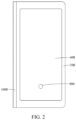
- the included angle between the first housing 100 and the second housing 200 is 180°, as shown in FIG. 1 ; or when the electronic device is in the folded state, the included angle between the first housing 100 and the second housing 200 is 0°, as shown in FIG. 2 .
- the first display 300 may include a first sub-screen 310 and a second sub-screen 320, the first sub-screen 310 is correspondingly connected to the first housing 100, and the second sub-screen 320 is correspondingly connected to the second housing 200.
- the first housing 100 is a carrier of the first sub-screen 310
- the second housing 200 is a carrier of the second sub-screen 320.
- the first display 300 may further include a third sub-screen, and the first sub-screen 310 is connected to the second sub-screen 320 through the third sub-screen, so that the first sub-screen 310, the second sub-screen 320, and the third sub-screen jointly form the complete display area of the first display 300.
- the third sub-screen corresponds to an area between the first housing 100 and the second housing 200, and specifically may correspond to the rotating hinge 1000, so that the third sub-screen is deformed in a process of folding the electronic device.
- the third sub-screen may be independently displayed.
- both the first display 300 and the second display 400 are provided with light-transmitting areas; the fingerprint module 500 is disposed in the first housing 100; and the dimming module 600 is disposed in the second housing 200 and is located between the light-transmitting area of the first display 300 and the light-transmitting area of the second display 400, where when the electronic device is in the unfolded state, the dimming module 600 is in a light blocking state, and the fingerprint module 500 performs fingerprint identification through the light-transmitting area of the first display 300; or when the electronic device is in the folded state, the dimming module 600 is in a light-through state, and the fingerprint module 500 performs fingerprint identification through the light-transmitting areas of the first display 300 and the second display 400.
- the electronic device uses an optical fingerprint identification technology.
- the optical fingerprint identification technology means that when a finger presses a fingerprint identification area of the display, a built-in module of the display emits light to illuminate the fingerprint identification area, the light illuminating a fingerprint is reflected and passes through the display, and is projected to a fingerprint sensor inside the electronic device, and the fingerprint sensor compares the reflected light with pre-entered fingerprint image information, to perform identification determining.
- the dimming module 600 is configured to adjust a light-through amount, and may be connected to a circuit board 800 of the electronic device.
- the light-transmitting areas of the first display 300 and the second display 400 are used to transmit light, so that the light illuminating the fingerprint can be smoothly transmitted to the corresponding display after being reflected, to be projected to the fingerprint module 500 (namely, the fingerprint sensor) inside the electronic device.
- Both the first sub-screen 310 and the second sub-screen 320 of the first display 300 have light-transmitting areas, so that the dimming module 600 is located between the light-transmitting area of the second sub-screen 320 of the first display 300 and the light-transmitting area of the second display 400.
- the second housing 200 may be provided with a first light-through hole 210 corresponding to the light-transmitting area and the dimming module 600.
- the user uses the first display 300, and the user may press the fingerprint identification area 900 of the first display 300.
- the area corresponds to the fingerprint module 500, and the light illuminating may pass through the light-transmitting area of the first display 300 and is smoothly reflected to the fingerprint module 500 in the first housing 100, to implement fingerprint identification.
- the light blocking state of the dimming module 600 is a state in which light transmission is prevented, and the dimming module 600 is located between the light-transmitting area of the first display 300 and the light-transmitting area of the second display 400.
- an area that is of the first display 300 and that corresponds to the dimming module 600 is a non-light-transmitting area, so that a light-transmitting difference occurred between the area and another area of the first display 300 can be avoided, that is, a "perspectivity" problem is avoided, to ensure that an overall screen of the first display 300 is consistent in color, and optimal display effect is achieved.
- the first display 300 is folded inside the electronic device, and the second display 400 is located outside the electronic device, so that the user can use the second display 400, and the user can press the second display 400 in the fingerprint identification area 900 preset on the second display 400.
- the light-transmitting area of the second display 400 is correspondingly disposed with two light-transmitting areas (the light-transmitting areas of the first sub-screen 310 and the second sub-screen 320) of the first display 300, and the dimming module 600 is in the light-through state, that is, the dimming module 600 allows the fingerprint light to pass through, so that the light illuminating the fingerprint can sequentially pass through the light-transmitting areas of the second display 400, the second sub-screen 320, and the first sub-screen 310 and is smoothly reflected to the fingerprint module 500 in the first housing 100, to implement fingerprint identification.
- the electronic device in embodiments of this application can implement a dual-screen fingerprint identification function of the foldable electronic device by setting only one fingerprint module 500, thereby effectively simplifying a structure of the electronic device undoubtedly.
- the electronic device in embodiments of this application can reduce a quantity of fingerprint modules 500, so that stacking space inside the electronic device can be saved, a circuit layout can be reduced, and costs can be further reduced, thereby implementing a light and thin design of the electronic device.
- the dimming module 600 is an electro-deformation assembly.
- the electro-deformation assembly When the electronic device is in the unfolded state, the electro-deformation assembly is in a colored state, thereby implementing light blocking; or when the electronic device is in the folded state, the electro-deformation assembly is in a transparent state, thereby implementing light-through.
- the dimming module 600 may include a first driving assembly 620 and a plurality of blades 630, the plurality of blades 630 are arranged along a circumferential direction of an optical path of fingerprint light and are all movably disposed in the second housing 200 between a first position and a second position, and when the plurality of blades 630 are in the first position, the plurality of blades 630 are spliced with each other to block the optical path; or when the plurality of blades 630 are in the second position, the plurality of blades 630 give way to the optical path; and the first driving assembly 620 is connected to the plurality of blades 630 and is configured to drive the plurality of blades 630 to move.
- the first driving assembly 620 is configured to drive the blade 630, to enable the blade 630 to move between the first position and the second position.
- the plurality of blades 630 block the optical path, that is, light is prevented from being propagated, so that the dimming module 600 is in the light blocking state; or when the plurality of blades 630 are in the second position, the plurality of blades 630 all give way to the optical path, so that light can be smoothly propagated, and the dimming module 600 is in the light-through state.
- an area surrounded by the plurality of blades 630 may form an avoidance hole through which the fingerprint light can pass, and the avoidance hole may change a size by switching the blades 630 between the first position and the second position, thereby changing a light-through amount of the fingerprint light. Because in the solution that the plurality of blades 630 are spliced, it is determined that the blades 630 all approximately move along a radial direction, the avoidance hole is always on the optical path of the fingerprint light.
- the light-through amount of the fingerprint light may be adjusted by adjusting the size of the avoidance hole, and propagation of the fingerprint light on the optical path of the fingerprint light can be ensured. Finally, sensitivity of the fingerprint identification function of the electronic device is adjusted, to meet requirements of different users.
- the plurality of blades 630 in embodiments of this application are arranged along the circumferential direction of the optical path of the fingerprint light, so that an excessively large size of the electronic device in a single direction can be avoided, thereby optimizing an internal structure layout of the device.
- the dimming module 600 may further include a substrate 610, a second light-through hole 611 is provided on the substrate 610, the second light-through hole 611 is correspondingly provided with the optical path, and the blade 630 is movably disposed on the substrate 610; and one of the blade 630 and the substrate 610 is provided with a guide groove 612, and the other is provided with a fitting portion 632, and the fitting portion 632 is movably disposed in the guide groove 612.
- the second light-through hole 611 may be used for light to pass through, so that it can be ensured that the optical path can be smoothly formed inside the dimming module 600 when the dimming module 600 is in the light-through state.
- the substrate 610 is a carrier, of the blade 630, that is movably disposed, and the substrate 610 is used as an independent structure, so that it is more convenient to process a fitting structure with the blade 630.
- the fitting portion 632 is disposed on the blade 630, and the guide groove 612 is provided on the substrate 610.
- the fitting portion 632 may be provided on the substrate 610, and the guide groove 612 is provided on the blade 630.
- Specific setting positions of the fitting portion 632 and the guide groove 612 are not limited in embodiments of this application.
- the fitting portion 632 is generally a protruding structure.
- a fitting relationship between the fitting portion 632 and the guide groove 612 not only implements a movable setting of the blade 630 on the substrate 610, but also implements a guide function of the guide groove 612 for a movement action of the blade 630 through the fitting portion 632, to ensure that the blade 630 can accurately move between the first position and the second position, thereby improving accuracy of a moving path of the blade 630 and stability of accurate switching of the dimming module 600 between the light blocking state and the light-through state.
- the blade 630 in embodiments of this application may directly fit with the second housing 200 through guided movement, and the substrate 610 does not need to be disposed on the electronic device.
- the blade 630 has a splicing corner 631
- the blade 630 includes a first side wall and a second side wall located on both sides of the splicing corner 631, the blade 630 abuts against splicing corners 631 of two adjacent blades 630 through the first side wall and the second side wall respectively, and the first driving assembly 620 is connected to one of the blades 630; and when the first driving assembly 620 drives the blade 630 to move toward the first position, the blade 630 pushes the blade 630 that abuts against the first side wall of the blade 630 to block the optical path; or when the first driving assembly 620 drives the blade 630 to move toward the second position, the blade 630 pushes the blade 630 that abuts against the second side wall of the blade 630 to give way to the optical path.
- the blades 630 may be spliced at a vertex of the splicing corner 631, so that the blades 630 are completely spliced around by one circle, thereby ensuring that the optical path of the light is completely blocked.
- each of the blades 630 may abut against splicing corners 631 of two adjacent blades 630 through the first side wall and the second side wall, to be specific, along the circumferential direction of the optical path of the fingerprint light, the plurality of blades 630 are sequentially arranged, and each of the blades 630 abuts against the adjacent blades 630 through the first side wall and the second side wall respectively.
- the blade 630 pushes the adjacent blade 630 to move through the first side wall, so that all the blades 630 along the circumferential direction of the optical path of the fingerprint light move toward the first position, thereby implementing switching of the dimming module 600 from the light-through state to the light blocking state.
- the blade 630 pushes the adjacent blade 630 to move through the second side wall, so that all the blades 630 along the circumferential direction of the optical path of the fingerprint light move toward the second position, thereby implementing switching of the dimming module 600 from the light blocking state to the light-through state.
- the first driving assembly 620 in embodiments of this application drives one blade 630, and then the blade 630 can drive all blades 630 to move.
- each blade 630 is configured with one driving apparatus, costs and stacking space inside the electronic device are effectively saved.
- a quantity of blades 630 is not limited. As shown in FIG. 6 and FIG. 8 , there may be six blades 630, or there may be another quantity of blades 630 such as four or five.
- the first driving assembly 620 is an electro-deformation assembly, and the electro-deformation assembly drives the blade 630 to move through telescopic deformation.
- the electro-deformation assembly may conveniently implement a driving function for the blade 630 by powering on or off, thereby facilitating switching of the dimming module 600 between the light blocking state and the light-through state.
- a structure of the electro-deformation assembly is simple, and the internal structure layout of the electronic device can be simplified.
- the first driving assembly 620 may be a linear motor 653, a hydraulic telescopic part, or the like.
- the electro-deformation assembly may include an electrical heating component 621 and a shape memory alloy part 622, the electrical heating component 621 is configured to heat the shape memory alloy part 622, and the shape memory alloy part 622 is connected to the blade 630.
- the electrical heating component 621 is an excitation component of the shape memory alloy part 622, and an excitation signal is sent to the electrical heating component 621, so that the electrical heating component 621 can transmit energy to the shape memory alloy part 622, and the shape memory alloy part 622 implements a telescopic action, to drive the blade 630 to move.
- the shape memory alloy part 622 may be a shape memory alloy wire.
- the electro-deformation assembly may further be made of an electroactive polymer (Electroactive Polymer, EAP), a piezoelectric material, or the like.
- EAP Electroactive Polymer
- the dimming module 600 may include a baffle 640 and a second driving assembly 650, the baffle 640 is movably disposed in the second housing 200 between a third position and a fourth position, and when the baffle 640 is in the third position, the baffle 640 blocks the optical path of the fingerprint light; or when the baffle 640 is in the fourth position, the baffle 640 gives way to the optical path; and the second driving assembly 650 is connected to the baffle 640 and is configured to drive the baffle 640 to move.
- the second driving assembly 650 is a driving apparatus corresponding to the baffle 640.
- the baffle 640 In a process in which the baffle 640 is driven to move from the fourth position to the third position, the baffle 640 gradually blocks the optical path of the fingerprint light, thereby implementing switching of the dimming module 600 from the light-through state to the light blocking state.
- the baffle 640 In a process in which the baffle 640 is driven to move from the third position to the fourth position, the baffle 640 gradually gives way to the optical path of the fingerprint light, thereby implementing switching of the dimming module 600 from the light blocking state to the light-through state. In this way, a structure of the driving solution through the driving baffle 640 is simple, and the internal structure layout of the electronic device can be simplified.
- the second driving assembly 650 may include an electromagnet apparatus 651 and an elastic member 652, the baffle 640 is a magnetic mechanical part, and the electromagnet apparatus 651 and the elastic member 652 are respectively disposed on two opposite sides of the baffle 640; and one of the electromagnet apparatus 651 and the elastic member 652 is configured to drive the baffle 640 to move to the third position, and the other is configured to drive the baffle 640 to move to the fourth position.
- the baffle 640 is a magnetic mechanical part
- the electromagnet apparatus 651 implements a driving function for the baffle 640 by using a magnetic field force.
- the elastic member 652 may store energy when being compressed. In this case, a resilient force may be applied to the baffle 640.
- the elastic member 652 may store energy when being stretched. In this case, a pulling force may be applied to the baffle 640. In both the two states, a driving function may be applied to the baffle 640.
- the electromagnet apparatus 651 can change a size of the driving function through powering-on strength. Therefore, it is more convenient to control adjustment accuracy, and a structure of the electromagnetic driving solution is simple.
- a specific driving relationship between each of the electromagnet apparatus 651 and the elastic member 652 and the baffle 640 is not limited.
- the elastic member 652 may be selected as a spring, or the elastic member 652 may be foam, rubber, an elastic polymer material, or the like.
- the electromagnet apparatus 651 when the electromagnet apparatus 651 is powered on, the electromagnet apparatus 651 applies an attraction force to the baffle 640 to drive the baffle 640 to move to the third position, and the elastic member 652 is in a stretched state and stores energy; or when the electromagnet apparatus 651 is powered off, the elastic member 652 retracts and releases energy to apply a pulling force to the baffle 640 to drive the baffle 640 to move to the fourth position.
- the electromagnet apparatus 651 when the electromagnet apparatus 651 is powered on, the electromagnet apparatus 651 may apply a repulsion force to the baffle 640 to drive the baffle 640 to move to the fourth position, and the elastic member 652 is in a compressed state and stores energy; or when the electromagnet apparatus is powered off, the elastic member 652 rebounds to extend and releases energy to apply a thrust force to the baffle 640 to drive the baffle 640 to move to the third position.
- the second driving assembly 650 may include a motor 653 and a transmission gear 654, the baffle 640 includes a rack portion 641 at one end, close to the motor 653, of the baffle 640, the transmission gear 654 is disposed at an output end of the motor 653, and the transmission gear 654 meshes with the rack portion 641.
- the transmission gear 654 may rotate with the output end of the motor 653, and the rack portion 641 may move with the transmission gear 654, to drive the baffle 640 to move.
- the baffle 640 may move between the third position and the fourth position by adjusting and controlling an output rotation direction of the motor 653 to be different.
- the rack portion 641 moves in a straight line, so that relative rotation does not occur, thereby reducing a probability of interference with another component in a transmission process, and facilitating arrangement of another component in an internal environment of the device.
- the electronic device may further include a light-transmitting support plate 700, the light-transmitting support plate 700 is disposed in the second housing 200 and is located between the dimming module 600 and the first display 300, and the first display 300 is attached to the light-transmitting support plate 700.
- the light-transmitting support plate 700 may transmit the fingerprint light, so that it can be ensured that the fingerprint identification function can be smoothly implemented.
- An area in which the dimming module 600 is located belongs to an area with relative weak strength inside the second housing 200. In this case, the light-transmitting support plate 700 may improve the strength of the area, to optimize structure stability of the electronic device.
- the dimming module 600 is an implementation solution such as splicing the blades 630 or moving the baffle 640
- a support function of the blade 630 or the baffle 640 is weakened, and the light-transmitting support plate 700 may always implement a good support function for the first display 300. Even if the first display 300 is a flexible foldable screen, better structure stability can be ensured.
- the electronic device disclosed in embodiments of this application may be a smartphone, a tablet computer, an e-book reader, a wearable device (for example, a smart watch), a video game console, or the like.
- a type of the electronic device is not specifically limited in embodiments of this application.
Landscapes
- Engineering & Computer Science (AREA)
- Theoretical Computer Science (AREA)
- Physics & Mathematics (AREA)
- Human Computer Interaction (AREA)
- General Physics & Mathematics (AREA)
- Computer Hardware Design (AREA)
- General Engineering & Computer Science (AREA)
- Multimedia (AREA)
- Mathematical Physics (AREA)
- Devices For Indicating Variable Information By Combining Individual Elements (AREA)
- Image Input (AREA)
Abstract
Description
- This application claims priority to
Chinese Patent Application No. 202210945780.1, filed with the China National Intellectual Property Administration on August 8, 2022 - This application pertains to the field of communication device technologies, and specifically relates to an electronic device.
- With continuous development of technologies, to improve use experience when a user watches videos and plays games, a screen size of an electronic device is designed to be increasingly large. However, an increase in the screen size also means an increase in a size of the whole device, which results in poor portability of the electronic device. In this regard, the industry considers requirements of the foregoing two aspects by using a foldable screen technology.
- In a related technology, an electronic device has a foldable screen and a cover display. In an unfolded state, the foldable screen of the electronic device can be used, and in a folded state, the cover display of the electronic device can be used. In the electronic device that uses an under-display fingerprint unlocking solution, under-display fingerprint modules need to be disposed on lower sides of both the foldable screen and the cover display. Consequently, this structure layout apparently complicates a structure of the electronic device.
- An objective of embodiments of this application is to provide an electronic device, so that a structure of the electronic device can be simplified.
- To resolve the foregoing technical problem, this application is implemented as follows:
Embodiments of this application provide an electronic device. The device includes: a first housing; a second housing, rotatably connected to the first housing, to enable the electronic device to switch between a folded state and an unfolded state; a first display, where two ends of the first display are respectively connected to the first housing and the second housing, and can be folded or unfolded with relative rotation of the first housing and the second housing; a second display, disposed on a side, opposite to the first display, of the second housing, where both the first display and the second display are provided with light-transmitting areas; a fingerprint module, disposed in the first housing; and a dimming module, disposed in the second housing and located between the light-transmitting area of the first display and the light-transmitting area of the second display, where when the electronic device is in the unfolded state, the dimming module is in a light blocking state, and the fingerprint module performs fingerprint identification through the light-transmitting area of the first display; or when the electronic device is in the folded state, the dimming module is in a light-through state, and the fingerprint module performs fingerprint identification through the light-transmitting areas of the first display and the second display. - In the electronic device disclosed in embodiments of this application, the dimming module configured to adjust a light-through amount is disposed in the first housing. When the electronic device is in the unfolded state, a user may perform fingerprint identification through the first display, and the dimming module can prevent light from passing through, so that areas corresponding to the dimming module on the first display and the second display are non-light-transmitting areas, thereby optimizing display effect of the first display; or when the electronic device is in the folded state, a user may perform fingerprint identification through the second display, the dimming module can allow fingerprint light passing through the second display to pass through, and the fingerprint light passes through the light-transmitting area of the first display and is projected to the fingerprint module, to implement fingerprint identification.
- In comparison with a related technology, the electronic device in embodiments of this application can implement a dual-screen fingerprint identification function of the foldable electronic device by setting only one fingerprint module, thereby effectively simplifying a structure of the electronic device.
-
-
FIG. 1 andFIG. 2 are respectively schematic diagrams of structures of an electronic device in an unfolded state and a folded state according to an embodiment of this application; -
FIG. 3 is a first schematic diagram of an exploded structure of an electronic device according to an embodiment of this application; -
FIG. 4 is a first sectional view of an electronic device according to an embodiment of this application; -
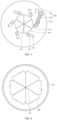
FIG. 5 and FIG. 6 are respectively a first top view and a first bottom view of blocking an optical path by a dimming module according to an embodiment of this application; -
FIG. 7 and FIG. 8 are respectively a first top view and a first bottom view of giving way to an optical path by a dimming module according to an embodiment of this application; -
FIG. 9 is a second schematic diagram of an exploded structure of an electronic device according to an embodiment of this application; -
FIG. 10 is a second sectional view of an electronic device according to an embodiment of this application; -
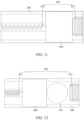
FIG. 11 is a second top view of blocking an optical path by a dimming module according to an embodiment of this application; -
FIG. 12 is a second top view of giving way to an optical path by a dimming module according to an embodiment of this application; -
FIG. 13 is a third schematic diagram of an exploded structure of an electronic device according to an embodiment of this application; -
FIG. 14 is a third sectional view of an electronic device according to an embodiment of this application; -
FIG. 15 is a third top view of blocking an optical path by a dimming module according to an embodiment of this application; and -
FIG. 16 is a third top view of giving way to an optical path by a dimming module according to an embodiment of this application. -
- 100: first housing; 200: second housing; 210: first light-through hole;
- 300: first display; 310: first sub-screen; 320: second sub-screen;
- 400: second display; 500: fingerprint module;
- 600: dimming module; 610: substrate; 611: second light-through hole; 612: guide groove; 620: first driving assembly; 621: electrical heating component; 622: shape memory alloy part; 630: blade; 631: splicing corner; 632: fitting portion; 640: baffle; 641: rack portion; 650: second driving assembly; 651: electromagnet apparatus; 652: elastic member; 653: motor; 654: transmission gear;
- 700: light-transmitting support plate; 800: circuit board; 900: fingerprint identification area; 1000: rotating hinge.
- The following clearly describes technical solutions in embodiments of this application with reference to accompanying drawings in embodiments of this application. Apparently, the described embodiments are some but not all of embodiments of this application. All other embodiments obtained by a person of ordinary skill based on embodiments of this application shall fall within the protection scope of this application.
- The terms "first", "second", and the like in this specification and the claims of this application are used to distinguish between similar objects instead of describing a specific order or sequence. It should be understood that the terms used in such a way are interchangeable in proper circumstances, so that embodiments of this application can be implemented in an order other than the order illustrated or described herein. Objects classified by "first", "second", and the like are usually of a same type, and a quantity of objects is not limited. For example, there may be one or more first objects. In addition, in this specification and the claims, "and/or" indicates at least one of connected objects, and a character "/" generally indicates an "or" relationship between associated objects.
- The technical solutions disclosed in embodiments of this application are described in detail below with reference to the accompanying drawings.
- To resolve a technical problem in the related technology that under-display fingerprint modules need to be disposed on lower sides of both a foldable screen and a cover display of an electronic device, and consequently a structure is excessively complex, embodiments of this application provide an electronic device.
- Refer to
FIG. 1 to FIG. 16 . The electronic device disclosed in embodiments of this application includes afirst housing 100, asecond housing 200, afirst display 300, asecond display 400, afingerprint module 500, and adimming module 600. - The
first housing 100 and thesecond housing 200 are basic components of the electronic device, and can provide a mounting basis for components such as thefirst display 300, thesecond display 400, thefingerprint module 500, and thedimming module 600 in the electronic device. - The
second housing 200 is rotatably connected to thefirst housing 100, that is, relative rotation can be generated between thefirst housing 100 and thesecond housing 200, so that the electronic device can switch between a folded state and an unfolded state. The electronic device may include arotating hinge 1000, and thefirst housing 100 and thesecond housing 200 implement rotation fit through therotating hinge 1000. - Two ends of the
first display 300 are respectively connected to thefirst housing 100 and thesecond housing 200, and can be folded or unfolded with relative rotation of thefirst housing 100 and thesecond housing 200. Thesecond display 400 is disposed on a side, opposite to thefirst display 300, of thesecond housing 200. - Specifically, the
first display 300 is a flexible foldable screen of the electronic device, and relative to thefirst display 300, thesecond display 400 is a cover display of the electronic device. When the electronic device is in the unfolded state, a display area of thefirst display 300 is large, so that a requirement of a user for a large display is met; or when the electronic device is in the folded state, an overall size of the electronic device is small, so that a user can implement a display function of the electronic device through thesecond display 400, and it is convenient for the user to carry and hold the electronic device. - In embodiments of this application, a specific included angle between the
first housing 100 and thesecond housing 200 when the electronic device is in the unfolded state or the folded state is not limited. Optionally, when the electronic device is in the unfolded state, the included angle between thefirst housing 100 and thesecond housing 200 is 180°, as shown inFIG. 1 ; or when the electronic device is in the folded state, the included angle between thefirst housing 100 and thesecond housing 200 is 0°, as shown inFIG. 2 . - The
first display 300 may include afirst sub-screen 310 and asecond sub-screen 320, thefirst sub-screen 310 is correspondingly connected to thefirst housing 100, and thesecond sub-screen 320 is correspondingly connected to thesecond housing 200. In this layout, thefirst housing 100 is a carrier of thefirst sub-screen 310, and thesecond housing 200 is a carrier of thesecond sub-screen 320. When thefirst housing 100 and thesecond housing 200 are unfolded or folded, thefirst sub-screen 310 and thesecond sub-screen 320 may be driven to be unfolded or folded. Thefirst sub-screen 310 and the second sub-screen 320 may be independently displayed. - The
first display 300 may further include a third sub-screen, and thefirst sub-screen 310 is connected to the second sub-screen 320 through the third sub-screen, so that the first sub-screen 310, thesecond sub-screen 320, and the third sub-screen jointly form the complete display area of thefirst display 300. The third sub-screen corresponds to an area between thefirst housing 100 and thesecond housing 200, and specifically may correspond to therotating hinge 1000, so that the third sub-screen is deformed in a process of folding the electronic device. The third sub-screen may be independently displayed. - In addition, both the
first display 300 and thesecond display 400 are provided with light-transmitting areas; thefingerprint module 500 is disposed in thefirst housing 100; and thedimming module 600 is disposed in thesecond housing 200 and is located between the light-transmitting area of thefirst display 300 and the light-transmitting area of thesecond display 400, where when the electronic device is in the unfolded state, the dimmingmodule 600 is in a light blocking state, and thefingerprint module 500 performs fingerprint identification through the light-transmitting area of thefirst display 300; or when the electronic device is in the folded state, the dimmingmodule 600 is in a light-through state, and thefingerprint module 500 performs fingerprint identification through the light-transmitting areas of thefirst display 300 and thesecond display 400. - Specifically, in embodiments of this application, the electronic device uses an optical fingerprint identification technology. The optical fingerprint identification technology means that when a finger presses a fingerprint identification area of the display, a built-in module of the display emits light to illuminate the fingerprint identification area, the light illuminating a fingerprint is reflected and passes through the display, and is projected to a fingerprint sensor inside the electronic device, and the fingerprint sensor compares the reflected light with pre-entered fingerprint image information, to perform identification determining.
- The dimming
module 600 is configured to adjust a light-through amount, and may be connected to acircuit board 800 of the electronic device. The light-transmitting areas of thefirst display 300 and thesecond display 400 are used to transmit light, so that the light illuminating the fingerprint can be smoothly transmitted to the corresponding display after being reflected, to be projected to the fingerprint module 500 (namely, the fingerprint sensor) inside the electronic device. Both thefirst sub-screen 310 and thesecond sub-screen 320 of thefirst display 300 have light-transmitting areas, so that thedimming module 600 is located between the light-transmitting area of thesecond sub-screen 320 of thefirst display 300 and the light-transmitting area of thesecond display 400. To ensure that fingerprint light can be smoothly propagated, thesecond housing 200 may be provided with a first light-throughhole 210 corresponding to the light-transmitting area and thedimming module 600. - As shown in
FIG. 1 , when the electronic device is in the unfolded state, the user uses thefirst display 300, and the user may press thefingerprint identification area 900 of thefirst display 300. The area corresponds to thefingerprint module 500, and the light illuminating may pass through the light-transmitting area of thefirst display 300 and is smoothly reflected to thefingerprint module 500 in thefirst housing 100, to implement fingerprint identification. It should be noted that the light blocking state of thedimming module 600 is a state in which light transmission is prevented, and thedimming module 600 is located between the light-transmitting area of thefirst display 300 and the light-transmitting area of thesecond display 400. When the electronic device is in the unfolded state, an area that is of thefirst display 300 and that corresponds to thedimming module 600 is a non-light-transmitting area, so that a light-transmitting difference occurred between the area and another area of thefirst display 300 can be avoided, that is, a "perspectivity" problem is avoided, to ensure that an overall screen of thefirst display 300 is consistent in color, and optimal display effect is achieved. - As shown in
FIG. 2 , when the electronic device is in the folded state, thefirst display 300 is folded inside the electronic device, and thesecond display 400 is located outside the electronic device, so that the user can use thesecond display 400, and the user can press thesecond display 400 in thefingerprint identification area 900 preset on thesecond display 400. In addition, when the electronic device is in the folded state, the light-transmitting area of thesecond display 400 is correspondingly disposed with two light-transmitting areas (the light-transmitting areas of thefirst sub-screen 310 and the second sub-screen 320) of thefirst display 300, and thedimming module 600 is in the light-through state, that is, the dimmingmodule 600 allows the fingerprint light to pass through, so that the light illuminating the fingerprint can sequentially pass through the light-transmitting areas of thesecond display 400, thesecond sub-screen 320, and thefirst sub-screen 310 and is smoothly reflected to thefingerprint module 500 in thefirst housing 100, to implement fingerprint identification. - In comparison with a related technology, the electronic device in embodiments of this application can implement a dual-screen fingerprint identification function of the foldable electronic device by setting only one
fingerprint module 500, thereby effectively simplifying a structure of the electronic device undoubtedly. Specifically, the electronic device in embodiments of this application can reduce a quantity offingerprint modules 500, so that stacking space inside the electronic device can be saved, a circuit layout can be reduced, and costs can be further reduced, thereby implementing a light and thin design of the electronic device. - In embodiments of this application, there are a plurality of types of dimming
modules 600. For example, the dimmingmodule 600 is an electro-deformation assembly. When the electronic device is in the unfolded state, the electro-deformation assembly is in a colored state, thereby implementing light blocking; or when the electronic device is in the folded state, the electro-deformation assembly is in a transparent state, thereby implementing light-through. - In another implementation solution of the
dimming module 600, as shown inFIG. 3 to FIG. 8 , the dimmingmodule 600 may include a first driving assembly 620 and a plurality ofblades 630, the plurality ofblades 630 are arranged along a circumferential direction of an optical path of fingerprint light and are all movably disposed in thesecond housing 200 between a first position and a second position, and when the plurality ofblades 630 are in the first position, the plurality ofblades 630 are spliced with each other to block the optical path; or when the plurality ofblades 630 are in the second position, the plurality ofblades 630 give way to the optical path; and the first driving assembly 620 is connected to the plurality ofblades 630 and is configured to drive the plurality ofblades 630 to move. - In this structure layout, the first driving assembly 620 is configured to drive the
blade 630, to enable theblade 630 to move between the first position and the second position. When the plurality ofblades 630 are in the first position, the plurality ofblades 630 block the optical path, that is, light is prevented from being propagated, so that thedimming module 600 is in the light blocking state; or when the plurality ofblades 630 are in the second position, the plurality ofblades 630 all give way to the optical path, so that light can be smoothly propagated, and thedimming module 600 is in the light-through state. - In such a solution that the plurality of
blades 630 are spliced, an area surrounded by the plurality ofblades 630 may form an avoidance hole through which the fingerprint light can pass, and the avoidance hole may change a size by switching theblades 630 between the first position and the second position, thereby changing a light-through amount of the fingerprint light. Because in the solution that the plurality ofblades 630 are spliced, it is determined that theblades 630 all approximately move along a radial direction, the avoidance hole is always on the optical path of the fingerprint light. In this way, even if the avoidance hole is small by driving theblades 630 to be spliced, it can still be ensured that the fingerprint light passes through the avoidance hole, thereby ensuring that the fingerprint identification function can be smoothly implemented. Certainly, when less fingerprint light passes through, sensitivity of the fingerprint identification function decreases. - It can be learned that, in the solution that the plurality of
blades 630 are spliced in embodiments of this application, the light-through amount of the fingerprint light may be adjusted by adjusting the size of the avoidance hole, and propagation of the fingerprint light on the optical path of the fingerprint light can be ensured. Finally, sensitivity of the fingerprint identification function of the electronic device is adjusted, to meet requirements of different users. - In addition, the plurality of
blades 630 in embodiments of this application are arranged along the circumferential direction of the optical path of the fingerprint light, so that an excessively large size of the electronic device in a single direction can be avoided, thereby optimizing an internal structure layout of the device. - Further, as shown in
FIG. 4 to FIG. 8 , the dimmingmodule 600 may further include asubstrate 610, a second light-throughhole 611 is provided on thesubstrate 610, the second light-throughhole 611 is correspondingly provided with the optical path, and theblade 630 is movably disposed on thesubstrate 610; and one of theblade 630 and thesubstrate 610 is provided with aguide groove 612, and the other is provided with afitting portion 632, and thefitting portion 632 is movably disposed in theguide groove 612. - In this setting, the second light-through
hole 611 may be used for light to pass through, so that it can be ensured that the optical path can be smoothly formed inside the dimmingmodule 600 when thedimming module 600 is in the light-through state. Thesubstrate 610 is a carrier, of theblade 630, that is movably disposed, and thesubstrate 610 is used as an independent structure, so that it is more convenient to process a fitting structure with theblade 630. - As shown in
FIG. 5 andFIG. 7 , thefitting portion 632 is disposed on theblade 630, and theguide groove 612 is provided on thesubstrate 610. Certainly, thefitting portion 632 may be provided on thesubstrate 610, and theguide groove 612 is provided on theblade 630. Specific setting positions of thefitting portion 632 and theguide groove 612 are not limited in embodiments of this application. Thefitting portion 632 is generally a protruding structure. It should be understood that a fitting relationship between thefitting portion 632 and theguide groove 612 not only implements a movable setting of theblade 630 on thesubstrate 610, but also implements a guide function of theguide groove 612 for a movement action of theblade 630 through thefitting portion 632, to ensure that theblade 630 can accurately move between the first position and the second position, thereby improving accuracy of a moving path of theblade 630 and stability of accurate switching of thedimming module 600 between the light blocking state and the light-through state. - In another implementation solution, the
blade 630 in embodiments of this application may directly fit with thesecond housing 200 through guided movement, and thesubstrate 610 does not need to be disposed on the electronic device. - Further, as shown in
FIG. 5 to FIG. 8 , theblade 630 has asplicing corner 631, theblade 630 includes a first side wall and a second side wall located on both sides of thesplicing corner 631, theblade 630 abuts againstsplicing corners 631 of twoadjacent blades 630 through the first side wall and the second side wall respectively, and the first driving assembly 620 is connected to one of theblades 630; and when the first driving assembly 620 drives theblade 630 to move toward the first position, theblade 630 pushes theblade 630 that abuts against the first side wall of theblade 630 to block the optical path; or when the first driving assembly 620 drives theblade 630 to move toward the second position, theblade 630 pushes theblade 630 that abuts against the second side wall of theblade 630 to give way to the optical path. - It should be understood that the
blades 630 may be spliced at a vertex of thesplicing corner 631, so that theblades 630 are completely spliced around by one circle, thereby ensuring that the optical path of the light is completely blocked. Specifically, each of theblades 630 may abut againstsplicing corners 631 of twoadjacent blades 630 through the first side wall and the second side wall, to be specific, along the circumferential direction of the optical path of the fingerprint light, the plurality ofblades 630 are sequentially arranged, and each of theblades 630 abuts against theadjacent blades 630 through the first side wall and the second side wall respectively. - In a process in which the
blade 630 is driven to move from the second position to the first position, theblade 630 pushes theadjacent blade 630 to move through the first side wall, so that all theblades 630 along the circumferential direction of the optical path of the fingerprint light move toward the first position, thereby implementing switching of thedimming module 600 from the light-through state to the light blocking state. In a process in which theblade 630 is driven to move from the first position to the second position, theblade 630 pushes theadjacent blade 630 to move through the second side wall, so that all theblades 630 along the circumferential direction of the optical path of the fingerprint light move toward the second position, thereby implementing switching of thedimming module 600 from the light blocking state to the light-through state. - Apparently, the first driving assembly 620 in embodiments of this application drives one
blade 630, and then theblade 630 can drive allblades 630 to move. In comparison with those in a solution that eachblade 630 is configured with one driving apparatus, costs and stacking space inside the electronic device are effectively saved. - In embodiments of this application, a quantity of
blades 630 is not limited. As shown inFIG. 6 andFIG. 8 , there may be sixblades 630, or there may be another quantity ofblades 630 such as four or five. - Further, as shown in
FIG. 4 ,FIG. 5 , andFIG. 7 , the first driving assembly 620 is an electro-deformation assembly, and the electro-deformation assembly drives theblade 630 to move through telescopic deformation. It should be understood that, the electro-deformation assembly may conveniently implement a driving function for theblade 630 by powering on or off, thereby facilitating switching of thedimming module 600 between the light blocking state and the light-through state. A structure of the electro-deformation assembly is simple, and the internal structure layout of the electronic device can be simplified. - Certainly, a specific type of the first driving assembly 620 is not limited in embodiments of this application. For example, the first driving assembly 620 may be a
linear motor 653, a hydraulic telescopic part, or the like. - The electro-deformation assembly may include an
electrical heating component 621 and a shapememory alloy part 622, theelectrical heating component 621 is configured to heat the shapememory alloy part 622, and the shapememory alloy part 622 is connected to theblade 630. In this layout, theelectrical heating component 621 is an excitation component of the shapememory alloy part 622, and an excitation signal is sent to theelectrical heating component 621, so that theelectrical heating component 621 can transmit energy to the shapememory alloy part 622, and the shapememory alloy part 622 implements a telescopic action, to drive theblade 630 to move. The shapememory alloy part 622 may be a shape memory alloy wire. - In addition, the electro-deformation assembly may further be made of an electroactive polymer (Electroactive Polymer, EAP), a piezoelectric material, or the like.
- In another implementation solution of the
dimming module 600, as shown inFIG. 9 to FIG. 16 , the dimmingmodule 600 may include abaffle 640 and asecond driving assembly 650, thebaffle 640 is movably disposed in thesecond housing 200 between a third position and a fourth position, and when thebaffle 640 is in the third position, thebaffle 640 blocks the optical path of the fingerprint light; or when thebaffle 640 is in the fourth position, thebaffle 640 gives way to the optical path; and thesecond driving assembly 650 is connected to thebaffle 640 and is configured to drive thebaffle 640 to move. - In this implementation solution, the
second driving assembly 650 is a driving apparatus corresponding to thebaffle 640. In a process in which thebaffle 640 is driven to move from the fourth position to the third position, thebaffle 640 gradually blocks the optical path of the fingerprint light, thereby implementing switching of thedimming module 600 from the light-through state to the light blocking state. In a process in which thebaffle 640 is driven to move from the third position to the fourth position, thebaffle 640 gradually gives way to the optical path of the fingerprint light, thereby implementing switching of thedimming module 600 from the light blocking state to the light-through state. In this way, a structure of the driving solution through the drivingbaffle 640 is simple, and the internal structure layout of the electronic device can be simplified. - In a specific implementation solution of the
second driving assembly 650, as shown inFIG. 9 to FIG. 12 , thesecond driving assembly 650 may include anelectromagnet apparatus 651 and anelastic member 652, thebaffle 640 is a magnetic mechanical part, and theelectromagnet apparatus 651 and theelastic member 652 are respectively disposed on two opposite sides of thebaffle 640; and one of theelectromagnet apparatus 651 and theelastic member 652 is configured to drive thebaffle 640 to move to the third position, and the other is configured to drive thebaffle 640 to move to the fourth position. - It should be understood that, because the
baffle 640 is a magnetic mechanical part, when theelectromagnet apparatus 651 is powered on, theelectromagnet apparatus 651 implements a driving function for thebaffle 640 by using a magnetic field force. Theelastic member 652 may store energy when being compressed. In this case, a resilient force may be applied to thebaffle 640. Theelastic member 652 may store energy when being stretched. In this case, a pulling force may be applied to thebaffle 640. In both the two states, a driving function may be applied to thebaffle 640. - The
electromagnet apparatus 651 can change a size of the driving function through powering-on strength. Therefore, it is more convenient to control adjustment accuracy, and a structure of the electromagnetic driving solution is simple. - In embodiments of this application, a specific driving relationship between each of the
electromagnet apparatus 651 and theelastic member 652 and thebaffle 640 is not limited. As shown inFIG. 10 to FIG. 12 , theelastic member 652 may be selected as a spring, or theelastic member 652 may be foam, rubber, an elastic polymer material, or the like. - As shown in
FIG. 11 and FIG. 12 , when theelectromagnet apparatus 651 is powered on, theelectromagnet apparatus 651 applies an attraction force to thebaffle 640 to drive thebaffle 640 to move to the third position, and theelastic member 652 is in a stretched state and stores energy; or when theelectromagnet apparatus 651 is powered off, theelastic member 652 retracts and releases energy to apply a pulling force to thebaffle 640 to drive thebaffle 640 to move to the fourth position. - In another implementation solution, when the
electromagnet apparatus 651 is powered on, theelectromagnet apparatus 651 may apply a repulsion force to thebaffle 640 to drive thebaffle 640 to move to the fourth position, and theelastic member 652 is in a compressed state and stores energy; or when the electromagnet apparatus is powered off, theelastic member 652 rebounds to extend and releases energy to apply a thrust force to thebaffle 640 to drive thebaffle 640 to move to the third position. - In another specific implementation solution of the
second driving assembly 650, as shown inFIG. 13 to FIG. 16 , thesecond driving assembly 650 may include amotor 653 and atransmission gear 654, thebaffle 640 includes arack portion 641 at one end, close to themotor 653, of thebaffle 640, thetransmission gear 654 is disposed at an output end of themotor 653, and thetransmission gear 654 meshes with therack portion 641. - It should be understood that the
transmission gear 654 may rotate with the output end of themotor 653, and therack portion 641 may move with thetransmission gear 654, to drive thebaffle 640 to move. Specifically, thebaffle 640 may move between the third position and the fourth position by adjusting and controlling an output rotation direction of themotor 653 to be different. In the foregoing constructed gear-rack driving solution, therack portion 641 moves in a straight line, so that relative rotation does not occur, thereby reducing a probability of interference with another component in a transmission process, and facilitating arrangement of another component in an internal environment of the device. - In an optional solution, as shown in
FIG. 10 andFIG. 14 , the electronic device may further include a light-transmittingsupport plate 700, the light-transmittingsupport plate 700 is disposed in thesecond housing 200 and is located between the dimmingmodule 600 and thefirst display 300, and thefirst display 300 is attached to the light-transmittingsupport plate 700. - It should be understood that the light-transmitting
support plate 700 may transmit the fingerprint light, so that it can be ensured that the fingerprint identification function can be smoothly implemented. An area in which thedimming module 600 is located belongs to an area with relative weak strength inside thesecond housing 200. In this case, the light-transmittingsupport plate 700 may improve the strength of the area, to optimize structure stability of the electronic device. When thedimming module 600 is an implementation solution such as splicing theblades 630 or moving thebaffle 640, when thedimming module 600 is in the light-through state, a support function of theblade 630 or thebaffle 640 is weakened, and the light-transmittingsupport plate 700 may always implement a good support function for thefirst display 300. Even if thefirst display 300 is a flexible foldable screen, better structure stability can be ensured. - The electronic device disclosed in embodiments of this application may be a smartphone, a tablet computer, an e-book reader, a wearable device (for example, a smart watch), a video game console, or the like. A type of the electronic device is not specifically limited in embodiments of this application.
- Embodiments of this application are described above with reference to the accompanying drawings, but this application is not limited to the foregoing specific implementations, and the foregoing specific implementations are merely examples, but are not limitative. Under the enlightenment of this application, a person of ordinary skill in the art may further make many forms without departing from the purpose of this application and the protection scope of the claims, and all the forms fall within the protection of this application.
Claims (11)
- An electronic device, comprising:a first housing;a second housing, rotatably connected to the first housing, to enable the electronic device to switch between a folded state and an unfolded state;a first display, wherein two ends of the first display are respectively connected to the first housing and the second housing, and can be folded or unfolded with relative rotation of the first housing and the second housing;a second display, disposed on a side, opposite to the first display, of the second housing, wherein both the first display and the second display are provided with light-transmitting areas;a fingerprint module, disposed in the first housing; anda dimming module, disposed in the second housing and located between the light-transmitting area of the first display and the light-transmitting area of the second display, whereinwhen the electronic device is in the unfolded state, the dimming module is in a light blocking state, and the fingerprint module performs fingerprint identification through the light-transmitting area of the first display; when the electronic device is in the folded state, the dimming module is in a light-through state, and the fingerprint module performs fingerprint identification through the light-transmitting areas of the first display and the second display.
- The electronic device according to claim 1, wherein the dimming module comprises a first driving assembly and a plurality of blades, the plurality of blades are arranged along a circumferential direction of an optical path of fingerprint light and are all movably disposed in the second housing between a first position and a second position, and when the plurality of blades are in the first position, the plurality of blades are spliced with each other to block the optical path; when the plurality of blades are in the second position, the plurality of blades give way to the optical path; and the first driving assembly is connected to the plurality of blades and is configured to drive the plurality of blades to move.
- The electronic device according to claim 2, wherein the dimming module further comprises a substrate, a second light-through hole is provided on the substrate, the second light-through hole is correspondingly provided with the optical path, and the blade is movably disposed on the substrate; and
one of the blade and the substrate is provided with a guide groove, and the other is provided with a fitting portion, and the fitting portion is movably disposed in the guide groove. - The electronic device according to claim 2, wherein the blade has a splicing corner, the blade comprises a first side wall and a second side wall located on both sides of the splicing corner, the blade abuts against splicing corners of two adj acent blades through the first side wall and the second side wall respectively, and the first driving assembly is connected to one of the blades; and
when the first driving assembly drives the blade to move toward the first position, the blade pushes the blade that abuts against the first side wall of the blade to block the optical path; when the first driving assembly drives the blade to move toward the second position, the blade pushes the blade that abuts against the second side wall of the blade to give way to the optical path. - The electronic device according to claim 4, wherein the first driving assembly is an electro-deformation assembly, and the electro-deformation assembly drives the blade to move through telescopic deformation.
- The electronic device according to claim 5, wherein the electro-deformation assembly comprises an electrical heating component and a shape memory alloy part, the electrical heating component is configured to heat the shape memory alloy part, and the shape memory alloy part is connected to the blade.
- The electronic device according to claim 1, wherein the dimming module comprises a baffle and a second driving assembly, the baffle is movably disposed in the second housing between a third position and a fourth position, and when the baffle is in the third position, the baffle blocks an optical path of fingerprint light; or when the baffle is in the fourth position, the baffle gives way to the optical path; and the second driving assembly is connected to the baffle and is configured to drive the baffle to move.
- The electronic device according to claim 7, wherein the second driving assembly comprises an electromagnet apparatus and an elastic member, the baffle is a magnetic mechanical part, and the electromagnet apparatus and the elastic member are respectively disposed on two opposite sides of the baffle; and one of the electromagnet apparatus and the elastic member is configured to drive the baffle to move to the third position, and the other is configured to drive the baffle to move to the fourth position.
- The electronic device according to claim 8, wherein when the electromagnet apparatus is powered on, the electromagnet apparatus applies an attraction force to the baffle to drive the baffle to move to the third position; or when the electromagnet apparatus is powered off, the elastic member retracts to apply a pulling force to the baffle to drive the baffle to move to the fourth position.
- The electronic device according to claim 7, wherein the second driving assembly comprises a motor and a transmission gear, the baffle comprises a rack portion disposed at one end, close to the motor, of the baffle, the transmission gear is disposed at an output end of the motor, and the transmission gear meshes with the rack portion.
- The electronic device according to claim 1, wherein the electronic device further comprises a light-transmitting support plate, the light-transmitting support plate is disposed in the second housing and is located between the dimming module and the first display, and the first display is attached to the light-transmitting support plate.
Applications Claiming Priority (2)
| Application Number | Priority Date | Filing Date | Title |
|---|---|---|---|
| CN202210945780.1A CN115359517B (en) | 2022-08-08 | 2022-08-08 | Electronic equipment |
| PCT/CN2023/111219 WO2024032498A1 (en) | 2022-08-08 | 2023-08-04 | Electronic device |
Publications (2)
| Publication Number | Publication Date |
|---|---|
| EP4571682A1 true EP4571682A1 (en) | 2025-06-18 |
| EP4571682A4 EP4571682A4 (en) | 2025-11-12 |
Family
ID=84001595
Family Applications (1)
| Application Number | Title | Priority Date | Filing Date |
|---|---|---|---|
| EP23851719.7A Pending EP4571682A4 (en) | 2022-08-08 | 2023-08-04 | ELECTRONIC DEVICE |
Country Status (4)
| Country | Link |
|---|---|
| US (1) | US20250165028A1 (en) |
| EP (1) | EP4571682A4 (en) |
| CN (1) | CN115359517B (en) |
| WO (1) | WO2024032498A1 (en) |
Families Citing this family (1)
| Publication number | Priority date | Publication date | Assignee | Title |
|---|---|---|---|---|
| CN115359517B (en) * | 2022-08-08 | 2025-07-22 | 维沃移动通信有限公司 | Electronic equipment |
Family Cites Families (16)
| Publication number | Priority date | Publication date | Assignee | Title |
|---|---|---|---|---|
| TWI461826B (en) * | 2010-06-25 | 2014-11-21 | Hon Hai Prec Ind Co Ltd | Shutter structure |
| KR20120035043A (en) * | 2010-10-04 | 2012-04-13 | 삼성전자주식회사 | Light path adjusting device and photographing apparatus with the same |
| CN202748581U (en) * | 2012-09-13 | 2013-02-20 | 烟台睿创微纳技术有限公司 | Shutter driving device for camera module |
| CN107291155B (en) * | 2017-05-22 | 2019-05-17 | Oppo广东移动通信有限公司 | Mobile terminal |
| CN210605745U (en) * | 2018-12-13 | 2020-05-22 | 深圳市汇顶科技股份有限公司 | Fingerprint identification device and electronic equipment |
| KR102727939B1 (en) * | 2019-02-07 | 2024-11-12 | 삼성디스플레이 주식회사 | Foldable display device |
| KR102248523B1 (en) * | 2019-06-28 | 2021-05-06 | 삼성전기주식회사 | Aperture module |
| EP3846078A4 (en) * | 2019-11-05 | 2021-08-11 | Shenzhen Goodix Technology Co., Ltd. | Under-screen fingerprint recognition apparatus, lcd fingerprint recognition system, and electronic device |
| CN113542459B (en) * | 2020-04-17 | 2023-04-28 | 华为技术有限公司 | Flexible cover plate, flexible screen and foldable electronic equipment |
| CN111785159A (en) * | 2020-06-30 | 2020-10-16 | 维沃移动通信有限公司 | Electronic equipment |
| CN112486445A (en) * | 2020-11-30 | 2021-03-12 | 维沃移动通信有限公司 | Electronic equipment and operation method |
| CN114695432B (en) * | 2020-12-31 | 2025-06-20 | 北京兴云数科技术有限公司 | Terminal equipment |
| CN113014766A (en) * | 2021-02-23 | 2021-06-22 | 维沃移动通信有限公司 | Terminal device |
| EP4321963B1 (en) * | 2021-05-20 | 2025-08-13 | Samsung Electronics Co., Ltd. | Foldable electronic device including plurality of fingerprint sensors |
| CN114612948B (en) * | 2022-03-07 | 2025-07-18 | 华为技术有限公司 | Fingerprint identification module and display terminal |
| CN115359517B (en) * | 2022-08-08 | 2025-07-22 | 维沃移动通信有限公司 | Electronic equipment |
-
2022
- 2022-08-08 CN CN202210945780.1A patent/CN115359517B/en active Active
-
2023
- 2023-08-04 WO PCT/CN2023/111219 patent/WO2024032498A1/en not_active Ceased
- 2023-08-04 EP EP23851719.7A patent/EP4571682A4/en active Pending
-
2025
- 2025-01-18 US US19/031,806 patent/US20250165028A1/en active Pending
Also Published As
| Publication number | Publication date |
|---|---|
| CN115359517A (en) | 2022-11-18 |
| CN115359517B (en) | 2025-07-22 |
| EP4571682A4 (en) | 2025-11-12 |
| US20250165028A1 (en) | 2025-05-22 |
| WO2024032498A1 (en) | 2024-02-15 |
Similar Documents
| Publication | Publication Date | Title |
|---|---|---|
| EP4266672B1 (en) | Driving device and electronic apparatus | |
| US11516405B2 (en) | Electronic devices and method for controlling camera module | |
| EP1614019B1 (en) | Apparatus with display | |
| CN111708403B (en) | Display device | |
| JP5333054B2 (en) | Electronics | |
| JP7466770B2 (en) | Electronics | |
| US20250165028A1 (en) | Electronic device | |
| CN108833630B (en) | Display device | |
| US12587596B2 (en) | Electronic device | |
| CN110727143B (en) | Display devices and electronic equipment | |
| US20110291915A1 (en) | Portable terminal apparatus | |
| WO2023025153A1 (en) | Display module and electronic device | |
| EP4554244A1 (en) | Lens motor, camera module, and electronic device | |
| CN109995973A (en) | The control method of functional unit, electronic device and electronic device | |
| US20120218732A1 (en) | Electronic device | |
| CN113099008B (en) | Electronic equipment | |
| CN112514355B (en) | Electronic device and control method thereof | |
| EP3905647B1 (en) | Terminal device | |
| EP4351123A1 (en) | Camera module and electronic device | |
| CN109981854A (en) | Electronic equipment | |
| US11144139B2 (en) | Electronic device and electronic system | |
| JP6731505B1 (en) | Electronic equipment and electronic equipment system | |
| CN207782859U (en) | Functional unit and mobile terminal | |
| EP1795994B1 (en) | Handheld electronic device with reconfigurable keypad | |
| CN214412909U (en) | Data terminals and smart near-eye display systems for head-mounted display devices |
Legal Events
| Date | Code | Title | Description |
|---|---|---|---|
| STAA | Information on the status of an ep patent application or granted ep patent |
Free format text: STATUS: THE INTERNATIONAL PUBLICATION HAS BEEN MADE |
|
| PUAI | Public reference made under article 153(3) epc to a published international application that has entered the european phase |
Free format text: ORIGINAL CODE: 0009012 |
|
| STAA | Information on the status of an ep patent application or granted ep patent |
Free format text: STATUS: REQUEST FOR EXAMINATION WAS MADE |
|
| 17P | Request for examination filed |
Effective date: 20250117 |
|
| AK | Designated contracting states |
Kind code of ref document: A1 Designated state(s): AL AT BE BG CH CY CZ DE DK EE ES FI FR GB GR HR HU IE IS IT LI LT LU LV MC ME MK MT NL NO PL PT RO RS SE SI SK SM TR |
|
| A4 | Supplementary search report drawn up and despatched |
Effective date: 20251014 |
|
| DAV | Request for validation of the european patent (deleted) | ||
| DAX | Request for extension of the european patent (deleted) | ||
| RIC1 | Information provided on ipc code assigned before grant |
Ipc: G06V 40/12 20220101AFI20251008BHEP Ipc: G06V 40/13 20220101ALI20251008BHEP Ipc: G06F 1/16 20060101ALI20251008BHEP |