TECHNICAL FIELD
-
The present invention relates to the field of planar vertical milling parameter optimization, and in particular, to a planar vertical milling parameter optimization and machining performance prediction method considering multiple machining stages.
BACKGROUND
-
As one of the most common machining methods, the planar vertical milling process is widely used in the process of manufacturing parts and products. The successful application of planar vertical milling often depends on the optimization of process parameters to ensure high-quality machining, the best production efficiency and low energy consumption.
-
Conventional planar vertical milling process parameter optimization is usually based on empirical methods and experiments, which often limits the optimization range of process parameters, and may lead to the failure to achieve the best machining performance and the waste of materials and human resources. In addition, at present, most of the researches on planar vertical milling process parameter optimization focus on a single machining stage, i.e. a rough milling stage or a finish milling stage. However, in actual production and machining, the process often requires the cooperation of multiple machining stages, and the process parameter optimization of the multiple machining stages is a coherent, dynamic process. As a result, a process parameter optimization result for a single machining stage is often not applicable, so the optimization result is difficult to be directly applied to actual production.
SUMMARY
-
In view of the problem existing in the prior art, the present invention provides a planar vertical milling parameter optimization and machining performance prediction method considering multiple machining stages. Taking the multiple machining stages into comprehensive consideration, the method can accurately and efficiently determine optimal process parameters and predict machining performance in advance by establishing an accurate multi-objective mathematical model and solving the multi-objective mathematical model by means of an optimization algorithm, thereby guiding the planar vertical milling process.
-
The present invention adopts the following technical solution:
A planar vertical milling parameter optimization and machining performance prediction method considering multiple machining stages includes the following steps:
- Step 1: making preparation: A part drawing is checked to identify a to-be-machined plane, dimension feature parameters of the to-be-machined plane are analyzed, and the models of a machine tool and a cutting tool are determined, so that a machining process is obtained;
- Step 2: setting optimization variables: spindle speed nr , feed fr , milling depth and milling width at a rough milling stage and spindle speed nf , feed ff , milling depth and milling width at a finish milling stage are set as optimization variables;
- Step 3: selecting optimization objectives: machining efficiency, machining energy consumption and machining quality;
- Step 4: determining constraint conditions;
- Step 5: establishing a multi-objective optimization mathematical model for planar vertical milling process parameters.
- Step 6: obtaining, according to the multi-objective optimization mathematical model for planar vertical milling process parameters in step 5, a machining process parameter combination and a machining performance prediction value.
- Step 7: guiding, based on the machining process parameter combination and the machining performance prediction value obtained in step 6, an actual planar vertical milling process.
-
Preferably,
Step 3 specifically includes:
an objective function model for machining efficiency:
-
In the formula,
Ttotal is total time consumption (unit: second) of the planar vertical milling process considering the multiple machining stages;
tstandby is pure standby time (unit: second) of the machine tool in the process of machining preparation and workpiece clamping;
and
are spindle acceleration times (unit: second) at the rough milling stage and the finish milling stage, respectively;
and
are idle times (unit: second) at the rough milling stage and the finish milling stage, respectively;
and
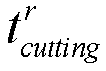
are material cutting times (unit: second) at the rough milling stage and the finish milling stage, respectively; and
taux is auxiliary time consumption (unit: second) of the planar vertical milling process considering the multiple machining stages.
an objective function model for machining energy consumption:
-
In the formula,
Etotal is total energy consumption (unit: Joule) of the planar vertical milling process considering the multiple machining stages;
Estandby is pure standby energy consumption (unit: Joule) of the machine tool in the process of machining preparation and workpiece clamping;
and
are spindle acceleration energy consumptions (unit: Joule) at the rough milling stage and the finish milling stage, respectively;
and
are idle energy consumptions (unit: Joule) at the rough milling stage and the finish milling stage, respectively;
and
are material cutting energy consumptions (unit: Joule) at the rough milling stage and the finish milling stage, respectively; and
Eaux is auxiliary energy consumption (unit: Joule) of the planar vertical milling process considering the multiple machining stages.
an objective function model for machining quality:
-
In the formula,
Ra is surface roughness (unit: µm) of a workpiece;
ka is a correction coefficient, the magnitude of which depends on workpiece material;
nf is a spindle speed (unit: r/min) at the finish milling stage;
ff is a feed (unit: mm/r) at the finish milling stage;
is a milling depth (unit: mm) at the finish milling stage;
is a milling width (unit: mm) at the finish milling stage; and
αa ,
βa ,
γa and
δa are exponents in the formula. Moreover,
αa ,
βa ,
γa and
δa can be obtained by experimental analysis combined with a statistical method.
-
Preferably, the constraint conditions in step 4 include spindle speed constraint, feed constraint, feed speed constraint, milling depth constraint, milling width constraint, machine tool spindle rated power constraint, and tool life constraint.
-
The spindle speed constraint is:
.
-
In the formula,
and
are a lowest rated speed and a highest rated speed (unit: r/min) of a spindle allowed by the machine tool at the rough milling stage, respectively; and
and
are a lowest rated speed and a highest rated speed (unit: r/min) of the spindle allowed by the machine tool at the finish milling stage, respectively.
-
The feed constraint is:
.
-
In the formula,
and
are a minimum feed and a maximum feed (unit: mm/r) allowed by the machine tool at the rough milling stage, respectively; and
and
are a minimum feed and a maximum feed (unit: mm/r) allowed by the machine tool at the finish milling stage, respectively.
-
The feed speed constraint is:
.
-
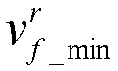
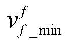
In the formula,
and
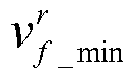
are feed speeds (unit: mm/min) at the rough milling stage and the finish milling stage, respectively;
and
are a minimum feed speed and a maximum feed speed (unit: mm/min) allowed by the machine tool at the rough milling stage, respectively; and
and
are a minimum feed speed and a maximum feed speed (unit: mm/min) allowed by the machine tool at the finish milling stage respectively.
-
The milling depth constraint is:
.
-
In the formula,
and
are a minimum milling depth and a maximum milling depth (unit: mm) allowed at the rough milling stage, respectively; and
and
are a minimum milling depth and a maximum milling depth (unit: mm) allowed at the finish milling stage, respectively.
-
The milling width constraint is:
.
-
In the formula,
and
are a minimum milling width and a maximum milling width (unit: mm) allowed at the rough milling stage, respectively; and
and
are a minimum milling width and a maximum milling width (unit: mm) allowed at the finish milling stage, respectively.
-
The machine tool spindle rated power constraint is:
.
-
In the formula, Pspindle is rotational power (unit: W) of the spindle of the machine tool; Premove is a material removal power (vertical milling power) (unit: W); η is a transmission efficiency of the spindle of the machine tool; and P max is a rated power (unit: W) of a spindle motor of the machine tool.
-
The tool life constraint: Ttoollife ≥ Teconomiclife .
-
In the formula, Ttoollife is a tool life (unit: min); and Teconomiclife is a minimum economic life (unit: min) of the cutting tool.
-
To-be-machined plane dimension feature constraints are:
,
and
;
-
In the formula,
Hp is a height dimension feature (unit: mm) of the to-be-machined plane;
k is the number of milled layers in the whole process of numerical control planar vertical milling;
Wp is a width dimension feature (unit: mm) of the to-be-machined plane;
mr and
mf are the numbers of radial feeds of the cutting tool at the rough milling stage and the finish milling stage, respectively; and
and
are radial machining allowances (unit: mm) of the cutting tool at the rough milling stage and the finish milling stage, respectively.
-
Preferably, the multi-objective optimization mathematical model for planar vertical milling process parameters is:
-
Preferably, a generalized Taylor tool life formula is adopted at the tool life formula:
-
In the formula, CT is a constant term of the tool life formula, the value of which is related to the cutting tool and the workpiece material; n is a spindle speed (unit: r/min); νf is a feed speed (unit: mm/min); f is a feed (unit: mm/r); ap is a milling depth (unit: mm); ae is a milling width (unit: mm); and αt , βt , γt and δt are formula correlation coefficients.
-
Preferably, Step 6 specifically includes:
obtaining, according to the multi-objective optimization mathematical model for planar vertical milling process parameters established in
Step 5, values of corresponding
nr ,
fr ,
,
,
nf ,
ff ,
when
. -
When solving the multi-objective optimization mathematical model, some representative optimization algorithms for processing multi-objective optimization models, such as particle swarm optimization, genetic algorithm and artificial bee colony algorithm, can be adopted. These algorithms are characterized by generating multiple points and searching in multiple directions, very suitable for dealing with process parameter optimization as a multi-objective optimization problem where the optimal solution search space is very complex.
-
The present invention has the following beneficial effects:
The conventional planar vertical milling process parameter optimization is local optimization oriented to a single rough milling process or finish milling process, and machining allowances used in the process of optimization are often machining allowances specified by enterprises. In the present invention, the rough milling stage and the finish milling stage are regarded as a whole for global optimization, so that an optimization result is more applicable. In addition, the present invention considers the life of the cutting tool when dealing with the constraint conditions, so that the optimization result has more practical significance. The present invention solves the problems of low machining efficiency, great energy consumption and poor machining quality caused by improper selection of process parameters in the planar vertical milling process, and the problem that a process parameter optimization result at a single machining stage is not applicable.
BRIEF DESCRIPTION OF THE DRAWINGS
-
- FIG 1 is a schematic diagram of planar vertical milling considering multiple machining stages.
- FIG 2 is a schematic flow chart of a method according to the present invention.
- FIG 3 is a planar vertical milling part drawing considering multiple machining stages in Embodiment 1.
- FIG 3 (a) is a feed path drawing at a rough milling stage of a workpiece, with the upper drawing in FIG 3 (a) being a top view of the workpiece at the rough milling stage and the lower drawing in FIG 3 (a) being the front view of the workpiece at the rough milling stage; and FIG 3 (b) is a feed path drawing at a finish milling stage of the workpiece, with the upper drawing in FIG. 3 (b) being a top view of the workpiece at the finish milling stage and the lower drawing in FIG 3 (b) being a front view of the workpiece at the finish milling stage.
-
In the drawings: 1. cutting tool; 2. feed path; 3. to-be-machined plane; 4. material removed at the rough milling stage; 5. material removed at the finish milling stage.
DETAILED DESCRIPTION
-
The specific embodiments of the present invention are described below in further detail with reference to the accompanying drawings and specific implementations.
-
FIG 1 is a schematic diagram of planar vertical milling considering multiple machining stages. The global planar vertical milling process parameter optimization problem considering multiple machining stages may be described as follows: based on the dimension feature parameters of the to-be-machined plane (length dimension feature
Lp , width dimension feature
Wp and height dimension feature
Hp ), regarding the rough milling stage and the finish milling stage as a whole, the optimal process parameter combination (rough milling spindle speed
nr , rough milling feed
fr , rough milling depth
, rough milling width
, finish milling spindle speed
nf , finish milling feed
f f , finish milling depth
and finish milling width
) is selected for the whole rough milling and finish milling process of a numerical control machine tool, and an appropriate milled layer number
k is planned, so as to ensure that a final machining scheme can comprehensively make three objectives (i.e. machining efficiency, machining energy consumption and machining quality) optimal under the various complex constraint conditions (machine tool capacity, tool life, technical requirements of machining, etc.).
-
According to Embodiment 1, referring to FIGs. 1 to 3, a planar vertical milling parameter optimization and machining performance prediction method considering multiple machining stages includes the following steps:
Step 1: making preparation: A part drawing is checked to identify a to-be-machined plane, dimension feature parameters (length dimension feature Lp , width dimension feature Wp and height dimension feature Hp ) of the to-be-machined plane are analyzed, and the models of a machine tool and a cutting tool are determined, so that a machining process is obtained.
-
Specifically, as shown in FIG 3, the dimensions of a workpiece are 120 mm × 70 mm × 50 mm, and the workpiece is made into a cuboid flat strip with dimensions of 120 mm × 70 mm × 35 mm; and the dimension feature parameters of the to-be-machined plane can be obtained by analysis: Lp = 120mm, Wp = 70mm, and Hp = 15mm.
-
In the present embodiment, an XHK-714F vertical machining center and a W400F-FS coated tungsten steel cutting tool are selected.
-
The specific machining process may be described as follows: during rough milling, the milling cutting tool is first quickly fed to the to-be-machined plane from an initial position, and then goes down for a distance
along the -Z axis, and a spindle is then rotated at a rotational speed
nr , and at the same time, cutting is performed by 140 mm along the +X axis at a cutting feed speed
, completing first feed; subsequently, the milling cutting tool moves along the -Y axis for a distance of cutting width
at the same cutting feed speed
, and then performs cutting by 140 mm along the -X axis at the same cutting feed speed
again, completing second feed; and the above steps are repeated until the milling of the first layer is completed. Subsequently, the milling cutting tool goes down for a
distance along the -Z axis, and the above steps are repeated again until the milling of the second layer, the third layer ... the k-1th layer is completed. After rough milling is completed, the milling tool goes down for a distance
along the -Z axis again to enter the finish milling stage, and at the same time, the feed mode is changed. The spindle is rotated at a rotational speed
nf , climb milling is performed, and at the same time, cutting is performed by 140 mm along the +X axis at a cutting feed speed
, and subsequently, the milling tool is quickly vertically fed upwards for 30 mm along the +Z axis, quickly fed again for 140 mm along the -X axis and quickly fed again for 30 mm along the -Z axis in sequence, completing first feed. Subsequently, the milling tool moves for a distance of cutting width
along the -Y axis at the same cutting feed speed
, and then performs cutting by 140 mm along the -X axis at the same cutting feed speed
again, completing second feed; and the above steps are repeated until the finish milling stage is completed.
-
Step 2: setting optimization variables: spindle speed
nr , feed
fr , milling depth
and milling width
at a rough milling stage and spindle speed
nf , feed
ff , milling depth
and milling width
at a finish milling stage are set as optimization variables.
-
Step 3: selecting optimization objectives: machining efficiency, machining energy consumption and machining quality.
-
Specifically, an objective function model for machining efficiency may be expressed as:
-
In the formula,
Ttotal is total time consumption (unit: second) of the planar vertical milling process considering the multiple machining stages;
tstandby is pure standby time (unit: second) of the machine tool in the process of machining preparation and workpiece clamping;
and
are spindle acceleration times (unit: second) at the rough milling stage and the finish milling stage, respectively;
and
are idle times (unit: second) at the rough milling stage and the finish milling stage, respectively;
and
are material cutting times (unit: second) at the rough milling stage and the finish milling stage, respectively; and
taux is auxiliary time consumption (unit: second) of the planar vertical milling process considering the multiple machining stages.
-
For planar vertical milling considering the multiple machining stages, the pure standby time of the machine tool in the process of machining preparation and workpiece clamping is shared by all the machining stages. In the present embodiment, the pure standby time of the machine tool is tstandby = 1min = 60s.
-
The spindle acceleration time at the rough milling stage is
; and the spindle acceleration time at the finish milling stage is
.
-
The idle time (idling of the spindle and idle feed motion of a feed shaft)
at the rough milling stage is calculated as:
-
In the formula, ┌ ┐represents rounding up;
and
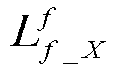
represent feed distances (unit: mm) in the X-axis, Y-axis, and Z-axis directions at the rough milling stage, respectively; and
and
represent feed speeds (unit: mm/min) in the X-axis, Y-axis and Z-axis directions at the rough milling stage, respectively.
-
The idle time (idling of the spindle, idle feed motion of the feed shaft and rapid feed motion of the feed shaft)
at the finish milling stage is calculated as:
-
In the formula,
and
represent feed distances (unit: mm) in the X-axis and Y-axis directions at the finish milling stage, respectively;
and
represent feed speeds (unit: mm/min) in the X-axis and Y-axis directions at the finish milling stage, respectively;
,
and
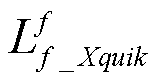
represent rapid feed distances (unit: mm) in the X-axis and Z-axis upward directions and the Z-axis downward direction at the finish milling stage, respectively;
,
and
represent rapid feed speeds (unit: mm/min) in the X-axis and Z-axis upward directions and the Z-axis downward direction at the finish milling stage, respectively; and in addition, in order to reduce programming load for technologists and increase the efficiency of machining, given rapid feed speeds are adopted in the present embodiment, where
and
.
-
The cutting time
at the rough milling stage is calculated as:
-
In the formula,
is a removed material volume (unit: mm
3) at the rough milling stage.
-
The cutting time
at the finish milling stage is calculated as:
-
In the formula,
is a removed material volume (unit: mm
3) at the finish milling stage.
-
For planar vertical milling considering the multiple machining stages, the auxiliary time consumption taux mainly includes two parts: one is automatic tool changing time consumption ttoolchannge in the process of machining; and the other is auxiliary time consumption t toolchange_wear in a case where the tool of the machine tool needs to be changed due to tool wear in the process of machining.
-
In the present embodiment, the automatic tool changing time consumption in the auxiliary time may be calculated as:
-
In the formula, Δpos is the number of tool positions rotated by a tool rest of the machine tool, Δpos = 4, that is, the number of tool positions rotated by the tool rest of the machine tool in the present embodiment is 4.
-
In the auxiliary time, when the tool of the machine tool needs to be changed manually due to tool wear, the consumed time may be calculated as:
-
In the formula, ttoolchange_wear is the time (unit: second) consumed by the manual tool changing required by the machine tool allocated into the machining process of the present embodiment in this patent.
-
In the present embodiment, the objective function model for machining efficiency may be further expressed in detail as:
-
An objective function model for machining energy consumption may be expressed as:
-
In the formula,
Etotal is total energy consumption (unit: Joule) of the planar vertical milling process considering the multiple machining stages;
Estandby is pure standby energy consumption (unit: Joule) of the machine tool in the process of machining preparation and workpiece clamping;
and
are spindle acceleration energy consumptions (unit: Joule) at the rough milling stage and the finish milling stage, respectively;
and
are idle energy consumptions (unit: Joule) at the rough milling stage and the finish milling stage, respectively;
and
are material cutting energy consumptions (unit: Joule) at the rough milling stage and the finish milling stage, respectively; and
Eaux is auxiliary energy consumption (unit: Joule) of the planar vertical milling process considering the multiple machining stages.
-
The energy consumption in the process of numerical control machining is equal to the integration of power over time, so the objective function model for machining energy consumption may be more specifically expressed as:
-
In the formula, Pstandby is standby power of the machine tool (unit: W); Psra is rotational acceleration power of the spindle of the machine tool (unit: W); Pspindle is rotational power of the spindle of the machine tool (unit: W); Pfeed is feed power of the machine tool (unit: W); Premove is material removal power (milling power) (unit: W); Pspraycool is cutting fluid spraying power of the machine tool (unit: W); Prfd is rapid feed power of the machine tool (unit: W); and Ptoolchange is automatic tool changing power of the machine tool (unit: W).
-
In the present embodiment, a power function model of each sub-process in the planar vertical milling process is shown in Table 1.
Table 1: Power Function Model of Each Sub-process in Planar Vertical Milling Process | machining process | power model |
| machine tool standby | |
| cutting fluid spraying | |
| spindle rotation | |
| feed motion | |
| |
| |
| |
| material removal (vertical milling) | |
| spindle rotation acceleration | |
| | |
| rapid feed | |
| |
| | |
| automatic tool changing | |
-
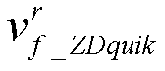
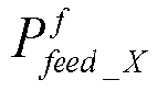
In Table 1, Pstandby_i is an ith collected standby power value (unit: W) of the machine tool; Pspraycool_i is an ith collected cutting fluid spraying power value (including standby power of the machine tool) (unit: W); P feed_X and P feed_Y are X-axis feed power and Y-axis feed power (unit: W) of the numerical control machine tool, respectively; Pfeed_ZU and Pfeed_ZD are Z-axis upward feed power and Z-axis downward feed power (unit: W) of the numerical control machine tool, respectively; vf_X and vf_Y are X-axis feed speed and Y-axis feed speed (unit: mm/min) of the numerical control machine tool, respectively; vf_ZU and vf _ZD are Z-axis upward feed speed and Z-axis downward feed speed (unit: mm/min) of the numerical control machine tool, respectively; Prfd_X and Prfd_Y are X-axis rapid feed power and Y-axis rapid feed power (unit: W) of the numerical control machine tool, respectively; P rfd_X_i is an ith collected X-axis rapid feed power value (including standby power) (unit: W) of the machine tool; P rfd_Y_i is an ith collected Y-axis rapid feed power value (including standby power) (unit: W) of the machine tool; Prfd_ZU and Prfd_ZD are Z-axis upward rapid feed power and Z-axis downward rapid feed power (unit: W) of the numerical control machine tool, respectively; Prfd_ZU_i is an ith collected Z-axis upward rapid feed power value (including standby power) (unit: W) of the machine tool; Prfd_ZD_i is an ith collected Z-axis downward rapid feed power value (including standby power) (unit: W) of the machine tool; and P toolchange_i is an ith collected automatic tool changing power value (including standby power) (unit: W).
-
Further, in the present embodiment, the objective function model for machining energy consumption may be further expressed in detail as:

-
In the formula,
and
are rotational acceleration powers (unit: W) of the spindle at the rough milling stage and the finish milling stage, respectively;
and
are rotational powers (unit: W) of the spindle at the rough milling stage and the finish milling stage, respectively;
and
are X-axis downward feed power, Y-axis downward feed power and Z-axis downward feed power (unit: W) of the machine tool at the rough milling stage;
and
are X-axis feed power and Y-axis feed power (unit: W) of the machine tool at the finish milling stage;
and
are X-axis upward rapid feed power, Z-axis upward rapid feed power and Z-axis downward rapid feed power (unit: W) of the machine tool at the finish milling stage; and
and
are material removal powers (milling powers) (unit: W) at the rough milling stage and the finish milling stage, respectively.
-
The objective function model for machining quality may be expressed as:
-
In the formula,
Ra is surface roughness (unit: µm) of the workpiece;
ka is a correction coefficient, the magnitude of which depends on workpiece material;
nf is a spindle speed (unit: r/min) at the finish milling stage;
ff is a feed (unit: mm/r) at the finish milling stage;
is a milling depth (unit: mm) at the finish milling stage;
is a milling width (unit: mm) at the finish milling stage;
αa ,
βa ,
γa and
δa are exponents in the formula; and
αa ,
βa ,
γa and
δa may be obtained by experimental analysis combined with a statistical method.
-
In the present embodiment, an exponential surface roughness prediction model is adopted, and a function expression is as follows:
-
Step 4: determining constraint conditions; The constraint conditions include spindle speed constraint, feed constraint, feed speed constraint, milling depth constraint, milling width constraint, machine tool spindle rated power constraint, and tool life constraint.
-
The spindle speed constraint is:
.
-
The feed constraint is:
.
-
The feed speed constraint is:
.
-
The milling depth constraint is:
.
-
The milling width constraint is:
.
-
The machine tool spindle rated power constraint is:
.
-
The tool life constraint: Ttoollife ≥ Teconomiclife .
-
To-be-machined plane dimension feature constraints are:
,
and
.
-
For multi-machining stage planar vertical milling combined with rough milling and finish milling, different constraint conditions are often adopted at the rough milling stage and the finish milling stage. During rough milling, priority should be given to increasing productivity, and generally, a large milling depth and feed should be selected, but cutting speed should not be very high. During finishing milling, priority should be given to ensuring the machining precision and surface quality of parts, and a small milling depth and feed and a high cutting speed are often adopted. In addition, combined with the technical specification parameters of the XHK-714F vertical machining center and the recommended range of cutting parameters of the W400F-FS coated tungsten steel tool, the constraint conditions of the machining process in the present embodiment are summarized in Table 2.
Table 2: Constraint Conditions | constraint condition | constraint range |
| | 0 < nr ≤ 3000r/min |
| | 0 < fr ≤ 0.5mm/r |
| recommended range of cutting parameters of tool at rough milling stage | |
| | |
| | |
| | 1000 < nf ≤ 5000r/min |
| | 0 < ff ≤ 0.3mm/r |
| recommended range of cutting parameters of tool at finish milling stage | |
| | |
| | |
| rated power of spindle of machine tool | |
| tool life constraint | Ttoollife > 35 min |
| | |
| to-be-machined plane dimension feature constraint | |
| | |
-
Step 5: establishing a multi-objective optimization mathematical model for planar vertical milling process parameters.
-
The multi-objective optimization mathematical model for planar vertical milling process parameters is:
.
-
Step 6: obtaining, according to the multi-objective optimization mathematical model for planar vertical milling process parameters in step 5, a machining process parameter combination and a machining performance prediction value. When solving the multi-objective optimization mathematical model for planar vertical milling process parameters, some representative optimization algorithms for processing multi-objective optimization models, such as particle swarm optimization, genetic algorithm and artificial bee colony algorithm, can be adopted. These algorithms are characterized by generating multiple points and searching in multiple directions, very suitable for dealing with process parameter optimization as a multi-objective optimization problem where the optimal solution search space is very complex.
-
In the present embodiment, Python language programming is used to solve the model based on the multi-objective particle swarm optimization algorithm. The parameters of the algorithm are set as follows: a particle scale is 100, the number of particle dimensions is 8, the number of iterations is 200, an inertia weight ω is set as 0.9, and acceleration coefficients C1 and C2 are both set as 2. After the parameters are set, the algorithm is called several times to solve the multi-objective optimization mathematical model for planar vertical milling process parameters.
-
The process parameter combination and the machining performance prediction value obtained based on the present invention and a process parameter combination and a machining performance prediction value based on experience are shown in Table 3.
Table 3: Process Parameter Combinations and Machining Performance Prediction Values under Optimal Solution and Empirical Solution | scheme | number of milled layers | nr / nf (r/min) | fr / ff (mm/r) | (mm) | (mm) | Ttotal (s) | Etotal (J) | Ra (µm) |
| optimization scheme | 8-layer rough milling | 1817.5 8 | 0.31 | 1.86 | 6.90 | 1774.6 7 | 1893522.4 5 | 1.32 |
| 1-layer finish milling | 3882.4 4 | 0.11 | 0.12 | 7.34 |
| empirical scheme | 7-layer rough milling | 2000.0 0 | 0.20 | 2.00 | 7.00 | 2030.8 0 | 2102719.1 0 | 1.81 |
| 1-layer finish milling | 3000.0 0 | 0.20 | 1.00 | 7.00 |
-
Step 7: guiding, based on the machining process parameter combination and the machining performance prediction value obtained in step 6, an actual planar vertical milling process.
-
In the present embodiment, the process parameter combination (i.e.
nr =1817.58r/ min ,
fr = 0.31mm/r ,
,
nf = 3882.44r/ min ,
ff=0.11mm/r ,
and
) obtained by the present invention is used for 8-layer rough milling planar machining and 1-layer fine milling planar machining, and a machining time prediction value is 1774.67 seconds, which is 256.13 seconds less than that of the empirical scheme, reduced by 12.61%. A machining energy consumption prediction value is 1893522.45 J, which is 209196.65 J lower than that of the empirical scheme, reduced by 9.95%. A workpiece surface roughness prediction value is 1.32 µm, which may be 0.49 µm lower than that of the empirical scheme, reduced by 27.07%. Therefore, better machining performance is achieved.
-
Certainly, the above descriptions are merely preferred embodiments of the present disclosure. The present disclosure is not limited to the above embodiments listed. It should be noted that, all equivalent replacements and obvious variations made by any person skilled in the art under the teaching of the specification fall within the essential scope of the specification and shall be protected by the present disclosure.






















 Step 3: selecting optimization objectives: machining efficiency, machining energy consumption and machining quality; wherein comprising:an objective function model for machining efficiency:


 an objective function model for machining energy consumption:


 an objective function model for machining quality:

 Step 4: determining constraint conditions;the constraint conditions comprise spindle speed constraint, feed constraint, feed speed constraint, milling depth constraint, milling width constraint, machine tool spindle rated power constraint, and tool life constraint;the spindle speed constraint is:
 in the formula,


 the feed constraint is:
 in the formula,


 the feed speed constraint is:
 in the formula,


 the milling depth constraint is:
 in the formula,


 the milling width constraint is:
 in the formula,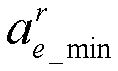


 the machine tool spindle rated power constraint is:
 in the formula, Pspindle is rotational power (unit: W) of the spindle of the machine tool; Premove is a material removal power (unit: W); η is a transmission efficiency of the spindle of the machine tool; and P max is a rated power (unit: W) of a spindle motor of the machine tool;the tool life constraint: Ttoollife ≥ Teconomiclife ;in the formula, Ttoollife is a tool life (unit: min); and Teconomiclife is a minimum economic life (unit: min) of the cutting tool;to-be-machined plane dimension feature constraints are:
 in the formula, HP is a height dimension feature (unit: mm) of the to-be-machined plane; k is the number of milled layers in the whole process of numerical control planar vertical milling; Wp is a width dimension feature (unit: mm) of the to-be-machined plane; mr and mf are the numbers of radial feeds of the cutting tool at the rough milling stage and the finish milling stage, respectively; and
 Step 5: establishing a multi-objective optimization mathematical model for planar vertical milling process parameters;
 Step 6: obtaining, according to the multi-objective optimization mathematical model for planar vertical milling process parameters in step 5, a machining process parameter combination and a machining performance prediction value;Step 7: guiding, based on the machining process parameter combination and the machining performance prediction value obtained in step 6, an actual planar vertical milling process.


