EP4571133A1 - Nut retainer assemblies for blind fastener systems, blind fastener systems and methods for assembling nut retainer assemblies on substrates - Google Patents
Nut retainer assemblies for blind fastener systems, blind fastener systems and methods for assembling nut retainer assemblies on substrates Download PDFInfo
- Publication number
- EP4571133A1 EP4571133A1 EP24217464.7A EP24217464A EP4571133A1 EP 4571133 A1 EP4571133 A1 EP 4571133A1 EP 24217464 A EP24217464 A EP 24217464A EP 4571133 A1 EP4571133 A1 EP 4571133A1
- Authority
- EP
- European Patent Office
- Prior art keywords
- nut
- retainer
- washer
- fastener
- retainer assembly
- Prior art date
- Legal status (The legal status is an assumption and is not a legal conclusion. Google has not performed a legal analysis and makes no representation as to the accuracy of the status listed.)
- Pending
Links
Images







Classifications
-
- F—MECHANICAL ENGINEERING; LIGHTING; HEATING; WEAPONS; BLASTING
- F16—ENGINEERING ELEMENTS AND UNITS; GENERAL MEASURES FOR PRODUCING AND MAINTAINING EFFECTIVE FUNCTIONING OF MACHINES OR INSTALLATIONS; THERMAL INSULATION IN GENERAL
- F16B—DEVICES FOR FASTENING OR SECURING CONSTRUCTIONAL ELEMENTS OR MACHINE PARTS TOGETHER, e.g. NAILS, BOLTS, CIRCLIPS, CLAMPS, CLIPS OR WEDGES; JOINTS OR JOINTING
- F16B37/00—Nuts or like thread-engaging members
- F16B37/04—Devices for fastening nuts to surfaces, e.g. sheets, plates
- F16B37/044—Nut cages
-
- F—MECHANICAL ENGINEERING; LIGHTING; HEATING; WEAPONS; BLASTING
- F16—ENGINEERING ELEMENTS AND UNITS; GENERAL MEASURES FOR PRODUCING AND MAINTAINING EFFECTIVE FUNCTIONING OF MACHINES OR INSTALLATIONS; THERMAL INSULATION IN GENERAL
- F16B—DEVICES FOR FASTENING OR SECURING CONSTRUCTIONAL ELEMENTS OR MACHINE PARTS TOGETHER, e.g. NAILS, BOLTS, CIRCLIPS, CLAMPS, CLIPS OR WEDGES; JOINTS OR JOINTING
- F16B37/00—Nuts or like thread-engaging members
- F16B37/04—Devices for fastening nuts to surfaces, e.g. sheets, plates
-
- F—MECHANICAL ENGINEERING; LIGHTING; HEATING; WEAPONS; BLASTING
- F16—ENGINEERING ELEMENTS AND UNITS; GENERAL MEASURES FOR PRODUCING AND MAINTAINING EFFECTIVE FUNCTIONING OF MACHINES OR INSTALLATIONS; THERMAL INSULATION IN GENERAL
- F16B—DEVICES FOR FASTENING OR SECURING CONSTRUCTIONAL ELEMENTS OR MACHINE PARTS TOGETHER, e.g. NAILS, BOLTS, CIRCLIPS, CLAMPS, CLIPS OR WEDGES; JOINTS OR JOINTING
- F16B11/00—Connecting constructional elements or machine parts by sticking or pressing them together, e.g. cold pressure welding
- F16B11/006—Connecting constructional elements or machine parts by sticking or pressing them together, e.g. cold pressure welding by gluing
-
- F—MECHANICAL ENGINEERING; LIGHTING; HEATING; WEAPONS; BLASTING
- F16—ENGINEERING ELEMENTS AND UNITS; GENERAL MEASURES FOR PRODUCING AND MAINTAINING EFFECTIVE FUNCTIONING OF MACHINES OR INSTALLATIONS; THERMAL INSULATION IN GENERAL
- F16B—DEVICES FOR FASTENING OR SECURING CONSTRUCTIONAL ELEMENTS OR MACHINE PARTS TOGETHER, e.g. NAILS, BOLTS, CIRCLIPS, CLAMPS, CLIPS OR WEDGES; JOINTS OR JOINTING
- F16B37/00—Nuts or like thread-engaging members
- F16B37/14—Cap nuts; Nut caps or bolt caps
-
- F—MECHANICAL ENGINEERING; LIGHTING; HEATING; WEAPONS; BLASTING
- F16—ENGINEERING ELEMENTS AND UNITS; GENERAL MEASURES FOR PRODUCING AND MAINTAINING EFFECTIVE FUNCTIONING OF MACHINES OR INSTALLATIONS; THERMAL INSULATION IN GENERAL
- F16B—DEVICES FOR FASTENING OR SECURING CONSTRUCTIONAL ELEMENTS OR MACHINE PARTS TOGETHER, e.g. NAILS, BOLTS, CIRCLIPS, CLAMPS, CLIPS OR WEDGES; JOINTS OR JOINTING
- F16B43/00—Washers or equivalent devices; Other devices for supporting bolt-heads or nuts
Definitions
- the present disclosure relates generally to nut retainer assemblies for blind fastener systems and, particularly, to nut retainer assemblies suitable for bonding to a substrate and used to retain a fastener nut for subsequent engagement by a fastener bolt.
- the retained fastener nut and the fastener bolt being used to join multiple substrates together.
- Various examples of the nut retainer assemblies and blind fastener systems are described.
- Various methods for assembling nut retainer assemblies on substrates are also described.
- Various configurations of the nut retainer assemblies provide a pre-installed fastener nut on a blind side of one substrate for one-sided installation of the fastener bolt from a working side of another substrate.
- Future airplane wing box architectures are getting smaller, which generates confined space and the need for a different fastening system that enables assembly from the outer mold line of the wing (e.g., skin/shear ties and skin/spar).
- the traditional nut plate styles are not applicable to the need for fuel tank and electromagnetic effect requirements.
- Current designs for nut retainers and one-sided fastener systems either are not able to take the required torque needed in high strength applications and or require the nut retainer to be mechanically attached to the substructure for them to work. Additionally, the current two-piece fastener systems far outperform any one-sided fastener system.
- nut retainer assemblies for blind fastener systems, blind fastener systems and methods for assembling nut retainer assemblies on substrates.
- the following is a non-exhaustive list of examples, which may or may not be claimed, of the subject matter according to the present disclosure.
- a nut retainer assembly for a blind fastener system includes a bond washer and a nut retainer.
- the bond washer defines a longitudinal axis extending from a proximal washer end to a distal washer end.
- the bond washer includes a flange portion, a washer coupling portion, a first interior surface, a second interior surface and a bonding surface.
- the flange portion is at the proximal washer end.
- the washer coupling portion extends from the flange portion to the distal washer end.
- the first interior surface is associated with the flange portion and defines a first aperture.
- the second interior surface is associated with the washer coupling portion and includes internal threads.
- the bonding surface is associated with the flange portion at the proximal washer end.
- the nut retainer defines a proximal retainer end and a distal retainer end along the longitudinal axis and extending the longitudinal axis from the distal washer end to the distal retainer end.
- the nut retainer includes a retainer coupling portion, a nut retaining portion, a first exterior surface and a third interior surface.
- the retainer coupling portion at the proximal retainer end.
- the nut retaining portion extends from the retainer coupling portion to the distal retainer end.
- the first exterior surface is associated with the retainer coupling portion.
- the third interior surface is associated with the retainer coupling portion and the nut retaining portion.
- the third interior surface defines a central opening extending from the proximal retainer end to the distal retainer end.
- another nut retainer assembly for a blind fastener system includes a nut retainer.
- the nut retainer defines a longitudinal axis extending from a proximal retainer end to a distal retainer end.
- the nut retainer includes a flange portion, a nut retaining portion, a sixth interior surface and a bonding surface.
- the flange portion at the proximal retainer end.
- the nut retaining portion extends from the flange portion to the distal retainer end.
- the sixth interior surface is associated with the flange portion and the nut retaining portion.
- the sixth interior surface defines a central opening extending from the proximal retainer end to the distal retainer end.
- a blind fastener system includes a fastener bolt, a first substrate, a second substrate, a fastener nut and a nut retainer assembly.
- the fastener bolt includes a head portion, a shank portion and a threaded portion.
- the first substrate includes a first through hole sized to provide a first clearance fit for the fastener bolt and defines a first clamping surface to receive the fastener bolt.
- the first substrate also defines a first working surface.
- the second substrate includes a second through hole sized to provide a second clearance fit for the fastener bolt and defining a second clamping surface facing the first clamping surface.
- the second substrate also includes a second working surface to receive the fastener bolt.
- the fastener nut is for placement on the first working surface of the first substrate over the first through bore.
- the fastener nut includes a threaded bore.
- the nut retainer assembly defines a central opening sized and shaped to fit over and retain the fastener nut on the first working surface of the first substrate.
- the nut retainer assembly includes a bonding surface bordering the central opening.
- the bonding surface is bonded to the first working surface of the first substrate such that the second through hole of the second substrate, the first through hole of the first substrate and the threaded bore of the fastener nut provide for insertion of the fastener bolt and threaded engagement of the threaded portion of the fastener bolt with the threaded bore of the fastener nut.
- a method for assembling a nut retainer assembly on a substrate includes: (1) predrilling a hole through the substrate at a predetermined location for the nut retainer assembly; (2) applying an adhesive to at least a portion of a bonding surface on a bond washer of the nut retainer assembly; (3) bonding the bond washer over the hole in the substrate using the adhesive such that the hole is centered in relation to a first aperture through the bond washer; (4) positioning a fastener nut over the bond washer; (5) positioning a nut retainer with a central opening over the fastener nut and the bond washer, the nut retainer having external threads for engagement with internal threads of the bond washer, the central opening providing a clearance fit for the fastener nut; and (6) turning the nut retainer into threaded engagement with the bond washer to retain the fastener nut within the nut retainer assembly on the substrate.
- another method for assembling a nut retainer assembly on a substrate includes: (1) predrilling a hole through the substrate at a predetermined location for the nut retainer assembly; (2) applying an adhesive to at least a portion of a bonding surface on a nut retainer of the nut retainer assembly; (3) positioning a fastener nut in a central opening of the nut retainer, the central opening providing a clearance fit for the fastener nut; and (4) bonding the nut retainer over the hole in the substrate using the adhesive such that the hole is centered in relation to the central opening and the fastener nut is retained within the nut retainer assembly on the substrate.
- the various examples of nut retainer assemblies and blind fastener systems disclosed herein provide a high torque bonded nut retainer assembly for high strength one-sided fastener applications.
- Various configurations allow existing fasteners (e.g., fastener bolts and fastener nuts) to be installed in a one-sided application without damage and/or modifying the underlying substructure.
- the nut retainer assemblies can be used in locations where it is not desirable to add additional retaining features and/or damage the substrate material for the nut to be locked in place.
- the nut retainer assemblies utilize bond strength to counteract the torque of the fastener.
- the nut retainer assemblies and blind fastener systems can be used with off-the-shelf fastening standards with known characteristics and requirements. This eliminates or reduces the need to test the joint configuration.
- the various examples of nut retainer assemblies rely on a bonded surface to retain the nut until the fastener has sufficient clamp up force with the substructure. Once the sufficient clamp up force is achieved, the fastener nut takes the compressive load until a final torque is achieved.
- the bonded surface area is between a bonding surface on the nut retainer assembly and a working surface of a substate. The bond needs to be held just long enough such that the nut can clamp up on the surface. If there is not sufficient bonding area, the nut cannot clamp up. Torque values tested met or exceeded head side drive torque limits for brass, aluminum, titanium, A286, 300-series corrosion-resistant steel and Inconel/nickel alloy 718 fasteners with nuts.
- the nut retainer assemblies can be used in applications requiring a structural one-sided fastener and, particularly, in locations where there is insufficient access to install a two-part fastener system.
- the bonded nut retainers can be preinstalled on the substrate, then head side drive fasteners can be installed from an exterior working surface of another substrate.
- Fig. 1 discloses an example of the nut retainer assembly 100.
- Fig. 2 discloses an example of the blind fastener system 200.
- Fig. 3 shows a cross-sectional side view of a portion of an example of a bond washer 102 for the nut retainer assembly 100 of Fig. 1 .
- Fig. 4 shows a cross-sectional side view of the nut retainer assembly 100 of Fig. 1 positioned on a working surface 202 of a substrate 204 at a predetermined location 402 for a hole 404 through the substrate 204.
- Fig. 1 discloses an example of the nut retainer assembly 100.
- Fig. 2 discloses an example of the blind fastener system 200.
- Fig. 3 shows a cross-sectional side view of a portion of an example of a bond washer 102 for the nut retainer assembly 100 of Fig. 1 .
- Fig. 4 shows a cross-sectional side view of the nut retainer assembly 100 of Fig. 1
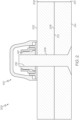
- FIG. 5 shows a cross-sectional side view of the nut retainer assembly 100 of Fig. 1 with a fastener nut 140 retained therein.
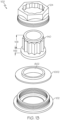
- Fig. 6 shows an exploded view of another example of the nut retainer assembly 100 of Fig. 1 with a grip retainer extension 602 and a grip extension washer 604.
- Fig. 7 shows a cross-sectional side view of the nut retainer assembly 100 of Fig. 1 with a nonconductive cap 702 and a fastener nut 140 retained therein.
- Fig. 8 show an exploded view of yet another example of a nut retainer assembly 100 that includes a seal washer 802.
- Fig. 9 shows a cross-sectional side view of the nut retainer assembly 100 of Fig. 8 with a nonconductive cap 702 and a fastener nut 140 retained therein.
- Fig. 10 shows an exploded view of still another example of a nut retainer assembly 100 that includes a retention washer 1002.
- Fig. 11 shows a cross-sectional side view of the nut retainer assembly 100 of Fig. 10 with a nonconductive cap 702 and a fastener nut 140 retained therein.
- Fig. 9 shows a cross-sectional side view of the nut retainer assembly 100 of Fig. 8 with a nonconductive cap 702 and a fastener nut 140 retained therein.
- Fig. 10 shows an exploded view of still another example of a nut retainer assembly 100 that includes a retention washer 1002.
- Fig. 11 shows a cross-sectional
- FIG. 12 shows a cross-sectional side view of portions of examples of a bond washer 102, a retention washer 1002 and a nut retainer 124 for the nut retainer assembly 100 of Fig. 10 .
- Fig. 13 shows an exploded view of still yet another example of a nut retainer assembly 100 that includes a seal washer 802 and a retention washer 1002.
- Fig. 14 shows a cross-sectional side view of the nut retainer assembly 100 of Fig. 13 with a nonconductive cap 702 and a fastener nut 140 retained therein.
- a nut retainer assembly 100 for a blind fastener system 200 includes a bond washer 102 and a nut retainer 124.
- the bond washer 102 defines a longitudinal axis 104 extending from a proximal washer end 106 to a distal washer end 108.
- the bond washer 102 includes a flange portion 110, a washer coupling portion 112, a first interior surface 114, a second interior surface 118 and a bonding surface 122.
- the flange portion 110 is at the proximal washer end 106.
- the washer coupling portion 112 extends from the flange portion 110 to the distal washer end 108.
- the first interior surface 114 is associated with the flange portion 110.
- the first interior surface 114 defines a first aperture 116.
- the second interior surface 118 is associated with the washer coupling portion 112.
- the second interior surface 118 includes internal threads 120.
- the bonding surface 122 is associated with the flange portion 110 at the proximal washer end 106.
- the nut retainer 124 defines a proximal retainer end 126 and a distal retainer end 128 along the longitudinal axis 104 and extends the longitudinal axis 104 from the distal washer end 108 to the distal retainer end 128.
- the nut retainer 124 includes a retainer coupling portion 130, a nut retaining portion 132, a first exterior surface 134 and a third interior surface 136.
- the retainer coupling portion 130 is at the proximal retainer end 126.
- the nut retaining portion 132 extends from the retainer coupling portion 130 to the distal retainer end 128.
- the first exterior surface 134 is associated with the retainer coupling portion 130.
- the third interior surface 136 is associated with the retainer coupling portion 130 and the nut retaining portion 132.
- the third interior surface 136 defines a central opening 138 extending from the proximal retainer end 126 to the distal retainer end 128.
- the bond washer 102 includes a metal material.
- the metal material includes titanium, tungsten carbide, tungsten, high-strength corrosion-resistant steel, stainless steel or any other suitable metal material in any suitable combination.
- the nut retainer 124 includes a metal material.
- the metal material includes titanium, tungsten carbide, tungsten, high-strength corrosion-resistant steel, stainless steel or any other suitable metal material in any suitable combination.
- the bond washer 102 is configured to be bonded to a working surface 202 of a substrate 204 using an adhesive 306.
- the bond washer 102 being positioned over a predetermined location 402 for a hole 404 through which a fastener bolt 206 is subsequently inserted from a clamping surface 208 of the substrate 204 for engagement with a fastener nut 140 retained by the nut retainer assembly 100.
- the adhesive 306 includes a BAC1010 adhesive, a type 111 adhesive, an EA 9394 adhesive, a BAC5010 adhesive, a type 106 adhesive, a type 70 adhesive, a type 117 adhesive or any other suitable adhesive in any suitable combination.
- the hole 404 includes pilot hole 406 predrilled at the predetermined location 402 in conjunction with the bond washer 102 being bonded to the working surface 202 of the substrate 204.
- the hole 404 includes a full-sized hole 408 predrilled at the predetermined location 402 in conjunction with the bond washer 102 being bonded to the working surface 202 of the substrate 204.
- the third interior surface 136 associated with the retainer coupling portion 130 and the nut retaining portion 132 is sized and shaped to fit over a fastener nut 140 between the nut retainer 124 and the bond washer 102.
- the first exterior surface 134 associated with the retainer coupling portion 130 is threaded for engagement with the internal threads 120 in the washer coupling portion 112 to retain the fastener nut 140 between the nut retainer 124 and the bond washer 102.
- the nut retainer 124 also includes a second exterior surface 142 associated with the nut retaining portion 132 extending from the retainer coupling portion 130 to the distal retainer end 128.
- the second exterior surface 142 associated with the nut retaining portion 132 is sized and shaped to provide a torquing feature 144 proximate the distal retainer end 128 for securing the nut retainer 124 within the nut retainer assembly 100 and for removing the nut retainer 124 from the nut retainer assembly 100.
- the torquing feature 144 includes a 4-point torquing feature, a 6-point torquing feature, a 12-point torquing feature or any other suitable shape for the torquing feature 148.
- the third interior surface 136 associated with the retainer coupling portion 130 and the nut retaining portion 132 of the nut retainer 124 is sized and shaped to provide a first horizontal float 502 between a compressive feature 146 of the fastener nut 140 and the nut retainer 124 and a second horizontal float 503 between a torquing feature 148 of the fastener nut 140 and the nut retainer 124.
- the first horizontal float 502 includes 20 thousandths of an inch, 18 thousandths to 22 thousandths of an inch, 15 thousandths to 25 thousandths of an inch or any other suitable dimension or range of dimensions for the first horizontal float 502.
- the second horizontal float 503 includes 9 thousandths of an inch, 7 thousandths to 11 thousandths of an inch, 5 thousandths to 13 thousandths of an inch or any other suitable dimension or range of dimensions for the second horizontal float 503.
- the third interior surface 136 associated with the retainer coupling portion 130 is sized and shaped to provide a vertical float 504 between a compressive feature 146 of the fastener nut 140 and the nut retainer 124.
- the vertical float 504 includes five thousandths of an inch, four thousandths to six thousandths of an inch, three thousandths to seven thousandths of an inch or any other suitable dimension or range of dimensions for the vertical float 504.
- a portion of the central opening 138 proximate the distal retainer end 128 is sized and shaped to provide a clearance fit for a torquing feature 148 of the fastener nut 140 while preventing the fastener nut 140 from turning when it is retained between the nut retainer 124 and the bond washer 102.
- the portion of the central opening 138 proximate the distal retainer end 128 is sized to fit the torquing feature 148 a 1/4 inch fastener nut, a 5/16 inch fastener nut, a 3/8 inch fastener nut, a 7/16 inch fastener nut, a 1/2 inch fastener nut, a 9/16 inch fastener nut, a 5/8 inch fastener nut, an 11/16 inch fastener nut, a 3/4 inch fastener nut, a 13/16 inch fastener nut, a 7/8 inch fastener nut, a 15/16 inch fastener nut, a one inch fastener nut or any other suitable dimension for the fastener nut 140.
- the portion of the central opening 138 proximate the distal retainer end 128 is sized to fit the torquing feature 148 of a 6 mm fastener nut, a 8 mm fastener nut, a 9 mm fastener nut, a 10 mm fastener nut, an 11 mm fastener nut, a 12 mm fastener nut, a 13 mm fastener nut, a 14 mm fastener nut, a 15 mm fastener nut, a 16 mm fastener nut, a 17 mm fastener nut, a 18 mm fastener nut, a 19 mm fastener nut, a 20 mm fastener nut or any other suitable dimension for the fastener nut 140.
- the portion of the central opening 138 proximate the distal retainer end 128 is shaped to fit the torquing feature 148 of a 4-point fastener nut, a 6-point fastener nut, a 12-point fastener nut or any other suitable shape for the torquing feature 148.
- the nut retainer 124 also includes a grip retainer extension 602 between the proximal retainer end 126 and the distal retainer end 128.
- the grip retainer extension 602 enables the nut retainer assembly 100 to be used for a fastener bolt 206 with a longer grip length.
- the nut retainer assembly 100 also includes a grip extension washer 604 disposed within the central opening 138 at the proximal retainer end 126 between a fastener nut 140 retained within the nut retainer 124 and the bond washer 102.
- the grip extension washer 604 enables the nut retainer assembly 100 to be used for a fastener bolt 206 with a longer grip length.
- the nut retainer assembly 100 also includes a nonconductive cap 702 to protect an operational environment within which the nut retainer assembly 100 is used from electromagnetic emissions and electrical sparks discharged by metal components 102, 124 of the nut retainer assembly 100 and metal fasteners 140, 206 associated therewith.
- a third exterior surface 704 associated with the washer coupling portion 112 is configured to receive and engage with the nonconductive cap 702.
- a fourth interior surface 706 associated with the nonconductive cap 702 and the third exterior surface 704 of the washer coupling portion 112 are threaded for engagement of the nonconductive cap 702 on the bond washer 102.
- a fourth interior surface 706 associated with the nonconductive cap 702 and the third exterior surface 704 of the washer coupling portion 112 are configured for twist-lock engagement.
- the nonconductive cap 702 is transparent to permit internal inspection after the nut retainer assembly 100 is assembled with a fastener nut 140 retained therein.
- the nonconductive cap 702 includes a transparent polymer material.
- the transparent polymer material includes a transparent nylon material, a nylon TMDT material, a nylon 6-3-T material, a trimethylhexamethylenediamine material, a dimethyl terephthalate material or any other suitable transparent polymer material in any suitable combination.
- the nonconductive cap 702 includes a port 708 for receipt of a nonconductive sealant between a fourth interior surface 706 associated with the nonconductive cap 702 and the third exterior surface 704 associated with the washer coupling portion 112 after the nut retainer assembly 100 is assembled with a fastener nut 140 retained therein to enhance protection of the operational environment from electromagnetic emissions and electrical sparks discharged by metal components 102, 124 of the nut retainer assembly 100 and metal fasteners 140, 206 associated therewith.
- the retainer coupling portion 130 includes external threads 150 for engagement with the internal threads 120 in the washer coupling portion 112 to retain a fastener nut 140 between the nut retainer 124 and the bond washer 102.
- the proximal retainer end 126 sits on the flange portion 110 of the bond washer 102 and at least a portion of a compressive feature 146 of the fastener nut 140 sits on the flange portion 110.
- the bonding surface 122 of the bond washer 102 includes a recessed area 302 along a peripheral portion 304 of the bonding surface 122 for receipt of an adhesive 306 and a contact area 308 extending from the recessed area 302 to the first aperture 116 of the flange portion 110.
- the adhesive 306 includes a BAC1010 adhesive, a type 111 adhesive, an EA 9394 adhesive, a BAC5010 adhesive, a type 106 adhesive, a type 70 adhesive, a type 117 adhesive or any other suitable adhesive in any suitable combination.
- the first aperture 116 in the flange portion 110 of the bond washer 102 is sized to provide a clearance fit for a fastener bolt 206 associated with the fastener nut 140.
- the third interior surface 136 associated with the retainer coupling portion 130 defines a second aperture 506 wider than the first aperture 116 and sized to provide a clearance fit for the fastener nut 140 at the proximal retainer end 126.
- the third interior surface 136 associated with the retainer coupling portion 130 defines a second aperture 506 wider than the first aperture 116 and sized to provide a clearance fit for the fastener nut 140 at the proximal retainer end 126.
- the nut retainer assembly 100 also includes a seal washer 802 disposed within the first aperture 116 and affixed to the first interior surface 114 associated with the flange portion 110 of the bond washer 102 after the nut retainer 124 and the bond washer 102 are assembled with a fastener nut 140 retained therein.
- the first aperture 116 is sized to provide an interference fit for the seal washer 802.
- the seal washer 802 defines a third aperture 804 sized to provide an interference fit for a fastener bolt 206 associated with the fastener nut 140.
- the seal washer 802 includes a nonconductive polymer material.
- the nonconductive polymer material includes a polyether ether ketone material, a polyaryle ether ketone material, a polyether ketone material, a polyether ketone ether ketone ketone material, a polyetherimide material or any other suitable nonconductive polymer material.
- the seal washer 802 enhances protection of an operational environment within which the nut retainer assembly 100 is used from electromagnetic emissions and electrical sparks discharged by metal components 102, 124 of the nut retainer assembly 100 and metal fasteners 140, 206 associated therewith.
- the seal washer 802 acts as a fluid barrier in relation to the blind fastener system 200. In still yet another further example, the seal washer 802 extends from the first interior surface 114 associated with the flange portion 110 of the bond washer 102 to at least part of a non-threaded bore 806 in the compressive feature 146 of the fastener nut 140.
- the washer coupling portion 112 defines a fourth aperture 152 wider than the first aperture 116 in the flange portion 110 of the bond washer 102 thereby defining an inner portion 1102 of the flange portion 110 extending from the washer coupling portion 112 to the first aperture 116 and an outer portion 1104 extending from the washer coupling portion 112 to a fourth exterior surface 1106 associated with the flange portion 110.
- the nut retainer assembly 100 also includes a retention washer 1002 with a fifth interior surface 1004, a lip portion 1108 and a nut support portion 1110.
- the fifth interior surface 1004 defining a fifth aperture 1112.
- the lip portion 1108 having a first thickness 1202.
- the nut support portion 1110 having a second thickness 1204 greater than the first thickness 1202.
- the retention washer 1002 disposed within the fourth aperture 152 of the washer coupling portion 112 with the lip portion 1108 overlaying the inner portion 1102 of the flange portion 110 for the bond washer 102 and the nut support portion 1110 extending into the first aperture 116 of the flange portion 110.
- the retention washer 1002 includes a metal material.
- the metal material includes titanium, tungsten carbide, tungsten, high-strength corrosion-resistant steel, stainless steel or any other suitable metal material in any suitable combination.
- the first aperture 116 in the flange portion 110 of the bond washer 102 is sized to provide a clearance fit for the nut support portion 1110 of the retention washer 1002.
- the fourth aperture 152 of the washer coupling portion 112 is sized to provide a clearance fit for the lip portion 1108 of the retention washer 1002.
- the fifth aperture 1112 of the retention washer 1002 is sized to provide a clearance fit for a fastener bolt 206 associated with a fastener nut 140.
- the third interior surface 136 associated with the retainer coupling portion 130 and the nut retaining portion 132 of the nut retainer 124 is sized and shaped to fit over a fastener nut 140 between the nut retainer 124 and the retention washer 1002.
- the retainer coupling portion 130 includes external threads 150 for engagement with the internal threads 120 in the washer coupling portion 112 to retain a fastener nut 140 between the nut retainer 124 and the retention washer 1002.
- the proximal retainer end 126 sits on the lip portion 1108 of the retention washer 1002
- at least a portion of a compressive feature 146 of the fastener nut 140 sits on the nut support portion 1110 of the retention washer 1002
- the nut support portion 1110 of the retention washer 1002 extends beyond the first aperture 116 in the flange portion 110 of the bond washer 102 to provide a contact surface 1206 configured to sit on a working surface 202 of a substrate 204 prior to the bond washer 102.
- the nut retainer 124 also includes a grip retainer extension 602 between the proximal retainer end 126 and the distal retainer end 128.
- the nut retainer assembly 100 also includes a grip extension washer 604 disposed within the central opening 138 at the proximal retainer end 126 between a fastener nut 140 retained within the nut retainer 124 and the retention washer 1002.
- the nut retainer assembly 100 also includes a seal washer 802 disposed within the fifth aperture 1112 of the retention washer 1002 and affixed to the fifth interior surface 1004 associated with the retention washer 1002 after the nut retainer 124, the retention washer 1002 and the bond washer 102 are assembled with a fastener nut 140 retained therein.
- the fifth aperture 1112 of the retention washer 1002 is sized to provide an interference fit for the seal washer 802 and the seal washer 802 defines a third aperture 804 sized to provide an interference fit for a fastener bolt 206 associated with the fastener nut 140.
- the seal washer 802 includes a nonconductive polymer material.
- the nonconductive polymer material includes a polyether ether ketone material, a polyaryle ether ketone material, a polyether ketone material, a polyether ketone ether ketone ketone material, a polyetherimide material or any other suitable nonconductive polymer material in any suitable combination.
- the seal washer 802 enhances protection of an operational environment within which the nut retainer assembly 100 is used from electromagnetic emissions and electrical sparks discharged by metal components 102, 124, 1002 of the nut retainer assembly 100 and metal fasteners 140, 206 associated therewith.
- the seal washer 802 acts as a fluid barrier in relation to the blind fastener system 200.
- the seal washer 802 extends from the fifth interior surface 1004 associated with the retention washer 1002 to at least part of a non-threaded bore 806 in a compressive feature 146 of the fastener nut 140.
- Fig. 15 discloses an example of the nut retainer assembly 100.
- Fig. 16 shows a cross-sectional side view of the nut retainer assembly 100 of Fig. 15 with a fastener nut 140 retained therein.
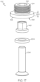
- Fig. 17 shows an exploded view of another example of the nut retainer assembly 100 of Fig. 1 with a grip retainer extension 602 and a grip extension washer 604.
- Fig. 18 shows a cross-sectional side view of the nut retainer assembly 100 of Fig. 15 with a nonconductive cap 702 and a fastener nut 140 retained therein.
- a nut retainer assembly 100 for a blind fastener system 200 includes a nut retainer 124 defining a longitudinal axis 104 extending from a proximal retainer end 126 to a distal retainer end 128.
- the nut retainer 124 includes a flange portion 110, a nut retaining portion 132, a sixth interior surface 1502 and a bonding surface 122.
- the flange portion 110 at the proximal retainer end 126.
- the nut retaining portion 132 extending from the flange portion 110 to the distal retainer end 128.
- the sixth interior surface 1502 is associated with the flange portion 110 and the nut retaining portion 132.
- the sixth interior surface 1502 defines a central opening 138 extending from the proximal retainer end 126 to the distal retainer end 128.
- the bonding surface 122 associated with the flange portion 110 at the proximal retainer end 126.
- the nut retainer 124 includes a metal material.
- the metal material includes titanium, tungsten carbide, tungsten, high-strength corrosion-resistant steel, stainless steel or any other suitable metal material in any suitable combination.
- the nut retainer 124 is configured to be bonded to a working surface 202 of a substrate 204 using an adhesive 306.
- the nut retainer 124 being positioned over a fastener nut 140 at a predetermined location 402 for a hole 404 through which a fastener bolt 206 is subsequently inserted from a clamping surface 208 of the substrate 204 for engagement with the fastener nut 140 retained between the nut retainer 124 and the working surface 202.
- the adhesive 306 includes a BAC1010 adhesive, a type 111 adhesive, an EA 9394 adhesive, a BAC5010 adhesive, a type 106 adhesive, a type 70 adhesive, a type 117 adhesive or any other suitable adhesive in any suitable combination.
- the hole 404 includes a pilot hole 406 predrilled at the predetermined location 402 in conjunction with the nut retainer 124 being bonded to the working surface 202 of the substrate 204.
- the hole 404 includes a full-sized hole 408 predrilled at the predetermined location 402 in conjunction with the nut retainer 124 being bonded to the working surface 202 of the substrate 204.
- the sixth interior surface 1502 associated with the flange portion 110 and the nut retaining portion 132 is sized and shaped to fit over a fastener nut 140 between the nut retainer 124 and a working surface 202 of a substrate 204.
- the sixth interior surface 1502 associated with the flange portion 110 and the nut retaining portion 132 is sized and shaped to provide a first horizontal float 502 between a compressive feature 146 of the fastener nut 140 and the nut retainer 124 and a second horizontal float 503 between a torquing feature 148 of the fastener nut 140 and the nut retainer 124.
- the first horizontal float 502 includes 20 thousandths of an inch, 18 thousandths to 22 thousandths of an inch, 15 thousandths to 25 thousandths of an inch or any other suitable dimension for the first horizontal float 502.
- the second horizontal float 503 includes 9 thousandths of an inch, 7 thousandths to 11 thousandths of an inch, 5 thousandths to 13 thousandths of an inch or any other suitable dimension for the second horizontal float 503.
- the sixth interior surface 1502 associated with the flange portion 110 and an adjacent part of the nut retaining portion 132 is sized and shaped to provide a vertical float 504 between a compressive feature 146 of the fastener nut 140 and the nut retainer 124.
- the vertical float 504 includes five thousandths of an inch, four thousandths to six thousandths of an inch, three thousandths to seven thousandths of an inch or any other suitable dimension for the vertical float 504.
- a portion of the central opening 138 proximate the distal retainer end 128 is sized and shaped to provide a clearance fit for a torquing feature 148 of the fastener nut 140 while preventing the fastener nut 140 from turning when it is retained between the nut retainer 124 and the working surface 202 of the substrate 204.
- the portion of the central opening 138 proximate the distal retainer end 128 is sized to fit the torquing feature 148 of a 1/4 inch fastener nut, a 5/16 inch fastener nut, a 3/8 inch fastener nut, a 7/16 inch fastener nut, a 1/2 inch fastener nut, a 9/16 inch fastener nut, a 5/8 inch fastener nut, an 11/16 inch fastener nut, a 3/4 inch fastener nut, a 13/16 inch fastener nut, a 7/8 inch fastener nut, a 15/16 inch fastener nut, a one inch fastener nut or any other suitable dimension for the fastener nut 140.
- the portion of the central opening 138 proximate the distal retainer end 128 is sized to fit the torquing feature 148 of a 6 mm fastener nut, a 8 mm fastener nut, a 9 mm fastener nut, a 10 mm fastener nut, an 11 mm fastener nut, a 12 mm fastener nut, a 13 mm fastener nut, a 14 mm fastener nut, a 15 mm fastener nut, a 16 mm fastener nut, a 17 mm fastener nut, a 18 mm fastener nut, a 19 mm fastener nut, a 20 mm fastener nut or any other suitable dimension for the fastener nut 140.
- the portion of the central opening 138 proximate the distal retainer end 128 is shaped to fit the torquing feature 148 of a 4-point fastener nut, a 6-point fastener nut, a 12-point fastener nut or any other suitable shape for the torquing feature 148.
- the nut retainer 124 also includes a grip retainer extension 602 between the proximal retainer end 126 and the distal retainer end 128.
- the grip retainer extension 602 enables the nut retainer assembly 100 to be used for a fastener bolt 206 with a longer grip length.
- the nut retainer assembly 100 also includes a grip extension washer 604 disposed within the central opening 138 at the proximal retainer end 126 between a fastener nut 140 retained within the nut retainer 124 and a substrate 204.
- the grip extension washer 604 enables the nut retainer assembly 100 to be used for a fastener bolt 206 with a longer grip length.
- the nut retainer assembly 100 also includes a nonconductive cap 702 to protect an operational environment within which the nut retainer assembly 100 is used from electromagnetic emissions and electrical sparks discharged by metal components 124 of the nut retainer assembly 100 and metal fasteners 140, 206 associated therewith.
- the first exterior surface 134 associated with the nut retainer 124 is configured to receive and engage with the nonconductive cap 702.
- a fourth interior surface 706 associated with the nonconductive cap 702 and the first exterior surface 134 of the nut retainer 124 are threaded for engagement of the nonconductive cap 702 on the nut retainer 124.
- a fourth interior surface 706 associated with the nonconductive cap 702 and the first exterior surface 134 of the nut retainer 124 are configured for twist-lock engagement.
- the nonconductive cap 702 is transparent to permit internal inspection after the nut retainer assembly 100 is assembled with a fastener nut 140 retained therein.
- the nonconductive cap 702 includes a transparent polymer material.
- the transparent polymer material includes a transparent nylon material, a nylon TMDT material, a nylon 6-3-T material, a trimethylhexamethylenediamine material, a dimethyl terephthalate material or any other suitable transparent polymer material in any suitable combination.
- the nonconductive cap 702 includes a port 708 for receipt of a nonconductive sealant between a fourth interior surface 706 associated with the nonconductive cap 702 and the first exterior surface 134 of the nut retainer 124 after the nut retainer assembly 100 is assembled with a fastener nut 140 retained therein to enhance protection of the operational environment from electromagnetic emissions and electrical sparks discharged by metal components 124 of the nut retainer assembly 100 and metal fasteners 140, 206 associated therewith.
- Fig. 1 discloses an example of a nut retainer assembly 100.
- Fig. 2 discloses an example of the blind fastener system 200.
- Fig. 3 shows a cross-sectional side view of a portion of an example of a bond washer 102 for the nut retainer assembly 100 of Fig. 1 .
- Fig. 4 shows a cross-sectional side view of the nut retainer assembly 100 of Fig. 1 positioned on a working surface 202 of a substrate 204 at a predetermined location 402 for a hole 404 through the substrate 204.
- Fig. 1 discloses an example of a nut retainer assembly 100.
- Fig. 2 discloses an example of the blind fastener system 200.
- Fig. 3 shows a cross-sectional side view of a portion of an example of a bond washer 102 for the nut retainer assembly 100 of Fig. 1 .
- Fig. 4 shows a cross-sectional side view of the nut retainer assembly 100 of Fig.
- FIG. 5 shows a cross-sectional side view of the nut retainer assembly 100 of Fig. 1 with a fastener nut 140 retained therein.
- Fig. 6 shows an exploded view of another example of the nut retainer assembly 100 of Fig. 1 with a grip retainer extension 602 and a grip extension washer 604.
- Fig. 7 shows a cross-sectional side view of the nut retainer assembly 100 of Fig. 1 with a nonconductive cap 702 and a fastener nut 140 retained therein.
- Fig. 8 show an exploded view of yet another example of a nut retainer assembly 100 that includes a seal washer 802.
- Fig. 9 shows a cross-sectional side view of the nut retainer assembly 100 of Fig. 8 with a nonconductive cap 702 and a fastener nut 140 retained therein.
- Fig. 10 shows an exploded view of still another example of a nut retainer assembly 100 that includes a retention washer 1002.
- Fig. 11 shows a cross-sectional side view of the nut retainer assembly 100 of Fig. 10 with a nonconductive cap 702 and a fastener nut 140 retained therein.
- Fig. 12 shows a cross-sectional side view of portions of examples of a bond washer 102, a retention washer 1002 and a nut retainer 124 for the nut retainer assembly 100 of Fig. 10 .
- Fig. 10 shows an exploded view of still another example of a nut retainer assembly 100 that includes a retention washer 1002.
- Fig. 11 shows a cross-sectional side view of the nut retainer assembly 100 of Fig. 10 with a nonconductive cap 702 and
- FIG. 13 shows an exploded view of still yet another example of a nut retainer assembly 100 that includes a seal washer 802 and a retention washer 1002.
- Fig. 14 shows a cross-sectional side view of the nut retainer assembly 100 of Fig. 13 with a nonconductive cap 702 and a fastener nut 140 retained therein.
- Fig. 15 discloses another example of a nut retainer assembly 100.
- Fig. 16 shows a cross-sectional side view of the nut retainer assembly 100 of Fig. 15 with a fastener nut 140 retained therein.
- Fig. 17 shows an exploded view of another example of the nut retainer assembly 100 of Fig. 1 with a grip retainer extension 602 and a grip extension washer 604.
- Fig. 18 shows a cross-sectional side view of the nut retainer assembly 100 of Fig. 15 with a nonconductive cap 702 and a fastener nut 140 retained therein.
- a blind fastener system 200 includes a fastener bolt 206, a first substrate 204, a second substrate 210, a fastener nut 140 and a nut retainer assembly 100.
- the fastener bolt 206 includes a head portion, a shank portion and a threaded portion.
- the first substrate 204 includes a first through hole sized to provide a first clearance fit for the fastener bolt 206 and defines a first clamping surface 208 to receive the fastener bolt 206.
- the substrate 204 further defines a first working surface 202.
- the second substrate 210 includes a second through hole sized to provide a second clearance fit for the fastener bolt 206 and defines a second clamping surface 212 facing the first clamping surface 208.
- the second substrate further defines a second working surface 214 to receive the fastener bolt 206.
- the fastener nut 140 for placement on the first working surface 202 of the first substrate 204 over the first through bore.
- the fastener nut 140 includes a threaded bore 216.
- the nut retainer assembly 100 defines a central opening 138 sized and shaped to fit over and retain the fastener nut 140 on the first working surface 202 of the first substrate 204.
- the nut retainer assembly 100 includes a bonding surface 122 bordering the central opening 138.
- the fastener nut 140 With the fastener nut 140 disposed within the central opening 138, at least a portion of the bonding surface 122 is bonded to the first working surface 202 of the first substrate 204 such that the second through hole of the second substrate 210, the first through hole of the first substrate 204 and the threaded bore 216 of the fastener nut 140 provide for insertion of the fastener bolt 206 and threaded engagement of the threaded portion of the fastener bolt 206 with the threaded bore 216 of the fastener nut 140.
- nut retainer assembly 100 also includes a bond washer 102 and a nut retainer 124.
- the bond washer 102 defines a longitudinal axis 104 extending from a proximal washer end 106 to a distal washer end 108.
- the bond washer 102 includes a flange portion 110, a washer coupling portion 112, a first interior surface 114, a second interior surface 118 and the bonding surface 122.
- the flange portion 110 at the proximal washer end 106.
- the washer coupling portion 112 extending from the flange portion 110 to the distal washer end 108.
- the first interior surface 114 is associated with the flange portion 110.
- the first interior surface 114 defining a first aperture 116.
- the second interior surface 118 is associated with the washer coupling portion 112.
- the second interior surface 118 includes internal threads 120.
- the bonding surface 122 associated with the flange portion 110 at the proximal washer end 106.
- the nut retainer 124 defines a proximal retainer end 126 and a distal retainer end 128 along the longitudinal axis 104 and extending the longitudinal axis 104 from the distal washer end 108 to the distal retainer end 128.
- the nut retainer 124 includes a retainer coupling portion 130, a nut retaining portion 132, a first exterior surface 134 and a third interior surface 136.
- the retainer coupling portion 130 at the proximal retainer end 126.
- the nut retaining portion 132 extending from the retainer coupling portion 130 to the distal retainer end 128.
- the first exterior surface 134 associated with the retainer coupling portion 130.
- the third interior surface 136 is associated with the retainer coupling portion 130 and the nut retaining portion 132.
- the third interior surface 136 defines the central opening 138.
- the central opening 138 extending from the proximal retainer end 126 to the distal retainer end 128.
- the nut retainer 124 also includes a grip retainer extension 602 between the proximal retainer end 126 and the distal retainer end 128.
- the nut retainer assembly 100 also includes a grip extension washer 604 disposed within the central opening 138 at the proximal retainer end 126 between the fastener nut 140 retained within the nut retainer 124 and the bond washer 102.
- the nut retainer assembly 100 also includes a nonconductive cap 702 to protect an operational environment within which the nut retainer assembly 100 is used from electromagnetic emissions and electrical sparks discharged by metal components 102, 124 of the nut retainer assembly 100 and metal fasteners 140, 206 associated therewith.
- a third exterior surface 704 associated with the washer coupling portion 112 is configured to receive and engage with the nonconductive cap 702.
- the retainer coupling portion 130 includes external threads 150 for engagement with the internal threads 120 in the washer coupling portion 112 to retain the fastener nut 140 between the nut retainer 124 and the bond washer 102.
- the proximal retainer end 126 sits on the flange portion 110 of the bond washer 102 and at least a portion of a compressive feature 146 of the fastener nut 140 sits on the flange portion 110.
- the bonding surface 122 of the bond washer 102 includes a recessed area 302 along a peripheral portion 304 of the bonding surface 122 for receipt of an adhesive 306 and a contact area 308 extending from the recessed area 302 to the first aperture 116 of the flange portion 110.
- the third interior surface 136 associated with the retainer coupling portion 130 defines a second aperture 506 wider than the first aperture 116 and sized to provide a clearance fit for the fastener nut 140 at the proximal retainer end 126.
- the nut retainer assembly 100 also includes a seal washer 802 disposed within the first aperture 116 and affixed to the first interior surface 114 associated with the flange portion 110 of the bond washer 102 after the nut retainer 124 and the bond washer 102 are assembled with the fastener nut 140 retained therein.
- the washer coupling portion 112 defines a fourth aperture 152 wider than the first aperture 116 in the flange portion 110 of the bond washer 102 thereby defining an inner portion 1102 of the flange portion 110 extending from the washer coupling portion 112 to the first aperture 116 and an outer portion 1104 extending from the washer coupling portion 112 to a fourth exterior surface 1106 associated with the flange portion 110.
- the nut retainer assembly 100 also includes a retention washer 1002 with a fifth interior surface 1004, a lip portion 1108 and a nut support portion 1110. The fifth interior surface 1004 defining a fifth aperture 1112.
- the lip portion 1108 having a first thickness 1202.
- the nut support portion 1110 having a second thickness 1204 greater than the first thickness 1202.
- the retention washer 1002 disposed within the fourth aperture 152 of the washer coupling portion 112 with the lip portion 1108 overlaying the inner portion 1102 of the flange portion 110 for the bond washer 102 and the nut support portion 1110 extending into the first aperture 116 of the flange portion 110.
- the nut retainer assembly 100 also includes a seal washer 802 disposed within the fifth aperture 1112 of the retention washer 1002 and affixed to the fifth interior surface 1004 associated with the retention washer 1002 after the nut retainer 124, the retention washer 1002 and the bond washer 102 are assembled with the fastener nut 140 retained therein.
- the nut retainer assembly 100 includes a nut retainer 124 defining a longitudinal axis 104 extending from a proximal retainer end 126 to a distal retainer end 128.
- the nut retainer 124 includes a flange portion 110, a nut retaining portion 132, a sixth interior surface 1502 and the bonding surface 122.
- the flange portion 110 at the proximal retainer end 126.
- the nut retaining portion 132 extending from the flange portion 110 to the distal retainer end 128.
- the sixth interior surface 1502 is associated with the flange portion 110 and the nut retaining portion 132.
- the sixth interior surface 1502 defining the central opening 138 extending from the proximal retainer end 126 to the distal retainer end 128.
- the nut retainer 124 also includes a grip retainer extension 602 between the proximal retainer end 126 and the distal retainer end 128.
- the nut retainer assembly 100 also includes a grip extension washer 604 disposed within the central opening 138 at the proximal retainer end 126 between the fastener nut 140 retained within the nut retainer 124 and a substrate 204.
- the nut retainer assembly (100) also includes a nonconductive cap 702 to protect an operational environment within which the nut retainer assembly 100 is used from electromagnetic emissions and electrical sparks discharged by metal components 124 of the nut retainer assembly 100 and metal fasteners 140, 206 associated therewith.
- a first exterior surface 134 associated with the nut retainer 124 is configured to receive and engage with the nonconductive cap 702.
- Fig. 19 discloses the method 1900.
- Fig. 1 discloses an example of the nut retainer assembly 100.
- Fig. 2 discloses an example of a blind fastener system 200.
- Fig. 3 shows a cross-sectional side view of a portion of an example of a bond washer 102 for the nut retainer assembly 100 of Fig. 1 .
- Fig. 4 shows a cross-sectional side view of the nut retainer assembly 100 of Fig.
- Fig. 5 shows a cross-sectional side view of the nut retainer assembly 100 of Fig. 1 with a fastener nut 140 retained therein.
- Fig. 6 shows an exploded view of another example of the nut retainer assembly 100 of Fig. 1 with a grip retainer extension 602 and a grip extension washer 604.
- Fig. 7 shows a cross-sectional side view of the nut retainer assembly 100 of Fig. 1 with a nonconductive cap 702 and a fastener nut 140 retained therein.
- Fig. 8 show an exploded view of yet another example of a nut retainer assembly 100 that includes a seal washer 802.
- Fig. 9 shows a cross-sectional side view of the nut retainer assembly 100 of Fig. 8 with a nonconductive cap 702 and a fastener nut 140 retained therein.
- Fig. 10 shows an exploded view of still another example of a nut retainer assembly 100 that includes a retention washer 1002.
- Fig. 11 shows a cross-sectional side view of the nut retainer assembly 100 of Fig. 10 with a nonconductive cap 702 and a fastener nut 140 retained therein.
- Fig. 9 shows a cross-sectional side view of the nut retainer assembly 100 of Fig. 8 with a nonconductive cap 702 and a fastener nut 140 retained therein.
- Fig. 10 shows an exploded view of still another example of a nut retainer assembly 100 that includes a retention washer 1002.
- Fig. 11 shows a cross-sectional
- FIG. 12 shows a cross-sectional side view of portions of examples of a bond washer 102, a retention washer 1002 and a nut retainer 124 for the nut retainer assembly 100 of Fig. 10 .
- Fig. 13 shows an exploded view of still yet another example of a nut retainer assembly 100 that includes a seal washer 802 and a retention washer 1002.
- Fig. 14 shows a cross-sectional side view of the nut retainer assembly 100 of Fig. 13 with a nonconductive cap 702 and a fastener nut 140 retained therein.
- a method 1900 for assembling a nut retainer assembly 100 on a substrate 204 includes predrilling 1902 a hole 404 through the substrate 204 at a predetermined location 402 for the nut retainer assembly 100.
- an adhesive 306 is applied to at least a portion of a bonding surface 122 on a bond washer 102 of the nut retainer assembly 100.
- the bond washer 102 is bonded over the hole 404 in the substrate 204 using the adhesive 306 such that the hole 404 is centered in relation to a first aperture 116 through the bond washer 102.
- a fastener nut 140 is positioned over the bond washer 102.
- a nut retainer 124 with a central opening 138 is positioned over the fastener nut 140 and the bond washer 102.
- the nut retainer 124 having external threads 150 for engagement with internal threads 120 of the bond washer 102.
- the central opening 138 provides a clearance fit for the fastener nut 140.
- the nut retainer 124 is turned into threaded engagement with the bond washer 102 to retain the fastener nut 140 within the nut retainer assembly 100 on the substrate 204.
- the hole 404 through the substrate 204 includes a pilot hole 406 for subsequent drilling of a full-sized hole 408 that provides a clearance fit to a fastener bolt 206 associated with the fastener nut 140 retained by the nut retainer assembly 100.
- the hole 404 through the substrate 204 includes a full-sized hole 408 that provides a clearance fit to a fastener bolt 206 associated with the fastener nut 140 retained by the nut retainer assembly 100.
- the central opening 138 of the nut retainer 124 is sized and shaped to provide a first horizontal float 502 between a compressive feature 146 of the fastener nut 140 and the nut retainer 124 and a second horizontal float 503 between a torquing feature 148 of the fastener nut 140 and the nut retainer 124.
- the central opening 138 of the nut retainer 124 is sized and shaped to provide a vertical float 504 between a compressive feature 146 of the fastener nut 140 and the nut retainer 124.
- a portion of the central opening 138 proximate a distal retainer end 128 is sized and shaped to provide a clearance fit for a torquing feature 148 of the fastener nut 140 while preventing the fastener nut 140 from turning when it is retained between the nut retainer 124 and the bond washer 102.
- Fig. 15 discloses an example of the nut retainer assembly 100.
- Fig. 16 shows a cross-sectional side view of the nut retainer assembly 100 of Fig. 15 with a fastener nut 140 retained therein.
- Fig. 17 shows an exploded view of another example of the nut retainer assembly 100 of Fig. 1 with a grip retainer extension 602 and a grip extension washer 604.
- Fig. 18 shows a cross-sectional side view of the nut retainer assembly 100 of Fig. 15 with a nonconductive cap 702 and a fastener nut 140 retained therein.
- a method 2000 for assembling a nut retainer assembly 100 on a substrate 204 includes predrilling 2002 a hole 404 through the substrate 204 at a predetermined location 402 for the nut retainer assembly 100.
- an adhesive 306 is applied to at least a portion of a bonding surface 122 on a nut retainer 124 of the nut retainer assembly 100.
- a fastener nut 140 is positioned in a central opening 138 of the nut retainer 124. The central opening 138 provides a clearance fit for the fastener nut 140.
- the nut retainer 124 is bonded over the hole 404 in the substrate 204 using the adhesive 306 such that the hole 404 is centered in relation to the central opening 138 and the fastener nut 140 is retained within the nut retainer assembly 100 on the substrate 204.
- the hole 404 through the substrate 204 includes a pilot hole 406 for subsequent drilling of a full-sized hole 408 that provides a clearance fit to a fastener bolt 206 associated with the fastener nut 140 retained by the nut retainer assembly 100.
- the hole 404 through the substrate 204 includes a full-sized hole 408 that provides a clearance fit to a fastener bolt 206 associated with the fastener nut 140 retained by the nut retainer assembly 100.
- the central opening 138 of the nut retainer 124 is sized and shaped to provide a first horizontal float 502 between a compressive feature 146 of the fastener nut 140 and the nut retainer 124 and a second horizontal float 503 between a torquing feature 148 of the fastener nut 140 and the nut retainer 124.
- the central opening 138 of the nut retainer 124 is sized and shaped to provide a vertical float 504 between a compressive feature 146 of the fastener nut 140 and the nut retainer 124.
- a portion of the central opening 138 proximate a distal retainer end 128 is sized and shaped to provide a clearance fit for a torquing feature 148 of the fastener nut 140 while preventing the fastener nut 140 from turning when it is retained between the nut retainer 124 and the substrate 204.
- Examples of nut retainer assemblies 100, blind fastener systems 200 and methods 1900, 2000 for assembling a nut retainer assembly 100 on a substrate 204 may be related to or used in the context of aircraft manufacturing.
- aircraft manufacturing an aircraft example is described, the examples and principles disclosed herein may be applied to other products in the aerospace industry and other industries, such as the automotive industry, the space industry, the construction industry and other design and manufacturing industries. Accordingly, in addition to aircraft, the examples and principles disclosed herein may apply to the use of various products in the manufacture of various types of vehicles and in the construction of various types of buildings.
- example means that one or more feature, structure, element, component, characteristic and/or operational step described in connection with the example is included in at least one aspect, embodiment and/or implementation of the subject matter according to the present disclosure.
- the phrases “an example,” “another example,” “one or more examples,” and similar language throughout the present disclosure may, but do not necessarily, refer to the same example.
- the subject matter characterizing any one example may, but does not necessarily, include the subject matter characterizing any other example.
- subject matter characterizing any one example may be, but is not necessarily, combined with the subject matter characterizing any other example.
- a system, apparatus, device, structure, article, element, component, or hardware “configured to” perform a specified function is indeed capable of performing the specified function without any alteration, rather than merely having potential to perform the specified function after further modification.
- the system, apparatus, device, structure, article, element, component, or hardware “configured to” perform a specified function is specifically selected, created, implemented, utilized, programmed and/or designed for the purpose of performing the specified function.
- "configured to” denotes existing characteristics of a system, apparatus, structure, article, element, component, or hardware that enable the system, apparatus, structure, article, element, component, or hardware to perform the specified function without further modification.
- a system, apparatus, device, structure, article, element, component, or hardware described as being “configured to” perform a particular function may additionally or alternatively be described as being “adapted to” and/or as being “operative to” perform that function.
- first,” “second,” “third,” etc. are used herein merely as labels and are not intended to impose ordinal, positional, or hierarchical requirements on the items to which these terms refer.
- reference to, e.g., a “second” item does not require or preclude the existence of, e.g., a "first” or lower-numbered item and/or, e.g., a "third” or higher-numbered item.
- the phrase "at least one of,” when used with a list of items, means different combinations of one or more of the listed items may be used and only one of each item in the list may be needed.
- “at least one of item A, item B and item C” may include, without limitation, item A or item A and item B. This example also may include item A, item B and item C or item B and item C.
- "at least one of' may be, for example, without limitation, two of item A, one of item B and ten of item C; four of item B and seven of item C; and other suitable combinations.
- the term “and/or" and the "/" symbol includes any and all combinations of one or more of the associated listed items.
- Coupled refers to two or more elements that are joined, linked, fastened, attached, connected, put in communication, or otherwise associated (e.g., mechanically, electrically, fluidly, optically, electromagnetically) with one another.
- the elements may be associated directly or indirectly.
- element A may be directly associated with element B.
- element A may be indirectly associated with element B, for example, via another element C. It will be understood that not all associations among the various disclosed elements are necessarily represented. Accordingly, couplings other than those depicted in the figures may also exist.
- the term “approximately” refers to or represents a condition that is close to, but not exactly, the stated condition that still performs the desired function or achieves the desired result.
- the term “approximately” refers to a condition that is within an acceptable predetermined tolerance or accuracy, such as to a condition that is within 10% of the stated condition.
- the term “approximately” does not exclude a condition that is exactly the stated condition.
- the term “substantially” refers to a condition that is essentially the stated condition that performs the desired function or achieves the desired result.
- Figs. 1-18 may represent functional elements, features, or components thereof and do not necessarily imply any particular structure. Accordingly, modifications, additions and/or omissions may be made to the illustrated structure. Additionally, those skilled in the art will appreciate that not all elements, features and/or components described and illustrated in Figs. 1-18 , referred to above, need be included in every example and not all elements, features and/or components described herein are necessarily depicted in each illustrative example. Accordingly, some of the elements, features and/or components described and illustrated in Figs. 1-18 may be combined in various ways without the need to include other features described and illustrated in Figs.
- Figs. 19 and 20 referred to above, the blocks may represent operations, steps and/or portions thereof and lines connecting the various blocks do not imply any particular order or dependency of the operations or portions thereof. It will be understood that not all dependencies among the various disclosed operations are necessarily represented. Figs. 19 and 20 and the accompanying disclosure describing the operations of the disclosed methods set forth herein should not be interpreted as necessarily determining a sequence in which the operations are to be performed. Rather, although one illustrative order is indicated, it is to be understood that the sequence of the operations may be modified when appropriate. Accordingly, modifications, additions and/or omissions may be made to the operations illustrated and certain operations may be performed in a different order or simultaneously. Additionally, those skilled in the art will appreciate that not all operations described need be performed.
- references throughout the present specification to features, advantages, or similar language used herein do not imply that all the features and advantages that may be realized with the examples disclosed herein should be, or are in, any single example. Rather, language referring to the features and advantages is understood to mean that a specific feature, advantage, or characteristic described in connection with an example is included in at least one example. Thus, discussion of features, advantages and similar language used throughout the present disclosure may, but does not necessarily, refer to the same example.
- the disclosed methods and systems for associating test data for a part under test with an end item coordinate system may be used in aircraft manufacturing.
- the service method 2100 may include specification and design (block 2102) of aircraft 2200 and material procurement (block 2104).
- component and subassembly manufacturing (block 2106) and system integration (block 2108) of aircraft 2200 may take place.
- aircraft 2200 may go through certification and delivery (block 2110) to be placed in service (block 2112).
- aircraft 2200 may be scheduled for routine maintenance and service (block 2114). Routine maintenance and service may include modification, reconfiguration, refurbishment, etc. of one or more systems of aircraft 2200.
- Each of the processes of the service method 2100 may be performed or carried out by a system integrator, a third party and/or an operator (e.g., a customer).
- a system integrator may include, without limitation, any number of aircraft manufacturers and major-system subcontractors;
- a third party may include, without limitation, any number of vendors, subcontractors and suppliers;
- an operator may be an airline, leasing company, military entity, service organization and so on.
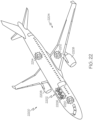
- aircraft 2200 produced by the service method 2100 may include airframe 2202 with a plurality of high-level systems 2204 and interior 2206.
- high-level systems 2204 include one or more of propulsion system 2208, electrical system 2210, hydraulic system 2212 and environmental system 2214. Any number of other systems may be included.
- propulsion system 2208 electrical system 2210
- hydraulic system 2212 hydraulic system 2212
- environmental system 2214 any number of other systems may be included.
- an aerospace example is shown, the principles disclosed herein may be applied to other industries, such as the automotive industry. Accordingly, in addition to aircraft 2200, the principles disclosed herein may apply to other vehicles, e.g., land vehicles, marine vehicles, space vehicles, etc.
- the disclosed systems and methods for associating test data for a part under test with an end item coordinate system may be employed during any one or more of the stages of the manufacturing and service method 2100.
- components or subassemblies corresponding to component and subassembly manufacturing (block 2106) may be fabricated or manufactured in a manner similar to components or subassemblies produced while aircraft 2200 is in service (block 2112).
- one or more examples of the system(s), method(s), or combination thereof may be utilized during production stages (block 2106 and block 2108), for example, by substantially expediting assembly of or reducing the cost of aircraft 2200.
- one or more examples of the system or method realizations, or a combination thereof may be utilized, for example and without limitation, while aircraft 2200 is in service (block 2112) and/or during maintenance and service (block 2114).
Landscapes
- Engineering & Computer Science (AREA)
- General Engineering & Computer Science (AREA)
- Mechanical Engineering (AREA)
- Connection Of Plates (AREA)
- Bolts, Nuts, And Washers (AREA)
Abstract
Description
- The present disclosure relates generally to nut retainer assemblies for blind fastener systems and, particularly, to nut retainer assemblies suitable for bonding to a substrate and used to retain a fastener nut for subsequent engagement by a fastener bolt. The retained fastener nut and the fastener bolt being used to join multiple substrates together. Various examples of the nut retainer assemblies and blind fastener systems are described. Various methods for assembling nut retainer assemblies on substrates are also described. Various configurations of the nut retainer assemblies provide a pre-installed fastener nut on a blind side of one substrate for one-sided installation of the fastener bolt from a working side of another substrate.
- Future airplane wing box architectures are getting smaller, which generates confined space and the need for a different fastening system that enables assembly from the outer mold line of the wing (e.g., skin/shear ties and skin/spar). The traditional nut plate styles are not applicable to the need for fuel tank and electromagnetic effect requirements. Current designs for nut retainers and one-sided fastener systems either are not able to take the required torque needed in high strength applications and or require the nut retainer to be mechanically attached to the substructure for them to work. Additionally, the current two-piece fastener systems far outperform any one-sided fastener system.
- Accordingly, those skilled in the art continue with research and development efforts to improve one-sided fastener systems for joining multiple substrates.
- Disclosed are examples of nut retainer assemblies for blind fastener systems, blind fastener systems and methods for assembling nut retainer assemblies on substrates. The following is a non-exhaustive list of examples, which may or may not be claimed, of the subject matter according to the present disclosure.
- In an example, a nut retainer assembly for a blind fastener system includes a bond washer and a nut retainer. The bond washer defines a longitudinal axis extending from a proximal washer end to a distal washer end. The bond washer includes a flange portion, a washer coupling portion, a first interior surface, a second interior surface and a bonding surface. The flange portion is at the proximal washer end. The washer coupling portion extends from the flange portion to the distal washer end. The first interior surface is associated with the flange portion and defines a first aperture. The second interior surface is associated with the washer coupling portion and includes internal threads. The bonding surface is associated with the flange portion at the proximal washer end. The nut retainer defines a proximal retainer end and a distal retainer end along the longitudinal axis and extending the longitudinal axis from the distal washer end to the distal retainer end. The nut retainer includes a retainer coupling portion, a nut retaining portion, a first exterior surface and a third interior surface. The retainer coupling portion at the proximal retainer end. The nut retaining portion extends from the retainer coupling portion to the distal retainer end. The first exterior surface is associated with the retainer coupling portion. The third interior surface is associated with the retainer coupling portion and the nut retaining portion. The third interior surface defines a central opening extending from the proximal retainer end to the distal retainer end.
- In an example, another nut retainer assembly for a blind fastener system includes a nut retainer. The nut retainer defines a longitudinal axis extending from a proximal retainer end to a distal retainer end. The nut retainer includes a flange portion, a nut retaining portion, a sixth interior surface and a bonding surface. The flange portion at the proximal retainer end. The nut retaining portion extends from the flange portion to the distal retainer end. The sixth interior surface is associated with the flange portion and the nut retaining portion. The sixth interior surface defines a central opening extending from the proximal retainer end to the distal retainer end. The bonding surface associated with the flange portion at the proximal retainer end.
- In an example, a blind fastener system includes a fastener bolt, a first substrate, a second substrate, a fastener nut and a nut retainer assembly. The fastener bolt includes a head portion, a shank portion and a threaded portion. The first substrate includes a first through hole sized to provide a first clearance fit for the fastener bolt and defines a first clamping surface to receive the fastener bolt. The first substrate also defines a first working surface. The second substrate includes a second through hole sized to provide a second clearance fit for the fastener bolt and defining a second clamping surface facing the first clamping surface. The second substrate also includes a second working surface to receive the fastener bolt. The fastener nut is for placement on the first working surface of the first substrate over the first through bore. The fastener nut includes a threaded bore. The nut retainer assembly defines a central opening sized and shaped to fit over and retain the fastener nut on the first working surface of the first substrate. The nut retainer assembly includes a bonding surface bordering the central opening. With the fastener nut disposed within the central opening, at least a portion of the bonding surface is bonded to the first working surface of the first substrate such that the second through hole of the second substrate, the first through hole of the first substrate and the threaded bore of the fastener nut provide for insertion of the fastener bolt and threaded engagement of the threaded portion of the fastener bolt with the threaded bore of the fastener nut.
- In an example, a method for assembling a nut retainer assembly on a substrate includes: (1) predrilling a hole through the substrate at a predetermined location for the nut retainer assembly; (2) applying an adhesive to at least a portion of a bonding surface on a bond washer of the nut retainer assembly; (3) bonding the bond washer over the hole in the substrate using the adhesive such that the hole is centered in relation to a first aperture through the bond washer; (4) positioning a fastener nut over the bond washer; (5) positioning a nut retainer with a central opening over the fastener nut and the bond washer, the nut retainer having external threads for engagement with internal threads of the bond washer, the central opening providing a clearance fit for the fastener nut; and (6) turning the nut retainer into threaded engagement with the bond washer to retain the fastener nut within the nut retainer assembly on the substrate.
- In an example, another method for assembling a nut retainer assembly on a substrate includes: (1) predrilling a hole through the substrate at a predetermined location for the nut retainer assembly; (2) applying an adhesive to at least a portion of a bonding surface on a nut retainer of the nut retainer assembly; (3) positioning a fastener nut in a central opening of the nut retainer, the central opening providing a clearance fit for the fastener nut; and (4) bonding the nut retainer over the hole in the substrate using the adhesive such that the hole is centered in relation to the central opening and the fastener nut is retained within the nut retainer assembly on the substrate.
- Other examples of the disclosed nut retainer assemblies for blind fastener systems, blind fastener systems and methods for assembling nut retainer assemblies on substrates will become apparent from the following detailed description, the accompanying drawings and the appended claims.
-
-
Fig. 1 is an exploded view of an example of a nut retainer assembly for a blind fastener system; -
Fig. 2 is a cross-sectional side view of an example of a blind fastener system; -
Fig. 3 is a cross-sectional side view of a portion of an example of a bond washer for the nut retainer assembly ofFig. 1 ; -
Fig. 4 is a cross-sectional side view of the nut retainer assembly ofFig. 1 positioned on a working surface of a substrate at a predetermined location for a hole through the substrate; -
Fig. 5 is a cross-sectional side view of the nut retainer assembly ofFig. 1 with a fastener nut retained therein; -
Fig. 6 is an exploded view of another example of a nut retainer assembly ofFig. 1 with a grip retainer extension and a grip extension washer; -
Fig. 7 is a cross-sectional side view of the nut retainer assembly ofFig. 1 with a nonconductive cap; -
Fig. 8 is an exploded view of yet another example of a nut retainer assembly that includes a seal washer; -
Fig. 9 is a cross-sectional side view of the nut retainer assembly ofFig. 8 with a nonconductive cap and a fastener nut retained therein; -
Fig. 10 is an exploded view of still another example of a nut retainer assembly that includes a retention washer; -
Fig. 11 is a cross-sectional side view of the nut retainer assembly ofFig. 10 with a nonconductive cap and a fastener nut retained therein; -
Fig. 12 is a cross-sectional side view of portions of examples of a bond washer, a retention washer and a nut retainer for the nut retainer assembly ofFig. 10 ; -
Fig. 13 is an exploded view of still yet another example of a nut retainer assembly that includes a seal washer and a retention washer; -
Fig. 14 is a cross-sectional side view of the nut retainer assembly ofFig. 13 with a nonconductive cap and a fastener nut retained therein; -
Fig. 15 is an exploded view of another example of a nut retainer assembly for a blind fastener system; -
Fig. 16 is a cross-sectional side view of the nut retainer assembly ofFig. 15 with a fastener nut retained therein; -
Fig. 17 is an exploded view of yet another example of a nut retainer assembly for a blind fastener system; -
Fig. 18 is a cross-sectional side view of the nut retainer assembly ofFig. 16 with a nonconductive cap and a fastener nut retained therein; -
Fig. 19 is a flow diagram of an example of a method for assembling a nut retainer assembly on a substrate; -
Fig. 20 is a flow diagram of another example of a method for assembling a nut retainer assembly on a substrate; -
Fig. 21 is a block diagram of aircraft production and service methodology that implements one or more of the examples of methods for assembling a nut retainer assembly on a substrate disclosed herein; and -
Fig. 22 is a schematic illustration of an aircraft that incorporates workpieces with multiple substrates that are joined using one or more of the examples of nut retainer assemblies, blind fastener systems and methods for assembling a nut retainer assembly on a substrate disclosed herein. - The various examples of nut retainer assemblies and blind fastener systems disclosed herein provide a high torque bonded nut retainer assembly for high strength one-sided fastener applications. Various configurations allow existing fasteners (e.g., fastener bolts and fastener nuts) to be installed in a one-sided application without damage and/or modifying the underlying substructure. The nut retainer assemblies can be used in locations where it is not desirable to add additional retaining features and/or damage the substrate material for the nut to be locked in place. The nut retainer assemblies utilize bond strength to counteract the torque of the fastener. The nut retainer assemblies and blind fastener systems can be used with off-the-shelf fastening standards with known characteristics and requirements. This eliminates or reduces the need to test the joint configuration.
- The various examples of nut retainer assemblies rely on a bonded surface to retain the nut until the fastener has sufficient clamp up force with the substructure. Once the sufficient clamp up force is achieved, the fastener nut takes the compressive load until a final torque is achieved. The bonded surface area is between a bonding surface on the nut retainer assembly and a working surface of a substate. The bond needs to be held just long enough such that the nut can clamp up on the surface. If there is not sufficient bonding area, the nut cannot clamp up. Torque values tested met or exceeded head side drive torque limits for brass, aluminum, titanium, A286, 300-series corrosion-resistant steel and Inconel/nickel alloy 718 fasteners with nuts. The nut retainer assemblies can be used in applications requiring a structural one-sided fastener and, particularly, in locations where there is insufficient access to install a two-part fastener system. The bonded nut retainers can be preinstalled on the substrate, then head side drive fasteners can be installed from an exterior working surface of another substrate.
- Referring generally to
Figs. 1-14 , by way of examples, the present disclosure is directed to anut retainer assembly 100 for ablind fastener system 200.Fig. 1 discloses an example of thenut retainer assembly 100.Fig. 2 discloses an example of theblind fastener system 200.Fig. 3 shows a cross-sectional side view of a portion of an example of abond washer 102 for thenut retainer assembly 100 ofFig. 1 .Fig. 4 shows a cross-sectional side view of thenut retainer assembly 100 ofFig. 1 positioned on a workingsurface 202 of asubstrate 204 at apredetermined location 402 for a hole 404 through thesubstrate 204.Fig. 5 shows a cross-sectional side view of thenut retainer assembly 100 ofFig. 1 with afastener nut 140 retained therein.Fig. 6 shows an exploded view of another example of thenut retainer assembly 100 ofFig. 1 with agrip retainer extension 602 and a grip extension washer 604.Fig. 7 shows a cross-sectional side view of thenut retainer assembly 100 ofFig. 1 with anonconductive cap 702 and afastener nut 140 retained therein. -
Fig. 8 show an exploded view of yet another example of anut retainer assembly 100 that includes aseal washer 802.Fig. 9 shows a cross-sectional side view of thenut retainer assembly 100 ofFig. 8 with anonconductive cap 702 and afastener nut 140 retained therein.Fig. 10 shows an exploded view of still another example of anut retainer assembly 100 that includes aretention washer 1002.Fig. 11 shows a cross-sectional side view of thenut retainer assembly 100 ofFig. 10 with anonconductive cap 702 and afastener nut 140 retained therein.Fig. 12 shows a cross-sectional side view of portions of examples of abond washer 102, aretention washer 1002 and anut retainer 124 for thenut retainer assembly 100 ofFig. 10 .Fig. 13 shows an exploded view of still yet another example of anut retainer assembly 100 that includes aseal washer 802 and aretention washer 1002.Fig. 14 shows a cross-sectional side view of thenut retainer assembly 100 ofFig. 13 with anonconductive cap 702 and afastener nut 140 retained therein. - With reference again to
Figs. 1-14 , in one or more examples, anut retainer assembly 100 for ablind fastener system 200 includes abond washer 102 and anut retainer 124. Thebond washer 102 defines alongitudinal axis 104 extending from aproximal washer end 106 to adistal washer end 108. Thebond washer 102 includes aflange portion 110, awasher coupling portion 112, a firstinterior surface 114, a secondinterior surface 118 and abonding surface 122. Theflange portion 110 is at theproximal washer end 106. Thewasher coupling portion 112 extends from theflange portion 110 to thedistal washer end 108. The firstinterior surface 114 is associated with theflange portion 110. The firstinterior surface 114 defines afirst aperture 116. The secondinterior surface 118 is associated with thewasher coupling portion 112. The secondinterior surface 118 includesinternal threads 120. Thebonding surface 122 is associated with theflange portion 110 at theproximal washer end 106. - The
nut retainer 124 defines aproximal retainer end 126 and adistal retainer end 128 along thelongitudinal axis 104 and extends thelongitudinal axis 104 from thedistal washer end 108 to thedistal retainer end 128. Thenut retainer 124 includes aretainer coupling portion 130, anut retaining portion 132, a firstexterior surface 134 and a thirdinterior surface 136. Theretainer coupling portion 130 is at theproximal retainer end 126. Thenut retaining portion 132 extends from theretainer coupling portion 130 to thedistal retainer end 128. The firstexterior surface 134 is associated with theretainer coupling portion 130. The thirdinterior surface 136 is associated with theretainer coupling portion 130 and thenut retaining portion 132. The thirdinterior surface 136 defines acentral opening 138 extending from theproximal retainer end 126 to thedistal retainer end 128. - In another example of the
nut retainer assembly 100, thebond washer 102 includes a metal material. In a further example, the metal material includes titanium, tungsten carbide, tungsten, high-strength corrosion-resistant steel, stainless steel or any other suitable metal material in any suitable combination. - In yet another example of the
nut retainer assembly 100, thenut retainer 124 includes a metal material. In a further example, the metal material includes titanium, tungsten carbide, tungsten, high-strength corrosion-resistant steel, stainless steel or any other suitable metal material in any suitable combination. - In still another example of the
nut retainer assembly 100, thebond washer 102 is configured to be bonded to a workingsurface 202 of asubstrate 204 using an adhesive 306. Thebond washer 102 being positioned over apredetermined location 402 for a hole 404 through which afastener bolt 206 is subsequently inserted from a clampingsurface 208 of thesubstrate 204 for engagement with afastener nut 140 retained by thenut retainer assembly 100. - In a further example, the adhesive 306 includes a BAC1010 adhesive, a type 111 adhesive, an EA 9394 adhesive, a BAC5010 adhesive, a
type 106 adhesive, a type 70 adhesive, a type 117 adhesive or any other suitable adhesive in any suitable combination. In another further example, the hole 404 includes pilot hole 406 predrilled at thepredetermined location 402 in conjunction with thebond washer 102 being bonded to the workingsurface 202 of thesubstrate 204. In yet another further example, the hole 404 includes a full-sized hole 408 predrilled at thepredetermined location 402 in conjunction with thebond washer 102 being bonded to the workingsurface 202 of thesubstrate 204. - In still yet another example of the
nut retainer assembly 100, the thirdinterior surface 136 associated with theretainer coupling portion 130 and thenut retaining portion 132 is sized and shaped to fit over afastener nut 140 between thenut retainer 124 and thebond washer 102. In this example, the firstexterior surface 134 associated with theretainer coupling portion 130 is threaded for engagement with theinternal threads 120 in thewasher coupling portion 112 to retain thefastener nut 140 between thenut retainer 124 and thebond washer 102. - In a further example, the
nut retainer 124 also includes a secondexterior surface 142 associated with thenut retaining portion 132 extending from theretainer coupling portion 130 to thedistal retainer end 128. In this example, the secondexterior surface 142 associated with thenut retaining portion 132 is sized and shaped to provide atorquing feature 144 proximate thedistal retainer end 128 for securing thenut retainer 124 within thenut retainer assembly 100 and for removing thenut retainer 124 from thenut retainer assembly 100. In an even further example, the torquingfeature 144 includes a 4-point torquing feature, a 6-point torquing feature, a 12-point torquing feature or any other suitable shape for thetorquing feature 148. - In another further example, the third
interior surface 136 associated with theretainer coupling portion 130 and thenut retaining portion 132 of thenut retainer 124 is sized and shaped to provide a firsthorizontal float 502 between acompressive feature 146 of thefastener nut 140 and thenut retainer 124 and a secondhorizontal float 503 between a torquingfeature 148 of thefastener nut 140 and thenut retainer 124. In an even further example, the firsthorizontal float 502 includes 20 thousandths of an inch, 18 thousandths to 22 thousandths of an inch, 15 thousandths to 25 thousandths of an inch or any other suitable dimension or range of dimensions for the firsthorizontal float 502. In another even further example, the secondhorizontal float 503 includes 9 thousandths of an inch, 7 thousandths to 11 thousandths of an inch, 5 thousandths to 13 thousandths of an inch or any other suitable dimension or range of dimensions for the secondhorizontal float 503. - In yet another further example, the third
interior surface 136 associated with theretainer coupling portion 130 is sized and shaped to provide avertical float 504 between acompressive feature 146 of thefastener nut 140 and thenut retainer 124. In an even further example, thevertical float 504 includes five thousandths of an inch, four thousandths to six thousandths of an inch, three thousandths to seven thousandths of an inch or any other suitable dimension or range of dimensions for thevertical float 504. - In still another further example, a portion of the
central opening 138 proximate thedistal retainer end 128 is sized and shaped to provide a clearance fit for atorquing feature 148 of thefastener nut 140 while preventing thefastener nut 140 from turning when it is retained between thenut retainer 124 and thebond washer 102. In an even further example, the portion of thecentral opening 138 proximate thedistal retainer end 128 is sized to fit the torquing feature 148 a 1/4 inch fastener nut, a 5/16 inch fastener nut, a 3/8 inch fastener nut, a 7/16 inch fastener nut, a 1/2 inch fastener nut, a 9/16 inch fastener nut, a 5/8 inch fastener nut, an 11/16 inch fastener nut, a 3/4 inch fastener nut, a 13/16 inch fastener nut, a 7/8 inch fastener nut, a 15/16 inch fastener nut, a one inch fastener nut or any other suitable dimension for thefastener nut 140. In another even further example, the portion of thecentral opening 138 proximate thedistal retainer end 128 is sized to fit thetorquing feature 148 of a 6 mm fastener nut, a 8 mm fastener nut, a 9 mm fastener nut, a 10 mm fastener nut, an 11 mm fastener nut, a 12 mm fastener nut, a 13 mm fastener nut, a 14 mm fastener nut, a 15 mm fastener nut, a 16 mm fastener nut, a 17 mm fastener nut, a 18 mm fastener nut, a 19 mm fastener nut, a 20 mm fastener nut or any other suitable dimension for thefastener nut 140. In yet another even further example, the portion of thecentral opening 138 proximate thedistal retainer end 128 is shaped to fit thetorquing feature 148 of a 4-point fastener nut, a 6-point fastener nut, a 12-point fastener nut or any other suitable shape for thetorquing feature 148. - In another example of the
nut retainer assembly 100, thenut retainer 124 also includes agrip retainer extension 602 between theproximal retainer end 126 and thedistal retainer end 128. In a further example, thegrip retainer extension 602 enables thenut retainer assembly 100 to be used for afastener bolt 206 with a longer grip length. - In yet another example, the
nut retainer assembly 100 also includes a grip extension washer 604 disposed within thecentral opening 138 at theproximal retainer end 126 between afastener nut 140 retained within thenut retainer 124 and thebond washer 102. In a further example, the grip extension washer 604 enables thenut retainer assembly 100 to be used for afastener bolt 206 with a longer grip length. - In still another example, the
nut retainer assembly 100 also includes anonconductive cap 702 to protect an operational environment within which thenut retainer assembly 100 is used from electromagnetic emissions and electrical sparks discharged bymetal components nut retainer assembly 100 andmetal fasteners exterior surface 704 associated with thewasher coupling portion 112 is configured to receive and engage with thenonconductive cap 702. - In still yet another example of the
nut retainer assembly 100, a fourthinterior surface 706 associated with thenonconductive cap 702 and the thirdexterior surface 704 of thewasher coupling portion 112 are threaded for engagement of thenonconductive cap 702 on thebond washer 102. - In a further example, a fourth
interior surface 706 associated with thenonconductive cap 702 and the thirdexterior surface 704 of thewasher coupling portion 112 are configured for twist-lock engagement. - In another further example, the
nonconductive cap 702 is transparent to permit internal inspection after thenut retainer assembly 100 is assembled with afastener nut 140 retained therein. - In yet another further example, the
nonconductive cap 702 includes a transparent polymer material. In an even further example, the transparent polymer material includes a transparent nylon material, a nylon TMDT material, a nylon 6-3-T material, a trimethylhexamethylenediamine material, a dimethyl terephthalate material or any other suitable transparent polymer material in any suitable combination. - In still another further example, the
nonconductive cap 702 includes aport 708 for receipt of a nonconductive sealant between a fourthinterior surface 706 associated with thenonconductive cap 702 and the thirdexterior surface 704 associated with thewasher coupling portion 112 after thenut retainer assembly 100 is assembled with afastener nut 140 retained therein to enhance protection of the operational environment from electromagnetic emissions and electrical sparks discharged bymetal components nut retainer assembly 100 andmetal fasteners - In another example of the
nut retainer assembly 100, theretainer coupling portion 130 includesexternal threads 150 for engagement with theinternal threads 120 in thewasher coupling portion 112 to retain afastener nut 140 between thenut retainer 124 and thebond washer 102. After theretainer coupling portion 130 and thewasher coupling portion 112 are fully engaged, theproximal retainer end 126 sits on theflange portion 110 of thebond washer 102 and at least a portion of acompressive feature 146 of thefastener nut 140 sits on theflange portion 110. - In a further example, the
bonding surface 122 of thebond washer 102 includes a recessedarea 302 along aperipheral portion 304 of thebonding surface 122 for receipt of an adhesive 306 and a contact area 308 extending from the recessedarea 302 to thefirst aperture 116 of theflange portion 110. In an even further example, the adhesive 306 includes a BAC1010 adhesive, a type 111 adhesive, an EA 9394 adhesive, a BAC5010 adhesive, atype 106 adhesive, a type 70 adhesive, a type 117 adhesive or any other suitable adhesive in any suitable combination. In another even further example, the recessedarea 302 is recessed in relation to the contact area 308 by five thousandths of an inch, four thousandths to six thousandths of an inch, three thousandths to seven thousandths of an inch or any other suitable dimension for the recess. In yet another even further example, thebond washer 102 is configured to be bonded to a workingsurface 202 of asubstrate 204 using the adhesive 306. Thebond washer 102 being positioned over apredetermined location 402 for a hole 404 through which afastener bolt 206 is subsequently inserted from a clampingsurface 208 of thesubstrate 204 for engagement with afastener nut 140 retained by thenut retainer assembly 100. - In another further example, the
first aperture 116 in theflange portion 110 of thebond washer 102 is sized to provide a clearance fit for afastener bolt 206 associated with thefastener nut 140. In this example, the thirdinterior surface 136 associated with theretainer coupling portion 130 defines asecond aperture 506 wider than thefirst aperture 116 and sized to provide a clearance fit for thefastener nut 140 at theproximal retainer end 126. - In yet another example of the
nut retainer assembly 100, the thirdinterior surface 136 associated with theretainer coupling portion 130 defines asecond aperture 506 wider than thefirst aperture 116 and sized to provide a clearance fit for thefastener nut 140 at theproximal retainer end 126. In this example, thenut retainer assembly 100 also includes aseal washer 802 disposed within thefirst aperture 116 and affixed to the firstinterior surface 114 associated with theflange portion 110 of thebond washer 102 after thenut retainer 124 and thebond washer 102 are assembled with afastener nut 140 retained therein. In a further example, thefirst aperture 116 is sized to provide an interference fit for theseal washer 802. Theseal washer 802 defines athird aperture 804 sized to provide an interference fit for afastener bolt 206 associated with thefastener nut 140. - In another further example, the
seal washer 802 includes a nonconductive polymer material. In an even further example, the nonconductive polymer material includes a polyether ether ketone material, a polyaryle ether ketone material, a polyether ketone material, a polyether ketone ether ketone ketone material, a polyetherimide material or any other suitable nonconductive polymer material. In yet another further example, theseal washer 802 enhances protection of an operational environment within which thenut retainer assembly 100 is used from electromagnetic emissions and electrical sparks discharged bymetal components nut retainer assembly 100 andmetal fasteners seal washer 802 acts as a fluid barrier in relation to theblind fastener system 200. In still yet another further example, theseal washer 802 extends from the firstinterior surface 114 associated with theflange portion 110 of thebond washer 102 to at least part of anon-threaded bore 806 in thecompressive feature 146 of thefastener nut 140. - In still another example of the
nut retainer assembly 100, thewasher coupling portion 112 defines afourth aperture 152 wider than thefirst aperture 116 in theflange portion 110 of thebond washer 102 thereby defining aninner portion 1102 of theflange portion 110 extending from thewasher coupling portion 112 to thefirst aperture 116 and an outer portion 1104 extending from thewasher coupling portion 112 to afourth exterior surface 1106 associated with theflange portion 110. - In a further example, the
nut retainer assembly 100 also includes aretention washer 1002 with a fifthinterior surface 1004, alip portion 1108 and anut support portion 1110. The fifthinterior surface 1004 defining afifth aperture 1112. Thelip portion 1108 having afirst thickness 1202. Thenut support portion 1110 having asecond thickness 1204 greater than thefirst thickness 1202. Theretention washer 1002 disposed within thefourth aperture 152 of thewasher coupling portion 112 with thelip portion 1108 overlaying theinner portion 1102 of theflange portion 110 for thebond washer 102 and thenut support portion 1110 extending into thefirst aperture 116 of theflange portion 110. - In another further example, the
retention washer 1002 includes a metal material. In an even further example, the metal material includes titanium, tungsten carbide, tungsten, high-strength corrosion-resistant steel, stainless steel or any other suitable metal material in any suitable combination. In yet another further example, thefirst aperture 116 in theflange portion 110 of thebond washer 102 is sized to provide a clearance fit for thenut support portion 1110 of theretention washer 1002. Thefourth aperture 152 of thewasher coupling portion 112 is sized to provide a clearance fit for thelip portion 1108 of theretention washer 1002. Thefifth aperture 1112 of theretention washer 1002 is sized to provide a clearance fit for afastener bolt 206 associated with afastener nut 140. In still another further example, the thirdinterior surface 136 associated with theretainer coupling portion 130 and thenut retaining portion 132 of thenut retainer 124 is sized and shaped to fit over afastener nut 140 between thenut retainer 124 and theretention washer 1002. - In still yet another further example, the
retainer coupling portion 130 includesexternal threads 150 for engagement with theinternal threads 120 in thewasher coupling portion 112 to retain afastener nut 140 between thenut retainer 124 and theretention washer 1002. After theretainer coupling portion 130 and thewasher coupling portion 112 are fully engaged, theproximal retainer end 126 sits on thelip portion 1108 of theretention washer 1002, at least a portion of acompressive feature 146 of thefastener nut 140 sits on thenut support portion 1110 of theretention washer 1002 and thenut support portion 1110 of theretention washer 1002 extends beyond thefirst aperture 116 in theflange portion 110 of thebond washer 102 to provide a contact surface 1206 configured to sit on a workingsurface 202 of asubstrate 204 prior to thebond washer 102. - In another further example, the
nut retainer 124 also includes agrip retainer extension 602 between theproximal retainer end 126 and thedistal retainer end 128. In yet another further example, thenut retainer assembly 100 also includes a grip extension washer 604 disposed within thecentral opening 138 at theproximal retainer end 126 between afastener nut 140 retained within thenut retainer 124 and theretention washer 1002. - In still another further example, the
nut retainer assembly 100 also includes aseal washer 802 disposed within thefifth aperture 1112 of theretention washer 1002 and affixed to the fifthinterior surface 1004 associated with theretention washer 1002 after thenut retainer 124, theretention washer 1002 and thebond washer 102 are assembled with afastener nut 140 retained therein. In an even further example, thefifth aperture 1112 of theretention washer 1002 is sized to provide an interference fit for theseal washer 802 and theseal washer 802 defines athird aperture 804 sized to provide an interference fit for afastener bolt 206 associated with thefastener nut 140. In another even further example, theseal washer 802 includes a nonconductive polymer material. In an even yet further example, the nonconductive polymer material includes a polyether ether ketone material, a polyaryle ether ketone material, a polyether ketone material, a polyether ketone ether ketone ketone material, a polyetherimide material or any other suitable nonconductive polymer material in any suitable combination. - In yet another even further example, the
seal washer 802 enhances protection of an operational environment within which thenut retainer assembly 100 is used from electromagnetic emissions and electrical sparks discharged bymetal components nut retainer assembly 100 andmetal fasteners seal washer 802 acts as a fluid barrier in relation to theblind fastener system 200. In still yet another even further example, theseal washer 802 extends from the fifthinterior surface 1004 associated with theretention washer 1002 to at least part of anon-threaded bore 806 in acompressive feature 146 of thefastener nut 140. - Referring generally to
Figs. 15-18 , by way of examples, the present disclosure is directed to anut retainer assembly 100 for ablind fastener system 200.Fig. 15 discloses an example of thenut retainer assembly 100.Fig. 16 shows a cross-sectional side view of thenut retainer assembly 100 ofFig. 15 with afastener nut 140 retained therein.Fig. 17 shows an exploded view of another example of thenut retainer assembly 100 ofFig. 1 with agrip retainer extension 602 and a grip extension washer 604.Fig. 18 shows a cross-sectional side view of thenut retainer assembly 100 ofFig. 15 with anonconductive cap 702 and afastener nut 140 retained therein. - With reference again to
Figs. 15-18 , in one or more examples, anut retainer assembly 100 for ablind fastener system 200 includes anut retainer 124 defining alongitudinal axis 104 extending from aproximal retainer end 126 to adistal retainer end 128. Thenut retainer 124 includes aflange portion 110, anut retaining portion 132, a sixthinterior surface 1502 and abonding surface 122. Theflange portion 110 at theproximal retainer end 126. Thenut retaining portion 132 extending from theflange portion 110 to thedistal retainer end 128. The sixthinterior surface 1502 is associated with theflange portion 110 and thenut retaining portion 132. The sixthinterior surface 1502 defines acentral opening 138 extending from theproximal retainer end 126 to thedistal retainer end 128. Thebonding surface 122 associated with theflange portion 110 at theproximal retainer end 126. - In another example of the
nut retainer assembly 100, thenut retainer 124 includes a metal material. In a further example, the metal material includes titanium, tungsten carbide, tungsten, high-strength corrosion-resistant steel, stainless steel or any other suitable metal material in any suitable combination. - In yet another example of the
nut retainer assembly 100, thenut retainer 124 is configured to be bonded to a workingsurface 202 of asubstrate 204 using an adhesive 306. Thenut retainer 124 being positioned over afastener nut 140 at apredetermined location 402 for a hole 404 through which afastener bolt 206 is subsequently inserted from a clampingsurface 208 of thesubstrate 204 for engagement with thefastener nut 140 retained between thenut retainer 124 and the workingsurface 202. In a further example, the adhesive 306 includes a BAC1010 adhesive, a type 111 adhesive, an EA 9394 adhesive, a BAC5010 adhesive, atype 106 adhesive, a type 70 adhesive, a type 117 adhesive or any other suitable adhesive in any suitable combination. In another further example, the hole 404 includes a pilot hole 406 predrilled at thepredetermined location 402 in conjunction with thenut retainer 124 being bonded to the workingsurface 202 of thesubstrate 204. In yet another further example, the hole 404 includes a full-sized hole 408 predrilled at thepredetermined location 402 in conjunction with thenut retainer 124 being bonded to the workingsurface 202 of thesubstrate 204. - In still another example of the
nut retainer assembly 100, the sixthinterior surface 1502 associated with theflange portion 110 and thenut retaining portion 132 is sized and shaped to fit over afastener nut 140 between thenut retainer 124 and a workingsurface 202 of asubstrate 204. - In a further example, the sixth
interior surface 1502 associated with theflange portion 110 and thenut retaining portion 132 is sized and shaped to provide a firsthorizontal float 502 between acompressive feature 146 of thefastener nut 140 and thenut retainer 124 and a secondhorizontal float 503 between a torquingfeature 148 of thefastener nut 140 and thenut retainer 124. In an even further example, the firsthorizontal float 502 includes 20 thousandths of an inch, 18 thousandths to 22 thousandths of an inch, 15 thousandths to 25 thousandths of an inch or any other suitable dimension for the firsthorizontal float 502. In another even further example, the secondhorizontal float 503 includes 9 thousandths of an inch, 7 thousandths to 11 thousandths of an inch, 5 thousandths to 13 thousandths of an inch or any other suitable dimension for the secondhorizontal float 503. - In another further example, the sixth
interior surface 1502 associated with theflange portion 110 and an adjacent part of thenut retaining portion 132 is sized and shaped to provide avertical float 504 between acompressive feature 146 of thefastener nut 140 and thenut retainer 124. In an even further example, thevertical float 504 includes five thousandths of an inch, four thousandths to six thousandths of an inch, three thousandths to seven thousandths of an inch or any other suitable dimension for thevertical float 504. - In yet another further example, a portion of the
central opening 138 proximate thedistal retainer end 128 is sized and shaped to provide a clearance fit for atorquing feature 148 of thefastener nut 140 while preventing thefastener nut 140 from turning when it is retained between thenut retainer 124 and the workingsurface 202 of thesubstrate 204. In an even further example, the portion of thecentral opening 138 proximate thedistal retainer end 128 is sized to fit thetorquing feature 148 of a 1/4 inch fastener nut, a 5/16 inch fastener nut, a 3/8 inch fastener nut, a 7/16 inch fastener nut, a 1/2 inch fastener nut, a 9/16 inch fastener nut, a 5/8 inch fastener nut, an 11/16 inch fastener nut, a 3/4 inch fastener nut, a 13/16 inch fastener nut, a 7/8 inch fastener nut, a 15/16 inch fastener nut, a one inch fastener nut or any other suitable dimension for thefastener nut 140. In another even further example, the portion of thecentral opening 138 proximate thedistal retainer end 128 is sized to fit thetorquing feature 148 of a 6 mm fastener nut, a 8 mm fastener nut, a 9 mm fastener nut, a 10 mm fastener nut, an 11 mm fastener nut, a 12 mm fastener nut, a 13 mm fastener nut, a 14 mm fastener nut, a 15 mm fastener nut, a 16 mm fastener nut, a 17 mm fastener nut, a 18 mm fastener nut, a 19 mm fastener nut, a 20 mm fastener nut or any other suitable dimension for thefastener nut 140. In yet another even further example, the portion of thecentral opening 138 proximate thedistal retainer end 128 is shaped to fit thetorquing feature 148 of a 4-point fastener nut, a 6-point fastener nut, a 12-point fastener nut or any other suitable shape for thetorquing feature 148. - In still yet another example of the
nut retainer assembly 100, thenut retainer 124 also includes agrip retainer extension 602 between theproximal retainer end 126 and thedistal retainer end 128. In a further example, thegrip retainer extension 602 enables thenut retainer assembly 100 to be used for afastener bolt 206 with a longer grip length. In another example of thenut retainer assembly 100, thenut retainer assembly 100 also includes a grip extension washer 604 disposed within thecentral opening 138 at theproximal retainer end 126 between afastener nut 140 retained within thenut retainer 124 and asubstrate 204. In a further example, the grip extension washer 604 enables thenut retainer assembly 100 to be used for afastener bolt 206 with a longer grip length. - In yet another example of the
nut retainer assembly 100, thenut retainer assembly 100 also includes anonconductive cap 702 to protect an operational environment within which thenut retainer assembly 100 is used from electromagnetic emissions and electrical sparks discharged bymetal components 124 of thenut retainer assembly 100 andmetal fasteners exterior surface 134 associated with thenut retainer 124 is configured to receive and engage with thenonconductive cap 702. In a further example, a fourthinterior surface 706 associated with thenonconductive cap 702 and the firstexterior surface 134 of thenut retainer 124 are threaded for engagement of thenonconductive cap 702 on thenut retainer 124. In another further example, a fourthinterior surface 706 associated with thenonconductive cap 702 and the firstexterior surface 134 of thenut retainer 124 are configured for twist-lock engagement. - In yet another further example, the
nonconductive cap 702 is transparent to permit internal inspection after thenut retainer assembly 100 is assembled with afastener nut 140 retained therein. In still another further example, thenonconductive cap 702 includes a transparent polymer material. In an even further example, the transparent polymer material includes a transparent nylon material, a nylon TMDT material, a nylon 6-3-T material, a trimethylhexamethylenediamine material, a dimethyl terephthalate material or any other suitable transparent polymer material in any suitable combination. - In still yet another further example, the
nonconductive cap 702 includes aport 708 for receipt of a nonconductive sealant between a fourthinterior surface 706 associated with thenonconductive cap 702 and the firstexterior surface 134 of thenut retainer 124 after thenut retainer assembly 100 is assembled with afastener nut 140 retained therein to enhance protection of the operational environment from electromagnetic emissions and electrical sparks discharged bymetal components 124 of thenut retainer assembly 100 andmetal fasteners - Referring generally to
Figs. 1-18 , by way of examples, the present disclosure is directed to ablind fastener system 200.Fig. 1 discloses an example of anut retainer assembly 100.Fig. 2 discloses an example of theblind fastener system 200.Fig. 3 shows a cross-sectional side view of a portion of an example of abond washer 102 for thenut retainer assembly 100 ofFig. 1 .Fig. 4 shows a cross-sectional side view of thenut retainer assembly 100 ofFig. 1 positioned on a workingsurface 202 of asubstrate 204 at apredetermined location 402 for a hole 404 through thesubstrate 204.Fig. 5 shows a cross-sectional side view of thenut retainer assembly 100 ofFig. 1 with afastener nut 140 retained therein.Fig. 6 shows an exploded view of another example of thenut retainer assembly 100 ofFig. 1 with agrip retainer extension 602 and a grip extension washer 604.Fig. 7 shows a cross-sectional side view of thenut retainer assembly 100 ofFig. 1 with anonconductive cap 702 and afastener nut 140 retained therein.Fig. 8 show an exploded view of yet another example of anut retainer assembly 100 that includes aseal washer 802. -
Fig. 9 shows a cross-sectional side view of thenut retainer assembly 100 ofFig. 8 with anonconductive cap 702 and afastener nut 140 retained therein.Fig. 10 shows an exploded view of still another example of anut retainer assembly 100 that includes aretention washer 1002.Fig. 11 shows a cross-sectional side view of thenut retainer assembly 100 ofFig. 10 with anonconductive cap 702 and afastener nut 140 retained therein.Fig. 12 shows a cross-sectional side view of portions of examples of abond washer 102, aretention washer 1002 and anut retainer 124 for thenut retainer assembly 100 ofFig. 10 .Fig. 13 shows an exploded view of still yet another example of anut retainer assembly 100 that includes aseal washer 802 and aretention washer 1002.Fig. 14 shows a cross-sectional side view of thenut retainer assembly 100 ofFig. 13 with anonconductive cap 702 and afastener nut 140 retained therein.Fig. 15 discloses another example of anut retainer assembly 100.Fig. 16 shows a cross-sectional side view of thenut retainer assembly 100 ofFig. 15 with afastener nut 140 retained therein.Fig. 17 shows an exploded view of another example of thenut retainer assembly 100 ofFig. 1 with agrip retainer extension 602 and a grip extension washer 604.Fig. 18 shows a cross-sectional side view of thenut retainer assembly 100 ofFig. 15 with anonconductive cap 702 and afastener nut 140 retained therein. - With reference again to
Figs. 1-18 , in one or more examples, ablind fastener system 200 includes afastener bolt 206, afirst substrate 204, asecond substrate 210, afastener nut 140 and anut retainer assembly 100. Thefastener bolt 206 includes a head portion, a shank portion and a threaded portion. Thefirst substrate 204 includes a first through hole sized to provide a first clearance fit for thefastener bolt 206 and defines afirst clamping surface 208 to receive thefastener bolt 206. Thesubstrate 204 further defines a first workingsurface 202. Thesecond substrate 210 includes a second through hole sized to provide a second clearance fit for thefastener bolt 206 and defines asecond clamping surface 212 facing thefirst clamping surface 208. The second substrate further defines a second workingsurface 214 to receive thefastener bolt 206. Thefastener nut 140 for placement on the first workingsurface 202 of thefirst substrate 204 over the first through bore. Thefastener nut 140 includes a threadedbore 216. Thenut retainer assembly 100 defines acentral opening 138 sized and shaped to fit over and retain thefastener nut 140 on the first workingsurface 202 of thefirst substrate 204. Thenut retainer assembly 100 includes abonding surface 122 bordering thecentral opening 138. With thefastener nut 140 disposed within thecentral opening 138, at least a portion of thebonding surface 122 is bonded to the first workingsurface 202 of thefirst substrate 204 such that the second through hole of thesecond substrate 210, the first through hole of thefirst substrate 204 and the threaded bore 216 of thefastener nut 140 provide for insertion of thefastener bolt 206 and threaded engagement of the threaded portion of thefastener bolt 206 with the threaded bore 216 of thefastener nut 140. - In another example of the
blind fastener system 200,nut retainer assembly 100 also includes abond washer 102 and anut retainer 124. Thebond washer 102 defines alongitudinal axis 104 extending from aproximal washer end 106 to adistal washer end 108. Thebond washer 102 includes aflange portion 110, awasher coupling portion 112, a firstinterior surface 114, a secondinterior surface 118 and thebonding surface 122. Theflange portion 110 at theproximal washer end 106. Thewasher coupling portion 112 extending from theflange portion 110 to thedistal washer end 108. The firstinterior surface 114 is associated with theflange portion 110. The firstinterior surface 114 defining afirst aperture 116. The secondinterior surface 118 is associated with thewasher coupling portion 112. The secondinterior surface 118 includesinternal threads 120. Thebonding surface 122 associated with theflange portion 110 at theproximal washer end 106. Thenut retainer 124 defines aproximal retainer end 126 and adistal retainer end 128 along thelongitudinal axis 104 and extending thelongitudinal axis 104 from thedistal washer end 108 to thedistal retainer end 128. Thenut retainer 124 includes aretainer coupling portion 130, anut retaining portion 132, a firstexterior surface 134 and a thirdinterior surface 136. Theretainer coupling portion 130 at theproximal retainer end 126. Thenut retaining portion 132 extending from theretainer coupling portion 130 to thedistal retainer end 128. The firstexterior surface 134 associated with theretainer coupling portion 130. The thirdinterior surface 136 is associated with theretainer coupling portion 130 and thenut retaining portion 132. The thirdinterior surface 136 defines thecentral opening 138. Thecentral opening 138 extending from theproximal retainer end 126 to thedistal retainer end 128. - In a further example, the
nut retainer 124 also includes agrip retainer extension 602 between theproximal retainer end 126 and thedistal retainer end 128. In another further example, thenut retainer assembly 100 also includes a grip extension washer 604 disposed within thecentral opening 138 at theproximal retainer end 126 between thefastener nut 140 retained within thenut retainer 124 and thebond washer 102. - In yet another further example, the
nut retainer assembly 100 also includes anonconductive cap 702 to protect an operational environment within which thenut retainer assembly 100 is used from electromagnetic emissions and electrical sparks discharged bymetal components nut retainer assembly 100 andmetal fasteners exterior surface 704 associated with thewasher coupling portion 112 is configured to receive and engage with thenonconductive cap 702. - In still another further example, the
retainer coupling portion 130 includesexternal threads 150 for engagement with theinternal threads 120 in thewasher coupling portion 112 to retain thefastener nut 140 between thenut retainer 124 and thebond washer 102. After theretainer coupling portion 130 and thewasher coupling portion 112 are fully engaged, theproximal retainer end 126 sits on theflange portion 110 of thebond washer 102 and at least a portion of acompressive feature 146 of thefastener nut 140 sits on theflange portion 110. In an even further example, thebonding surface 122 of thebond washer 102 includes a recessedarea 302 along aperipheral portion 304 of thebonding surface 122 for receipt of an adhesive 306 and a contact area 308 extending from the recessedarea 302 to thefirst aperture 116 of theflange portion 110. - In still yet another further example, the third
interior surface 136 associated with theretainer coupling portion 130 defines asecond aperture 506 wider than thefirst aperture 116 and sized to provide a clearance fit for thefastener nut 140 at theproximal retainer end 126. In this example, thenut retainer assembly 100 also includes aseal washer 802 disposed within thefirst aperture 116 and affixed to the firstinterior surface 114 associated with theflange portion 110 of thebond washer 102 after thenut retainer 124 and thebond washer 102 are assembled with thefastener nut 140 retained therein. - In another further example, the
washer coupling portion 112 defines afourth aperture 152 wider than thefirst aperture 116 in theflange portion 110 of thebond washer 102 thereby defining aninner portion 1102 of theflange portion 110 extending from thewasher coupling portion 112 to thefirst aperture 116 and an outer portion 1104 extending from thewasher coupling portion 112 to afourth exterior surface 1106 associated with theflange portion 110. In an even further example, thenut retainer assembly 100 also includes aretention washer 1002 with a fifthinterior surface 1004, alip portion 1108 and anut support portion 1110. The fifthinterior surface 1004 defining afifth aperture 1112. Thelip portion 1108 having afirst thickness 1202. Thenut support portion 1110 having asecond thickness 1204 greater than thefirst thickness 1202. Theretention washer 1002 disposed within thefourth aperture 152 of thewasher coupling portion 112 with thelip portion 1108 overlaying theinner portion 1102 of theflange portion 110 for thebond washer 102 and thenut support portion 1110 extending into thefirst aperture 116 of theflange portion 110. - In an even yet further example, the
nut retainer assembly 100 also includes aseal washer 802 disposed within thefifth aperture 1112 of theretention washer 1002 and affixed to the fifthinterior surface 1004 associated with theretention washer 1002 after thenut retainer 124, theretention washer 1002 and thebond washer 102 are assembled with thefastener nut 140 retained therein. - In yet another example of the
blind fastener system 200, thenut retainer assembly 100 includes anut retainer 124 defining alongitudinal axis 104 extending from aproximal retainer end 126 to adistal retainer end 128. Thenut retainer 124 includes aflange portion 110, anut retaining portion 132, a sixthinterior surface 1502 and thebonding surface 122. Theflange portion 110 at theproximal retainer end 126. Thenut retaining portion 132 extending from theflange portion 110 to thedistal retainer end 128. The sixthinterior surface 1502 is associated with theflange portion 110 and thenut retaining portion 132. The sixthinterior surface 1502 defining thecentral opening 138 extending from theproximal retainer end 126 to thedistal retainer end 128. Thebonding surface 122 associated with theflange portion 110 at theproximal retainer end 126. In a further example, thenut retainer 124 also includes agrip retainer extension 602 between theproximal retainer end 126 and thedistal retainer end 128. In another further example, thenut retainer assembly 100 also includes a grip extension washer 604 disposed within thecentral opening 138 at theproximal retainer end 126 between thefastener nut 140 retained within thenut retainer 124 and asubstrate 204. In yet another further example, the nut retainer assembly (100) also includes anonconductive cap 702 to protect an operational environment within which thenut retainer assembly 100 is used from electromagnetic emissions and electrical sparks discharged bymetal components 124 of thenut retainer assembly 100 andmetal fasteners exterior surface 134 associated with thenut retainer 124 is configured to receive and engage with thenonconductive cap 702. - Referring generally to
Figs. 1-14 and19 , by way of examples, the present disclosure is directed to amethod 1900 for assembling anut retainer assembly 100 on asubstrate 204.Fig. 19 discloses themethod 1900.Fig. 1 discloses an example of thenut retainer assembly 100.Fig. 2 discloses an example of ablind fastener system 200.Fig. 3 shows a cross-sectional side view of a portion of an example of abond washer 102 for thenut retainer assembly 100 ofFig. 1 .Fig. 4 shows a cross-sectional side view of thenut retainer assembly 100 ofFig. 1 positioned on a workingsurface 202 of asubstrate 204 at apredetermined location 402 for a hole 404 through thesubstrate 204.Fig. 5 shows a cross-sectional side view of thenut retainer assembly 100 ofFig. 1 with afastener nut 140 retained therein.Fig. 6 shows an exploded view of another example of thenut retainer assembly 100 ofFig. 1 with agrip retainer extension 602 and a grip extension washer 604.Fig. 7 shows a cross-sectional side view of thenut retainer assembly 100 ofFig. 1 with anonconductive cap 702 and afastener nut 140 retained therein. -
Fig. 8 show an exploded view of yet another example of anut retainer assembly 100 that includes aseal washer 802.Fig. 9 shows a cross-sectional side view of thenut retainer assembly 100 ofFig. 8 with anonconductive cap 702 and afastener nut 140 retained therein.Fig. 10 shows an exploded view of still another example of anut retainer assembly 100 that includes aretention washer 1002.Fig. 11 shows a cross-sectional side view of thenut retainer assembly 100 ofFig. 10 with anonconductive cap 702 and afastener nut 140 retained therein.Fig. 12 shows a cross-sectional side view of portions of examples of abond washer 102, aretention washer 1002 and anut retainer 124 for thenut retainer assembly 100 ofFig. 10 .Fig. 13 shows an exploded view of still yet another example of anut retainer assembly 100 that includes aseal washer 802 and aretention washer 1002.Fig. 14 shows a cross-sectional side view of thenut retainer assembly 100 ofFig. 13 with anonconductive cap 702 and afastener nut 140 retained therein. - With reference again to
Figs. 1-14 and19 , in one or more examples, a method 1900 (seeFig. 19 ) for assembling anut retainer assembly 100 on asubstrate 204 includes predrilling 1902 a hole 404 through thesubstrate 204 at apredetermined location 402 for thenut retainer assembly 100. At 1904, an adhesive 306 is applied to at least a portion of abonding surface 122 on abond washer 102 of thenut retainer assembly 100. At 1908, thebond washer 102 is bonded over the hole 404 in thesubstrate 204 using the adhesive 306 such that the hole 404 is centered in relation to afirst aperture 116 through thebond washer 102. At 1908, afastener nut 140 is positioned over thebond washer 102. At 1910, anut retainer 124 with acentral opening 138 is positioned over thefastener nut 140 and thebond washer 102. Thenut retainer 124 havingexternal threads 150 for engagement withinternal threads 120 of thebond washer 102. Thecentral opening 138 provides a clearance fit for thefastener nut 140. At 1912, thenut retainer 124 is turned into threaded engagement with thebond washer 102 to retain thefastener nut 140 within thenut retainer assembly 100 on thesubstrate 204. - In another example of the
method 1900, the hole 404 through thesubstrate 204 includes a pilot hole 406 for subsequent drilling of a full-sized hole 408 that provides a clearance fit to afastener bolt 206 associated with thefastener nut 140 retained by thenut retainer assembly 100. In yet another example of themethod 1900, the hole 404 through thesubstrate 204 includes a full-sized hole 408 that provides a clearance fit to afastener bolt 206 associated with thefastener nut 140 retained by thenut retainer assembly 100. In still another example of themethod 1900, thecentral opening 138 of thenut retainer 124 is sized and shaped to provide a firsthorizontal float 502 between acompressive feature 146 of thefastener nut 140 and thenut retainer 124 and a secondhorizontal float 503 between a torquingfeature 148 of thefastener nut 140 and thenut retainer 124. In still yet another example of themethod 1900, thecentral opening 138 of thenut retainer 124 is sized and shaped to provide avertical float 504 between acompressive feature 146 of thefastener nut 140 and thenut retainer 124. In another example of themethod 1900, a portion of thecentral opening 138 proximate adistal retainer end 128 is sized and shaped to provide a clearance fit for atorquing feature 148 of thefastener nut 140 while preventing thefastener nut 140 from turning when it is retained between thenut retainer 124 and thebond washer 102. - Referring generally to
Figs. 15-18 and20 , by way of examples, the present disclosure is directed to amethod 2000 for assembling anut retainer assembly 100 on asubstrate 204.Fig. 20 discloses themethod 2000.Fig. 15 discloses an example of thenut retainer assembly 100.Fig. 16 shows a cross-sectional side view of thenut retainer assembly 100 ofFig. 15 with afastener nut 140 retained therein.Fig. 17 shows an exploded view of another example of thenut retainer assembly 100 ofFig. 1 with agrip retainer extension 602 and a grip extension washer 604.Fig. 18 shows a cross-sectional side view of thenut retainer assembly 100 ofFig. 15 with anonconductive cap 702 and afastener nut 140 retained therein. - With reference again to
Figs. 15-18 and20 , in one or more examples, a method 2000 (seeFig. 20 ) for assembling anut retainer assembly 100 on asubstrate 204 includes predrilling 2002 a hole 404 through thesubstrate 204 at apredetermined location 402 for thenut retainer assembly 100. At 2004, an adhesive 306 is applied to at least a portion of abonding surface 122 on anut retainer 124 of thenut retainer assembly 100. At 2006, afastener nut 140 is positioned in acentral opening 138 of thenut retainer 124. Thecentral opening 138 provides a clearance fit for thefastener nut 140. At 2008, thenut retainer 124 is bonded over the hole 404 in thesubstrate 204 using the adhesive 306 such that the hole 404 is centered in relation to thecentral opening 138 and thefastener nut 140 is retained within thenut retainer assembly 100 on thesubstrate 204. - In another example of the
method 2000, the hole 404 through thesubstrate 204 includes a pilot hole 406 for subsequent drilling of a full-sized hole 408 that provides a clearance fit to afastener bolt 206 associated with thefastener nut 140 retained by thenut retainer assembly 100. - In yet another example of the
method 2000, the hole 404 through thesubstrate 204 includes a full-sized hole 408 that provides a clearance fit to afastener bolt 206 associated with thefastener nut 140 retained by thenut retainer assembly 100. - In still another example of the
method 2000, thecentral opening 138 of thenut retainer 124 is sized and shaped to provide a firsthorizontal float 502 between acompressive feature 146 of thefastener nut 140 and thenut retainer 124 and a secondhorizontal float 503 between a torquingfeature 148 of thefastener nut 140 and thenut retainer 124. - In still yet another example of the
method 2000, thecentral opening 138 of thenut retainer 124 is sized and shaped to provide avertical float 504 between acompressive feature 146 of thefastener nut 140 and thenut retainer 124. - In another example of the
method 2000, a portion of thecentral opening 138 proximate adistal retainer end 128 is sized and shaped to provide a clearance fit for atorquing feature 148 of thefastener nut 140 while preventing thefastener nut 140 from turning when it is retained between thenut retainer 124 and thesubstrate 204. - Examples of
nut retainer assemblies 100,blind fastener systems 200 andmethods nut retainer assembly 100 on asubstrate 204 may be related to or used in the context of aircraft manufacturing. Although an aircraft example is described, the examples and principles disclosed herein may be applied to other products in the aerospace industry and other industries, such as the automotive industry, the space industry, the construction industry and other design and manufacturing industries. Accordingly, in addition to aircraft, the examples and principles disclosed herein may apply to the use of various products in the manufacture of various types of vehicles and in the construction of various types of buildings. - The preceding detailed description refers to the accompanying drawings, which illustrate specific examples described by the present disclosure. Other examples having different structures and operations do not depart from the scope of the present disclosure. Like reference numerals may refer to the same feature, element, or component in the different drawings. Throughout the present disclosure, any one of a plurality of items may be referred to individually as the item and a plurality of items may be referred to collectively as the items and may be referred to with like reference numerals. Moreover, as used herein, a feature, element, component, or step preceded with the word "a" or "an" should be understood as not excluding a plurality of features, elements, components, or steps, unless such exclusion is explicitly recited.
- Illustrative, non-exhaustive examples, which may be, but are not necessarily, claimed, of the subject matter according to the present disclosure are provided above. Reference herein to "example" means that one or more feature, structure, element, component, characteristic and/or operational step described in connection with the example is included in at least one aspect, embodiment and/or implementation of the subject matter according to the present disclosure. Thus, the phrases "an example," "another example," "one or more examples," and similar language throughout the present disclosure may, but do not necessarily, refer to the same example. Further, the subject matter characterizing any one example may, but does not necessarily, include the subject matter characterizing any other example. Moreover, the subject matter characterizing any one example may be, but is not necessarily, combined with the subject matter characterizing any other example.
- As used herein, a system, apparatus, device, structure, article, element, component, or hardware "configured to" perform a specified function is indeed capable of performing the specified function without any alteration, rather than merely having potential to perform the specified function after further modification. In other words, the system, apparatus, device, structure, article, element, component, or hardware "configured to" perform a specified function is specifically selected, created, implemented, utilized, programmed and/or designed for the purpose of performing the specified function. As used herein, "configured to" denotes existing characteristics of a system, apparatus, structure, article, element, component, or hardware that enable the system, apparatus, structure, article, element, component, or hardware to perform the specified function without further modification. For purposes of this disclosure, a system, apparatus, device, structure, article, element, component, or hardware described as being "configured to" perform a particular function may additionally or alternatively be described as being "adapted to" and/or as being "operative to" perform that function.
- Unless otherwise indicated, the terms "first," "second," "third," etc., are used herein merely as labels and are not intended to impose ordinal, positional, or hierarchical requirements on the items to which these terms refer. Moreover, reference to, e.g., a "second" item does not require or preclude the existence of, e.g., a "first" or lower-numbered item and/or, e.g., a "third" or higher-numbered item.
- As used herein, the phrase "at least one of," when used with a list of items, means different combinations of one or more of the listed items may be used and only one of each item in the list may be needed. For example, "at least one of item A, item B and item C" may include, without limitation, item A or item A and item B. This example also may include item A, item B and item C or item B and item C. In other examples, "at least one of' may be, for example, without limitation, two of item A, one of item B and ten of item C; four of item B and seven of item C; and other suitable combinations. As used herein, the term "and/or" and the "/" symbol includes any and all combinations of one or more of the associated listed items.
- As used herein, the terms "coupled," "coupling," and similar terms refer to two or more elements that are joined, linked, fastened, attached, connected, put in communication, or otherwise associated (e.g., mechanically, electrically, fluidly, optically, electromagnetically) with one another. In various examples, the elements may be associated directly or indirectly. As an example, element A may be directly associated with element B. As another example, element A may be indirectly associated with element B, for example, via another element C. It will be understood that not all associations among the various disclosed elements are necessarily represented. Accordingly, couplings other than those depicted in the figures may also exist.
- As used herein, the term "approximately" refers to or represents a condition that is close to, but not exactly, the stated condition that still performs the desired function or achieves the desired result. As an example, the term "approximately" refers to a condition that is within an acceptable predetermined tolerance or accuracy, such as to a condition that is within 10% of the stated condition. However, the term "approximately" does not exclude a condition that is exactly the stated condition. As used herein, the term "substantially" refers to a condition that is essentially the stated condition that performs the desired function or achieves the desired result.
- In
Figs. 1-18 , referred to above, may represent functional elements, features, or components thereof and do not necessarily imply any particular structure. Accordingly, modifications, additions and/or omissions may be made to the illustrated structure. Additionally, those skilled in the art will appreciate that not all elements, features and/or components described and illustrated inFigs. 1-18 , referred to above, need be included in every example and not all elements, features and/or components described herein are necessarily depicted in each illustrative example. Accordingly, some of the elements, features and/or components described and illustrated inFigs. 1-18 may be combined in various ways without the need to include other features described and illustrated inFigs. 1-18 , other drawing figures and/or the accompanying disclosure, even though such combination or combinations are not explicitly illustrated herein. Similarly, additional features not limited to the examples presented, may be combined with some or all the features shown and described herein. Unless otherwise explicitly stated, the schematic illustrations of the examples depicted inFigs. 1-18 , referred to above, are not meant to imply structural limitations with respect to the illustrative example. Rather, although one illustrative structure is indicated, it is to be understood that the structure may be modified when appropriate. Accordingly, modifications, additions and/or omissions may be made to the illustrated structure. Furthermore, elements, features and/or components that serve a similar, or at least substantially similar, purpose are labeled with like numbers in each ofFigs. 1-18 and such elements, features and/or components may not be discussed in detail herein with reference to each ofFigs. 1-18 . Similarly, all elements, features and/or components may not be labeled in each ofFigs. 1-18 , but reference numerals associated therewith may be utilized herein for consistency. - In
Figs. 19 and20 , referred to above, the blocks may represent operations, steps and/or portions thereof and lines connecting the various blocks do not imply any particular order or dependency of the operations or portions thereof. It will be understood that not all dependencies among the various disclosed operations are necessarily represented.Figs. 19 and20 and the accompanying disclosure describing the operations of the disclosed methods set forth herein should not be interpreted as necessarily determining a sequence in which the operations are to be performed. Rather, although one illustrative order is indicated, it is to be understood that the sequence of the operations may be modified when appropriate. Accordingly, modifications, additions and/or omissions may be made to the operations illustrated and certain operations may be performed in a different order or simultaneously. Additionally, those skilled in the art will appreciate that not all operations described need be performed. - Further, references throughout the present specification to features, advantages, or similar language used herein do not imply that all the features and advantages that may be realized with the examples disclosed herein should be, or are in, any single example. Rather, language referring to the features and advantages is understood to mean that a specific feature, advantage, or characteristic described in connection with an example is included in at least one example. Thus, discussion of features, advantages and similar language used throughout the present disclosure may, but does not necessarily, refer to the same example.
- Examples of the subject matter disclosed herein may be described in the context of aircraft manufacturing and
service method 2100 as shown inFig. 21 andaircraft 2200 as shown inFig. 22 . In one or more examples, the disclosed methods and systems for associating test data for a part under test with an end item coordinate system may be used in aircraft manufacturing. During pre-production, theservice method 2100 may include specification and design (block 2102) ofaircraft 2200 and material procurement (block 2104). During production, component and subassembly manufacturing (block 2106) and system integration (block 2108) ofaircraft 2200 may take place. Thereafter,aircraft 2200 may go through certification and delivery (block 2110) to be placed in service (block 2112). While in service,aircraft 2200 may be scheduled for routine maintenance and service (block 2114). Routine maintenance and service may include modification, reconfiguration, refurbishment, etc. of one or more systems ofaircraft 2200. - Each of the processes of the
service method 2100 may be performed or carried out by a system integrator, a third party and/or an operator (e.g., a customer). For the purposes of this description, a system integrator may include, without limitation, any number of aircraft manufacturers and major-system subcontractors; a third party may include, without limitation, any number of vendors, subcontractors and suppliers; and an operator may be an airline, leasing company, military entity, service organization and so on. - As shown in
Fig. 22 ,aircraft 2200 produced by theservice method 2100 may includeairframe 2202 with a plurality of high-level systems 2204 and interior 2206. Examples of high-level systems 2204 include one or more ofpropulsion system 2208,electrical system 2210,hydraulic system 2212 andenvironmental system 2214. Any number of other systems may be included. Although an aerospace example is shown, the principles disclosed herein may be applied to other industries, such as the automotive industry. Accordingly, in addition toaircraft 2200, the principles disclosed herein may apply to other vehicles, e.g., land vehicles, marine vehicles, space vehicles, etc. - The disclosed systems and methods for associating test data for a part under test with an end item coordinate system may be employed during any one or more of the stages of the manufacturing and
service method 2100. For example, components or subassemblies corresponding to component and subassembly manufacturing (block 2106) may be fabricated or manufactured in a manner similar to components or subassemblies produced whileaircraft 2200 is in service (block 2112). Also, one or more examples of the system(s), method(s), or combination thereof may be utilized during production stages (block 2106 and block 2108), for example, by substantially expediting assembly of or reducing the cost ofaircraft 2200. Similarly, one or more examples of the system or method realizations, or a combination thereof, may be utilized, for example and without limitation, whileaircraft 2200 is in service (block 2112) and/or during maintenance and service (block 2114). - The described features, advantages and characteristics of one example may be combined in any suitable manner in one or more other examples. One skilled in the relevant art will recognize that the examples described herein may be practiced without one or more of the specific features or advantages of a particular example. In other instances, additional features and advantages may be recognized in certain examples that may not be present in all examples. Furthermore, although various examples of the
nut retainer assembly 100,blind fastener system 200 andmethods nut retainer assembly 100 on asubstrate 204 have been shown and described, modifications may occur to those skilled in the art upon reading the specification. The present application includes such modifications and is limited only by the scope of the claims. - Further, the present disclosure contains examples according to the following Clauses:
- Clause 1. A nut retainer assembly for a blind fastener system, the nut retainer assembly comprising:
- a bond washer defining a longitudinal axis extending from a proximal washer end to a distal washer end, the bond washer comprising i) a flange portion at the proximal washer end, ii) a washer coupling portion extending from the flange portion to the distal washer end, iii) a first interior surface associated with the flange portion, the first interior surface defining a first aperture, iv) a second interior surface associated with the washer coupling portion, the second interior surface comprising internal threads and v) a bonding surface associated with the flange portion at the proximal washer end; and
- a nut retainer defining a proximal retainer end and a distal retainer end along the longitudinal axis and extending the longitudinal axis from the distal washer end to the distal retainer end, the nut retainer comprising i) a retainer coupling portion at the proximal retainer end, ii) a nut retaining portion extending from the retainer coupling portion to the distal retainer end, iii) a first exterior surface associated with the retainer coupling portion and iv) a third interior surface associated with the retainer coupling portion and the nut retaining portion, the third interior surface defining a central opening extending from the proximal retainer end to the distal retainer end.
- Clause 2. The nut retainer assembly of Clause 1 wherein the bond washer comprises a metal material.
- Clause 3. The nut retainer assembly of Clause 2 wherein the metal material comprises at least one of titanium, tungsten carbide, tungsten, high-strength corrosion-resistant steel and stainless steel.
- Clause 4. The nut retainer assembly of Clause 1 wherein the nut retainer comprises a metal material.
- Clause 5. The nut retainer assembly of Clause 4 wherein the metal material comprises at least one of titanium, tungsten carbide, tungsten, high-strength corrosion-resistant steel and stainless steel.
- Clause 6. The nut retainer assembly of Clause 1 wherein the bond washer is configured to be bonded to a working surface of a substrate using an adhesive, the bond washer being positioned over a predetermined location for a hole through which a fastener bolt is subsequently inserted from a clamping surface of the substrate for engagement with a fastener nut retained by the nut retainer assembly.
- Clause 7. The nut retainer assembly of Clause 6 wherein the adhesive comprises at least one of a BAC1010 adhesive, a type 111 adhesive, an EA 9394 adhesive, a BAC5010 adhesive, a
type 106 adhesive, a type 70 adhesive and a type 117 adhesive. - Clause 8. The nut retainer assembly of Clause 6 wherein the hole comprises pilot hole predrilled at the predetermined location in conjunction with the bond washer being bonded to the working surface of the substrate.
- Clause 9. The nut retainer assembly of Clause 6 wherein the hole comprises a full-sized hole predrilled at the predetermined location in conjunction with the bond washer being bonded to the working surface of the substrate.
- Clause 10. The nut retainer assembly of Clause 1 wherein the third interior surface associated with the retainer coupling portion and the nut retaining portion is sized and shaped to fit over a fastener nut between the nut retainer and the bond washer, and
wherein the first exterior surface associated with the retainer coupling portion is threaded for engagement with the internal threads in the washer coupling portion to retain the fastener nut between the nut retainer and the bond washer. - Clause 11. The nut retainer assembly of Clause 10, the nut retainer further comprising:
- a second exterior surface associated with the nut retaining portion extending from the retainer coupling portion to the distal retainer end, and
- wherein the second exterior surface associated with the nut retaining portion is sized and shaped to provide a torquing feature proximate the distal retainer end for securing the nut retainer within the nut retainer assembly and for removing the nut retainer from the nut retainer assembly.
- Clause 12. The nut retainer assembly of Clause 11 wherein the torquing feature comprises at least one of a 4-point torquing feature, a 6-point torquing feature and a 12-point torquing feature.
- Clause 13. The nut retainer assembly of Clause 10 wherein the third interior surface associated with the retainer coupling portion and the nut retaining portion of the nut retainer is sized and shaped to provide a first horizontal float between a compressive feature of the fastener nut and the nut retainer and a second horizontal float between a torquing feature of the fastener nut and the nut retainer.
- Clause 14. The nut retainer assembly of Clause 13 wherein the first horizontal float comprises at least one of 20 thousandths of an inch, 18 thousandths to 22 thousandths of an inch and 15 thousandths to 25 thousandths of an inch.
- Clause 15. The nut retainer assembly of Clause 13 wherein the second horizontal float comprises at least one of 9 thousandths of an inch, 7 thousandths to 11 thousandths of an inch and 5 thousandths to 13 thousandths of an inch.
- Clause 16. The nut retainer assembly of Clause 10 wherein the third interior surface associated with the retainer coupling portion is sized and shaped to provide a vertical float between a compressive feature of the fastener nut and the nut retainer.
- Clause 17. The nut retainer assembly of Clause 16 wherein the vertical float comprises at least one of five thousandths of an inch, four thousandths to six thousandths of an inch and three thousandths to seven thousandths of an inch.
- Clause 18. The nut retainer assembly of Clause 10 wherein a portion of the central opening proximate the distal retainer end is sized and shaped to provide a clearance fit for a torquing feature of the fastener nut while preventing the fastener nut from turning when it is retained between the nut retainer and the bond washer.
- Clause 19. The nut retainer assembly of Clause 18 wherein the portion of the central opening proximate the distal retainer end is sized to fit the torquing feature of at least one of a 1/4 inch fastener nut, a 5/16 inch fastener nut, a 3/8 inch fastener nut, a 7/16 inch fastener nut, a 1/2 inch fastener nut, a 9/16 inch fastener nut, a 5/8 inch fastener nut, an 11/16 inch fastener nut, a 3/4 inch fastener nut, a 13/16 inch fastener nut, a 7/8 inch fastener nut, a 15/16 inch fastener nut and a one inch fastener nut.
- Clause 20. The nut retainer assembly of Clause 18 wherein the portion of the central opening proximate the distal retainer end is sized to fit the torquing feature of at least one of a 6 mm fastener nut, a 8 mm fastener nut, a 9 mm fastener nut, a 10 mm fastener nut, an 11 mm fastener nut, a 12 mm fastener nut, a 13 mm fastener nut, a 14 mm fastener nut, a 15 mm fastener nut, a 16 mm fastener nut, a 17 mm fastener nut, a 18 mm fastener nut, a 19 mm fastener nut and a 20 mm fastener nut.
- Clause 21. The nut retainer assembly of Clause 18 wherein the portion of the central opening proximate the distal retainer end is shaped to fit the torquing feature of at least one of a 4-point fastener nut, a 6-point fastener nut and a 12-point fastener nut.
- Clause 22. The nut retainer assembly of Clause 1, the nut retainer further comprising:
a grip retainer extension between the proximal retainer end and the distal retainer end. - Clause 23. The nut retainer assembly of Clause 22 wherein the grip retainer extension enables the nut retainer assembly to be used for a fastener bolt with a longer grip length.
- Clause 24. The nut retainer assembly of Clause 1, further comprising:
a grip extension washer disposed within the central opening at the proximal retainer end between a fastener nut retained within the nut retainer and the bond washer. - Clause 25. The nut retainer assembly of Claim 24 wherein the grip extension washer enables the nut retainer assembly to be used for a fastener bolt with a longer grip length.
- Clause 26. The nut retainer assembly of Clause 1, further comprising:
- a nonconductive cap to protect an operational environment within which the nut retainer assembly is used from electromagnetic emissions and electrical sparks discharged by metal components of the nut retainer assembly and metal fasteners associated therewith, and
- wherein a third exterior surface associated with the washer coupling portion is configured to receive and engage with the nonconductive cap.
- Clause 27. The nut retainer assembly of Clause 26 wherein a fourth interior surface associated with the nonconductive cap and the third exterior surface of the washer coupling portion are threaded for engagement of the nonconductive cap on the bond washer.
- Clause 28. The nut retainer assembly of Clause 26 wherein a fourth interior surface associated with the nonconductive cap and the third exterior surface of the washer coupling portion are configured for twist-lock engagement.
- Clause 29. The nut retainer assembly of Clause 26 wherein the nonconductive cap is transparent to permit internal inspection after the nut retainer assembly is assembled with a fastener nut retained therein.
- Clause 30. The nut retainer assembly of Clause 26 wherein the nonconductive cap comprises a transparent polymer material.
- Clause 31. The nut retainer assembly of Clause 30 wherein the transparent polymer material comprises at least one of a transparent nylon material, a nylon TMDT material, a nylon 6-3-T material, a trimethylhexamethylenediamine material and a dimethyl terephthalate material.
- Clause 32. The nut retainer assembly of Clause 26, the nonconductive cap comprising:
a port for receipt of a nonconductive sealant between a fourth interior surface associated with the nonconductive cap and the third exterior surface associated with the washer coupling portion after the nut retainer assembly is assembled with a fastener nut retained therein to enhance protection of the operational environment from electromagnetic emissions and electrical sparks discharged by metal components of the nut retainer assembly and metal fasteners associated therewith. - Clause 33. The nut retainer assembly of Clause 1, the retainer coupling portion comprising external threads for engagement with the internal threads in the washer coupling portion to retain a fastener nut between the nut retainer and the bond washer, and
wherein, after the retainer coupling portion and the washer coupling portion are fully engaged, the proximal retainer end sits on the flange portion of the bond washer and at least a portion of a compressive feature of the fastener nut sits on the flange portion. - Clause The nut retainer assembly of Clause 33, the bonding surface of the bond washer comprising:
- a recessed area along a peripheral portion of the bonding surface for receipt of an adhesive; and
- a contact area extending from the recessed area to the first aperture of the flange portion.
- Clause 35. The nut retainer assembly of Clause 34 wherein the adhesive comprises at least one of a BAC1010 adhesive, a type 111 adhesive, an EA 9394 adhesive, a BAC5010 adhesive, a
type 106 adhesive, a type 70 adhesive and a type 117 adhesive. - Clause 36. The nut retainer assembly of Clause 34 wherein the recessed area is recessed in relation to the contact area by at least one of five thousandths of an inch, four thousandths to six thousandths of an inch and three thousandths to seven thousandths of an inch.
- Clause 37. The nut retainer assembly of Clause 34 wherein the bond washer is configured to be bonded to a working surface of a substrate using the adhesive, the bond washer being positioned over a predetermined location for a hole through which a fastener bolt is subsequently inserted from a clamping surface of the substrate for engagement with a fastener nut retained by the nut retainer assembly.
- Clause 38. The nut retainer assembly of Clause 33 wherein the first aperture in the flange portion of the bond washer is sized to provide a clearance fit for a fastener bolt associated with the fastener nut, and
wherein the third interior surface associated with the retainer coupling portion defines a second aperture wider than the first aperture and sized to provide a clearance fit for the fastener nut at the proximal retainer end. - Clause 39. The nut retainer assembly of Clause 33 wherein the third interior surface associated with the retainer coupling portion defines a second aperture wider than the first aperture and sized to provide a clearance fit for the fastener nut at the proximal retainer end, the nut retainer assembly further comprising:
a seal washer disposed within the first aperture and affixed to the first interior surface associated with the flange portion of the bond washer after the nut retainer and the bond washer are assembled with a fastener nut retained therein. - Clause 40. The nut retainer assembly of Clause 39 wherein the first aperture is sized to provide an interference fit for the seal washer, wherein the seal washer defines a third aperture sized to provide an interference fit for a fastener bolt associated with the fastener nut.
- Clause 41. The nut retainer assembly of Clause 39 wherein the seal washer comprises a nonconductive polymer material.
- Clause 42. The nut retainer assembly of Clause 41 wherein the nonconductive polymer material comprises at least one of a polyether ether ketone material, a polyaryle ether ketone material, a polyether ketone material, a polyether ketone ether ketone ketone material and a polyetherimide material.
- Clause 43. The nut retainer assembly of Clause 39 wherein the seal washer enhances protection of an operational environment within which the nut retainer assembly is used from electromagnetic emissions and electrical sparks discharged by metal components of the nut retainer assembly and metal fasteners associated therewith.
- Clause 44. The nut retainer assembly of Clause 39 wherein the seal washer acts as a fluid barrier in relation to the blind fastener system.
- Clause 45. The nut retainer assembly of Clause 39 wherein the seal washer extends from the first interior surface associated with the flange portion of the bond washer to at least part of a non-threaded bore in the compressive feature of the fastener nut.
- Clause 46. The nut retainer assembly of Clause 1 wherein the washer coupling portion defines a fourth aperture wider than the first aperture in the flange portion of the bond washer thereby defining an inner portion of the flange portion extending from the washer coupling portion to the first aperture and an outer portion extending from the washer coupling portion to a fourth exterior surface associated with the flange portion.
- Clause 47. The nut retainer assembly of Clause 46, further comprising:
a retention washer comprising a fifth interior surface, a lip portion and a nut support portion, the fifth interior surface defining a fifth aperture, the lip portion having a first thickness, the nut support portion having a second thickness greater than the first thickness, the retention washer disposed within the fourth aperture of the washer coupling portion with the lip portion overlaying the inner portion of the flange portion for the bond washer and the nut support portion extending into the first aperture of the flange portion. - Clause 48. The nut retainer assembly of Clause 47 wherein the retention washer comprises a metal material.
- Clause 49. The nut retainer assembly of Clause 48 wherein the metal material comprises at least one of titanium, tungsten carbide, tungsten, high-strength corrosion-resistant steel and stainless steel.
- Clause 50. The nut retainer assembly of Clause 47 wherein the first aperture in the flange portion of the bond washer is sized to provide a clearance fit for the nut support portion of the retention washer, wherein the fourth aperture of the washer coupling portion is sized to provide a clearance fit for the lip portion of the retention washer, wherein the fifth aperture of the retention washer is sized to provide a clearance fit for a fastener bolt associated with a fastener nut.
- Clause 51. The nut retainer assembly of Clause 47 wherein the third interior surface associated with the retainer coupling portion and the nut retaining portion of the nut retainer is sized and shaped to fit over a fastener nut between the nut retainer and the retention washer.
- Clause 52. The nut retainer assembly of Clause 47, the retainer coupling portion comprising external threads for engagement with the internal threads in the washer coupling portion to retain a fastener nut between the nut retainer and the retention washer, and
wherein, after the retainer coupling portion and the washer coupling portion are fully engaged, the proximal retainer end sits on the lip portion of the retention washer, at least a portion of a compressive feature of the fastener nut sits on the nut support portion of the retention washer and the nut support portion of the retention washer extends beyond the first aperture in the flange portion of the bond washer to provide a contact surface configured to sit on a working surface of a substrate prior to the bond washer. - Clause 53. The nut retainer assembly of Clause 47, the nut retainer further comprising:
a grip retainer extension between the proximal retainer end and the distal retainer end. - Clause 54. The nut retainer assembly of Clause 47, further comprising:
a grip extension washer disposed within the central opening at the proximal retainer end between a fastener nut retained within the nut retainer and the retention washer. - Clause 55. The nut retainer assembly of Clause 47, further comprising:
a seal washer disposed within the fifth aperture of the retention washer and affixed to the fifth interior surface associated with the retention washer after the nut retainer, the retention washer and the bond washer are assembled with a fastener nut retained therein. - 56. The nut retainer assembly of Claim 55 wherein the fifth aperture of the retention washer is sized to provide an interference fit for the seal washer and the seal washer defines a third aperture sized to provide an interference fit for a fastener bolt associated with the fastener nut.
- 57. The nut retainer assembly of Claim 55 wherein the seal washer comprises a nonconductive polymer material.
- 58. The nut retainer assembly of Claim 57 wherein the nonconductive polymer material comprises at least one of a polyether ether ketone material, a polyaryle ether ketone material, a polyether ketone material, a polyether ketone ether ketone ketone material and a polyetherimide material.
- 59. The nut retainer assembly of Claim 55 wherein the seal washer enhances protection of an operational environment within which the nut retainer assembly is used from electromagnetic emissions and electrical sparks discharged by metal components of the nut retainer assembly and metal fasteners associated therewith.
- 60. The nut retainer assembly of Claim 55 wherein the seal washer acts as a fluid barrier in relation to the blind fastener system.
- 61. The nut retainer assembly of Claim 55 wherein the seal washer extends from the fifth interior surface associated with the retention washer to at least part of a non-threaded bore in a compressive feature of the fastener nut.
- 62. A nut retainer assembly for a blind fastener system, the nut retainer assembly comprising:
a nut retainer defining a longitudinal axis extending from a proximal retainer end to a distal retainer end, the nut retainer comprising i) a flange portion at the proximal retainer end, ii) a nut retaining portion extending from the flange portion to the distal retainer end, iii) a sixth interior surface associated with the flange portion and the nut retaining portion, the sixth interior surface defining a central opening extending from the proximal retainer end to the distal retainer end and iv) a bonding surface associated with the flange portion at the proximal retainer end. - 63. The nut retainer assembly of Claim 62 wherein the nut retainer comprises a metal material.
- 64. The nut retainer assembly of Claim 63 wherein the metal material comprises at least one of titanium, tungsten carbide, tungsten, high-strength corrosion-resistant steel and stainless steel.
- 65. The nut retainer assembly of Claim 62 wherein the nut retainer is configured to be bonded to a working surface of a substrate using an adhesive, the nut retainer being positioned over a fastener nut at a predetermined location for a hole through which a fastener bolt is subsequently inserted from a clamping surface of the substrate for engagement with the fastener nut retained between the nut retainer and the working surface.
- 66. The nut retainer assembly of Claim 65 wherein the adhesive comprises at least one of a BAC1010 adhesive, a type 111 adhesive, an EA 9394 adhesive, a BAC5010 adhesive, a
type 106 adhesive, a type 70 adhesive and a type 117 adhesive. - 67. The nut retainer assembly of Claim 65 wherein the hole comprises a pilot hole predrilled at the predetermined location in conjunction with the nut retainer being bonded to the working surface of the substrate.
- 68. The nut retainer assembly of Claim 65 wherein the hole comprises a full-sized hole predrilled at the predetermined location in conjunction with the nut retainer being bonded to the working surface of the substrate.
- 69. The nut retainer assembly of Claim 62 wherein the sixth interior surface associated with the flange portion and the nut retaining portion is sized and shaped to fit over a fastener nut between the nut retainer and a working surface of a substrate.
- 70. The nut retainer assembly of Claim 69 wherein the sixth interior surface associated with the flange portion and the nut retaining portion is sized and shaped to provide a first horizontal float between a compressive feature of the fastener nut and the nut retainer and a second horizontal float between a torquing feature of the fastener nut and the nut retainer.
- 71. The nut retainer assembly of Claim 70 wherein the first horizontal float comprises at least one of 20 thousandths of an inch, 18 thousandths to 22 thousandths of an inch and 15 thousandths to 25 thousandths of an inch.
- 72. The nut retainer assembly of Claim 70 wherein the second horizontal float comprises at least one of 9 thousandths of an inch, 7 thousandths to 11 thousandths of an inch and 5 thousandths to 13 thousandths of an inch.
- 73. The nut retainer assembly of Claim 69 wherein the sixth interior surface associated with the flange portion and an adjacent part of the nut retaining portion is sized and shaped to provide a vertical float between a compressive feature of the fastener nut and the nut retainer.
- 74. The nut retainer assembly of Claim 73 wherein the vertical float comprises at least one of five thousandths of an inch, four thousandths to six thousandths of an inch and three thousandths to seven thousandths of an inch.
- 75. The nut retainer assembly of Claim 69 wherein a portion of the central opening proximate the distal retainer end is sized and shaped to provide a clearance fit for a torquing feature of the fastener nut while preventing the fastener nut from turning when it is retained between the nut retainer and the working surface of the substrate.
- 76. The nut retainer assembly of Claim 75 wherein the portion of the central opening proximate the distal retainer end is sized to fit the torquing feature of at least one of a 1/4 inch fastener nut, a 5/16 inch fastener nut, a 3/8 inch fastener nut, a 7/16 inch fastener nut, a 1/2 inch fastener nut, a 9/16 inch fastener nut, a 5/8 inch fastener nut, an 11/16 inch fastener nut, a 3/4 inch fastener nut, a 13/16 inch fastener nut, a 7/8 inch fastener nut, a 15/16 inch fastener nut and a one inch fastener nut.
- 77. The nut retainer assembly of Claim 75 wherein the portion of the central opening proximate the distal retainer end is sized to fit the torquing feature of at least one of a 6 mm fastener nut, a 8 mm fastener nut, a 9 mm fastener nut, a 10 mm fastener nut, an 11 mm fastener nut, a 12 mm fastener nut, a 13 mm fastener nut, a 14 mm fastener nut, a 15 mm fastener nut, a 16 mm fastener nut, a 17 mm fastener nut, a 18 mm fastener nut, a 19 mm fastener nut and a 20 mm fastener nut.
- 78. The nut retainer assembly of Claim 75 wherein the portion of the central opening proximate the distal retainer end is shaped to fit the torquing feature of at least one of a 4-point fastener nut, a 6-point fastener nut and a 12-point fastener nut.
- 79. The nut retainer assembly of Claim 62, the nut retainer further comprising:
a grip retainer extension between the proximal retainer end and the distal retainer end. - 80. The nut retainer assembly of Claim 79 wherein the grip retainer extension enables the nut retainer assembly to be used for a fastener bolt with a longer grip length.
- 81. The nut retainer assembly of Claim 62, further comprising:
a grip extension washer disposed within the central opening at the proximal retainer end between a fastener nut retained within the nut retainer and a substrate. - 82. The nut retainer assembly of Claim 81 wherein the grip extension washer enables the nut retainer assembly to be used for a fastener bolt with a longer grip length.
- 83. The nut retainer assembly of Claim 62, further comprising:
- a nonconductive cap to protect an operational environment within which the nut retainer assembly is used from electromagnetic emissions and electrical sparks discharged by metal components of the nut retainer assembly and metal fasteners associated therewith, and
- wherein a first exterior surface associated with the nut retainer is configured to receive and engage with the nonconductive cap.
- 84. The nut retainer assembly of Claim 83 wherein a fourth interior surface associated with the nonconductive cap and the first exterior surface of the nut retainer are threaded for engagement of the nonconductive cap on the nut retainer.
- 85. The nut retainer assembly of Claim 83 wherein a fourth interior surface associated with the nonconductive cap and the first exterior surface of the nut retainer are configured for twist-lock engagement.
- 86. The nut retainer assembly of Claim 83 wherein the nonconductive cap is transparent to permit internal inspection after the nut retainer assembly is assembled with a fastener nut retained therein.
- 87. The nut retainer assembly of Claim 83 wherein the nonconductive cap comprises a transparent polymer material.
- 88. The nut retainer assembly of Claim 87 wherein the transparent polymer material comprises at least one of a transparent nylon material, a nylon TMDT material, a nylon 6-3-T material, a trimethylhexamethylenediamine material and a dimethyl terephthalate material.
- 89. The nut retainer assembly of Claim 83, the nonconductive cap comprising:
a port for receipt of a nonconductive sealant between a fourth interior surface associated with the nonconductive cap and the first exterior surface of the nut retainer after the nut retainer assembly is assembled with a fastener nut retained therein to enhance protection of the operational environment from electromagnetic emissions and electrical sparks discharged by metal components of the nut retainer assembly and metal fasteners associated therewith. - 90. A blind fastener system, comprising:
- a fastener bolt comprising a head portion, a shank portion and a threaded portion;
- a first substrate comprising a first through hole sized to provide a first clearance fit for the fastener bolt and defining a first clamping surface to receive the fastener bolt, the first substrate further defining a first working surface;
- a second substrate comprising a second through hole sized to provide a second clearance fit for the fastener bolt and defining a second clamping surface facing the first clamping surface, the second substrate further defining a second working surface to receive the fastener bolt;
- a fastener nut for placement on the first working surface of the first substrate over the first through bore, the fastener nut comprising a threaded bore; and
- a nut retainer assembly defining a central opening sized and shaped to fit over and retain the fastener nut on the first working surface of the first substrate, the nut retainer assembly comprising a bonding surface bordering the central opening, wherein, with the fastener nut disposed within the central opening, at least a portion of the bonding surface is bonded to the first working surface of the first substrate such that the second through hole of the second substrate, the first through hole of the first substrate and the threaded bore of the fastener nut provide for insertion of the fastener bolt and threaded engagement of the threaded portion of the fastener bolt with the threaded bore of the fastener nut.
- 91. The blind fastener system of Claim 90, the nut retainer assembly further comprising:
- a bond washer defining a longitudinal axis extending from a proximal washer end to a distal washer end, the bond washer comprising i) a flange portion at the proximal washer end, ii) a washer coupling portion extending from the flange portion to the distal washer end, iii) a first interior surface associated with the flange portion, the first interior surface defining a first aperture, iv) a second interior surface associated with the washer coupling portion, the second interior surface comprising internal threads and v) the bonding surface, the bonding surface associated with the flange portion at the proximal washer end; and
- a nut retainer defining a proximal retainer end and a distal retainer end along the longitudinal axis and extending the longitudinal axis from the distal washer end to the distal retainer end, the nut retainer comprising i) a retainer coupling portion at the proximal retainer end, ii) a nut retaining portion extending from the retainer coupling portion to the distal retainer end, iii) a first exterior surface associated with the retainer coupling portion and iv) a third interior surface associated with the retainer coupling portion and the nut retaining portion, the third interior surface defining the central opening, the central opening extending from the proximal retainer end to the distal retainer end.
- 92. The blind fastener system of Claim 91, the nut retainer further comprising:
a grip retainer extension between the proximal retainer end and the distal retainer end. - 93. The blind fastener system of Claim 91, the nut retainer assembly further comprising:
a grip extension washer disposed within the central opening at the proximal retainer end between the fastener nut retained within the nut retainer and the bond washer. - 94. The blind fastener system of Claim 91, the nut retainer assembly further comprising:
- a nonconductive cap to protect an operational environment within which the nut retainer assembly is used from electromagnetic emissions and electrical sparks discharged by metal components of the nut retainer assembly and metal fasteners associated therewith, and
- wherein a third exterior surface associated with the washer coupling portion is configured to receive and engage with the nonconductive cap.
- 95. The blind fastener system of Claim 91, the retainer coupling portion comprising external threads for engagement with the internal threads in the washer coupling portion to retain the fastener nut between the nut retainer and the bond washer, and
wherein, after the retainer coupling portion and the washer coupling portion are fully engaged, the proximal retainer end sits on the flange portion of the bond washer and at least a portion of a compressive feature of the fastener nut sits on the flange portion. - 96. The blind fastener system of Claim 95, the bonding surface of the bond washer comprising:
- a recessed area along a peripheral portion of the bonding surface for receipt of an adhesive; and
- a contact area extending from the recessed area to the first aperture of the flange portion.
- 97. The blind fastener system of Claim 91 wherein the third interior surface associated with the retainer coupling portion defines a second aperture wider than the first aperture and sized to provide a clearance fit for the fastener nut at the proximal retainer end, the nut retainer assembly further comprising:
a seal washer disposed within the first aperture and affixed to the first interior surface associated with the flange portion of the bond washer after the nut retainer and the bond washer are assembled with the fastener nut retained therein. - 98. The blind fastener system of Claim 91 wherein the washer coupling portion defines a fourth aperture wider than the first aperture in the flange portion of the bond washer thereby defining an inner portion of the flange portion extending from the washer coupling portion to the first aperture and an outer portion extending from the washer coupling portion to a fourth exterior surface associated with the flange portion.
- 99. The blind fastener system of Claim 98, the nut retainer assembly further comprising:
a retention washer comprising a fifth interior surface, a lip portion and a nut support portion, the fifth interior surface defining a fifth aperture, the lip portion having a first thickness, the nut support portion having a second thickness greater than the first thickness, the retention washer disposed within the fourth aperture of the washer coupling portion with the lip portion overlaying the inner portion of the flange portion for the bond washer and the nut support portion extending into the first aperture of the flange portion. - 100. The blind fastener system of Claim 99, the nut retainer assembly further comprising:
a seal washer disposed within the fifth aperture of the retention washer and affixed to the fifth interior surface associated with the retention washer after the nut retainer, the retention washer and the bond washer are assembled with the fastener nretained therein. - 101. The blind fastener system of Claim 90, the nut retainer assembly comprising:
a nut retainer defining a longitudinal axis extending from a proximal retainer end to a distal retainer end, the nut retainer comprising i) a flange portion at the proximal retainer end, ii) a nut retaining portion extending from the flange portion to the distal retainer end, iii) a sixth interior surface associated with the flange portion and the nut retaining portion, the sixth interior surface defining the central opening extending from the proximal retainer end to the distal retainer end and iv) the bonding surface, the bonding surface associated with the flange portion at the proximal retainer end. - 102. The blind fastener system of Claim 101, the nut retainer further comprising:
a grip retainer extension between the proximal retainer end and the distal retainer end. - 103. The blind fastener system of Claim 101, the nut retainer assembly further comprising:
a grip extension washer disposed within the central opening at the proximal retainer end between the fastener nut retained within the nut retainer and a substrate. - 104. The blind fastener system of Claim 101, the nut retainer assembly further comprising:
- a nonconductive cap to protect an operational environment within which the nut retainer assembly is used from electromagnetic emissions and electrical sparks discharged by metal components of the nut retainer assembly and metal fasteners associated therewith, and
- wherein a first exterior surface associated with the nut retainer is configured to receive and engage with the nonconductive cap.
- 105. A method for assembling a nut retainer assembly on a substrate, comprising:
- predrilling a hole through the substrate at a predetermined location for the nut retainer assembly;
- applying an adhesive to at least a portion of a bonding surface on a bond washer of the nut retainer assembly;
- bonding the bond washer over the hole in the substrate using the adhesive such that the hole is centered in relation to a first aperture through the bond washer;
- positioning a fastener nut over the bond washer;
- positioning a nut retainer with a central opening over the fastener nut and the bond washer, the nut retainer having external threads for engagement with internal threads of the bond washer, the central opening providing a clearance fit for the fastener nut; and
- turning the nut retainer into threaded engagement with the bond washer to retain the fastener nut within the nut retainer assembly on the substrate.
- 106. The method of Claim 105 wherein the hole through the substrate comprises a pilot hole for subsequent drilling of a full-sized hole that provides a clearance fit to a fastener bolt associated with the fastener nut retained by the nut retainer assembly.
- 107. The method of Claim 105 wherein the hole through the substrate comprises a full-sized hole that provides a clearance fit to a fastener bolt associated with the fastener nut retained by the nut retainer assembly.
- 108. The method of Claim 105 wherein the central opening of the nut retainer is sized and shaped to provide a first horizontal float between a compressive feature of the fastener nut and the nut retainer and a second horizontal float between a torquing feature of the fastener nut and the nut retainer.
- 109. The method of Claim 105 wherein the central opening of the nut retainer is sized and shaped to provide a vertical float between a compressive feature of the fastener nut and the nut retainer.
- 110. The method of Claim 105 wherein a portion of the central opening proximate a distal retainer end is sized and shaped to provide a clearance fit for a torquing feature of the fastener nut while preventing the fastener nut from turning when it is retained between the nut retainer and the bond washer.
- 111. A method for assembling a nut retainer assembly on a substrate, comprising:
- predrilling a hole through the substrate at a predetermined location for the nut retainer assembly;
- applying an adhesive to at least a portion of a bonding surface on a nut retainer of the nut retainer assembly;
- positioning a fastener nut in a central opening of the nut retainer, the central opening providing a clearance fit for the fastener nut; and
- bonding the nut retainer over the hole in the substrate using the adhesive such that the hole is centered in relation to the central opening and the fastener nut is retained within the nut retainer assembly on the substrate.
- 112. The method of Claim 111 wherein the hole through the substrate comprises a pilot hole for subsequent drilling of a full-sized hole that provides a clearance fit to a fastener bolt associated with the fastener nut retained by the nut retainer assembly.
- 113. The method of Claim 111 wherein the hole through the substrate comprises a full-sized hole that provides a clearance fit to a fastener bolt associated with the fastener nut retained by the nut retainer assembly.
- 114. The method of Claim 111 wherein the central opening of the nut retainer is sized and shaped to provide a first horizontal float between a compressive feature of the fastener nut and the nut retainer and a second horizontal float between a torquing feature of the fastener nut and the nut retainer.
- 115. The method of Claim 111 wherein the central opening of the nut retainer is sized and shaped to provide a vertical float between a compressive feature of the fastener nut and the nut retainer.
- 116. The method of Claim 111 wherein a portion of the central opening proximate a distal retainer end is sized and shaped to provide a clearance fit for a torquing feature of the fastener nut while preventing the fastener nut from turning when it is retained between the nut retainer and the substrate.
Claims (15)
- A nut retainer assembly (100) for a blind fastener system (200), the nut retainer assembly (100) comprising:a bond washer (102) defining a longitudinal axis (104) extending from a proximal washer end (106) to a distal washer end (108), the bond washer (102) comprisingi) a flange portion (110) at the proximal washer end (106),ii) a washer coupling portion (112) extending from the flange portion (110) to the distal washer end (108),iii) a first interior surface (114) associated with the flange portion (110), the first interior surface (114) defining a first aperture (116),iv) a second interior surface (118) associated with the washer coupling portion (112), the second interior surface (118) comprising internal threads (120) andv) a bonding surface (122) associated with the flange portion (110) at the proximal washer end (106); anda nut retainer (124) defining a proximal retainer end (126) and a distal retainer end (128) along the longitudinal axis (104) and extending the longitudinal axis (104) from the distal washer end (108) to the distal retainer end (128), the nut retainer (124) comprisinga) a retainer coupling portion (130) at the proximal retainer end (126),b) a nut retaining portion (132) extending from the retainer coupling portion (130) to the distal retainer end (128),c) a first exterior surface (134) associated with the retainer coupling portion (130) andd) a third interior surface (136) associated with the retainer coupling portion (130) and the nut retaining portion (132), the third interior surface (136) defining a central opening (138) extending from the proximal retainer end (126) to the distal retainer end (128).
- The nut retainer assembly of Claim 1 wherein the bond washer (102) is configured to be bonded to a working surface (202) of a substrate (204) using an adhesive (306), the bond washer (102) being positioned over a predetermined location (402) for a hole (404) through which a fastener bolt (206) is subsequently inserted from a clamping surface (208) of the substrate (204) for engagement with a fastener nut (140) retained by the nut retainer assembly (100).
- The nut retainer assembly of any one of the preceding Claims, wherein the third interior surface (136) associated with the retainer coupling portion (130) and the nut retaining portion (132) is sized and shaped to fit over a fastener nut (140) between the nut retainer (124) and the bond washer (102), and
wherein the first exterior surface (134) associated with the retainer coupling portion (130) is threaded for engagement with the internal threads (120) in the washer coupling portion (112) to retain the fastener nut (140) between the nut retainer (124) and the bond washer (102). - The nut retainer assembly of Claim 3 wherein a portion of the central opening (138) proximate the distal retainer end (128) is sized and shaped to provide a clearance fit for a torquing feature (148) of the fastener nut (140) while preventing the fastener nut (140) from turning when it is retained between the nut retainer (124) and the bond washer (102).
- The nut retainer assembly of Claim 4 wherein the portion of the central opening (138) proximate the distal retainer end (128) is shaped to fit the torquing feature (148) of at least one of a 4-point fastener nut, a 6-point fastener nut and a 12-point fastener nut.
- The nut retainer assembly of Claim 1, the nut retainer (124) further comprising:
a grip retainer extension (602) between the proximal retainer end (126) and the distal retainer end (128). - The nut retainer assembly of any one of the preceding Claims, further comprising:
a grip extension washer (604) disposed within the central opening (138) at the proximal retainer end (126) between a fastener nut (140) retained within the nut retainer (124) and the bond washer (102). - The nut retainer assembly of any one of the preceding Claims, further comprising:a nonconductive cap (702) to protect an operational environment within which the nut retainer assembly (100) is used from electromagnetic emissions and electrical sparks discharged by metal components (102, 124) of the nut retainer assembly (100) and metal fasteners (140, 206) associated therewith, andwherein a third exterior surface (704) associated with the washer coupling portion (112) is configured to receive and engage with the nonconductive cap (702).
- The nut retainer assembly of Claim 1, the retainer coupling portion (130) comprising external threads (150) for engagement with the internal threads (120) in the washer coupling portion (112) to retain a fastener nut (140) between the nut retainer (124) and the bond washer (102), and
wherein, after the retainer coupling portion (130) and the washer coupling portion (112) are fully engaged, the proximal retainer end (126) sits on the flange portion (110) of the bond washer (102) and at least a portion of a compressive feature (146) of the fastener nut (140) sits on the flange portion (110). - The nut retainer assembly of Claim9, the bonding surface (122) of the bond washer (102) comprising:a recessed area (302) along a peripheral portion (304) of the bonding surface (122) for receipt of an adhesive (306); anda contact area (308) extending from the recessed area (302) to the first aperture (116) of the flange portion (110).
- The nut retainer assembly of Claim 9 wherein the third interior surface (136) associated with the retainer coupling portion (130) defines a second aperture (506) wider than the first aperture (116) and sized to provide a clearance fit for the fastener nut (140) at the proximal retainer end (126), the nut retainer assembly (100) further comprising:
a seal washer (802) disposed within the first aperture (116) and affixed to the first interior surface (114) associated with the flange portion (110) of the bond washer (102) after the nut retainer (124) and the bond washer (102) are assembled with a fastener nut (140) retained therein. - The nut retainer assembly of Claim 1 wherein the washer coupling portion (112) defines a fourth aperture (152) wider than the first aperture (116) in the flange portion (110) of the bond washer (102) thereby defining an inner portion (1102) of the flange portion (110) extending from the washer coupling portion (112) to the first aperture (116) and an outer portion (1104) extending from the washer coupling portion (112) to a fourth exterior surface (1106) associated with the flange portion (110).
- The nut retainer assembly of Claim 12, further comprising:
a retention washer (1002) comprising a fifth interior surface (1004), a lip portion (1108) and a nut support portion (1110), the fifth interior surface (1004) defining a fifth aperture (1112), the lip portion (1108) having a first thickness (1202), the nut support portion (1110) having a second thickness (1204) greater than the first thickness (1202), the retention washer (1002) disposed within the fourth aperture (152) of the washer coupling portion (112) with the lip portion (1108) overlaying the inner portion (1102) of the flange portion (110) for the bond washer (102) and the nut support portion (1110) extending into the first aperture (116) of the flange portion (110). - The nut retainer assembly of Claim 13 wherein the third interior surface (136) associated with the retainer coupling portion (130) and the nut retaining portion (132) of the nut retainer (124) is sized and shaped to fit over a fastener nut (140) between the nut retainer (124) and the retention washer (1002).
- A method (1900) for assembling a nut retainer assembly (100) on a substrate (204), comprising:predrilling (1902) a hole (404) through the substrate (204) at a predetermined location (402) for the nut retainer assembly (100);applying (1904) an adhesive (306) to at least a portion of a bonding surface (122) on a bond washer (102) of the nut retainer assembly (100);bonding (1908) the bond washer (102) over the hole (404) in the substrate (204) using the adhesive (306) such that the hole (404) is centered in relation to a first aperture (116) through the bond washer (102);positioning (1908) a fastener nut (140) over the bond washer (102);positioning (1910) a nut retainer (124) with a central opening (138) over the fastener nut (140) and the bond washer (102), the nut retainer (124) having external threads (150) for engagement with internal threads (120) of the bond washer (102), the central opening (138) providing a clearance fit for the fastener nut (140); andturning (1912) the nut retainer (124) into threaded engagement with the bond washer (102) to retain the fastener nut (140) within the nut retainer assembly (100) on the substrate (204).
Applications Claiming Priority (1)
| Application Number | Priority Date | Filing Date | Title |
|---|---|---|---|
| US18/541,465 US20250198448A1 (en) | 2023-12-15 | 2023-12-15 | Nut retainer assemblies for blind fastener systems, blind fastener systems and methods for assembling nut retainer assemblies on substrates |
Publications (1)
| Publication Number | Publication Date |
|---|---|
| EP4571133A1 true EP4571133A1 (en) | 2025-06-18 |
Family
ID=93799769
Family Applications (1)
| Application Number | Title | Priority Date | Filing Date |
|---|---|---|---|
| EP24217464.7A Pending EP4571133A1 (en) | 2023-12-15 | 2024-12-04 | Nut retainer assemblies for blind fastener systems, blind fastener systems and methods for assembling nut retainer assemblies on substrates |
Country Status (2)
| Country | Link |
|---|---|
| US (1) | US20250198448A1 (en) |
| EP (1) | EP4571133A1 (en) |
Families Citing this family (1)
| Publication number | Priority date | Publication date | Assignee | Title |
|---|---|---|---|---|
| US20250319801A1 (en) * | 2024-04-15 | 2025-10-16 | Toyota Motor Engineering & Manufacturing North America, Inc. | Vehicle seat assemblies having tie down brackets |
Citations (3)
| Publication number | Priority date | Publication date | Assignee | Title |
|---|---|---|---|---|
| US20070297869A1 (en) * | 2006-06-26 | 2007-12-27 | Kunda James J | Through insert with floating capability |
| US20210071703A1 (en) * | 2019-09-05 | 2021-03-11 | Novaria Holdings, LLC | Nut cap |
| US11767874B2 (en) * | 2018-02-20 | 2023-09-26 | Jpb Systeme | Retaining device for a threaded member, in particular for a nut |
-
2023
- 2023-12-15 US US18/541,465 patent/US20250198448A1/en active Pending
-
2024
- 2024-12-04 EP EP24217464.7A patent/EP4571133A1/en active Pending
Patent Citations (3)
| Publication number | Priority date | Publication date | Assignee | Title |
|---|---|---|---|---|
| US20070297869A1 (en) * | 2006-06-26 | 2007-12-27 | Kunda James J | Through insert with floating capability |
| US11767874B2 (en) * | 2018-02-20 | 2023-09-26 | Jpb Systeme | Retaining device for a threaded member, in particular for a nut |
| US20210071703A1 (en) * | 2019-09-05 | 2021-03-11 | Novaria Holdings, LLC | Nut cap |
Also Published As
| Publication number | Publication date |
|---|---|
| US20250198448A1 (en) | 2025-06-19 |
Similar Documents
| Publication | Publication Date | Title |
|---|---|---|
| EP3260708B1 (en) | Fluid-tight mechanical fastening system and associated structural assembly | |
| US10926858B2 (en) | Pressure bulkhead system | |
| US10273830B2 (en) | Replacing an aperture with an annular bushing in a composite laminated composite component | |
| CN107953983B (en) | Panel fastening system and related panel system and method | |
| EP2958804A1 (en) | Self-aligning sleeved protruding head fasteners with electromagnetic effect protection features | |
| US20250198448A1 (en) | Nut retainer assemblies for blind fastener systems, blind fastener systems and methods for assembling nut retainer assemblies on substrates | |
| US20260002561A1 (en) | Floating Seal Washers, Fastener Assemblies and Methods for Protection from Electromagnetic Effects | |
| US12247609B2 (en) | Fastener systems and methods for joining multiple substrates of workpiece | |
| WO2010138251A1 (en) | Elliptical locating apparatus | |
| US20090283640A1 (en) | Attachment system and method | |
| EP4495437B1 (en) | Fasterner systems and methods for joining multiple substrates of workpiece | |
| US20100299903A1 (en) | Angled Locating Apparatus | |
| US12292065B2 (en) | Structural blind sleeves and associated systems and methods for clamping a first structure relative to a second structure to yield a clamped-up structure | |
| US20250290534A1 (en) | Core bolts, fastener systems and methods for joining multiple substrates of workpieces having working and blind sides | |
| EP4148287A1 (en) | Blind fasteners and associated methods for installing blind fasteners | |
| US12117030B2 (en) | Blind fasteners and associated systems |
Legal Events
| Date | Code | Title | Description |
|---|---|---|---|
| PUAI | Public reference made under article 153(3) epc to a published international application that has entered the european phase |
Free format text: ORIGINAL CODE: 0009012 |
|
| STAA | Information on the status of an ep patent application or granted ep patent |
Free format text: STATUS: THE APPLICATION HAS BEEN PUBLISHED |
|
| AK | Designated contracting states |
Kind code of ref document: A1 Designated state(s): AL AT BE BG CH CY CZ DE DK EE ES FI FR GB GR HR HU IE IS IT LI LT LU LV MC ME MK MT NL NO PL PT RO RS SE SI SK SM TR |
|
| STAA | Information on the status of an ep patent application or granted ep patent |
Free format text: STATUS: REQUEST FOR EXAMINATION WAS MADE |
|
| 17P | Request for examination filed |
Effective date: 20251121 |
|
| GRAP | Despatch of communication of intention to grant a patent |
Free format text: ORIGINAL CODE: EPIDOSNIGR1 |
|
| STAA | Information on the status of an ep patent application or granted ep patent |
Free format text: STATUS: GRANT OF PATENT IS INTENDED |
|
| RIC1 | Information provided on ipc code assigned before grant |
Ipc: F16B 37/04 20060101AFI20260316BHEP Ipc: F16B 11/00 20060101ALI20260316BHEP Ipc: F16B 43/00 20060101ALN20260316BHEP |
|
| INTG | Intention to grant announced |
Effective date: 20260325 |