EP4148287A1 - Blind fasteners and associated methods for installing blind fasteners - Google Patents
Blind fasteners and associated methods for installing blind fasteners Download PDFInfo
- Publication number
- EP4148287A1 EP4148287A1 EP22193076.1A EP22193076A EP4148287A1 EP 4148287 A1 EP4148287 A1 EP 4148287A1 EP 22193076 A EP22193076 A EP 22193076A EP 4148287 A1 EP4148287 A1 EP 4148287A1
- Authority
- EP
- European Patent Office
- Prior art keywords
- end portion
- sleeve
- core bolt
- blind fastener
- distal end
- Prior art date
- Legal status (The legal status is an assumption and is not a legal conclusion. Google has not performed a legal analysis and makes no representation as to the accuracy of the status listed.)
- Pending
Links
- 238000000034 method Methods 0.000 title claims description 42
- 239000007769 metal material Substances 0.000 claims description 47
- 238000009434 installation Methods 0.000 description 10
- 230000006870 function Effects 0.000 description 8
- 238000004519 manufacturing process Methods 0.000 description 8
- 239000000463 material Substances 0.000 description 7
- CWYNVVGOOAEACU-UHFFFAOYSA-N Fe2+ Chemical compound [Fe+2] CWYNVVGOOAEACU-UHFFFAOYSA-N 0.000 description 6
- 229910052751 metal Inorganic materials 0.000 description 6
- 239000002184 metal Substances 0.000 description 6
- 230000008901 benefit Effects 0.000 description 5
- 230000004048 modification Effects 0.000 description 5
- 238000012986 modification Methods 0.000 description 5
- PXHVJJICTQNCMI-UHFFFAOYSA-N Nickel Chemical compound [Ni] PXHVJJICTQNCMI-UHFFFAOYSA-N 0.000 description 4
- 230000008878 coupling Effects 0.000 description 4
- 238000010168 coupling process Methods 0.000 description 4
- 238000005859 coupling reaction Methods 0.000 description 4
- RTAQQCXQSZGOHL-UHFFFAOYSA-N Titanium Chemical compound [Ti] RTAQQCXQSZGOHL-UHFFFAOYSA-N 0.000 description 3
- 238000012423 maintenance Methods 0.000 description 3
- 230000007246 mechanism Effects 0.000 description 3
- 239000010936 titanium Substances 0.000 description 3
- 229910052719 titanium Inorganic materials 0.000 description 3
- 229910000906 Bronze Inorganic materials 0.000 description 2
- RYGMFSIKBFXOCR-UHFFFAOYSA-N Copper Chemical compound [Cu] RYGMFSIKBFXOCR-UHFFFAOYSA-N 0.000 description 2
- 229910000831 Steel Inorganic materials 0.000 description 2
- ATJFFYVFTNAWJD-UHFFFAOYSA-N Tin Chemical compound [Sn] ATJFFYVFTNAWJD-UHFFFAOYSA-N 0.000 description 2
- 229910052782 aluminium Inorganic materials 0.000 description 2
- XAGFODPZIPBFFR-UHFFFAOYSA-N aluminium Chemical compound [Al] XAGFODPZIPBFFR-UHFFFAOYSA-N 0.000 description 2
- 229910052790 beryllium Inorganic materials 0.000 description 2
- ATBAMAFKBVZNFJ-UHFFFAOYSA-N beryllium atom Chemical compound [Be] ATBAMAFKBVZNFJ-UHFFFAOYSA-N 0.000 description 2
- 239000010974 bronze Substances 0.000 description 2
- 229910052802 copper Inorganic materials 0.000 description 2
- 239000010949 copper Substances 0.000 description 2
- KUNSUQLRTQLHQQ-UHFFFAOYSA-N copper tin Chemical compound [Cu].[Sn] KUNSUQLRTQLHQQ-UHFFFAOYSA-N 0.000 description 2
- 238000005260 corrosion Methods 0.000 description 2
- 230000007797 corrosion Effects 0.000 description 2
- 229910001026 inconel Inorganic materials 0.000 description 2
- 229910052759 nickel Inorganic materials 0.000 description 2
- 239000010959 steel Substances 0.000 description 2
- 229910052718 tin Inorganic materials 0.000 description 2
- 239000011135 tin Substances 0.000 description 2
- 230000004075 alteration Effects 0.000 description 1
- 230000008859 change Effects 0.000 description 1
- 238000004891 communication Methods 0.000 description 1
- 230000000295 complement effect Effects 0.000 description 1
- 238000013461 design Methods 0.000 description 1
- 238000010586 diagram Methods 0.000 description 1
- 230000007613 environmental effect Effects 0.000 description 1
- 230000010354 integration Effects 0.000 description 1
- 230000014759 maintenance of location Effects 0.000 description 1
- 239000000203 mixture Substances 0.000 description 1
- 230000008520 organization Effects 0.000 description 1
- 230000008569 process Effects 0.000 description 1
- 238000009419 refurbishment Methods 0.000 description 1
- 238000012827 research and development Methods 0.000 description 1
- 239000000565 sealant Substances 0.000 description 1
Images


Classifications
-
- F—MECHANICAL ENGINEERING; LIGHTING; HEATING; WEAPONS; BLASTING
- F16—ENGINEERING ELEMENTS AND UNITS; GENERAL MEASURES FOR PRODUCING AND MAINTAINING EFFECTIVE FUNCTIONING OF MACHINES OR INSTALLATIONS; THERMAL INSULATION IN GENERAL
- F16B—DEVICES FOR FASTENING OR SECURING CONSTRUCTIONAL ELEMENTS OR MACHINE PARTS TOGETHER, e.g. NAILS, BOLTS, CIRCLIPS, CLAMPS, CLIPS OR WEDGES; JOINTS OR JOINTING
- F16B13/00—Dowels or other devices fastened in walls or the like by inserting them in holes made therein for that purpose
- F16B13/04—Dowels or other devices fastened in walls or the like by inserting them in holes made therein for that purpose with parts gripping in the hole or behind the reverse side of the wall after inserting from the front
- F16B13/06—Dowels or other devices fastened in walls or the like by inserting them in holes made therein for that purpose with parts gripping in the hole or behind the reverse side of the wall after inserting from the front combined with expanding sleeve
- F16B13/063—Dowels or other devices fastened in walls or the like by inserting them in holes made therein for that purpose with parts gripping in the hole or behind the reverse side of the wall after inserting from the front combined with expanding sleeve by the use of an expander
- F16B13/065—Dowels or other devices fastened in walls or the like by inserting them in holes made therein for that purpose with parts gripping in the hole or behind the reverse side of the wall after inserting from the front combined with expanding sleeve by the use of an expander fastened by extracting the screw, nail or the like
-
- F—MECHANICAL ENGINEERING; LIGHTING; HEATING; WEAPONS; BLASTING
- F16—ENGINEERING ELEMENTS AND UNITS; GENERAL MEASURES FOR PRODUCING AND MAINTAINING EFFECTIVE FUNCTIONING OF MACHINES OR INSTALLATIONS; THERMAL INSULATION IN GENERAL
- F16B—DEVICES FOR FASTENING OR SECURING CONSTRUCTIONAL ELEMENTS OR MACHINE PARTS TOGETHER, e.g. NAILS, BOLTS, CIRCLIPS, CLAMPS, CLIPS OR WEDGES; JOINTS OR JOINTING
- F16B19/00—Bolts without screw-thread; Pins, including deformable elements; Rivets
- F16B19/04—Rivets; Spigots or the like fastened by riveting
- F16B19/08—Hollow rivets; Multi-part rivets
- F16B19/10—Hollow rivets; Multi-part rivets fastened by expanding mechanically
- F16B19/1027—Multi-part rivets
- F16B19/1036—Blind rivets
- F16B19/1045—Blind rivets fastened by a pull - mandrel or the like
- F16B19/1063—Blind rivets fastened by a pull - mandrel or the like with a sleeve or collar sliding over the hollow rivet body during the pulling operation
-
- F—MECHANICAL ENGINEERING; LIGHTING; HEATING; WEAPONS; BLASTING
- F16—ENGINEERING ELEMENTS AND UNITS; GENERAL MEASURES FOR PRODUCING AND MAINTAINING EFFECTIVE FUNCTIONING OF MACHINES OR INSTALLATIONS; THERMAL INSULATION IN GENERAL
- F16B—DEVICES FOR FASTENING OR SECURING CONSTRUCTIONAL ELEMENTS OR MACHINE PARTS TOGETHER, e.g. NAILS, BOLTS, CIRCLIPS, CLAMPS, CLIPS OR WEDGES; JOINTS OR JOINTING
- F16B13/00—Dowels or other devices fastened in walls or the like by inserting them in holes made therein for that purpose
- F16B13/04—Dowels or other devices fastened in walls or the like by inserting them in holes made therein for that purpose with parts gripping in the hole or behind the reverse side of the wall after inserting from the front
- F16B13/08—Dowels or other devices fastened in walls or the like by inserting them in holes made therein for that purpose with parts gripping in the hole or behind the reverse side of the wall after inserting from the front with separate or non-separate gripping parts moved into their final position in relation to the body of the device without further manual operation
- F16B13/0858—Dowels or other devices fastened in walls or the like by inserting them in holes made therein for that purpose with parts gripping in the hole or behind the reverse side of the wall after inserting from the front with separate or non-separate gripping parts moved into their final position in relation to the body of the device without further manual operation with an expansible sleeve or dowel body driven against a tapered or spherical expander plug
-
- F—MECHANICAL ENGINEERING; LIGHTING; HEATING; WEAPONS; BLASTING
- F16—ENGINEERING ELEMENTS AND UNITS; GENERAL MEASURES FOR PRODUCING AND MAINTAINING EFFECTIVE FUNCTIONING OF MACHINES OR INSTALLATIONS; THERMAL INSULATION IN GENERAL
- F16B—DEVICES FOR FASTENING OR SECURING CONSTRUCTIONAL ELEMENTS OR MACHINE PARTS TOGETHER, e.g. NAILS, BOLTS, CIRCLIPS, CLAMPS, CLIPS OR WEDGES; JOINTS OR JOINTING
- F16B19/00—Bolts without screw-thread; Pins, including deformable elements; Rivets
- F16B19/04—Rivets; Spigots or the like fastened by riveting
- F16B19/08—Hollow rivets; Multi-part rivets
- F16B19/10—Hollow rivets; Multi-part rivets fastened by expanding mechanically
- F16B19/1027—Multi-part rivets
- F16B19/1036—Blind rivets
- F16B19/1045—Blind rivets fastened by a pull - mandrel or the like
- F16B19/1054—Blind rivets fastened by a pull - mandrel or the like the pull-mandrel or the like being frangible
-
- F—MECHANICAL ENGINEERING; LIGHTING; HEATING; WEAPONS; BLASTING
- F16—ENGINEERING ELEMENTS AND UNITS; GENERAL MEASURES FOR PRODUCING AND MAINTAINING EFFECTIVE FUNCTIONING OF MACHINES OR INSTALLATIONS; THERMAL INSULATION IN GENERAL
- F16B—DEVICES FOR FASTENING OR SECURING CONSTRUCTIONAL ELEMENTS OR MACHINE PARTS TOGETHER, e.g. NAILS, BOLTS, CIRCLIPS, CLAMPS, CLIPS OR WEDGES; JOINTS OR JOINTING
- F16B37/00—Nuts or like thread-engaging members
- F16B37/14—Cap nuts; Nut caps or bolt caps
- F16B37/145—Sleeve nuts, e.g. combined with bolts
Definitions
- This application relates to mechanical fasteners and, more particularly, to blind fasteners having tapered components.
- Mechanical fasteners are widely used for joining two or more components of a structural assembly.
- mechanical fasteners are extensively used for joining the structural components of the airframe of an aircraft.
- Blind fastener systems are a particular type of mechanical fastener.
- Blind fastener systems include a core bolt and a sleeve, wherein both the core bolt and the sleeve are inserted into an appropriate bore in a structural assembly and engage the structural assembly from just one side of the structural assembly, without the need for accessing the opposite side of the structural assembly. Therefore, blind fastener systems are particularly suitable for use in applications where access to one side of a structural assembly is difficult or unavailable.
- the disclosed blind fastener includes a sleeve having a distal end portion and a proximal end portion and defining a bore.
- the blind fastener also includes a core bolt at least partially received in the bore of the sleeve, the core bolt defining a core bolt axis and including a body having a distal end portion and proximal end portion axially opposed from the distal end portion, wherein the body is tapered from the distal end portion of the body to the proximal end portion of the body such that the core bolt causes radial expansion of the sleeve when the body is urged relative to the sleeve through the bore along the core bolt axis.
- the disclosed blind fastener includes a sleeve having a distal end portion and a proximal end portion, the sleeve defining a bore.
- the bore is tapered from the distal end portion to the proximal end portion.
- the sleeve includes a first metallic material.
- the blind fastener further includes a core bolt at least partially received in the bore of the sleeve, the core bolt including a second metallic material and defining a core bolt axis.
- the first metallic material is substantially softer than the second metallic material.
- the core bolt includes a body having a distal end portion and a proximal end portion axially opposed from the distal end portion.
- the body is tapered from the distal end portion of the body to the proximal end portion of the body.
- the blind fastener further includes a stem connected to the proximal end portion of the body.
- the blind fastener includes a sleeve and a core bolt at least partially received within the sleeve.
- the core bolt defines a bolt axis.
- the disclosed method for installing a blind fastener into a bore includes inserting the blind fastener into the bore and pulling the core bolt relative to the sleeve to cause radial expansion of the sleeve.
- example means that one or more feature, structure, element, component, characteristic, and/or operational step described in connection with the example is included in at least one aspect, embodiment, and/or implementation of the subject matter according to the present disclosure.
- the phrases “an example,” “another example,” “one or more examples,” and similar language throughout the present disclosure may, but do not necessarily, refer to the same example.
- the subject matter characterizing any one example may, but does not necessarily, include the subject matter characterizing any other example.
- subject matter characterizing any one example may be, but is not necessarily, combined with the subject matter characterizing any other example.
- a system, apparatus, device, structure, article, element, component, or hardware "configured to” perform a specified function is indeed capable of performing the specified function without any alteration, rather than merely having potential to perform the specified function after further modification.
- the system, apparatus, device, structure, article, element, component, or hardware "configured to” perform a specified function is specifically selected, created, implemented, utilized, programmed, and/or designed for the purpose of performing the specified function.
- "configured to” denotes existing characteristics of a system, apparatus, structure, article, element, component, or hardware that enable the system, apparatus, structure, article, element, component, or hardware to perform the specified function without further modification.
- a system, apparatus, device, structure, article, element, component, or hardware described as being “configured to” perform a particular function may additionally or alternatively be described as being “adapted to” and/or as being “operative to” perform that function.
- Coupled refers to two or more elements that are joined, linked, fastened, attached, connected, put in communication, or otherwise associated (e.g., mechanically, electrically, fluidly, optically, electromagnetically) with one another.
- the elements may be associated directly or indirectly.
- element A may be directly associated with element B.
- element A may be indirectly associated with element B, for example, via another element C. It will be understood that not all associations among the various disclosed elements are necessarily represented. Accordingly, couplings other than those depicted in the figures may also exist.
- the blind fastener 100 includes a sleeve 110 and a core bolt 120.
- the blind fastener 100 is configured to couple at least two components to form a structure 210 via radial expansion of the sleeve 110 upon movement of the core bolt 120 relative to the sleeve 110.
- the blind fastener 100 may be generally cylindrical in shape, although other shapes and configurations may be implemented.
- the blind fastener 100 includes a core bolt 120 at least partially received in a bore 160 of the sleeve 110.
- the core bolt 120 defines a core bolt axis A C and includes a body 122 having a distal end portion 122a and proximal end portion 122b axially opposed from the distal end portion 122a.
- the body 122 is tapered from the distal end portion 122a of the body 122 to the proximal end portion 122b of the body 122.
- the tapered shape of the body 122 causes radial expansion of the sleeve 110 when the body 122 is urged relative to the sleeve 110 through the bore 160 of the sleeve 110 along the core axis A C.
- the taper from the distal end portion 122a of the body 122 to the proximal end portion 122b of the body 122 is a continuous taper.
- the continuous taper of the body 122 has a taper angle ⁇ C defined as the angle between the core bolt axis A c and a bolt plane defined in the drawings as a bolt line, L 1 , coincident with an outside surface 126 of the body 122 of the core bolt 120.
- the angle ⁇ C ranges from about 1 degree to about 20 degrees.
- the continuous taper has a taper angle ⁇ C ranges from about 2 degrees to about 10 degrees.
- the taper from the distal end portion 122a of the body 122 to the proximal end portion 122b of the body 122 is a discontinuous taper.
- the taper from the distal end portion 122a of the body 122 to the proximal end portion 122b of the body 122 may vary such that it is increased at any portion along the body 122 to facilitate breaking near the neck 150 of the core bolt 120.
- the body 122 of the core bolt 120 is a truncated conical body having a diameter D.
- the diameter D of the truncated conical body proximate the distal end portion 122a of the body 122, D 1 may be greater than the diameter of the truncated conical body proximate the proximal end portion 122b, D 2 .
- the sleeve 110 may be countersunk such that it is chamfered to complement the received core bolt 120.
- the body 122 of the core bolt 120 includes a flanged portion 124 at the proximal end portion 122b.
- the flanged portion 124 is configured to swage upon installation of the blind fastener 100 into a structure 210, see FIG. 8 .
- the flanged portion 124 of the core bolt 120 may be formed by a flange forming tool 410.
- the flanged portion 124 of the core bolt 120 is formed by the flange forming tool 410 as the core bolt 120 is pulled up.
- the flange forming tool 410 may spin and/or turn and roll the flanged portion 124 of the core bolt 120 to maintain the core bolt 120 in a desired position.
- the body 122 causes radial expansion of the sleeve 110 when the body 122 of the core bolt 120 moves along the core bolt axis Ac relative to the sleeve 110 and into the sleeve 110.
- the radial expansion of sleeve 110 facilitates maintaining the blind fastener 100 in a desired position within a structure 210.
- the blind fastener 100 includes a stem 130.
- Stem 130 may be connected to the proximal end portion 122b of the body 122.
- the stem 130 includes at least one groove 131. Groove 131 may be annular, notched, or any other configuration for coupling with a tool.
- the stem 130 includes a collared portion 133.
- the blind fastener 100 includes a neck 150 abutting the proximal end portion 122b positioned between the body 122 and the stem 130.
- the neck 150 may be configured to break apart from the core bolt 120 upon being pulled along the core bolt axis A C as the core bolt 120 moves, concurrently applying axial force to the sleeve 110, resulting in radial expansion.
- the neck 150 is substantially cylindrical and has a diameter that is smaller than a diameter proximate the proximal end portion 122b of the core bolt 120, D 2 .
- the blind fastener 100 may include a cap 140.
- the cap 140 is integral with the core bolt 120.
- the cap 140 is threadedly engageable with the core bolt 120, see FIGs. 6-8 .
- the cap 140 may be substantially flush with an inner surface 220 of the structure 210 upon installation.
- the cap 140 may be offset from the inner surface 220 of the structure 210 upon installation.
- the cap 140 may abut the inner surface 220 of the structure 210 or, in another example, the sleeve 110 may buckle along a flanged portion 115 and form a lip along the inner surface 220 between the cap 140 and the structure 210, see FIG. 8 .
- sleeve 110 has a distal end portion 110a and a proximal end portion 110b.
- Sleeve 110 further defines a bore 160 configured to receive core bolt 120.
- sleeve 110 defines a sleeve axis As.
- the bore 160 of the sleeve 110 is tapered from the distal end portion 110a to the proximal end portion 110b of the sleeve 110.
- the taper may be continuous from the distal end portion 110a to the proximal end portion 110b.
- the continuous taper of the sleeve 110 may be substantially the same as the continuous taper of the core bolt 120.
- the continuous taper of the sleeve 110 has a sleeve taper angle ⁇ S that is defined by the angle between a sleeve axis As and a sleeve plane defined in the drawings as a sleeve line, L 2 , coincident with an inside surface 112 of the sleeve 110.
- the continuous taper has a sleeve taper angle ⁇ S ranging from about 1 degree to about 20 degrees.
- the continuous taper has a sleeve taper angle ⁇ S ranging from about 2 degrees to about 10 degrees.
- the continuous taper has a sleeve taper angle ⁇ S that is substantially the same as a taper angle ⁇ C of the core bolt 120.
- the sleeve 110 may include a flanged portion 115 at the distal end portion 110a.
- the flanged portion 115 may be sized and shaped to receive the distal end portion 122a of the body 122 of the core bolt 120 and the cap 140 of the blind fastener 100.
- the cap 140 may be similarly chamfered to mate with the flanged portion 115 of the sleeve 110.
- the flanged portion 115 of the sleeve 110 may swage over the inner surface 220 of the structure 210 upon pulling of the core bolt 120 along the core bolt axis A C for retention of the blind fastener 100 upon installation, see FIG. 8 .
- the sleeve 110 may have a lower flanged portion 117.
- the lower flanged portion 117 is chamfered.
- the lower flanged portion 117 may be sized and shaped to accommodate a flanged portion 124 of the core bolt 120 upon installation of the blind fastener 100.
- the sleeve 110 may be a protruding head sleeve, see FIG. 8 .
- the blind fastener 100 includes a sleeve 110 having a distal end portion 110a and a proximal end portion 110b.
- the sleeve 110 defines a bore 160.
- the bore 160 is tapered from the distal end portion 110a to the proximal end portion 110b.
- the sleeve 110 includes a first metallic material.
- the blind fastener 100 further includes a core bolt 120 at least partially received in the bore 160 of the sleeve 110.
- the core bolt 120 includes a second metallic material and defines a core bolt axis A C .
- the first metallic material has a hardness that is substantially softer than the hardness of the second metallic material.
- the core bolt 120 includes a body 122 having a distal end portion 122a and a proximal end portion 122b axially opposed from the distal end portion 122a.
- the body 122 is tapered from the distal end portion 122a of the body 122 to the proximal end portion 122b of the body 122.
- the blind fastener 100 further includes a stem 130 connected to the proximal end portion 122b of the body 122.
- the core bolt 120 of blind fastener 100 includes a second metallic material and the sleeve 110 includes a first metallic material.
- the first metallic material is substantially different from the second metallic material.
- the first metallic material may have a hardness that is different than a hardness of the second metallic material.
- the first metallic material may be at least 5% softer than the second metallic material.
- the first metallic material may be at least 10% softer than the second metallic material.
- the materials of the core bolt 120 and sleeve 110 of the fastener 100 may be selected based upon one or more desired material properties, such as hardness, tensile strength, elongation, yield strength, and the like.
- Material hardness for example, may be measured by Brinell, Rockwell, Vickers, or any other suitable means of determining material hardness. Material hardness may change based upon the material composition used for each component of the blind fastener 100.
- the first metallic material includes a ferrous metal. In another example, the first metallic material includes a non-ferrous metal. In yet another example, the first metallic material may include one or more of titanium, aluminum, copper, bronze, beryllium, nickel, tin, steel, or any combination thereof. In one example, the first metallic material is corrosion resistant. In another example, the first metallic material provides electromagnetic energy (EME) protection. In one non-limiting example, the blind fastener 100 includes Inconel TM . The use of non-metallic materials is also contemplated and such use will not result in a departure from the scope of the present disclosure.
- the second metallic material includes a ferrous metal. In another example, the second metallic material includes a non-ferrous metal. In yet another example, the second metallic material may include one or more of titanium, aluminum, copper, bronze, beryllium, nickel, tin, steel, or any combination thereof. In one example, the second metallic material is corrosion resistant. In another example, the second metallic material provides EME protection. In one non-limiting example, the second metallic material includes Inconel TM . The use of non-metallic materials is also contemplated and such use will not result in a departure from the scope of the present disclosure.
- the blind fastener 100 includes a sleeve 110 and a core bolt 120 at least partially received within the sleeve 110, the core bolt 120 defining a core bolt axis Ac, see FIG. 1 .
- the method 300 includes inserting 310 the blind fastener 100 into the bore 200 of the structure 210.
- the inserting 310 includes inserting both the sleeve 110 and core bolt 120 simultaneously into the bore 200 of the structure 210.
- the inserting 310 engages the structure 210 from just one side, without the need for accessing the opposing side of the structure 210.
- the inserting 310 may be performed manually, may be automated, or a combination thereof.
- the method 300 includes applying 320 an axial force to the sleeve 110 to immobilize the sleeve relative to the structure 210.
- the method 300 incudes, during the applying 320, pulling 340 the core bolt 120 relative to the sleeve 110 to cause radial expansion of the sleeve 110.
- the pulling 340 may be performed manually, may be automated, or a combination thereof.
- the pulling 340 may be achieved, for example, by operatively coupling a tool 400 to the core bolt 120, the tool 400 configured to pull the core bolt 120 along the core bolt axis Ac.
- the tool 400 may include any movement mechanism, such as an actuator, configured to pull the core bolt 120 along the core bolt axis Ac. Applying 320 axial force occurs simultaneously with the pulling 340 as the tapered core bolt 120 moves along the core bolt axis A C and presses against the sleeve 110 into structure 210.
- the core bolt 120 includes a stem 130 and the method 300 includes gripping 330 the core bolt 120 prior to the pulling 340.
- the gripping 330 may be performed manually, may be automated, or a combination thereof.
- the gripping 330 may include moving a tool 400 into engagement with the stem 130 of the blind fastener 100.
- the tool 400 includes a locking collar 420 configured to engage with the stem 130 of the blind fastener 100.
- the stem 130 may include a groove 131, a collared portion 133, or any other feature to facilitate engagement of the tool 400, or locking collar 420, with the blind fastener 100.
- the locking collar 420 may be operatively coupled with a movement mechanism of the tool 400, such as an actuator, configured to pull the locking collar 420 along the core bolt axis Ac.
- the core bolt 120 of the blind fastener 100 includes a cap 140.
- the cap 140 protruded from the structure 210 after the pulling 340, see FIG. 8 .
- the cap 140 may abut the buckled portion of the sleeve 110 along the inner surface 220 of the structure 210 after the pulling 340, upon installation.
- the cap 140 is substantially flush with an inner surface 220 of the structure 210 after the pulling 340, see FIG. 5 .
- the method 1100 may include specification and design (block 1104) of aircraft 1102 and material procurement (block 1106).
- component and subassembly manufacturing (block 1108) and system integration (block 1110) of aircraft 1102 may take place.
- aircraft 1102 may go through certification and delivery (block 1112) to be placed in service (block 1114).
- aircraft 1102 may be scheduled for routine maintenance and service (block 1116). Routine maintenance and service may include modification, reconfiguration, refurbishment, etc. of one or more systems of aircraft 1102.
- a system integrator may include, without limitation, any number of aircraft manufacturers and major-system subcontractors
- a third party may include, without limitation, any number of vendors, subcontractors, and suppliers
- an operator may be an airline, leasing company, military entity, service organization, and so on.
- aircraft 1102 produced by the method 1100 may include airframe 1118 with a plurality of high-level systems 1120 and interior 1122.
- high-level systems 1120 include one or more of propulsion system 1124, electrical system 1126, hydraulic system 1128, and environmental system 1130. Any number of other systems may be included.
- propulsion system 1124 one or more of propulsion system 1124, electrical system 1126, hydraulic system 1128, and environmental system 1130. Any number of other systems may be included.
- propulsion system 1124 include one or more of propulsion system 1124, electrical system 1126, hydraulic system 1128, and environmental system 1130. Any number of other systems may be included.
- an aerospace example is shown, the principles disclosed herein may be applied to other industries, such as the automotive industry. Accordingly, in addition to aircraft 1102, the principles disclosed herein may apply to other vehicles, e.g., land vehicles, marine vehicles, space vehicles, etc.
- components or subassemblies corresponding to component and subassembly manufacturing may be fabricated or manufactured in a manner similar to components or subassemblies produced while aircraft 1102 is in service (block 1114).
- one or more examples of the systems, methods, or combination thereof may be utilized during production stages (block 1108 and block 1110), for example, by substantially expediting assembly of or reducing the cost of aircraft 1102.
- one or more examples of the systems or method realizations, or a combination thereof may be utilized, for example and without limitation, while aircraft 1102 is in service (block 1114) and/or during maintenance and service (block 1116).
- the disclosed blind fasteners and associated methods for installing blind fasteners are described in the context of an aircraft. However, one of ordinary skill in the art will readily recognize that the disclosed blind fasteners and associated methods for installing blind fasteners may be utilized for a variety of applications. For example, the disclosed blind fasteners and associated methods for installing blind fasteners may be implemented in various types of vehicles including, e.g., helicopters, watercraft, passenger ships, automobiles, and the like.
Abstract
Description
- This application relates to mechanical fasteners and, more particularly, to blind fasteners having tapered components.
- Mechanical fasteners are widely used for joining two or more components of a structural assembly. For example, mechanical fasteners are extensively used for joining the structural components of the airframe of an aircraft.
- Blind fastener systems are a particular type of mechanical fastener. Blind fastener systems include a core bolt and a sleeve, wherein both the core bolt and the sleeve are inserted into an appropriate bore in a structural assembly and engage the structural assembly from just one side of the structural assembly, without the need for accessing the opposite side of the structural assembly. Therefore, blind fastener systems are particularly suitable for use in applications where access to one side of a structural assembly is difficult or unavailable.
- Current tooling and installation methods for blind fastener systems are typically quite complex, difficult to manufacture, and challenging to integrate with robotics. These systems specifically struggle with installation at varying (non-normal) angles, installation where sealant is required (which may adhere to, and subsequently jam or plug the internal drive mechanism of the nose piece), and reducing cost.
- Accordingly, those skilled in the art continue with research and development efforts in the field of blind fastener systems.
- Disclosed are blind fasteners.
- In one example, the disclosed blind fastener includes a sleeve having a distal end portion and a proximal end portion and defining a bore. The blind fastener also includes a core bolt at least partially received in the bore of the sleeve, the core bolt defining a core bolt axis and including a body having a distal end portion and proximal end portion axially opposed from the distal end portion, wherein the body is tapered from the distal end portion of the body to the proximal end portion of the body such that the core bolt causes radial expansion of the sleeve when the body is urged relative to the sleeve through the bore along the core bolt axis.
- In another example, the disclosed blind fastener includes a sleeve having a distal end portion and a proximal end portion, the sleeve defining a bore. The bore is tapered from the distal end portion to the proximal end portion. The sleeve includes a first metallic material. The blind fastener further includes a core bolt at least partially received in the bore of the sleeve, the core bolt including a second metallic material and defining a core bolt axis. The first metallic material is substantially softer than the second metallic material. The core bolt includes a body having a distal end portion and a proximal end portion axially opposed from the distal end portion. The body is tapered from the distal end portion of the body to the proximal end portion of the body. The blind fastener further includes a stem connected to the proximal end portion of the body.
- Also disclosed are methods for installing a blind fastener into a bore in a structure. The blind fastener includes a sleeve and a core bolt at least partially received within the sleeve. The core bolt defines a bolt axis.
- In one example, the disclosed method for installing a blind fastener into a bore includes inserting the blind fastener into the bore and pulling the core bolt relative to the sleeve to cause radial expansion of the sleeve.
- Other examples of the disclosed blind fasteners and associated methods for installing blind fasteners will become apparent from the following detailed description, the accompanying drawings, and the appended claims.
-
-
FIG. 1 is a side cross sectional view of a blind fastener in a structure; -
FIG. 2 is a side cross sectional view of a sleeve of the blind fastener ofFIG. 1 ; -
FIG. 3 is a side cross sectional view of a core bolt of the blind fastener ofFIG. 1 ; -
FIG. 4 is a side cross sectional view of a blind fastener; -
FIG. 5 is a side cross sectional view of a blind fastener; -
FIG. 6 is a side cross sectional view of a blind fastener; -
FIG. 7 is a side cross sectional view of a blind fastener during installation into a structure; -
FIG. 8 is a side cross sectional view of a blind fastener installed in a structure; -
FIG. 9 is a flow chart of a method for installing a blind fastener; -
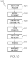
FIG. 10 is a flow diagram of an aircraft manufacturing and service methodology; and -
FIG. 11 is a schematic illustration of an aircraft. - The following detailed description refers to the accompanying drawings, which illustrate specific examples described by the present disclosure. Other examples having different structures and operations do not depart from the scope of the present disclosure. Like reference numerals may refer to the same feature, element, or component in the different drawings.
- Illustrative, non-exhaustive examples, which may be, but are not necessarily, claimed, of the subject matter according to the present disclosure are provided below. Reference herein to "example" means that one or more feature, structure, element, component, characteristic, and/or operational step described in connection with the example is included in at least one aspect, embodiment, and/or implementation of the subject matter according to the present disclosure. Thus, the phrases "an example," "another example," "one or more examples," and similar language throughout the present disclosure may, but do not necessarily, refer to the same example. Further, the subject matter characterizing any one example may, but does not necessarily, include the subject matter characterizing any other example. Moreover, the subject matter characterizing any one example may be, but is not necessarily, combined with the subject matter characterizing any other example.
- As used herein, a system, apparatus, device, structure, article, element, component, or hardware "configured to" perform a specified function is indeed capable of performing the specified function without any alteration, rather than merely having potential to perform the specified function after further modification. In other words, the system, apparatus, device, structure, article, element, component, or hardware "configured to" perform a specified function is specifically selected, created, implemented, utilized, programmed, and/or designed for the purpose of performing the specified function. As used herein, "configured to" denotes existing characteristics of a system, apparatus, structure, article, element, component, or hardware that enable the system, apparatus, structure, article, element, component, or hardware to perform the specified function without further modification. For purposes of this disclosure, a system, apparatus, device, structure, article, element, component, or hardware described as being "configured to" perform a particular function may additionally or alternatively be described as being "adapted to" and/or as being "operative to" perform that function.
- For the purpose of this disclosure, the terms "coupled," "coupling," and similar terms refer to two or more elements that are joined, linked, fastened, attached, connected, put in communication, or otherwise associated (e.g., mechanically, electrically, fluidly, optically, electromagnetically) with one another. In various examples, the elements may be associated directly or indirectly. As an example, element A may be directly associated with element B. As another example, element A may be indirectly associated with element B, for example, via another element C. It will be understood that not all associations among the various disclosed elements are necessarily represented. Accordingly, couplings other than those depicted in the figures may also exist.
- References throughout the present specification to features, advantages, or similar language used herein do not imply that all of the features and advantages that may be realized with the examples disclosed herein should be, or are in, any single example. Rather, language referring to the features and advantages is understood to mean that a specific feature, advantage, or characteristic described in connection with an example is included in at least one example. Thus, discussion of features, advantages, and similar language used throughout the present disclosure may, but do not necessarily, refer to the same example.
- Referring generally to
FIGs. 1-8 , disclosed is ablind fastener 100. Theblind fastener 100 includes asleeve 110 and acore bolt 120. Theblind fastener 100 is configured to couple at least two components to form astructure 210 via radial expansion of thesleeve 110 upon movement of thecore bolt 120 relative to thesleeve 110. Theblind fastener 100 may be generally cylindrical in shape, although other shapes and configurations may be implemented. - Referring to
FIG. 1 , in one or more examples, theblind fastener 100 includes acore bolt 120 at least partially received in abore 160 of thesleeve 110. Thecore bolt 120 defines a core bolt axis AC and includes abody 122 having adistal end portion 122a andproximal end portion 122b axially opposed from thedistal end portion 122a. In one example, thebody 122 is tapered from thedistal end portion 122a of thebody 122 to theproximal end portion 122b of thebody 122. The tapered shape of thebody 122 causes radial expansion of thesleeve 110 when thebody 122 is urged relative to thesleeve 110 through thebore 160 of thesleeve 110 along the core axis AC. - Referring to
FIG. 1 , the taper from thedistal end portion 122a of thebody 122 to theproximal end portion 122b of thebody 122 is a continuous taper. Referring toFIG. 3 , in one example, the continuous taper of thebody 122 has a taper angle ΘC defined as the angle between the core bolt axis Ac and a bolt plane defined in the drawings as a bolt line, L1, coincident with anoutside surface 126 of thebody 122 of thecore bolt 120. In on example, the angle ΘC ranges from about 1 degree to about 20 degrees. In another example, the continuous taper has a taper angle ΘC ranges from about 2 degrees to about 10 degrees. - In another example, the taper from the
distal end portion 122a of thebody 122 to theproximal end portion 122b of thebody 122 is a discontinuous taper. For example, the taper from thedistal end portion 122a of thebody 122 to theproximal end portion 122b of thebody 122 may vary such that it is increased at any portion along thebody 122 to facilitate breaking near theneck 150 of thecore bolt 120. - Referring to
FIG. 5 , in one or more examples, thebody 122 of thecore bolt 120 is a truncated conical body having a diameter D. The diameter D of the truncated conical body proximate thedistal end portion 122a of thebody 122, D1, may be greater than the diameter of the truncated conical body proximate theproximal end portion 122b, D2. Further, as illustrated inFIG. 5 , thesleeve 110 may be countersunk such that it is chamfered to complement the receivedcore bolt 120. - Referring to
FIG. 6 , in one or more examples, thebody 122 of thecore bolt 120 includes aflanged portion 124 at theproximal end portion 122b. Theflanged portion 124 is configured to swage upon installation of theblind fastener 100 into astructure 210, seeFIG. 8 . Theflanged portion 124 of thecore bolt 120 may be formed by aflange forming tool 410. In one example, theflanged portion 124 of thecore bolt 120 is formed by theflange forming tool 410 as thecore bolt 120 is pulled up. In another example, theflange forming tool 410 may spin and/or turn and roll theflanged portion 124 of thecore bolt 120 to maintain thecore bolt 120 in a desired position. - The
body 122 causes radial expansion of thesleeve 110 when thebody 122 of thecore bolt 120 moves along the core bolt axis Ac relative to thesleeve 110 and into thesleeve 110. The radial expansion ofsleeve 110 facilitates maintaining theblind fastener 100 in a desired position within astructure 210. - Referring to
FIG. 6 , in one or more examples, theblind fastener 100 includes astem 130.Stem 130 may be connected to theproximal end portion 122b of thebody 122. In one example, thestem 130 includes at least onegroove 131. Groove 131 may be annular, notched, or any other configuration for coupling with a tool. Referring toFIG. 1 , in another example, thestem 130 includes acollared portion 133. - Referring to
FIG. 1 , in one or more examples, theblind fastener 100 includes aneck 150 abutting theproximal end portion 122b positioned between thebody 122 and thestem 130. Theneck 150 may be configured to break apart from thecore bolt 120 upon being pulled along the core bolt axis AC as thecore bolt 120 moves, concurrently applying axial force to thesleeve 110, resulting in radial expansion. In one example, theneck 150 is substantially cylindrical and has a diameter that is smaller than a diameter proximate theproximal end portion 122b of thecore bolt 120, D2. - Referring to
FIG. 1 , in one or more examples, theblind fastener 100 may include acap 140. In one example, thecap 140 is integral with thecore bolt 120. In another example, thecap 140 is threadedly engageable with thecore bolt 120, seeFIGs. 6-8 . Thecap 140 may be substantially flush with aninner surface 220 of thestructure 210 upon installation. In another example, thecap 140 may be offset from theinner surface 220 of thestructure 210 upon installation. For example, thecap 140 may abut theinner surface 220 of thestructure 210 or, in another example, thesleeve 110 may buckle along aflanged portion 115 and form a lip along theinner surface 220 between thecap 140 and thestructure 210, seeFIG. 8 . - Referring to
FIG. 2 , in one or more example,sleeve 110 has adistal end portion 110a and aproximal end portion 110b.Sleeve 110 further defines abore 160 configured to receivecore bolt 120. In one example,sleeve 110 defines a sleeve axis As. Thebore 160 of thesleeve 110 is tapered from thedistal end portion 110a to theproximal end portion 110b of thesleeve 110. The taper may be continuous from thedistal end portion 110a to theproximal end portion 110b. The continuous taper of thesleeve 110 may be substantially the same as the continuous taper of thecore bolt 120. - Still referring to
FIG. 2 , in one or more examples, the continuous taper of thesleeve 110 has a sleeve taper angle ΘS that is defined by the angle between a sleeve axis As and a sleeve plane defined in the drawings as a sleeve line, L2, coincident with aninside surface 112 of thesleeve 110. In one example, the continuous taper has a sleeve taper angle ΘS ranging from about 1 degree to about 20 degrees. In another example, the continuous taper has a sleeve taper angle ΘS ranging from about 2 degrees to about 10 degrees. In yet another example, referring toFIG. 4 , the continuous taper has a sleeve taper angle ΘS that is substantially the same as a taper angle ΘC of thecore bolt 120. - Referring to
FIG. 6 andFIG. 7 , thesleeve 110 may include aflanged portion 115 at thedistal end portion 110a. Theflanged portion 115 may be sized and shaped to receive thedistal end portion 122a of thebody 122 of thecore bolt 120 and thecap 140 of theblind fastener 100. For example, thecap 140 may be similarly chamfered to mate with theflanged portion 115 of thesleeve 110. Theflanged portion 115 of thesleeve 110 may swage over theinner surface 220 of thestructure 210 upon pulling of thecore bolt 120 along the core bolt axis AC for retention of theblind fastener 100 upon installation, seeFIG. 8 . - Referring to
FIG.6-FTG. 8 , in one or more examples, thesleeve 110 may have a lowerflanged portion 117. In one example, the lowerflanged portion 117 is chamfered. The lowerflanged portion 117 may be sized and shaped to accommodate aflanged portion 124 of thecore bolt 120 upon installation of theblind fastener 100. Similarly, thesleeve 110 may be a protruding head sleeve, seeFIG. 8 . - In one non-limiting example, the
blind fastener 100 includes asleeve 110 having adistal end portion 110a and aproximal end portion 110b. Thesleeve 110 defines abore 160. Thebore 160 is tapered from thedistal end portion 110a to theproximal end portion 110b. Thesleeve 110 includes a first metallic material. - The
blind fastener 100 further includes acore bolt 120 at least partially received in thebore 160 of thesleeve 110. Thecore bolt 120 includes a second metallic material and defines a core bolt axis AC. The first metallic material has a hardness that is substantially softer than the hardness of the second metallic material. Thecore bolt 120 includes abody 122 having adistal end portion 122a and aproximal end portion 122b axially opposed from thedistal end portion 122a. Thebody 122 is tapered from thedistal end portion 122a of thebody 122 to theproximal end portion 122b of thebody 122. Theblind fastener 100 further includes astem 130 connected to theproximal end portion 122b of thebody 122. - In one or more examples, the
core bolt 120 ofblind fastener 100 includes a second metallic material and thesleeve 110 includes a first metallic material. In one example, the first metallic material is substantially different from the second metallic material. The first metallic material may have a hardness that is different than a hardness of the second metallic material. The first metallic material may be at least 5% softer than the second metallic material. In another example, the first metallic material may be at least 10% softer than the second metallic material. The materials of thecore bolt 120 andsleeve 110 of thefastener 100 may be selected based upon one or more desired material properties, such as hardness, tensile strength, elongation, yield strength, and the like. Material hardness, for example, may be measured by Brinell, Rockwell, Vickers, or any other suitable means of determining material hardness. Material hardness may change based upon the material composition used for each component of theblind fastener 100. - In one example, the first metallic material includes a ferrous metal. In another example, the first metallic material includes a non-ferrous metal. In yet another example, the first metallic material may include one or more of titanium, aluminum, copper, bronze, beryllium, nickel, tin, steel, or any combination thereof. In one example, the first metallic material is corrosion resistant. In another example, the first metallic material provides electromagnetic energy (EME) protection. In one non-limiting example, the
blind fastener 100 includes Inconel™. The use of non-metallic materials is also contemplated and such use will not result in a departure from the scope of the present disclosure. - In one example, the second metallic material includes a ferrous metal. In another example, the second metallic material includes a non-ferrous metal. In yet another example, the second metallic material may include one or more of titanium, aluminum, copper, bronze, beryllium, nickel, tin, steel, or any combination thereof. In one example, the second metallic material is corrosion resistant. In another example, the second metallic material provides EME protection. In one non-limiting example, the second metallic material includes Inconel™. The use of non-metallic materials is also contemplated and such use will not result in a departure from the scope of the present disclosure.
- Referring to
FIG. 9 , in one or more examples, disclosed is amethod 300 for installing ablind fastener 100, as shown and described herein, into abore 200 in astructure 210. Theblind fastener 100 includes asleeve 110 and acore bolt 120 at least partially received within thesleeve 110, thecore bolt 120 defining a core bolt axis Ac, seeFIG. 1 . - Referring to
FIG. 9 , themethod 300 includes inserting 310 theblind fastener 100 into thebore 200 of thestructure 210. In one example, the inserting 310 includes inserting both thesleeve 110 andcore bolt 120 simultaneously into thebore 200 of thestructure 210. The inserting 310 engages thestructure 210 from just one side, without the need for accessing the opposing side of thestructure 210. The inserting 310 may be performed manually, may be automated, or a combination thereof. - Still referring to
FIG. 9 , themethod 300 includes applying 320 an axial force to thesleeve 110 to immobilize the sleeve relative to thestructure 210. In one example, themethod 300 incudes, during the applying 320, pulling 340 thecore bolt 120 relative to thesleeve 110 to cause radial expansion of thesleeve 110. The pulling 340 may be performed manually, may be automated, or a combination thereof. - The pulling 340 may be achieved, for example, by operatively coupling a
tool 400 to thecore bolt 120, thetool 400 configured to pull thecore bolt 120 along the core bolt axis Ac. Thetool 400 may include any movement mechanism, such as an actuator, configured to pull thecore bolt 120 along the core bolt axis Ac. Applying 320 axial force occurs simultaneously with the pulling 340 as thetapered core bolt 120 moves along the core bolt axis AC and presses against thesleeve 110 intostructure 210. - In one example, the
core bolt 120 includes astem 130 and themethod 300 includes gripping 330 thecore bolt 120 prior to the pulling 340. The gripping 330 may be performed manually, may be automated, or a combination thereof. The gripping 330 may include moving atool 400 into engagement with thestem 130 of theblind fastener 100. In one example, thetool 400 includes alocking collar 420 configured to engage with thestem 130 of theblind fastener 100. Thestem 130 may include agroove 131, acollared portion 133, or any other feature to facilitate engagement of thetool 400, or lockingcollar 420, with theblind fastener 100. Thelocking collar 420 may be operatively coupled with a movement mechanism of thetool 400, such as an actuator, configured to pull thelocking collar 420 along the core bolt axis Ac. - In one or more examples, the
core bolt 120 of theblind fastener 100 includes acap 140. Thecap 140 protruded from thestructure 210 after the pulling 340, seeFIG. 8 . In another example, thecap 140 may abut the buckled portion of thesleeve 110 along theinner surface 220 of thestructure 210 after the pulling 340, upon installation. In yet another example, thecap 140 is substantially flush with aninner surface 220 of thestructure 210 after the pulling 340, seeFIG. 5 . - Examples of the subject matter disclosed herein may be described in the context of aircraft manufacturing and
service method 1100 as shown inFIG. 10 andaircraft 1102 as shown inFIG. 11 . During pre-production, themethod 1100 may include specification and design (block 1104) ofaircraft 1102 and material procurement (block 1106). During production, component and subassembly manufacturing (block 1108) and system integration (block 1110) ofaircraft 1102 may take place. Thereafter,aircraft 1102 may go through certification and delivery (block 1112) to be placed in service (block 1114). While in service,aircraft 1102 may be scheduled for routine maintenance and service (block 1116). Routine maintenance and service may include modification, reconfiguration, refurbishment, etc. of one or more systems ofaircraft 1102. - Each of the processes of the
method 1100 may be performed or carried out by a system integrator, a third party, and/or an operator (e.g., a customer). For the purposes of this description, a system integrator may include, without limitation, any number of aircraft manufacturers and major-system subcontractors; a third party may include, without limitation, any number of vendors, subcontractors, and suppliers; and an operator may be an airline, leasing company, military entity, service organization, and so on. - As shown in
FIG. 11 ,aircraft 1102 produced by themethod 1100 may includeairframe 1118 with a plurality of high-level systems 1120 and interior 1122. Examples of high-level systems 1120 include one or more ofpropulsion system 1124,electrical system 1126,hydraulic system 1128, andenvironmental system 1130. Any number of other systems may be included. Although an aerospace example is shown, the principles disclosed herein may be applied to other industries, such as the automotive industry. Accordingly, in addition toaircraft 1102, the principles disclosed herein may apply to other vehicles, e.g., land vehicles, marine vehicles, space vehicles, etc. - The disclosed blind fasteners and associated methods for installing blind fasteners shown or described herein may be employed during any one or more of the stages of the
method 1100. For example, components or subassemblies corresponding to component and subassembly manufacturing (block 1108) may be fabricated or manufactured in a manner similar to components or subassemblies produced whileaircraft 1102 is in service (block 1114). - Also, one or more examples of the systems, methods, or combination thereof may be utilized during production stages (block 1108 and block 1110), for example, by substantially expediting assembly of or reducing the cost of
aircraft 1102. Similarly, one or more examples of the systems or method realizations, or a combination thereof, may be utilized, for example and without limitation, whileaircraft 1102 is in service (block 1114) and/or during maintenance and service (block 1116). - The disclosed blind fasteners and associated methods for installing blind fasteners are described in the context of an aircraft. However, one of ordinary skill in the art will readily recognize that the disclosed blind fasteners and associated methods for installing blind fasteners may be utilized for a variety of applications. For example, the disclosed blind fasteners and associated methods for installing blind fasteners may be implemented in various types of vehicles including, e.g., helicopters, watercraft, passenger ships, automobiles, and the like.
- Although various examples of the disclosed blind fasteners and associated methods for installing blind fasteners have been shown and described, modifications may occur to those skilled in the art upon reading the specification. The present application includes such modifications and is limited only by the scope of the claims.
- Further, the disclosure comprises examples according to the following clauses:
- Clause 1. A blind fastener comprising:
- a sleeve comprising a distal end portion and a proximal end portion, and defining a bore; and
- a core bolt at least partially received in the bore of the sleeve, the core bolt defining a core bolt axis and comprising a body having a distal end portion and a proximal end portion axially opposed from the distal end portion, wherein the body is tapered from the distal end portion of the body to the proximal end portion of the body such that the core bolt causes radial expansion of the sleeve when the body is urged relative to the sleeve through the bore along the core bolt axis.
- Clause 2. The blind fastener of Clause 1, wherein the taper from the distal end portion of the body to the proximal end portion of the body is a continuous taper.
- Clause 3. The blind fastener of Clause 2, wherein the continuous taper has a taper angle ranging from about 1 degree to about 20 degrees.
- Clause 4. The blind fastener of Clause 2, wherein the continuous taper has a taper angle ranging from about 2 degrees to about 10 degrees.
- Clause 5. The blind fastener of any preceding Clause, wherein the body is a truncated conical body.
- Clause 6. The blind fastener of Clause 5, wherein a diameter of the truncated conical body proximate the distal end portion of the body is greater than the diameter of the truncated conical body proximate the proximal end portion.
- Clause 7. The blind fastener of any preceding Clause, wherein the body of the core bolt comprises a flanged portion at the proximal end portion.
- Clause 8. The blind fastener of any preceding Clause, further comprising a stem connected to the proximal end portion of the body.
- Clause 9. The blind fastener of Clause 8, wherein the stem comprises at least one groove.
- Clause 10. The blind fastener of Clause 8 or Clause 9, wherein the stem comprises a collared portion.
- Clause 11. The blind fastener according to any of Clauses 8 to 10, further comprising a neck abutting the proximal end portion positioned between the body and the stem.
- Clause 12. The blind fastener of any preceding Clause, wherein the core bolt comprises a second metallic material and the sleeve comprises a first metallic material, and wherein the first metallic material is substantially different from the second metallic material.
- Clause 13. The blind fastener of Clause 12, wherein the first metallic material is at least 5% softer than the second metallic material.
- Clause 14. The blind fastener of any preceding Clause, wherein the core bolt comprises titanium.
- Clause 15. The blind fastener of any preceding Clause, wherein the sleeve comprises a ferrous metal.
- Clause 16. The blind fastener according to any of Clauses 1 to 14, wherein the sleeve comprises a non-ferrous metal.
- Clause 17. The blind fastener of any preceding Clause, wherein the sleeve defines a sleeve axis.
- Clause 18. The blind fastener of any preceding Clause, wherein the sleeve comprises a flanged portion at the distal end portion.
- Clause 19. The blind fastener of any preceding Clause, wherein the bore is tapered from the distal end portion to the proximal end portion.
- Clause 20. The blind fastener of Clause 19, wherein the taper is continuous.
- Clause 21. The blind fastener of Clause 19 or Clause 20, wherein the taper has a sleeve taper angle ranging from about 1 degree to about 20 degrees.
- Clause 22. The blind fastener of Clause 19 or Clause 20, wherein the taper has a sleeve taper angle ranging from about 2 degrees to about 10 degrees.
- Clause 23. The blind fastener of Clause 19 or Clause 20, wherein the taper has a sleeve taper angle that is substantially the same as a taper angle of the core bolt.
- Clause 24. The blind fastener of any preceding Clause, further comprising a cap.
- Clause 25. The blind fastener of Clause 24, wherein the cap is integral with the core bolt.
- Clause 26. The blind fastener of Clause 24, wherein the cap is threadedly engageable with the core bolt.
- Clause 27. A blind fastener comprising:
- a sleeve comprising a distal end portion and a proximal end portion, and defining a bore, the bore being tapered from the distal end portion to the proximal end portion, the sleeve comprising a first metallic material; and
- a core bolt at least partially received in the bore of the sleeve, the core bolt comprising a second metallic material and defining a core bolt axis, wherein the first metallic material is substantially softer than the second metallic material, the core bolt comprising:
- a body having a distal end portion and a proximal end portion axially opposed from the distal end portion, wherein the body is tapered from the distal end portion of the body to the proximal end portion of the body; and
- a stem connected to the proximal end portion of the body.
- Clause 28. A method for installing a blind fastener into a bore in a structure, the blind fastener comprising a sleeve and a core bolt at least partially received within the sleeve, the core bolt defining a core bolt axis, the method comprising:
- inserting the blind fastener into the bore; and
- pulling the core bolt relative to the sleeve to cause radial expansion of the sleeve.
- Clause 29. The method of Clause 28, further comprising, during the pulling, applying an axial force to the sleeve to immobilize the sleeve relative to the structure.
- Clause 30. The method of Clause 28 or Clause 29, further comprising gripping the core bolt prior to the pulling.
- Clause 31. The method of Clause 30, wherein the core bolt comprises a stem and wherein the gripping comprises moving a locking collar into engagement with the stem.
- Clause 32. The method according to any of Clauses 28 to 31, wherein the core bolt comprises a cap.
- Clause 33. The method of Clause 32, wherein the cap protrudes from the structure after the pulling.
- Clause 34. The method of Clause 32, where in the cap is substantially flush with an inner surface of the structure after the pulling.
- Clause 35. A method for installing a blind fastener according to any of Clauses 1 to 27 into a bore in a structure, the method comprising:
- inserting the blind fastener into the bore (200); and
- pulling the core bolt relative to the sleeve to cause radial expansion of the sleeve.
Claims (15)
- A blind fastener (100) comprising:a sleeve (110) comprising a distal end portion (110a) and a proximal end portion (110b), and defining a bore (160); anda core bolt (120) at least partially received in the bore (160) of the sleeve (110), the core bolt (120) defining a core bolt axis (AC) and comprising a body (122) having a distal end portion (122a) and a proximal end portion (122b) axially opposed from the distal end portion (122a), wherein the body (122) is tapered from the distal end portion (122a) of the body (122) to the proximal end portion (122b) of the body (122) such that the core bolt (120) causes radial expansion of the sleeve (110) when the body (122) is urged relative to the sleeve (110) through the bore (160) along the core bolt axis (Ac).
- The blind fastener (100) of Claim 1, wherein the taper from the distal end portion (122a) of the body (122) to the proximal end portion (122b) of the body (122) is a continuous taper;
wherein the continuous taper optionally has a taper angle (ΘC) ranging from about 1 degree to about 20 degrees, for example ranging from about 2 degrees to about 10 degrees. - The blind fastener (100) of Claim 1 or Claim 2, wherein the body (122) is a truncated conical body, and
wherein a diameter of the truncated conical body proximate the distal end portion (122a) of the body (122) is optionally greater than the diameter of the truncated conical body proximate the proximal end portion (122b). - The blind fastener (100) of any preceding Claim, wherein the body (122) of the core bolt (120) comprises a flanged portion (124) at the proximal end portion (122b).
- The blind fastener (100) of any preceding Claim, further comprising a stem (130) connected to the proximal end portion (122b) of the body (122);wherein the stem (130) optionally comprises at least one groove (131), and/orwherein the stem (130) comprises a collared portion (133), and/oroptionally further comprising a neck (150) abutting the proximal end portion (122b) positioned between the body (122) and the stem (130).
- The blind fastener (100) of any preceding Claim, wherein the core bolt (120) comprises a second metallic material and the sleeve (110) comprises a first metallic material, and wherein the first metallic material is substantially different from the second metallic material; wherein the first metallic material is optionally at least 5% softer than the second metallic material.
- The blind fastener (100) of any preceding Claim, wherein the sleeve (110) comprises a flanged portion (115) at the distal end portion (110a).
- The blind fastener (100) of any preceding Claim, wherein the bore (160) is tapered from the distal end portion (110a) to the proximal end portion (110b);wherein the taper is continuous; and/orwherein the taper has a sleeve taper angle (ΘS) ranging from about 1 degree to about 20 degrees; and/orwherein the taper has a sleeve taper angle (ΘS) ranging from about 2 degree to about 10 degrees; and/orwherein the taper has a sleeve taper angle (ΘS) that is substantially the same as a taper angle (ΘC) of the core bolt (120).
- The blind fastener of any preceding Claim, further comprising a cap (140);wherein the cap (140) is integral with the core bolt (120); orwherein the cap (140) is threadedly engageable with the core bolt (120).
- A method (300) for installing a blind fastener (100) into a bore (200) in a structure (210), the blind fastener (100) comprising a sleeve (110) and a core bolt (120) at least partially received within the sleeve (110), the core bolt (120) defining a core bolt axis (Ac), the method (300) comprising:inserting (310) the blind fastener (100) into the bore (200); andpulling (340) the core bolt (120) relative to the sleeve (110) to cause radial expansion of the sleeve (110).
- The method of claim 10, wherein the core bolt comprises a body (122) having a distal end portion (122a) and a proximal end portion (122b) axially opposed from the distal end portion (122a), wherein the body (122) is tapered from the distal end portion (122a) of the body (122) to the proximal end portion (122b) of the body (122).
- The method (300) of Claim 10 or claim 11, further comprising, during the pulling (340), applying (320) an axial force to the sleeve (110) to immobilize the sleeve relative to the structure (210).
- The method (300) according to any of Claims 10 to 12, further comprising gripping (330) the core bolt (120) prior to the pulling (340);
wherein the core bolt (120) optionally comprises a stem (130) and wherein the gripping (330) optionally comprises moving a locking collar (420) into engagement with the stem (130). - The method (300) according to any of Claims 10 to 13, wherein the core bolt (120) comprises a cap (140).
- The method (300) of Claim 14, wherein the cap (140) protrudes from the structure (210) after the pulling (340); or
wherein the cap (140) is substantially flush with an inner surface (220) of the structure (210) after the pulling (340).
Applications Claiming Priority (1)
| Application Number | Priority Date | Filing Date | Title |
|---|---|---|---|
| US17/471,372 US20230083921A1 (en) | 2021-09-10 | 2021-09-10 | Blind fasteners and associated methods for installing blind fasteners |
Publications (1)
| Publication Number | Publication Date |
|---|---|
| EP4148287A1 true EP4148287A1 (en) | 2023-03-15 |
Family
ID=83152023
Family Applications (1)
| Application Number | Title | Priority Date | Filing Date |
|---|---|---|---|
| EP22193076.1A Pending EP4148287A1 (en) | 2021-09-10 | 2022-08-31 | Blind fasteners and associated methods for installing blind fasteners |
Country Status (4)
| Country | Link |
|---|---|
| US (1) | US20230083921A1 (en) |
| EP (1) | EP4148287A1 (en) |
| AU (1) | AU2022203730A1 (en) |
| CA (1) | CA3158671A1 (en) |
Citations (5)
| Publication number | Priority date | Publication date | Assignee | Title |
|---|---|---|---|---|
| GB642770A (en) * | 1947-12-19 | 1950-09-13 | Blackburn Aircraft Ltd | A rivet for use in riveting into a blind hole |
| GB1333893A (en) * | 1971-06-02 | 1973-10-17 | Olin Corp | Anchor bolt assemblies |
| DE3409373A1 (en) * | 1984-03-14 | 1985-09-19 | Alfred Honsel Nieten - und Metallwarenfabrik GmbH & Co, 5758 Fröndenberg | Anchoring element |
| DE202016103068U1 (en) * | 2016-06-09 | 2016-07-11 | Arnold Ag | Blind fastening device for fastening a component |
| WO2020077396A1 (en) * | 2018-10-15 | 2020-04-23 | Nord-Lock Switzerland Gmbh | Hydraulic tensioning and release tool for expansion fasteners |
Family Cites Families (60)
| Publication number | Priority date | Publication date | Assignee | Title |
|---|---|---|---|---|
| US2803984A (en) * | 1954-03-09 | 1957-08-27 | Harry H Swenson | Blind rivet having longitudinally ribbed and hardened sleeve end |
| US3026761A (en) * | 1959-06-04 | 1962-03-27 | Carel T Torresen | Retractable blind bolt having radially contractable and expandable work engaging means |
| US3272060A (en) * | 1964-04-24 | 1966-09-13 | Louis H Morin | Plastic blind rivet |
| US3298725A (en) * | 1964-10-01 | 1967-01-17 | John C Boteler | High-strength fastener |
| US3443474A (en) * | 1967-12-27 | 1969-05-13 | Vsi Corp | Blind fastener |
| US3643544A (en) * | 1969-02-27 | 1972-02-22 | Nat Screw & Mfg Co The | High-strength structural blind fastener for use in airplanes, rockets and the like |
| US3515028A (en) * | 1969-03-21 | 1970-06-02 | Huck Mfg Co | Blind fastener |
| US3653294A (en) * | 1969-06-27 | 1972-04-04 | Edgar F Nason | Blind fastener |
| US3835615A (en) * | 1970-04-30 | 1974-09-17 | J King | Fastener joint construction |
| US3702088A (en) * | 1971-03-31 | 1972-11-07 | Boeing Co | Double shank blind bolt |
| US3918130A (en) * | 1974-01-25 | 1975-11-11 | Hartwell Corp | Initially one piece removable fastener |
| US4026187A (en) * | 1975-12-05 | 1977-05-31 | Illinois Tool Works Inc. | Plastic screw grommet |
| JPS6042014B2 (en) * | 1978-02-28 | 1985-09-19 | 株式会社ニフコ | How to form blind rivets |
| US4595324A (en) * | 1982-09-28 | 1986-06-17 | Monogram Industries, Inc. | Impulse resistant blind fastener |
| GB8315077D0 (en) * | 1983-06-01 | 1983-07-06 | Avdel Ltd | Threaded fastener |
| US4659271A (en) * | 1984-02-23 | 1987-04-21 | Monogram Industries, Inc. | Flush break blind fastener |
| US5066179A (en) * | 1984-02-23 | 1991-11-19 | Mag Aerospace Industries, Inc. | Blind fastener |
| US4967463A (en) * | 1984-02-23 | 1990-11-06 | Mag Aerospace Industries, Inc. | Method of fastening panels using drive nut blind fasteners |
| US4772167A (en) * | 1986-05-07 | 1988-09-20 | Monogram Industries, Inc. | Blind fastener with deformable drive nut |
| US4747738A (en) * | 1986-10-03 | 1988-05-31 | Avilbank Mfg., Inc. | Captive panel fastener assembly |
| US5141373A (en) * | 1990-08-15 | 1992-08-25 | Kendall James W | Flush breaking interference fit blind fastener |
| US5123792A (en) * | 1991-01-24 | 1992-06-23 | Sps Technologies, Inc. | Blind fastener with washer for composite material |
| US5152648A (en) * | 1991-11-06 | 1992-10-06 | Textron Inc. | Blind fastener for composite materials |
| US5163795A (en) * | 1992-04-09 | 1992-11-17 | Illionis Tool Works, Inc. | Front mounted rivet with interlocked drive pin |
| GB2269873A (en) * | 1992-08-21 | 1994-02-23 | Avdel Systems Ltd | Self-plugging blind fastener |
| US5399053A (en) * | 1993-04-27 | 1995-03-21 | Avibank Mfg., Inc. | Quick action panel fastener assembly including a cup enclosed retainer receiving a bolt therein |
| US5746556A (en) * | 1995-03-13 | 1998-05-05 | Kabushiki Kaisha Youma Kohboh | Anchor unit with expansive anchor member expanded by utilizing turning force of bolt |
| US5816761A (en) * | 1996-01-11 | 1998-10-06 | The Boeing Company | Lightweight structural blind fastener |
| US5810530A (en) * | 1997-10-08 | 1998-09-22 | Huck International, Inc. | Interference blind type bolt |
| US6186717B1 (en) * | 1999-04-28 | 2001-02-13 | Fairchild Holding Corp | Electrical terminal blind grounding stud fastener system |
| US6454502B1 (en) * | 2000-09-13 | 2002-09-24 | Fairchild Holding Corp. | Blind fastener and drive nut assembly |
| US6676347B2 (en) * | 2000-09-13 | 2004-01-13 | Huck Patents, Inc. | Blind fastener and drive nut assembly |
| US6862864B2 (en) * | 2001-06-21 | 2005-03-08 | Black & Decker Inc. | Method and apparatus for fastening steel framing members |
| US20030123947A1 (en) * | 2001-12-27 | 2003-07-03 | Soheil Eshraghi | Blind rivet with hollow head |
| US6868757B2 (en) * | 2003-05-20 | 2005-03-22 | Huck International, Inc. | Blind fastener and nose assembly for installation of the blind fastener |
| US20050163586A1 (en) * | 2004-01-05 | 2005-07-28 | Tamashiro Emory K. | Flush break-off blind bolt |
| US7677852B2 (en) * | 2004-08-30 | 2010-03-16 | Acument Intellectual Properties, Llc | Multi-lobular lockbolt |
| US7555820B2 (en) * | 2005-01-24 | 2009-07-07 | The Boeing Company | Methods for removing blind fasteners |
| FR2882797B1 (en) * | 2005-03-02 | 2007-05-25 | Itw De France Soc Par Actions | ATTACHMENT ADAPTED TO BE FIXED IN A PREDETERMINE CONTOUR CAVITY |
| GB2427008B (en) * | 2005-06-10 | 2008-05-14 | Newfrey Llc | Improved blind rivet |
| CA2643034A1 (en) * | 2006-02-28 | 2007-09-07 | Monogram Aerospace Fasteners, Inc. | Mechanically locked blind bolt fastener |
| US20080060192A1 (en) * | 2006-07-13 | 2008-03-13 | Sps Technologies, Llc | High performance nosepiece for blind bolt installation |
| FR2904385B1 (en) * | 2006-07-25 | 2008-09-05 | Garonne Ets Auriol & Cie | STRUCTURAL FIXING METHOD BY BLIND RIVET, BLIND RIVET FOR CARRYING OUT SAME, AND POSITIONING TOOL ADJUSTED TO SUCH A RIVET |
| GB2464674C (en) * | 2008-10-20 | 2013-04-03 | Avdel Uk Ltd | Blind fastener |
| WO2010111593A2 (en) * | 2009-03-27 | 2010-09-30 | Monogram Aerospace Fasteners, Inc. | Blind bolt fastener |
| WO2011050040A1 (en) * | 2009-10-22 | 2011-04-28 | Alcoa Inc. | Enhanced conductivity sleeved fastener and method for making same |
| US8529177B2 (en) * | 2010-02-15 | 2013-09-10 | Polaris Fastening Consulting, Llc | Integrated pin/sleeve blind fastener |
| WO2012142033A2 (en) * | 2011-04-14 | 2012-10-18 | Pratt John D | Fastener and method of installing same |
| DE102011055724A1 (en) * | 2011-11-25 | 2013-05-29 | Newfrey Llc | rivet bolts |
| US9284971B2 (en) * | 2012-04-04 | 2016-03-15 | John D. Pratt | Fastener and method of installing same |
| US9593706B2 (en) * | 2012-11-11 | 2017-03-14 | The Boeing Company | Structural blind fastener and method of installation |
| CN203516322U (en) * | 2013-07-02 | 2014-04-02 | J·D·普拉特 | Fastener |
| US9714676B2 (en) * | 2014-08-07 | 2017-07-25 | The Boeing Company | Hole-filling sleeve and washer design for bolt installation |
| ES2777655T3 (en) * | 2016-03-18 | 2020-08-05 | Monogram Aerospace Fasteners Inc | Blind fixing element |
| US10760605B2 (en) * | 2016-03-18 | 2020-09-01 | Monogram Aerospace Fasteners, Inc. | Blind fastener |
| WO2018075428A1 (en) * | 2016-10-20 | 2018-04-26 | Arconic Inc. | Fastener and fastening system |
| US10396493B2 (en) * | 2017-09-06 | 2019-08-27 | Hirel Connectors, Inc. | Electrical connector with pull release |
| US10774863B2 (en) * | 2018-06-18 | 2020-09-15 | The Boeing Company | Blind fastener system with electromagnetic effects-protective coating |
| US11421724B2 (en) * | 2018-08-10 | 2022-08-23 | Monogram Aerospace Fasteners, Inc. | Flush-break blind fastener |
| US11137014B2 (en) * | 2019-01-08 | 2021-10-05 | The Boeing Company | Conductive fastening system and method for improved EME performance |
-
2021
- 2021-09-10 US US17/471,372 patent/US20230083921A1/en active Pending
-
2022
- 2022-05-09 CA CA3158671A patent/CA3158671A1/en active Pending
- 2022-05-31 AU AU2022203730A patent/AU2022203730A1/en active Pending
- 2022-08-31 EP EP22193076.1A patent/EP4148287A1/en active Pending
Patent Citations (5)
| Publication number | Priority date | Publication date | Assignee | Title |
|---|---|---|---|---|
| GB642770A (en) * | 1947-12-19 | 1950-09-13 | Blackburn Aircraft Ltd | A rivet for use in riveting into a blind hole |
| GB1333893A (en) * | 1971-06-02 | 1973-10-17 | Olin Corp | Anchor bolt assemblies |
| DE3409373A1 (en) * | 1984-03-14 | 1985-09-19 | Alfred Honsel Nieten - und Metallwarenfabrik GmbH & Co, 5758 Fröndenberg | Anchoring element |
| DE202016103068U1 (en) * | 2016-06-09 | 2016-07-11 | Arnold Ag | Blind fastening device for fastening a component |
| WO2020077396A1 (en) * | 2018-10-15 | 2020-04-23 | Nord-Lock Switzerland Gmbh | Hydraulic tensioning and release tool for expansion fasteners |
Also Published As
| Publication number | Publication date |
|---|---|
| CA3158671A1 (en) | 2023-03-10 |
| US20230083921A1 (en) | 2023-03-16 |
| AU2022203730A1 (en) | 2023-03-30 |
Similar Documents
| Publication | Publication Date | Title |
|---|---|---|
| US10294976B2 (en) | Method of installing a structural blind fastener | |
| EP3584289B1 (en) | Blind fastener system with electromagnetic effects-protective coating | |
| EP2470798B1 (en) | Enhanced conductivity sleeved fastener and method for making same | |
| CN108457960B (en) | Assembly comprising a fastener and method for fastening a structure having a hole | |
| JP5236504B2 (en) | Mechanically locked blind bolt fastener | |
| JP3390872B2 (en) | Anti-fretting coating for bushing in cold-worked joints | |
| EP3241739A1 (en) | Mechanical fastening system and associated structural assembly and method | |
| GB2548245B (en) | One-sided fastener assembly and methods and systems for installing the same | |
| EP4148287A1 (en) | Blind fasteners and associated methods for installing blind fasteners | |
| EP3848593B1 (en) | Conductively coated fastening systems for full size determinant assembly (fsda) | |
| EP4227544A1 (en) | Structural blind sleeves and associated systems and methods for clamping a first structure relative to a second structure to yield a clamped-up structure | |
| US9895750B2 (en) | Fastener and method for fastening to associated structural assembly | |
| US8376338B2 (en) | Angled locating apparatus | |
| US20230258216A1 (en) | Blind fasteners and associated systems and methods for installing blind fasteners | |
| US11148188B2 (en) | Tool and associated method for installing a blind fastener | |
| US10967415B2 (en) | Electromagnetic field shaping system and method | |
| EP4242474A1 (en) | Fasteners with visual indication of correct installation and method for fastening | |
| EP3718878B1 (en) | Mechanical fastening system and associated structural assembly and method |
Legal Events
| Date | Code | Title | Description |
|---|---|---|---|
| PUAI | Public reference made under article 153(3) epc to a published international application that has entered the european phase |
Free format text: ORIGINAL CODE: 0009012 |
|
| STAA | Information on the status of an ep patent application or granted ep patent |
Free format text: STATUS: THE APPLICATION HAS BEEN PUBLISHED |
|
| AK | Designated contracting states |
Kind code of ref document: A1 Designated state(s): AL AT BE BG CH CY CZ DE DK EE ES FI FR GB GR HR HU IE IS IT LI LT LU LV MC MK MT NL NO PL PT RO RS SE SI SK SM TR |
|
| RAP3 | Party data changed (applicant data changed or rights of an application transferred) |
Owner name: THE BOEING COMPANY |
|
| STAA | Information on the status of an ep patent application or granted ep patent |
Free format text: STATUS: REQUEST FOR EXAMINATION WAS MADE |
|
| 17P | Request for examination filed |
Effective date: 20230814 |
|
| RBV | Designated contracting states (corrected) |
Designated state(s): AL AT BE BG CH CY CZ DE DK EE ES FI FR GB GR HR HU IE IS IT LI LT LU LV MC MK MT NL NO PL PT RO RS SE SI SK SM TR |
|
| GRAP | Despatch of communication of intention to grant a patent |
Free format text: ORIGINAL CODE: EPIDOSNIGR1 |
|
| STAA | Information on the status of an ep patent application or granted ep patent |
Free format text: STATUS: GRANT OF PATENT IS INTENDED |
|
| INTG | Intention to grant announced |
Effective date: 20240322 |