EP4571108A1 - Linear compressor with a linear electric motor - Google Patents
Linear compressor with a linear electric motor Download PDFInfo
- Publication number
- EP4571108A1 EP4571108A1 EP23216496.2A EP23216496A EP4571108A1 EP 4571108 A1 EP4571108 A1 EP 4571108A1 EP 23216496 A EP23216496 A EP 23216496A EP 4571108 A1 EP4571108 A1 EP 4571108A1
- Authority
- EP
- European Patent Office
- Prior art keywords
- mover
- yoke
- cylinder
- linear compressor
- magnet ring
- Prior art date
- Legal status (The legal status is an assumption and is not a legal conclusion. Google has not performed a legal analysis and makes no representation as to the accuracy of the status listed.)
- Pending
Links
Images


Classifications
-
- F—MECHANICAL ENGINEERING; LIGHTING; HEATING; WEAPONS; BLASTING
- F04—POSITIVE - DISPLACEMENT MACHINES FOR LIQUIDS; PUMPS FOR LIQUIDS OR ELASTIC FLUIDS
- F04B—POSITIVE-DISPLACEMENT MACHINES FOR LIQUIDS; PUMPS
- F04B35/00—Piston pumps specially adapted for elastic fluids and characterised by the driving means to their working members, or by combination with, or adaptation to, specific driving engines or motors, not otherwise provided for
- F04B35/04—Piston pumps specially adapted for elastic fluids and characterised by the driving means to their working members, or by combination with, or adaptation to, specific driving engines or motors, not otherwise provided for the means being electric
- F04B35/045—Piston pumps specially adapted for elastic fluids and characterised by the driving means to their working members, or by combination with, or adaptation to, specific driving engines or motors, not otherwise provided for the means being electric using solenoids
Definitions
- the present invention relates to a linear compressor with a linear electric motor comprising a stator with a coil and a mover, in particular for a household appliance.
- US8876497B2 discloses a linear compressor comprising a cylinder having a compression space for refrigerant therein, a piston that reciprocates linearly within the cylinder in an axial direction to compress the refrigerant, and a frame having a mounting hole so that one end of the cylinder can be mounted thereon and a deformation preventing portion in a portion around the mounting hole that is brought into contact with the one end of the cylinder. Even if the size of the cylinder is increased and the size of the frame is limited, the frame obtains sufficient strength to support the cylinder, thereby reducing mounting deformations and improving operational reliability.
- linear compressor is subject to strong temperature changes due to the compression of the coolant, which can damage the moving parts of the linear compressor. This can shorten the service life of the linear compressor.
- the problem of the present invention is therefore to provide a linear compressor with a linear electric motor which ensures reliable operation even in the event of severe temperature changes.
- the invention relates to a linear compressor with a linear electric motor comprising a stator with a coil and a mover, wherein the mover has a magnet ring made of a permanent magnet, a yoke for distributing the magnetic field and a cylinder, wherein a first wave retaining ring is arranged in a first circular groove in the yoke next to the magnet ring.
- the cylinder of the linear compressor can move along a linear path to minimize friction and reduce energy loss during motion conversion compared to conventional compressors.
- This technology has been successfully used in cryogenic applications, which can be oil-free.
- the linear compressor with valve therefore enables the use of compact heat exchangers.
- the linear compressor can be connected to alternating current, for example by means of a diode.
- the cylinder can be spring-loaded and moved relative to a fixed piston by means of the mover, which is driven by the linear electric motor.
- the diode During a positive cycle of the alternating current, the diode allows current to flow through the stator's electromagnet and creates a magnetic field which acts on the mover and consequently moves the cylinder backwards away from the piston, compressing the spring and consequently creating suction so that the gas medium or coolant is drawn into a compression chamber.
- the diode can block the current flow to the stator's electromagnet, which relaxes the spring, moves the piston forward and compresses the refrigerant. The compressed refrigerant can then be discharged via a valve to achieve the desired cooling effect.
- the linear compressor can be used for example for refrigerators.
- the linear electric motor can have a stator in the form of a cylindrical coil with further stator segments and the mover inside the stator.
- the yoke is suitable for distributing the magnetic field so that the driving force of the linear electric motor is amplified.
- the elastic properties of the first wave retaining ring in the first circular groove in the yoke next to the magnet ring make it possible to cushion the compressive forces and compensate for the expansion and contraction of the components of the mover caused by temperature changes.
- a second wave retaining ring can additionally be arranged in a second circular groove on an outer surface of the cylinder next to a first side of the annular yoke.
- the second wave retaining ring in the second circular groove additionally compensates for the expansions and contractions of the mover's components caused by temperature changes using the elastic properties of the second wave retaining ring.
- the mover comprising the magnet ring, the yoke and the cylinder can be shaped with circular symmetry relative to an axis of symmetry of the mover.
- the circularly symmetrical design relative to the axis of symmetry of the component of the mover ensures an even distribution of the frictional forces that occur.
- the magnet ring, the yoke and the cylinder can be made of different materials with different coefficients of thermal expansion.
- the magnet ring can be made of any permanent magnet, whereby the cylinder can be made of steel.
- the first wave retaining ring and/or the second wave retaining ring can be shaped and designed with respect to elasticity in such a way that expansion and/or contraction of the components of the mover, namely the magnet ring, the yoke and the cylinder, in a direction parallel to the axis of symmetry of the mover, which are caused by temperature changes and/or by different materials with different coefficients of thermal expansion, are compensated.
- the first wave retaining ring may be arranged and shaped to exert a compressive force on a wall of the first groove on a first side of the magnet ring upon movement of the mover in one direction or to exert a compressive force on the magnet ring upon movement of the mover in an opposite direction while transmitting a reaction force to a shoulder of the yoke on an opposite second side of the magnet ring.
- the second wave retaining ring may be arranged and shaped to exert a compressive force on a wall of the second groove on a first side of the yoke upon movement of the mover in one direction or to exert a compressive force on the yoke upon movement of the mover in an opposite direction, whereby a reaction force is transmitted to a shoulder of the cylinder on an opposite second side of the yoke.
- the mover can be designed in such a way that radial expansions or contractions of the mover components, namely the magnet ring, the yoke and the cylinder, caused by temperature changes are compensated for by radial gaps between the mover components.
- the radial gaps are therefore dimensioned in such a way that the radial expansions and contractions of the components are compensated for by temperature changes.
- a piston can be arranged inside the cylinder, whereby the oscillating movement of the cylinder relative to the stationary piston compresses a gas medium or a coolant in a chamber between the piston and the cylinder and then the compressed gas medium or coolant is drained through an outlet valve in order to achieve the desired cooling effect.
- Fig. 1 shows a schematic representation of a linear compressor 1 with a linear electric motor comprising a stator 2 with a coil 3 and a mover 4, the mover 4 having a magnet ring 5 made of a permanent magnet, a yoke 6 for distributing the magnetic field and a cylinder 7, wherein a first wave retaining ring 8 with an axial waveform is arranged in a first circular groove 9 in the yoke 6 next to the magnet ring 5 and a second wave retaining ring 10 with an axial waveform is arranged in a second circular groove 11 on an outer surface of the cylinder 7.
- a piston 12 is arranged inside the cylinder 7, whereby a gas medium or a coolant is compressed in a chamber 13 between the piston 12 and the cylinder 7 by the oscillating movement of the cylinder 7 relative to the stationary piston 12.
- the circled area 14 is shown enlarged in Fig. 2 .
- the components of the mover 4, namely the magnet ring 5, the yoke 6 and the cylinder 7, are circularly symmetrical relative to an axis of symmetry 15 of the mover 4.
- Fig. 2 shows an enlarged view of the circled area 14 of Fig. 1 .
- the first wave retaining ring 8 is arranged and shaped to exert a compressive force on a wall 20 of the first groove 9 on a first side 21 of the magnet ring 5 upon movement of the mover 4 in a first direction, or to exert a compressive force on the magnet ring 5 upon movement of the mover 4 in an opposite second direction, while transmitting a reaction force to a shoulder 22 of the yoke 6 on an opposite second side 23 of the magnet ring 5.
- the second wave retaining ring 10 is arranged and shaped to exert a compressive force on a wall 24 of the second groove 11 on a first side 25 of the yoke 6 upon movement of the mover 4 in one direction or to exert a compressive force on the yoke 6 upon movement of the mover 4 in an opposite direction, wherein a reaction force is transmitted to a shoulder 26 of the cylinder 7 on an opposite second side 27 of the yoke 6.
- a first gap 28 between the cylinder 7 and the yoke 6 and a second gap 29 between the yoke 6 and the magnet ring 5 are designed such that radial expansions or contractions of the components of the mover caused by temperature changes are compensated.
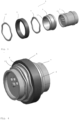
- Fig. 3 shows a three-dimensional schematic representation of the mover 4 in an exploded view, comprising the cylinder 7 with the second groove 11, the yoke 6 with the first groove 9, the first wave retaining ring 8, the magnet ring 5 and the second wave retaining ring 10.
- Fig. 4 shows the mover 4 from Fig. 3 in an assembled state, whereby the axial waveform of the first wave retaining ring 8 and the second wave retaining ring 10 is clearly recognizable.
- Fig. 5 shows a schematic representation of the mover 4 of Fig. 3 in the assembled state in a side view and a sectional view through the plane AA, which is represented by a line.
Landscapes
- Engineering & Computer Science (AREA)
- Mechanical Engineering (AREA)
- General Engineering & Computer Science (AREA)
- Reciprocating, Oscillating Or Vibrating Motors (AREA)
Abstract
The invention relates to a linear compressor (1) with a linear electric motor comprising a stator (2) with a coil (3) and a mover (4), wherein the mover (4) has a magnet ring (5) made of a permanent magnet, a yoke (6) for distributing the magnetic field and a cylinder (7), wherein a first wave retaining ring (8) is arranged in a first circular groove (9) in the yoke (6) next to the magnet ring (5).
Description
- The present invention relates to a linear compressor with a linear electric motor comprising a stator with a coil and a mover, in particular for a household appliance.
- Several linear compressors with linear electric motors are known from the prior art.
-
US8876497B2 discloses a linear compressor comprising a cylinder having a compression space for refrigerant therein, a piston that reciprocates linearly within the cylinder in an axial direction to compress the refrigerant, and a frame having a mounting hole so that one end of the cylinder can be mounted thereon and a deformation preventing portion in a portion around the mounting hole that is brought into contact with the one end of the cylinder. Even if the size of the cylinder is increased and the size of the frame is limited, the frame obtains sufficient strength to support the cylinder, thereby reducing mounting deformations and improving operational reliability. - One disadvantage of this linear compressor is that the linear compressor is subject to strong temperature changes due to the compression of the coolant, which can damage the moving parts of the linear compressor. This can shorten the service life of the linear compressor.
- The problem of the present invention is therefore to provide a linear compressor with a linear electric motor which ensures reliable operation even in the event of severe temperature changes.
- The invention relates to a linear compressor with a linear electric motor comprising a stator with a coil and a mover, wherein the mover has a magnet ring made of a permanent magnet, a yoke for distributing the magnetic field and a cylinder, wherein a first wave retaining ring is arranged in a first circular groove in the yoke next to the magnet ring.
- The cylinder of the linear compressor can move along a linear path to minimize friction and reduce energy loss during motion conversion compared to conventional compressors. This technology has been successfully used in cryogenic applications, which can be oil-free. The linear compressor with valve therefore enables the use of compact heat exchangers. The linear compressor can be connected to alternating current, for example by means of a diode. The cylinder can be spring-loaded and moved relative to a fixed piston by means of the mover, which is driven by the linear electric motor. During a positive cycle of the alternating current, the diode allows current to flow through the stator's electromagnet and creates a magnetic field which acts on the mover and consequently moves the cylinder backwards away from the piston, compressing the spring and consequently creating suction so that the gas medium or coolant is drawn into a compression chamber. During a negative cycle of the alternating current, the diode can block the current flow to the stator's electromagnet, which relaxes the spring, moves the piston forward and compresses the refrigerant. The compressed refrigerant can then be discharged via a valve to achieve the desired cooling effect.
- The linear compressor can be used for example for refrigerators.
- The linear electric motor can have a stator in the form of a cylindrical coil with further stator segments and the mover inside the stator.
- The yoke is suitable for distributing the magnetic field so that the driving force of the linear electric motor is amplified.
- The elastic properties of the first wave retaining ring in the first circular groove in the yoke next to the magnet ring make it possible to cushion the compressive forces and compensate for the expansion and contraction of the components of the mover caused by temperature changes.
- Advantageously, a second wave retaining ring can additionally be arranged in a second circular groove on an outer surface of the cylinder next to a first side of the annular yoke.
- The second wave retaining ring in the second circular groove additionally compensates for the expansions and contractions of the mover's components caused by temperature changes using the elastic properties of the second wave retaining ring.
- Advantageously, the mover comprising the magnet ring, the yoke and the cylinder can be shaped with circular symmetry relative to an axis of symmetry of the mover.
- The circularly symmetrical design relative to the axis of symmetry of the component of the mover ensures an even distribution of the frictional forces that occur.
- Advantageously, the magnet ring, the yoke and the cylinder can be made of different materials with different coefficients of thermal expansion.
- The magnet ring can be made of any permanent magnet, whereby the cylinder can be made of steel. By choosing different materials with different coefficients of thermal expansion, correspondingly higher expansions and contractions of the components of the mover are caused by temperature changes.
- Advantageously, the first wave retaining ring and/or the second wave retaining ring can be shaped and designed with respect to elasticity in such a way that expansion and/or contraction of the components of the mover, namely the magnet ring, the yoke and the cylinder, in a direction parallel to the axis of symmetry of the mover, which are caused by temperature changes and/or by different materials with different coefficients of thermal expansion, are compensated.
- As a result, the expansions and contractions that occur are reliably compensated for by the arrangement of the first wave retaining ring and/or the second wave retaining ring.
- Advantageously, the first wave retaining ring may be arranged and shaped to exert a compressive force on a wall of the first groove on a first side of the magnet ring upon movement of the mover in one direction or to exert a compressive force on the magnet ring upon movement of the mover in an opposite direction while transmitting a reaction force to a shoulder of the yoke on an opposite second side of the magnet ring.
- As a result, forces occurring during the movement of the mover are slightly cushioned by the elastic effect of the first wave retaining ring, preventing possible damage to the mover.
- Advantageously, the second wave retaining ring may be arranged and shaped to exert a compressive force on a wall of the second groove on a first side of the yoke upon movement of the mover in one direction or to exert a compressive force on the yoke upon movement of the mover in an opposite direction, whereby a reaction force is transmitted to a shoulder of the cylinder on an opposite second side of the yoke.
- As a result, forces occurring during the movement of the mover are easily absorbed by the elastic effect of the additional second wave retaining ring, preventing possible damage to the mover.
- Advantageously, the mover can be designed in such a way that radial expansions or contractions of the mover components, namely the magnet ring, the yoke and the cylinder, caused by temperature changes are compensated for by radial gaps between the mover components.
- The radial gaps are therefore dimensioned in such a way that the radial expansions and contractions of the components are compensated for by temperature changes.
- Advantageously, a piston can be arranged inside the cylinder, whereby the oscillating movement of the cylinder relative to the stationary piston compresses a gas medium or a coolant in a chamber between the piston and the cylinder and then the compressed gas medium or coolant is drained through an outlet valve in order to achieve the desired cooling effect.
- This achieves the desired cooling effect by draining the compressed coolant via the outlet valve.
- The invention is explained with reference to the following drawings:
- Fig. 1
- a schematic representation of a linear compressor with a linear electric motor;
- Fig. 2
- an enlarged view of an area from
Fig. 1 ; - Fig. 3
- a three-dimensional schematic representation of the mover in an exploded view;
- Fig. 4
- a three-dimensional schematic representation of the mover 4 from
Fig. 3 in an assembled state; - Fig. 5
- a schematic representation of the mover from
Fig. 3 in the assembled state in a side view and a sectional view. -
Fig. 1 shows a schematic representation of a linear compressor 1 with a linear electric motor comprising a stator 2 with acoil 3 and a mover 4, the mover 4 having amagnet ring 5 made of a permanent magnet, ayoke 6 for distributing the magnetic field and acylinder 7, wherein a firstwave retaining ring 8 with an axial waveform is arranged in a firstcircular groove 9 in theyoke 6 next to themagnet ring 5 and a secondwave retaining ring 10 with an axial waveform is arranged in a secondcircular groove 11 on an outer surface of thecylinder 7. Apiston 12 is arranged inside thecylinder 7, whereby a gas medium or a coolant is compressed in achamber 13 between thepiston 12 and thecylinder 7 by the oscillating movement of thecylinder 7 relative to thestationary piston 12. The circledarea 14 is shown enlarged inFig. 2 . The components of the mover 4, namely themagnet ring 5, theyoke 6 and thecylinder 7, are circularly symmetrical relative to an axis ofsymmetry 15 of the mover 4. -
Fig. 2 shows an enlarged view of the circledarea 14 ofFig. 1 . The firstwave retaining ring 8 is arranged and shaped to exert a compressive force on awall 20 of thefirst groove 9 on afirst side 21 of themagnet ring 5 upon movement of the mover 4 in a first direction, or to exert a compressive force on themagnet ring 5 upon movement of the mover 4 in an opposite second direction, while transmitting a reaction force to ashoulder 22 of theyoke 6 on an oppositesecond side 23 of themagnet ring 5. The secondwave retaining ring 10 is arranged and shaped to exert a compressive force on awall 24 of thesecond groove 11 on afirst side 25 of theyoke 6 upon movement of the mover 4 in one direction or to exert a compressive force on theyoke 6 upon movement of the mover 4 in an opposite direction, wherein a reaction force is transmitted to ashoulder 26 of thecylinder 7 on an oppositesecond side 27 of theyoke 6. Afirst gap 28 between thecylinder 7 and theyoke 6 and a second gap 29 between theyoke 6 and themagnet ring 5 are designed such that radial expansions or contractions of the components of the mover caused by temperature changes are compensated. -
Fig. 3 shows a three-dimensional schematic representation of the mover 4 in an exploded view, comprising thecylinder 7 with thesecond groove 11, theyoke 6 with thefirst groove 9, the firstwave retaining ring 8, themagnet ring 5 and the secondwave retaining ring 10. -
Fig. 4 shows the mover 4 fromFig. 3 in an assembled state, whereby the axial waveform of the firstwave retaining ring 8 and the secondwave retaining ring 10 is clearly recognizable. -
Fig. 5 shows a schematic representation of the mover 4 ofFig. 3 in the assembled state in a side view and a sectional view through the plane AA, which is represented by a line. -
- 1
- linear compressor
- 2
- stator
- 3
- coil
- 4
- mover
- 5
- magnet ring
- 6
- yoke
- 7
- cylinder
- 8
- first wave retaining ring
- 9
- first groove
- 10
- second wave retaining ring
- 11
- second groove
- 12
- piston
- 13
- chamber
- 14
- circled area
- 15
- axis of symmetry
- 20
- wall of the first groove
- 21
- first side of the magnet ring
- 22
- shoulder of the yoke
- 23
- second side of the magnet ring
- 24
- wall of the second groove
- 25
- first side of the yoke
- 26
- shoulder of the cylinder
- 27
- second side of the yoke
- 28
- first gap
- 29
- second gap
Claims (9)
- Linear compressor (1) with a linear electric motor comprising a stator (2) with a coil (3) and a mover (4), wherein the mover (4) has a magnet ring (5) made of a permanent magnet, a yoke (6) for distributing the magnetic field and a cylinder (7), wherein a first wave retaining ring (8) is arranged in a first circular groove (9) in the yoke (6) next to the magnet ring (5).
- Linear compressor (1) according to claim 1, wherein a second wave retaining ring (10) is additionally arranged in a second circular groove (11) on an outer surface of the cylinder (7) next to a first side (25) of the annular yoke (6).
- Linear compressor (1) according to claim 1 or 2, wherein the mover (4) comprising the magnet ring (5), the yoke (6) and the cylinder (7) is shaped with circular symmetry relative to an axis of symmetry (15) of the mover (4).
- The linear compressor (1) according to any one of claims 1-3, wherein the magnet ring (5), the yoke (6) and the cylinder (7) are made of different materials with different coefficients of thermal expansion.
- The linear compressor (1) according to any one of claims 1-4, wherein the first wave retaining ring (8) and/or the second wave retaining ring (10) are shaped and designed with respect to elasticity such that expansion and/or contraction of the components of the mover (4), namely the magnet ring (5), the yoke (6) and the cylinder (7), in a direction parallel to the axis of symmetry (15) of the mover (4), which are caused by temperature changes and/or by different materials with different coefficients of thermal expansion, are compensated.
- The linear compressor (1) according to any one of claims 1-5, wherein the first wave retaining ring (8) is arranged and shaped to exert a compressive force on a wall (20) of the first groove (9) on a first side (21) of the magnet ring (5) upon movement of the mover (4) in a first direction or to exert a compressive force on the magnet ring (5) upon movement of the mover (4) in an opposite direction, wherein a reaction force is transmitted to a shoulder (22) of the yoke (6) on an opposite second side (23) of the magnet ring (5).
- The linear compressor (1) according to any one of claims 1-6, wherein the second wave retaining ring (10) is arranged and shaped to exert a compressive force on a wall (24) of the second groove (11) on a first side (25) of the yoke (6) upon movement of the mover (4) in one direction or to exert a compressive force on the yoke (6) upon movement of the mover (4) in an opposite direction, wherein a reaction force is transmitted to a shoulder (26) of the cylinder (7) on an opposite second side (27) of the yoke (6).
- Linear compressor (1) according to any one of claims 1-7, wherein the mover (4) is designed such that radial expansions or contractions of the components of the mover (4), namely the magnet ring (5), the yoke (6) and the cylinder (7), caused by temperature changes are compensated by radial gaps (28, 29) between the components of the mover (4).
- Linear compressor (1) according to any one of claims 1-8, wherein a piston (12) is arranged within the cylinder (7), wherein a gas medium or a coolant is compressed by the oscillating movement of the cylinder (7) relative to the stationary piston (12) in a chamber (13) between the piston (12) and the cylinder (7) and subsequently the compressed gas medium or coolant is discharged through an outlet valve in order to achieve the desired cooling effect.
Priority Applications (4)
| Application Number | Priority Date | Filing Date | Title |
|---|---|---|---|
| EP23216496.2A EP4571108A1 (en) | 2023-12-14 | 2023-12-14 | Linear compressor with a linear electric motor |
| DE102024114992.2A DE102024114992A1 (en) | 2023-12-14 | 2024-05-28 | Linear compressor |
| PCT/EP2024/082832 WO2025124852A1 (en) | 2023-12-14 | 2024-11-19 | Linear compressor |
| PCT/EP2024/085763 WO2025125369A1 (en) | 2023-12-14 | 2024-12-11 | Linear compressor with a linear electric motor |
Applications Claiming Priority (1)
| Application Number | Priority Date | Filing Date | Title |
|---|---|---|---|
| EP23216496.2A EP4571108A1 (en) | 2023-12-14 | 2023-12-14 | Linear compressor with a linear electric motor |
Publications (1)
| Publication Number | Publication Date |
|---|---|
| EP4571108A1 true EP4571108A1 (en) | 2025-06-18 |
Family
ID=89222706
Family Applications (1)
| Application Number | Title | Priority Date | Filing Date |
|---|---|---|---|
| EP23216496.2A Pending EP4571108A1 (en) | 2023-12-14 | 2023-12-14 | Linear compressor with a linear electric motor |
Country Status (2)
| Country | Link |
|---|---|
| EP (1) | EP4571108A1 (en) |
| WO (1) | WO2025125369A1 (en) |
Citations (6)
| Publication number | Priority date | Publication date | Assignee | Title |
|---|---|---|---|---|
| US4632645A (en) * | 1984-11-22 | 1986-12-30 | Sawafuji Electric Co., Ltd. | Vibrating compressor |
| US7078832B2 (en) * | 2002-10-16 | 2006-07-18 | Matsushita Refrigeration Company | Linear motor, and linear compressor using the same |
| US20060250032A1 (en) * | 2005-05-06 | 2006-11-09 | Lg Electronics Inc. | Linear compressor |
| KR20090105469A (en) * | 2008-04-02 | 2009-10-07 | 엘지전자 주식회사 | Reciprocating compressor |
| US8876497B2 (en) | 2007-10-24 | 2014-11-04 | Lg Electronics Inc. | Linear compressor |
| US9488165B2 (en) * | 2010-03-15 | 2016-11-08 | Lg Electroncs Inc. | Reciprocating compressor |
-
2023
- 2023-12-14 EP EP23216496.2A patent/EP4571108A1/en active Pending
-
2024
- 2024-12-11 WO PCT/EP2024/085763 patent/WO2025125369A1/en active Pending
Patent Citations (6)
| Publication number | Priority date | Publication date | Assignee | Title |
|---|---|---|---|---|
| US4632645A (en) * | 1984-11-22 | 1986-12-30 | Sawafuji Electric Co., Ltd. | Vibrating compressor |
| US7078832B2 (en) * | 2002-10-16 | 2006-07-18 | Matsushita Refrigeration Company | Linear motor, and linear compressor using the same |
| US20060250032A1 (en) * | 2005-05-06 | 2006-11-09 | Lg Electronics Inc. | Linear compressor |
| US8876497B2 (en) | 2007-10-24 | 2014-11-04 | Lg Electronics Inc. | Linear compressor |
| KR20090105469A (en) * | 2008-04-02 | 2009-10-07 | 엘지전자 주식회사 | Reciprocating compressor |
| US9488165B2 (en) * | 2010-03-15 | 2016-11-08 | Lg Electroncs Inc. | Reciprocating compressor |
Also Published As
| Publication number | Publication date |
|---|---|
| WO2025125369A1 (en) | 2025-06-19 |
Similar Documents
| Publication | Publication Date | Title |
|---|---|---|
| US5772410A (en) | Linear compressor with compact motor | |
| JP3844359B2 (en) | Device for guiding and centering machine elements | |
| KR102178072B1 (en) | Linear compressor | |
| US7124678B2 (en) | Apparatus for preventing abrasion in reciprocal compressor | |
| US3991585A (en) | Cold-gas refrigerator | |
| US6565332B2 (en) | Linear compressor | |
| CN103122837B (en) | Adopt the Linearkompressor of three kinds of spring common support | |
| KR101766242B1 (en) | Receprocating compressor | |
| EP2402607B1 (en) | Long life seal and alignment system for small cryocoolers | |
| EP2818711B1 (en) | Linear compressor | |
| WO1998001661A1 (en) | Combination gas and flexure spring construction for free piston devices | |
| Unger | Linear compressors for clean and specialty gases | |
| CN104632578B (en) | The piston positioning means of Linearkompressor | |
| JP2008215440A (en) | Plate spring and refrigerator | |
| CN103352825A (en) | Linear compressor | |
| CN213627896U (en) | Linear compressor and linear Stirling refrigerator | |
| CN104806471A (en) | Opposed gas bearing linear compressor | |
| WO2025125369A1 (en) | Linear compressor with a linear electric motor | |
| US20170370354A1 (en) | Reciprocating motor and reciprocating compressor having a reciprocating motor | |
| EP4685349A1 (en) | Linear compressor with a linear electric motor and household appliance | |
| KR101981098B1 (en) | Linear compressor | |
| US7061145B2 (en) | Apparatus for fixing stator of reciprocating compressor | |
| CN119412315A (en) | A linear compressor with electromagnetic spring | |
| JP2003148341A (en) | Lead wire fitting structure of linear motor type driving part | |
| KR102399507B1 (en) | Motor and compressor including thereof |
Legal Events
| Date | Code | Title | Description |
|---|---|---|---|
| PUAI | Public reference made under article 153(3) epc to a published international application that has entered the european phase |
Free format text: ORIGINAL CODE: 0009012 |
|
| STAA | Information on the status of an ep patent application or granted ep patent |
Free format text: STATUS: THE APPLICATION HAS BEEN PUBLISHED |
|
| AK | Designated contracting states |
Kind code of ref document: A1 Designated state(s): AL AT BE BG CH CY CZ DE DK EE ES FI FR GB GR HR HU IE IS IT LI LT LU LV MC ME MK MT NL NO PL PT RO RS SE SI SK SM TR |
|
| STAA | Information on the status of an ep patent application or granted ep patent |
Free format text: STATUS: REQUEST FOR EXAMINATION WAS MADE |
|
| 17P | Request for examination filed |
Effective date: 20251218 |