EP4571104A1 - Rotor turn drive for wind turbine generator and method thereof - Google Patents
Rotor turn drive for wind turbine generator and method thereof Download PDFInfo
- Publication number
- EP4571104A1 EP4571104A1 EP24150458.8A EP24150458A EP4571104A1 EP 4571104 A1 EP4571104 A1 EP 4571104A1 EP 24150458 A EP24150458 A EP 24150458A EP 4571104 A1 EP4571104 A1 EP 4571104A1
- Authority
- EP
- European Patent Office
- Prior art keywords
- sprocket
- rtd
- shaft
- bracket
- chain
- Prior art date
- Legal status (The legal status is an assumption and is not a legal conclusion. Google has not performed a legal analysis and makes no representation as to the accuracy of the status listed.)
- Pending
Links
Images






Classifications
-
- F—MECHANICAL ENGINEERING; LIGHTING; HEATING; WEAPONS; BLASTING
- F03—MACHINES OR ENGINES FOR LIQUIDS; WIND, SPRING, OR WEIGHT MOTORS; PRODUCING MECHANICAL POWER OR A REACTIVE PROPULSIVE THRUST, NOT OTHERWISE PROVIDED FOR
- F03D—WIND MOTORS
- F03D80/00—Details, components or accessories not provided for in groups F03D1/00 - F03D17/00
- F03D80/50—Maintenance or repair
-
- F—MECHANICAL ENGINEERING; LIGHTING; HEATING; WEAPONS; BLASTING
- F03—MACHINES OR ENGINES FOR LIQUIDS; WIND, SPRING, OR WEIGHT MOTORS; PRODUCING MECHANICAL POWER OR A REACTIVE PROPULSIVE THRUST, NOT OTHERWISE PROVIDED FOR
- F03D—WIND MOTORS
- F03D15/00—Transmission of mechanical power
-
- F—MECHANICAL ENGINEERING; LIGHTING; HEATING; WEAPONS; BLASTING
- F05—INDEXING SCHEMES RELATING TO ENGINES OR PUMPS IN VARIOUS SUBCLASSES OF CLASSES F01-F04
- F05B—INDEXING SCHEME RELATING TO WIND, SPRING, WEIGHT, INERTIA OR LIKE MOTORS, TO MACHINES OR ENGINES FOR LIQUIDS COVERED BY SUBCLASSES F03B, F03D AND F03G
- F05B2260/00—Function
- F05B2260/40—Transmission of power
- F05B2260/402—Transmission of power through friction drives
- F05B2260/4022—Transmission of power through friction drives through endless chains
-
- Y—GENERAL TAGGING OF NEW TECHNOLOGICAL DEVELOPMENTS; GENERAL TAGGING OF CROSS-SECTIONAL TECHNOLOGIES SPANNING OVER SEVERAL SECTIONS OF THE IPC; TECHNICAL SUBJECTS COVERED BY FORMER USPC CROSS-REFERENCE ART COLLECTIONS [XRACs] AND DIGESTS
- Y02—TECHNOLOGIES OR APPLICATIONS FOR MITIGATION OR ADAPTATION AGAINST CLIMATE CHANGE
- Y02E—REDUCTION OF GREENHOUSE GAS [GHG] EMISSIONS, RELATED TO ENERGY GENERATION, TRANSMISSION OR DISTRIBUTION
- Y02E10/00—Energy generation through renewable energy sources
- Y02E10/70—Wind energy
- Y02E10/72—Wind turbines with rotation axis in wind direction
Definitions
- the present invention is in the field of wind turbine.
- the present invention provides a rotor turn drive for service intervention operation of wind turbine generator.
- the rotor turn drive will help in the rotation of the rotor to position the blade and lock the Rotor, during service and maintenance process.
- the wind has historically been one of the most widely used natural resources to provide the energy necessary to power our needs. As the demand for energy has increased and the supplies of fossil dwindled, resulting there has been a renewed look by electrical utility companies at alternative methods for producing electrical power.
- One method of electrical production involves the harnessing of the wind by a wind turbine to drive an electrical generator.
- Rotor turn Drive is used for service intervention operation.
- service intervention in the wind turbine it is required to move the rotor into a defined position.
- the external auxiliary drive is usually used by the technician to do so, however, at high speed, it becomes difficult. It is still not possible to position the blade and lock the Rotor, efficiently, during service and maintenance intervention.
- ES2410104T3 discloses an auxiliary drive system for driving a wind turbine component, comprising a motor (200), reduction gears (100) comprising multiple stages operatively connected to said engine, and a pinion operatively connected to said reducing gears to drive said wind turbine component, the auxiliary drive system being also provided with one or more locks (300, 400, 500; 600; 700), said one or more locks comprising at least one blocking element (350; 540, 560; 640, 660; 750).
- ES2661265T3 discloses a maintenance system (30) for maintaining a brake device (24) of a yaw braking system of a wind turbine comprising the brake device (24) and a brake disc (22) arranged horizontally, wherein the system includes a frame (32), characterized in that the maintenance system (30) comprises: - mounting means (34) for mounting the frame (32) in a fixed position with respect to the brake disc (22 ), - coupling means (36) for securing at least a part (25; 26) of the brake device (24) to the frame (32), and - guiding means (38) that are adapted to allow said part ( 25; 26) of the brake device (24), while secured to the frame (32), move in the frame (32) with respect to the brake disc (22).
- the maintenance system (30) comprises: - mounting means (34) for mounting the frame (32) in a fixed position with respect to the brake disc (22 ), - coupling means (36) for securing at least a part (25; 26) of the brake device (24) to
- WO2002044561A1 discloses a wind power plant, comprising means for moving the rotor blades (RB) about the longitudinal axis (LA).
- Said means have at least one actuator (SA) with a control motor (SM) for moving at least one rotor blade (RB), at least one auxiliary generator (HG) for supplying electrical energy from the kinetic energy of the rotor shaft (RW), a fault detection device (SI) which is active in a fault scenario (FF), and a switching-over device (US).
- SA actuator
- SM control motor
- HG auxiliary generator
- FF fault detection device
- US switching-over device
- said switching-over device conducts the electrical energy of the auxiliary generator to at least one control motor, in order to move at least one rotor blade into a flag position (FS).
- FS flag position
- the primary objective of the present invention is to overcome the drawback associated with prior art.
- Another object of the present invention is to provide a rotor turn drive for service intervention operation of wind turbine generator.
- Another object of the present invention is to provide a cost effective rotor turn drive for service intervention operation of wind turbine generator.
- Another object of the present invention is to provide a rotor turn drive for service intervention operation of wind turbine generator which is easy to install and remove.
- Another object of the present invention is to provide a rotor turn drive for service intervention operation of wind turbine generator which is easy to install and remove.
- Another object of the present invention is to provide a rotor turn drive which can used manually without any risk issue and in absence of power supply.
- Another object of the present invention is to provide a method of operation of a rotor turn drive for service intervention operation of wind turbine generator.
- the invention provides a rotor turn drive for service intervention operation of wind turbine generator comprising:
- torque wrench socket (6) comprises a reversible rachet and a fixed square drive pin for tightening.
- the RTD bracket (1) is attached to a base having plurality of holes, wherein the holes having provision for bolt, wherein the bolt is inserted in the holes and tightened on the generator frame.
- the RTD bracket (1) comprises an idler mechanism configured to provide tension to the RTD chain (3).
- At least six bolt of size M12 is configured to attach the RTD bracket (1) with the generator frame, wherein the bolts having tensile area of 113 mm2 and stress on Bolts is 90MPA.
- the torque wrench socket (6) is configured to rotate manually or by an electric drive, wherein the ratio (1:5) of chain sprockets (2, 12) reduces the torque to 5:1, wherein torque required to rotate the shaft of the generator(13) is at least 780N-M and torque required to rotate torque wrench socket (6) is 126N-M .
- RTD bracket (1) comprises a braking mechanism installed such that it restricts movement of shaft generator by intervening the inside the RTD chain (3).
- the invention provides a method of operation of rotor turn drive for service intervention operation of wind turbine generator, comprising steps of:
- present invention provides a rotor turn drive for service intervention operation of wind turbine generator.
- the invention provides a rotor turn drive for service intervention operation of wind turbine generator comprising:
- torque required to rotate the shaft of the generator (13) is 780N-M while the torque required to rotate torque wrench socket (6) is 156N-M.
- 360 degree rotation of coupling shaft will rotate main rotor shaft to 2.3 degree, with 1:155 Gear ratio.
- the distance between wire cut sprocket or split sprocket is approx. 1000nm.
- the torque wrench socket (6) comprises a reversible rachet and fixed square drive pin for tightening.
- the RTD bracket (1) is attached to a base comprising plurality of holes, wherein the holes comprises provision for bolt, said bolt is inserted in the holes and tightened on the generator frame.
- the RTD bracket (1) comprises an idler mechanism configured to provide tension to the RTD chain (3).
- At least six bolt of size M12 is configured to attach the RTD bracket (1) with the generator frame / bracket, said bolts comprises tensile area of 113 mm2 and stress on Bolts is 90MPA.
- RTD bracket (1) comprises a braking mechanism installed such that it restrict movement of shaft generator by intervening the inside the RTD chain (3).
- RTD bracket (1) comprises a braking mechanism installed such that it restrict movement of shaft generator by intervening the inside the RTD chain (3).
- the small sprocket is rotated through electric torque runner or ratchet wrench which will rotate HSS shaft through split sprocket while the HSS Shaft of Gearbox in turn will rotate the LSS and Rotor hub ensuring the rotation of the Rotor Hub in slow speed enabling to lock the Rotor manually.
- the wire cut sprocket (2) being connected to said small sprocket which is mounted in the bracket through a chain, is mounted to coupling which in turn is connected to Gearbox HSS.
- the rotor turn drive mechanism can be rotated manually as well as with Service Variant Turn drive.
- the newly developed mechanism is designed to support for Rotor locking during following operations Service Interventions which make this cost effective as we use this portable tool.
- the mechanism and process followed to the service intervention is very simple.
- the rotor turn drive of the present invention is used for the service intervention operation of wind turbine generator.
- the RTD bracket is mounted on the frame of the wind power generator.
- the bearing and sprocket is mounted on the bracket.
- the torque moment and loads which is connected to wire cut sprocket though chain.
- a torque wrench or electric runner is used to rotate the shaft mounted with RTD Bracket with bearing and sprocket which in turn rotates the split sprocket and thereby moving the shaft of the generator.
- the RTD bracket (1) as shown in Figure 2 comprises plurality of bearing and the sprocket.
- the sprocket has plurality of teeth around its circumference and the sprocket is attached to the shaft.
- the RTD chain (3) is mesh with the sprocket and the wire cut sprocket (2) teeth for providing the rotation to the shaft.
- the RTD bracket (1) is attached to a base having plurality of holes, wherein the holes have provision for bolt, wherein the bolt is inserted in the holes and tightened on the generator frame.
- For tightening RTD bracket (1) at least six bolt of size M12 is used to attach the RTD bracket (1) with the generator frame.
- the RTD bracket (1) is attached to the generator frame.
- the base of the RTD bracket has plurality of holes.
- the said the holes have provision for bolt, the bolt is inserted in the holes and tightened on the generator frame.
- the bolt used for tightening is hex type with size of M12 is used to attach the RTD bracket (1) with the generator frame.
- the RTD bracket (1) includes bearing unit, shaft and sprocket.
- the bearing unit is attached to the RTD bracket in hole provided thereon and tightened by the nut and bolts.
- the RTD bracket has two parallel sides where the hole for the bearing unit is provided at each side.
- the shaft is inserted into the hole of the RTD bracket before attaching the bearing unit.
- the shaft bears the sprocket in the middle of its length and tightened along the cut made on the shaft for the tight attachment.
- the RTD bracket (1) includes bearing unit, shaft (9) and sprocket (12).
- the bearing unit, shaft (9) and sprocket (12) can be adjustable.
- the shaft (9) has cut along its length which is provided for the tightening of the sprocket (12) of the shaft (9).
- the cut along the length of the shaft provides more space for the alignment of the sprocket (12) with the wire cut sprocket (12).
- the alignment of the sprocket is essential to RTD chain tension and for the proper torque management.
- the wire cut sprocket (2) has circular shape.
- the wire cut sprocket (2) is assembled by joining two semi-circle halves around shaft of wind turbine generator.
- the wire cut sprocket (2) includes plurality of teeth around its circumference. The said teeth provides the wire cut sprocket (2) grip around the shaft of wind turbine generator.
- the two halves of the wire cut sprocket (2) provides the technician option of assemble the wire cut sprocket (2) around the shaft of the wind turbine generator with ease. The assembly time is less time consuming as two halves need to be attached together with nut and bolt, can be easily assembled by the less skilled technician.
- the RTD chain (3) as shown in Figure 5 , which is meshed to the sprocket (12) of RTD bracket (1) and further meshed with the wire cut sprocket (2). While connecting the respective sprocket of the rotor turn drive by the RTD chain (3), first the RTD chain (3) is mesh with the teeth of the sprocket (12) and in next step the RTD chain (3) is mesh with the teeth of the wire cut sprocket (2). Next step is to check alignment of the RTD chain (3) with the sprocket, thereafter once the alignment meets the working requirement, then the RTD chain (3) is connected around its length by a connecting mechanism (31). After attachment of RTD chain (3) with the connecting mechanism (31), the RTD chain (3) forms loop structure and is now configured to rotate both of the sprocket when the torque is applied by rotating torque wrench socket (6).
- FIG. 6 to7 shows the working of rotor turn drive of the present invention for the service intervention operation of wind turbine generator.
- the RTD bracket (1) is mounted on the frame of the wind power generator.
- the bearing (10) and sprocket (12) is mounted on the RTD bracket (1).
- RTD chain (3) is connected with the sprocket (12) and the wire cut sprocket (2).
- the alignment of the RTD chain (3) is checked and is connected around its length by a connecting mechanism (31).
- the RTD chain (3) forms loop structure and is now configured to rotate both sprockets when the torque is applied by rotating torque wrench socket (6).
- the torque moment to the loads can be provided electrically or manually.
- Figure 6 shows the manual working of rotor turn drive of the present invention.
- a torque tool is attached to the torque wrench socket (6) and torque tool is rotated by the technician by their hand.
- the rotation of torque tool creates torque for the rotation of both the sprockets (12, 2).
- the movement of sprockets through the RTD chain (3) further rotates the shaft of the generator of the wind turbine.
- the shaft movement of the wind turbine generator provided movement to the blade of wind turbine.
- the electric torque tool (21) is attached to the torque wrench socket (6) and torque tool is rotated is powered by the portable battery attached thereon.
- the rotation of torque tool creates torque for the rotation of both the sprockets (12, 2).
- the movement of sprockets through the RTD chain (3) further rotates the shaft of the generator of the wind turbine.
- the shaft movement of the wind turbine generator provided movement to the blade of wind turbine.
- Figure 8 shows the sprockets (2, 12) of the present invention.
- the sprockets (2, 12) have the size ratio of 1:5.
- the said ratio provides the added advantage of force required to rotate the smaller sprocket (12) by a technician for service intervention is less.
- the space inherently available near wind turbine generator for any maintenance work is very limited.
- the present invention system can be easily assembled in the said space by the technician in less time. Further, after installation of the system the main required work is to rotate the shaft (13) of the wind turbine generator to start the maintenance work. Usually, a hand lever or wrench is carried by the technicians to rotate the wrench socket (6).
- the ratio of the sprockets allows the rotor system to reduce the force required for rotation of the wrench socket (6).
- the sprockets (2, 12) with the size ratio of 1:5 reduces the force requirement, example: the force required to rotate the rotor (13) of the wind turbine generator is at least 780 N-M and due to the size ratio is 1:5 the force require to rotate the sprocket (12) is 156N-M. the required force is easily manageable by the technician. Further, anyhow technician is not fit to rotate the wrench socket (6) manually, then small battery-operated electric drive can fulfil the purpose in the available space.
- rotor turn drive provide the required movement to the blade of the wind turbine.
- a braking mechanism (11) is activated.
- the braking mechanism (11) is installed in such a way that it restrict movement of shaft of the generator by intervening the inside the RTD chain (3).
- the braking mechanism (11) provides extra cushion and safety to the technical to restrict the further movement and prevent any accident during the maintenance of the wind turbine generator.
- the following steps are to be performed for operating the rotor turn drive to rotate the rotor to position the blade and lock the Rotor, during service and maintenance process.
Landscapes
- Engineering & Computer Science (AREA)
- Life Sciences & Earth Sciences (AREA)
- Sustainable Development (AREA)
- Sustainable Energy (AREA)
- Chemical & Material Sciences (AREA)
- Combustion & Propulsion (AREA)
- Mechanical Engineering (AREA)
- General Engineering & Computer Science (AREA)
- Wind Motors (AREA)
Abstract
Description
- The present invention is in the field of wind turbine. Particularly, the present invention provides a rotor turn drive for service intervention operation of wind turbine generator. The rotor turn drive will help in the rotation of the rotor to position the blade and lock the Rotor, during service and maintenance process.
- The following background discussion includes information that may be useful in understanding the present invention. It is not an admission that any of the information provided herein is prior art or relevant to the presently claimed invention, or that any publication expressly or implicitly referenced is prior art.
- The wind has historically been one of the most widely used natural resources to provide the energy necessary to power our needs. As the demand for energy has increased and the supplies of fossil dwindled, resulting there has been a renewed look by electrical utility companies at alternative methods for producing electrical power. One method of electrical production involves the harnessing of the wind by a wind turbine to drive an electrical generator.
- As wind turbine is a continuously moving machine, hence, it is difficult to service and maintain the turbine, during its motion. Thus, in wind turbine generator, Rotor turn Drive is used for service intervention operation. During service intervention in the wind turbine, it is required to move the rotor into a defined position. At low speeds, the external auxiliary drive is usually used by the technician to do so, however, at high speed, it becomes difficult. It is still not possible to position the blade and lock the Rotor, efficiently, during service and maintenance intervention.
-
ES2410104T3 - Further,
ES2661265T3 - Another document,
WO2002044561A1 discloses a wind power plant, comprising means for moving the rotor blades (RB) about the longitudinal axis (LA). Said means have at least one actuator (SA) with a control motor (SM) for moving at least one rotor blade (RB), at least one auxiliary generator (HG) for supplying electrical energy from the kinetic energy of the rotor shaft (RW), a fault detection device (SI) which is active in a fault scenario (FF), and a switching-over device (US). When activated, said switching-over device conducts the electrical energy of the auxiliary generator to at least one control motor, in order to move at least one rotor blade into a flag position (FS). Associated with this is the advantage that low-wear, low-maintenance control motors can be used without a static auxiliary energy device. - The above-mentioned technologies are very complicated in functioning as well as are expensive. Also, it is still not possible for the rotor turn drive to lock at different locking position during service intervention operation in a simple and cost-effective manner. Hence, there is a need of a rotor turn drive mechanism, which can be rotated manually as well as with Service Variant Turn drive and which can provide support for Rotor locking during Service Intervention.
- Further, there is also a need of a rotor turn drive mechanism which is a service portable tool and is not an inherent part of the turbine, thus, reducing the overall cost and budget of the wind turbine.
- The primary objective of the present invention is to overcome the drawback associated with prior art.
- Another object of the present invention is to provide a rotor turn drive for service intervention operation of wind turbine generator.
- Another object of the present invention is to provide a cost effective rotor turn drive for service intervention operation of wind turbine generator.
- Another object of the present invention is to provide a rotor turn drive for service intervention operation of wind turbine generator which is easy to install and remove.
- Another object of the present invention is to provide a rotor turn drive for service intervention operation of wind turbine generator which is easy to install and remove.
- Another object of the present invention is to provide a rotor turn drive which can used manually without any risk issue and in absence of power supply.
- Another object of the present invention is to provide a method of operation of a rotor turn drive for service intervention operation of wind turbine generator.
- In an aspect, the invention provides a rotor turn drive for service intervention operation of wind turbine generator comprising:
- a) a RTD bracket (1) attached to the wind turbine generator at 6-degree inclination comprises plurality of bearings a sprocket (12) and a shaft (9), wherein the sprocket (12) having plurality of teeth around its circumference, wherein the sprocket is attached to the shaft (9);
- b) a wire cut sprocket (2) having circular shape, wherein the wire cut sprocket (2) assembled by joining two semi-circle halves around a shaft (13) of wind turbine generator comprises plurality of holes around its circumference, wherein when the wire cut sprocket (2) assembled around the shaft (13) of the generator the holes around the circumference the wire cut sprocket (2) matches with plurality of holes of shaft and coupled with plurality of bolts;
- c) a RTD chain (3), wherein the RTD chain (3) is configured to mesh with the sprocket (12) and the wire cut sprocket (2) teeth to form loop structure, wherein the wire cut sprocket (2) and the sprocket (12) having size ratio of 1:5; and
- d) a torque wrench socket (6), wherein the torque wrench socket is attached to the sprocket of the RTD bracket (1);
- In an embodiment, the wire cup sprocket (2) having weight of 5kg each with Z = 65, Pitch Diameter = 395 mm and Pitch = 19.05 mm.
- In an embodiment, the RTD chain (3) is made of stainless-steel having Pitch = 19.05 mm, Length = 3000 mm and Weight = 3.9 kg (1.3 kg/m).
- In an embodiment, torque wrench socket (6) comprises a reversible rachet and a fixed square drive pin for tightening.
- In an embodiment, the RTD bracket (1) is attached to a base having plurality of holes, wherein the holes having provision for bolt, wherein the bolt is inserted in the holes and tightened on the generator frame.
- In an embodiment, the RTD bracket (1) comprises an idler mechanism configured to provide tension to the RTD chain (3).
- In an embodiment, at least six bolt of size M12 is configured to attach the RTD bracket (1) with the generator frame, wherein the bolts having tensile area of 113 mm2 and stress on Bolts is 90MPA.
- In an embodiment, the torque wrench socket (6) is configured to rotate manually or by an electric drive, wherein the ratio (1:5) of chain sprockets (2, 12) reduces the torque to 5:1, wherein torque required to rotate the shaft of the generator(13) is at least 780N-M and torque required to rotate torque wrench socket (6) is 126N-M .
- In an embodiment, RTD bracket (1) comprises a braking mechanism installed such that it restricts movement of shaft generator by intervening the inside the RTD chain (3).
- In an aspect, the invention provides a method of operation of rotor turn drive for service intervention operation of wind turbine generator, comprising steps of:
- a) mounting a wire cut sprocket (2) on a shaft (13) of a wind turbine generator and coupling the wire cut sprocket (2) and the shaft (13) with plurality of bolts wherein the bolts are inserted into plurality of holes provided at circumference of the wire cut sprocket (2) and shaft (13);
- b) mounting the RTD bracket (1) on generator frame and connecting the sprocket and the wire cut sprocket (2) with RTD chain (3) by adding chain link;
- c) connecting hand lever to the sprocket (6) and checking the alignment of sprocket and RTD chain (3); and
- d) rotating the sprocket (6) which in turn rotates the sprocket (12) and the RTD chain (3), sprocket (2) and shaft (13), wherein the torque applied by rotating torque wrench socket (6), wherein the size ratio (1:5) of sprockets (2, 12) reduces torque to 5:1 and enables manual rotation of torque wrench socket (6).
- This together with the other aspects of the present invention along with the various features of novelty that characterized the present disclosure is pointed out with particularity in claims annexed hereto and forms a part of the present invention. For better understanding of the present disclosure, its operating advantages, and the specified objective attained by its uses, reference should be made to the accompanying descriptive matter in which there are illustrated exemplary embodiments of the present invention.
- The accompanying drawings, which are incorporated in and constitute a part of this disclosure, illustrate exemplary embodiments and, together with the description, explain the disclosed principles. The reference numbers are used throughout the figures to describe the features and components. Some embodiments of system and/or methods in accordance with embodiments of the present subject matter are now described, by way of example only, and regarding the accompanying figures, in which:
-
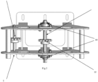
Figure 1 : illustrates the rotor turn drive of the present invention. -
Figure 2 : illustrates bracket of the rotor turn drive of the present invention. -
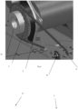
Figure 3 : illustrates bracket installation at generator in the present invention. -
Figure 4 : illustrates the rotor turn drive in working condition in the present invention. -
Figure 5 : illustrates the chain connection in the present invention. -
Figure 6 : illustrates the manual drive of rotor turn drive of the present invention. -
Figure 7 : illustrates the electric drive of rotor turn drive of the present invention. -
Figure 8 : illustrates the ratio conversion of force due to sprocket size ratio in present invention. -
Figure 9 : illustrates the assembly and coupling of wire cut sprocket with shaft of the generator. -
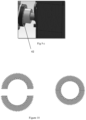
Figure 10 illustrates view of split sprocket or wire cut sprocket of the present invention -
Figure 11 illustrates another embodiment of rotor turn drive of the present invention -
Figure 12 illustrates another embodiment of rotor turn drive of the present invention - In the present document, the word "exemplary" is used herein to mean "serving as an example, instance, or illustration." Any embodiment or implementation of the present subject matter described herein as "exemplary" is not necessarily to be construed as preferred or advantageous over other embodiments.
- While the disclosure is susceptible to various modifications and alternative forms, specific embodiment thereof has been shown by way of example, in the drawings and will be described in detail below. It should be understood, however, that it is not intended to limit the disclosure to the specific forms disclosed, but on the contrary, the disclosure is to cover all modifications, equivalents, and alternative falling within the spirit and the scope of the disclosure.
- The terms "comprises", "comprising", "includes", or any other variations thereof, are intended to cover a non-exclusive inclusion, such that a setup, device or method that comprises a list of components or steps does not include only those components or steps but may include other components or steps not expressly listed or inherent to such setup or device or method. In other words, one or more elements in a system or apparatus proceeded by "comprises... a" does not, without more constraints, preclude the existence of other elements or additional elements in the system or method.
- In an embodiment, present invention provides a rotor turn drive for service intervention operation of wind turbine generator.
- In an aspect, the invention provides a rotor turn drive for service intervention operation of wind turbine generator comprising:
- a) a RTD bracket (1) attached to the wind turbine generator at 6-degree inclination comprises plurality of bearings a sprocket (12) and a shaft (9), wherein the sprocket (12) having plurality of teeth around its circumference, wherein the sprocket is attached to the shaft (9);
- b) a wire cut sprocket (2) having circular shape, wherein the wire cut sprocket (2) assembled by j oining two semi-circle halves around a shaft (13) of wind turbine generator comprises plurality of holes around its circumference, wherein when the wire cut sprocket (2) assembled around the shaft (13) of the generator the holes around the circumference the wire cut sprocket (2) matches with plurality of holes of shaft and coupled with plurality of bolts;
- c) a RTD chain (3), wherein the RTD chain (3) is configured to mesh with the sprocket (12) and the wire cut sprocket (2) teeth to form loop structure, wherein the wire cut sprocket (2) and the sprocket (12) having size ratio of 1:5; and
- d) a torque wrench socket (6), wherein the torque wrench socket is attached to the sprocket of the RTD bracket (1);
- In an embodiment, torque required to rotate the shaft of the generator (13) is 780N-M while the torque required to rotate torque wrench socket (6) is 156N-M.
- In an embodiment, 360 degree rotation of coupling shaft will rotate main rotor shaft to 2.3 degree, with 1:155 Gear ratio.
- In an embodiment, the wire cup sprocket (2) having weight of 5kg each with Z = 65, Pitch Diameter = 395 mm and Pitch = 19.05 mm.
- In an embodiment, the RTD chain (3) is made of stainless-steel having Pitch = 19.05 mm, Length = 3000 mm and Weight = 3.9 kg (1.3 kg/m).
- In an embodiment, the distance between wire cut sprocket or split sprocket is approx. 1000nm.
- In an embodiment, the torque wrench socket (6) comprises a reversible rachet and fixed square drive pin for tightening.
- In an embodiment, the RTD bracket (1) is attached to a base comprising plurality of holes, wherein the holes comprises provision for bolt, said bolt is inserted in the holes and tightened on the generator frame.
- In an embodiment, the RTD bracket (1) comprises an idler mechanism configured to provide tension to the RTD chain (3).
- In an embodiment, at least six bolt of size M12 is configured to attach the RTD bracket (1) with the generator frame / bracket, said bolts comprises tensile area of 113 mm2 and stress on Bolts is 90MPA.
- In an embodiment, RTD bracket (1) comprises a braking mechanism installed such that it restrict movement of shaft generator by intervening the inside the RTD chain (3).
- In an embodiment, RTD bracket (1) comprises a braking mechanism installed such that it restrict movement of shaft generator by intervening the inside the RTD chain (3).
- In an embodiment, the small sprocket is rotated through electric torque runner or ratchet wrench which will rotate HSS shaft through split sprocket while the HSS Shaft of Gearbox in turn will rotate the LSS and Rotor hub ensuring the rotation of the Rotor Hub in slow speed enabling to lock the Rotor manually.
- In an embodiment, the wire cut sprocket (2), being connected to said small sprocket which is mounted in the bracket through a chain, is mounted to coupling which in turn is connected to Gearbox HSS.
- Further, the rotor turn drive mechanism, can be rotated manually as well as with Service Variant Turn drive. The newly developed mechanism is designed to support for Rotor locking during following operations Service Interventions which make this cost effective as we use this portable tool. The mechanism and process followed to the service intervention is very simple.
- In another aspect of the invention, there is provided a method of operation of rotor turn drive for service intervention operation of wind turbine generator, comprising steps of:
- a) mounting a wire cut sprocket (2) on a shaft (13) of a wind turbine generator and coupling the wire cut sprocket (2) and the shaft (13) with plurality of bolts wherein the bolts are inserted into plurality of holes provided at circumference of the wire cut sprocket (2) and shaft (13);
- b) mounting the RTD bracket (1) on generator frame and connecting the sprocket and the wire cut sprocket (2) with RTD chain (3) by adding chain link;
- c) connecting hand lever to the sprocket (6) and checking the alignment of sprocket and RTD chain (3); and
- d) rotating the sprocket (6) which in turn rotates the sprocket (12) and the RTD chain (3), sprocket (2) and shaft (13), wherein the torque applied by rotating torque wrench socket (6), wherein the size ratio (1:5) of sprockets (2, 12) reduces torque to 5:1 and enables manual rotation of torque wrench socket (6).
- As shown in
Figure 1 , the rotor turn drive of the present invention is used for the service intervention operation of wind turbine generator. During the service intervention the RTD bracket is mounted on the frame of the wind power generator. The bearing and sprocket is mounted on the bracket. The torque moment and loads which is connected to wire cut sprocket though chain. Further, a torque wrench or electric runner is used to rotate the shaft mounted with RTD Bracket with bearing and sprocket which in turn rotates the split sprocket and thereby moving the shaft of the generator. - In an embodiment, the RTD bracket (1) as shown in
Figure 2 , comprises plurality of bearing and the sprocket. The sprocket has plurality of teeth around its circumference and the sprocket is attached to the shaft. Further, the RTD chain (3) is mesh with the sprocket and the wire cut sprocket (2) teeth for providing the rotation to the shaft. The RTD bracket (1) is attached to a base having plurality of holes, wherein the holes have provision for bolt, wherein the bolt is inserted in the holes and tightened on the generator frame. For tightening RTD bracket (1) at least six bolt of size M12 is used to attach the RTD bracket (1) with the generator frame. - As shown in
Figure 3 , the RTD bracket (1) is attached to the generator frame. The base of the RTD bracket has plurality of holes. The said the holes have provision for bolt, the bolt is inserted in the holes and tightened on the generator frame. The bolt used for tightening is hex type with size of M12 is used to attach the RTD bracket (1) with the generator frame. - In an embodiment, the RTD bracket (1) includes bearing unit, shaft and sprocket. The bearing unit is attached to the RTD bracket in hole provided thereon and tightened by the nut and bolts. The RTD bracket has two parallel sides where the hole for the bearing unit is provided at each side. The shaft is inserted into the hole of the RTD bracket before attaching the bearing unit. The shaft bears the sprocket in the middle of its length and tightened along the cut made on the shaft for the tight attachment. The shaft has diameter of 25mm, and sprocket attached to it has Z=13, Pitch Diameter=79mm, and Pitch=19.05mm.
- In an embodiment, the RTD bracket (1) includes bearing unit, shaft (9) and sprocket (12). The bearing unit, shaft (9) and sprocket (12) can be adjustable. The shaft (9) has cut along its length which is provided for the tightening of the sprocket (12) of the shaft (9). The cut along the length of the shaft provides more space for the alignment of the sprocket (12) with the wire cut sprocket (12). The alignment of the sprocket is essential to RTD chain tension and for the proper torque management.
- In an embodiment, as shown in
Figure 4 , the wire cut sprocket (2) has circular shape. The wire cut sprocket (2) is assembled by joining two semi-circle halves around shaft of wind turbine generator. The wire cut sprocket (2) includes plurality of teeth around its circumference. The said teeth provides the wire cut sprocket (2) grip around the shaft of wind turbine generator. The two halves of the wire cut sprocket (2) provides the technician option of assemble the wire cut sprocket (2) around the shaft of the wind turbine generator with ease. The assembly time is less time consuming as two halves need to be attached together with nut and bolt, can be easily assembled by the less skilled technician. The wire cut sprocket (2) has dimension of Z=65, Pitch diameter =395, Pitch=19.05 mm respectively. - In an embodiment, the RTD chain (3) as shown in
Figure 5 , which is meshed to the sprocket (12) of RTD bracket (1) and further meshed with the wire cut sprocket (2). While connecting the respective sprocket of the rotor turn drive by the RTD chain (3), first the RTD chain (3) is mesh with the teeth of the sprocket (12) and in next step the RTD chain (3) is mesh with the teeth of the wire cut sprocket (2). Next step is to check alignment of the RTD chain (3) with the sprocket, thereafter once the alignment meets the working requirement, then the RTD chain (3) is connected around its length by a connecting mechanism (31). After attachment of RTD chain (3) with the connecting mechanism (31), the RTD chain (3) forms loop structure and is now configured to rotate both of the sprocket when the torque is applied by rotating torque wrench socket (6). - Furter,
figures 6 to7 shows the working of rotor turn drive of the present invention for the service intervention operation of wind turbine generator. During the service intervention the RTD bracket (1) is mounted on the frame of the wind power generator. The bearing (10) and sprocket (12) is mounted on the RTD bracket (1). Further, after RTD chain (3) is connected with the sprocket (12) and the wire cut sprocket (2). Thereafter the alignment of the RTD chain (3) is checked and is connected around its length by a connecting mechanism (31). After attachment of RTD chain (3) with the connecting mechanism (31), the RTD chain (3) forms loop structure and is now configured to rotate both sprockets when the torque is applied by rotating torque wrench socket (6). - In an embodiment, the torque moment to the loads can be provided electrically or manually.
Figure 6 shows the manual working of rotor turn drive of the present invention. In this embodiment, a torque tool is attached to the torque wrench socket (6) and torque tool is rotated by the technician by their hand. The rotation of torque tool creates torque for the rotation of both the sprockets (12, 2). The movement of sprockets through the RTD chain (3) further rotates the shaft of the generator of the wind turbine. The shaft movement of the wind turbine generator provided movement to the blade of wind turbine. - In an embodiment, as shown in
figure 7 of the present invention, the electric torque tool (21) is attached to the torque wrench socket (6) and torque tool is rotated is powered by the portable battery attached thereon. The rotation of torque tool creates torque for the rotation of both the sprockets (12, 2). The movement of sprockets through the RTD chain (3) further rotates the shaft of the generator of the wind turbine. The shaft movement of the wind turbine generator provided movement to the blade of wind turbine. -
Figure 8 shows the sprockets (2, 12) of the present invention. The sprockets (2, 12) have the size ratio of 1:5. The said ratio provides the added advantage of force required to rotate the smaller sprocket (12) by a technician for service intervention is less. The space inherently available near wind turbine generator for any maintenance work is very limited. The present invention system can be easily assembled in the said space by the technician in less time. Further, after installation of the system the main required work is to rotate the shaft (13) of the wind turbine generator to start the maintenance work. Usually, a hand lever or wrench is carried by the technicians to rotate the wrench socket (6). For rotation of the wrench socket (6) it is very critical to configure the gear assembly of the rotor system such that force required to rotate the wrench socket is under the limit of the human intervention. The ratio of the sprockets allows the rotor system to reduce the force required for rotation of the wrench socket (6). The sprockets (2, 12) with the size ratio of 1:5 reduces the force requirement, example: the force required to rotate the rotor (13) of the wind turbine generator is at least 780 N-M and due to the size ratio is 1:5 the force require to rotate the sprocket (12) is 156N-M. the required force is easily manageable by the technician. Further, anyhow technician is not fit to rotate the wrench socket (6) manually, then small battery-operated electric drive can fulfil the purpose in the available space. - In an embodiment, during the service intervention of the wind turbine, rotor turn drive provide the required movement to the blade of the wind turbine. Once the blade position is achieved the torque movement of the rotor turn dive is stopped and a braking mechanism (11) is activated. The braking mechanism (11) is installed in such a way that it restrict movement of shaft of the generator by intervening the inside the RTD chain (3). The braking mechanism (11) provides extra cushion and safety to the technical to restrict the further movement and prevent any accident during the maintenance of the wind turbine generator.
- The Invention is further described with the help of non-limiting examples:
- Torque required at HSS for turn drive meant for service intervention:
- Calculated torque required at HSS -
- The number for teeth in pump gear is 33.
- M130 gear stages :
- Stage-1: 24 / 35 / -96
- Stage-2: 24 / 53 / -132
- Stage-3 60Hz (i=123,276): 32 / 121
- Stage-3 50Hz (i=153,750): 26 / 123
- Hence,
- 1st stage Ratio = (1-(-96/24)) = 5.0
- 2nd stage Ratio = (1-(-132/24)) = 6.5
- 3rd stage Ratio = 123/26 = 4.730 est.
- Total Ratio = 153.75
- Pump Gear Ratio = 12.3/33 = 3.727 est.
- Ti = 1000 Nm
- Torque at Rotor shaft (Tr) = 5 × 6.5 × 3.72 × 1000 = 1,20,900
- Torque at HSS = 120900/153.75 = 786.34 Nm est.
- The following steps are to be performed for operating the rotor turn drive to rotate the rotor to position the blade and lock the Rotor, during service and maintenance process.
- Before installing the Rotor Turn Drive bracket, remove grating pates of right side of generator frame
- Remove the Coupling cover and secure it proper place
- Mount the driven split sprocket on coupling provided hole provision
- Mount the Bracket on generator frame
- Adjust the Drive Sprocket if required to align with split sprocket
- Connect both sprocket with chain by adding chain link
- Connect hand lever and check the alignment of Sprocket and chain
- After proper alignment, full brake can be removed for rotating turn drive with battery back Torque/Bolt Runner
- For fine adjustment, use Hand lever, if required
Claims (12)
- A rotor turn drive for service intervention operation of a wind turbine generator comprising:a) a rotor turn drive bracket (1) attached to the wind turbine generator, positioned at 6-degree inclination, comprises plurality of bearings with a small sprocket (12) comprising plurality of teeth around its circumference, being attached to a shaft (9);characterized in that:b) a wire cut sprocket or split sprocket (2) having circular shape, wherein the wire cut sprocket (2) assembled by joining two semi-circle halves around a shaft (13) of wind turbine generator comprises plurality of holes (41) around its circumference, wherein when the wire cut sprocket (2) assembled around the shaft (13) of the generator the holes around the circumference the wire cut sprocket (2) matches with plurality of holes (42) of shaft and coupled with plurality of bolts;said wire cut sprocket (2), being connected to said small sprocket which is mounted in the bracket through a chain, is mounted to coupling shaft, which in turn is connected to Gearbox High speed shaft (HSS);wherein the small sprocket is rotated through electric torque runner or ratchet wrench which will rotate HSS shaft through split sprocket while the HSS Shaft of Gearbox in turn will rotate the Low speed shaft (LSS) and Rotor hub ensuring the rotation of the Rotor Hub in slow speed enabling to lock the Rotor manually;c) a RTD chain (3), wherein the RTD chain (3) is configured to mesh with the sprocket (12) and the wire cut sprocket (2) teeth to form loop structure, wherein the wire cut sprocket (2) and the sprocket (12) comprises size ratio of 1:5;d) a torque wrench socket (6), wherein the torque wrench socket is attached to the sprocket of the RTD bracket (1);wherein the RTD bracket (1) is detachably attachable to the generator frame of wind turbine generator and the RTD chain (3) is configured to rotate both sprockets (2, 12) when the torque is applied by rotating torque wrench socket (6), wherein the size ratio of sprockets (2, 12) reduces torque to 5:1 and enables manual rotation of torque wrench socket (6).
- The rotor turn drive as claimed in claim 1, wherein torque required to rotate the shaft of the generator (13) is 780N-M while the torque required to rotate torque wrench socket (6) is 156N-M .
- The rotor turn drive as claimed in claim 1, wherein 360 degree rotation of coupling shaft will rotate main rotor shaft to 2.3 degree, with 1:155 Gear ratio.
- The rotor turn drive as claimed in claim 1, wherein the wire cup sprocket (2) having weight of 5kg each with Z = 65, Pitch Diameter = 395 mm and Pitch = 19.05 mm.
- The rotor turn drive as claimed in claim 1, wherein the RTD chain (3) is made of stainless-steel having Pitch = 19.05 mm, Length = 3000 mm and Weight = 3.9 kg (1.3 kg/m).
- The rotor turn drive as claimed in claim 1, wherein the distance between wire cut sprocket or split sprocket is approx. 1000nm.
- The rotor turn drive as claimed in claim 1, wherein torque wrench socket (6) comprises a reversible rachet and fixed square drive pin for tightening.
- The rotor turn drive as claimed in claim 1, wherein the RTD bracket (1) is attached to a base comprising plurality of holes, wherein the holes comprises provision for bolt, said bolt is inserted in the holes and tightened on the generator frame.
- The rotor turn drive as claimed in claim 1, wherein the RTD bracket (1) comprises an idler mechanism configured to provide tension to the RTD chain (3).
- The rotor turn drive as claimed in claim 1, wherein at least six bolt of size M12 is configured to attach the RTD bracket (1) with the generator frame / bracket, said bolts comprises tensile area of 113 mm2 and stress on Bolts is 90MPA.
- The rotor turn drive as claimed in claim 1, wherein RTD bracket (1) comprises a braking mechanism installed such that it restrict movement of shaft generator by intervening the inside the RTD chain (3).
- A method of operation of the rotor turn drive for service intervention operations of wind turbine generator as claimed in claim 1, comprising steps of:a) mounting the wire cut sprocket (2) on a shaft (13) of a wind turbine generator and coupling the wire cut sprocket (2) and the shaft (13) with plurality of bolts wherein the bolts are inserted into plurality of holes provided at circumference of the wire cut sprocket (2) and shaft (13);b) mounting the RTD bracket (1) on generator frame and connecting the sprocket and the wire cut sprocket (2) with RTD chain (3) by adding chain link;c) connecting hand lever to the sprocket (6) and checking the alignment of sprocket and RTD chain (3); andd) rotating the sprocket (6) which in turn rotates the sprocket (12) and the RTD chain (3), sprocket (2) and shaft (13), wherein the torque applied by rotating torque wrench socket (6), wherein the size ratio (1:5) of sprockets (2, 12) reduces torque to 5:1 and enables manual rotation of torque wrench socket (6).
Applications Claiming Priority (1)
| Application Number | Priority Date | Filing Date | Title |
|---|---|---|---|
| IN202311085820 | 2023-12-15 |
Publications (1)
| Publication Number | Publication Date |
|---|---|
| EP4571104A1 true EP4571104A1 (en) | 2025-06-18 |
Family
ID=95781424
Family Applications (1)
| Application Number | Title | Priority Date | Filing Date |
|---|---|---|---|
| EP24150458.8A Pending EP4571104A1 (en) | 2023-12-15 | 2024-01-05 | Rotor turn drive for wind turbine generator and method thereof |
Country Status (1)
| Country | Link |
|---|---|
| EP (1) | EP4571104A1 (en) |
Citations (5)
| Publication number | Priority date | Publication date | Assignee | Title |
|---|---|---|---|---|
| WO2002044561A1 (en) | 2000-11-29 | 2002-06-06 | Siemens Aktiengesellschaft | Wind power plant with an auxiliary power device for moving rotor blades in a fault scenario |
| US20110260461A1 (en) * | 2010-02-03 | 2011-10-27 | Mitsubishi Heavy Industries, Ltd. | Rotor turning device for wind turbine generator and rotor turning method |
| ES2410104T3 (en) | 2010-01-11 | 2013-07-01 | Alstom Wind Sl | Locking device of an auxiliary drive of a wind turbine |
| KR101346177B1 (en) * | 2012-06-22 | 2013-12-31 | 삼성중공업 주식회사 | Rotor rotating apparatus for wind turbine |
| ES2661265T3 (en) | 2015-09-04 | 2018-03-28 | S.B. Patent Holding Aps | Maintenance system and method for maintaining a brake device of a braking system that has a horizontally arranged brake disc |
-
2024
- 2024-01-05 EP EP24150458.8A patent/EP4571104A1/en active Pending
Patent Citations (5)
| Publication number | Priority date | Publication date | Assignee | Title |
|---|---|---|---|---|
| WO2002044561A1 (en) | 2000-11-29 | 2002-06-06 | Siemens Aktiengesellschaft | Wind power plant with an auxiliary power device for moving rotor blades in a fault scenario |
| ES2410104T3 (en) | 2010-01-11 | 2013-07-01 | Alstom Wind Sl | Locking device of an auxiliary drive of a wind turbine |
| US20110260461A1 (en) * | 2010-02-03 | 2011-10-27 | Mitsubishi Heavy Industries, Ltd. | Rotor turning device for wind turbine generator and rotor turning method |
| KR101346177B1 (en) * | 2012-06-22 | 2013-12-31 | 삼성중공업 주식회사 | Rotor rotating apparatus for wind turbine |
| ES2661265T3 (en) | 2015-09-04 | 2018-03-28 | S.B. Patent Holding Aps | Maintenance system and method for maintaining a brake device of a braking system that has a horizontally arranged brake disc |
Similar Documents
| Publication | Publication Date | Title |
|---|---|---|
| US7958797B2 (en) | Turning device | |
| US7384239B2 (en) | Drive device for a windmill provided with two counter-rotative propellers | |
| CN104976051B (en) | Segmented rotor blade with bolted connections | |
| EP2630367B1 (en) | Wind turbine power transmission system and method of installing a wind farm including same | |
| CN102741547B (en) | Rotor turning device and rotor turning method for wind turbine generator | |
| US7721434B2 (en) | Methods and apparatus for replacing objects on horizontal shafts in elevated locations | |
| EP2343454B1 (en) | Locking device of a wind turbine auxiliary drive | |
| US20100032961A1 (en) | Wind turbine generator | |
| US20090278359A1 (en) | Positioning of a rotor of a wind power plant | |
| US11274658B2 (en) | Wind turbine tower section | |
| CN101518842A (en) | Method for repairing hub inclined gear | |
| KR20120029379A (en) | Wind turbine | |
| EP2987999B1 (en) | Device and method for turning a rotor of a wind turbine | |
| CA2562596A1 (en) | Device for driving a first part of a wind energy turbine with respect to a second part of the wind energy turbine | |
| EP3719310B1 (en) | Rotor turning device for a wind turbine rotor | |
| CN220522714U (en) | Jigger device of wind driven generator | |
| EP3269974A1 (en) | Rotor blade pitch arrangement | |
| EP2379882B1 (en) | Turbine power plant | |
| JP2021019500A (en) | Power transmission device | |
| CN221647072U (en) | A turning device for assembling a light wind turbine unit | |
| WO2015084173A1 (en) | A method of handling a direct drive wind turbine blade; and a direct drive wind turbine assembly | |
| EP2927479B1 (en) | Wind turbine rotor rotation | |
| CN119712831A (en) | Planet carriers, gearboxes and wind turbines |
Legal Events
| Date | Code | Title | Description |
|---|---|---|---|
| PUAI | Public reference made under article 153(3) epc to a published international application that has entered the european phase |
Free format text: ORIGINAL CODE: 0009012 |
|
| STAA | Information on the status of an ep patent application or granted ep patent |
Free format text: STATUS: THE APPLICATION HAS BEEN PUBLISHED |
|
| AK | Designated contracting states |
Kind code of ref document: A1 Designated state(s): AL AT BE BG CH CY CZ DE DK EE ES FI FR GB GR HR HU IE IS IT LI LT LU LV MC ME MK MT NL NO PL PT RO RS SE SI SK SM TR |
|
| STAA | Information on the status of an ep patent application or granted ep patent |
Free format text: STATUS: REQUEST FOR EXAMINATION WAS MADE |
|
| 17P | Request for examination filed |
Effective date: 20251114 |
|
| GRAP | Despatch of communication of intention to grant a patent |
Free format text: ORIGINAL CODE: EPIDOSNIGR1 |
|
| STAA | Information on the status of an ep patent application or granted ep patent |
Free format text: STATUS: GRANT OF PATENT IS INTENDED |
|
| INTG | Intention to grant announced |
Effective date: 20260615 |
|
| GRAS | Grant fee paid |
Free format text: ORIGINAL CODE: EPIDOSNIGR3 |