EP4571093A1 - Internal combustion engine with improved intake line - Google Patents
Internal combustion engine with improved intake line Download PDFInfo
- Publication number
- EP4571093A1 EP4571093A1 EP24219476.9A EP24219476A EP4571093A1 EP 4571093 A1 EP4571093 A1 EP 4571093A1 EP 24219476 A EP24219476 A EP 24219476A EP 4571093 A1 EP4571093 A1 EP 4571093A1
- Authority
- EP
- European Patent Office
- Prior art keywords
- intake
- internal combustion
- combustion engine
- flexible sleeve
- engine according
- Prior art date
- Legal status (The legal status is an assumption and is not a legal conclusion. Google has not performed a legal analysis and makes no representation as to the accuracy of the status listed.)
- Pending
Links
Images




Classifications
-
- F—MECHANICAL ENGINEERING; LIGHTING; HEATING; WEAPONS; BLASTING
- F02—COMBUSTION ENGINES; HOT-GAS OR COMBUSTION-PRODUCT ENGINE PLANTS
- F02M—SUPPLYING COMBUSTION ENGINES IN GENERAL WITH COMBUSTIBLE MIXTURES OR CONSTITUENTS THEREOF
- F02M35/00—Combustion-air cleaners, air intakes, intake silencers, or induction systems specially adapted for, or arranged on, internal-combustion engines
- F02M35/10—Air intakes; Induction systems
- F02M35/10209—Fluid connections to the air intake system; their arrangement of pipes, valves or the like
- F02M35/10222—Exhaust gas recirculation [EGR]; Positive crankcase ventilation [PCV]; Additional air admission, lubricant or fuel vapour admission
-
- F—MECHANICAL ENGINEERING; LIGHTING; HEATING; WEAPONS; BLASTING
- F02—COMBUSTION ENGINES; HOT-GAS OR COMBUSTION-PRODUCT ENGINE PLANTS
- F02M—SUPPLYING COMBUSTION ENGINES IN GENERAL WITH COMBUSTIBLE MIXTURES OR CONSTITUENTS THEREOF
- F02M35/00—Combustion-air cleaners, air intakes, intake silencers, or induction systems specially adapted for, or arranged on, internal-combustion engines
- F02M35/10—Air intakes; Induction systems
- F02M35/10091—Air intakes; Induction systems characterised by details of intake ducts: shapes; connections; arrangements
- F02M35/10144—Connections of intake ducts to each other or to another device
-
- F—MECHANICAL ENGINEERING; LIGHTING; HEATING; WEAPONS; BLASTING
- F02—COMBUSTION ENGINES; HOT-GAS OR COMBUSTION-PRODUCT ENGINE PLANTS
- F02M—SUPPLYING COMBUSTION ENGINES IN GENERAL WITH COMBUSTIBLE MIXTURES OR CONSTITUENTS THEREOF
- F02M35/00—Combustion-air cleaners, air intakes, intake silencers, or induction systems specially adapted for, or arranged on, internal-combustion engines
- F02M35/10—Air intakes; Induction systems
-
- F—MECHANICAL ENGINEERING; LIGHTING; HEATING; WEAPONS; BLASTING
- F02—COMBUSTION ENGINES; HOT-GAS OR COMBUSTION-PRODUCT ENGINE PLANTS
- F02M—SUPPLYING COMBUSTION ENGINES IN GENERAL WITH COMBUSTIBLE MIXTURES OR CONSTITUENTS THEREOF
- F02M35/00—Combustion-air cleaners, air intakes, intake silencers, or induction systems specially adapted for, or arranged on, internal-combustion engines
- F02M35/10—Air intakes; Induction systems
- F02M35/10091—Air intakes; Induction systems characterised by details of intake ducts: shapes; connections; arrangements
- F02M35/10137—Flexible ducts, e.g. bellows or hoses
-
- F—MECHANICAL ENGINEERING; LIGHTING; HEATING; WEAPONS; BLASTING
- F02—COMBUSTION ENGINES; HOT-GAS OR COMBUSTION-PRODUCT ENGINE PLANTS
- F02M—SUPPLYING COMBUSTION ENGINES IN GENERAL WITH COMBUSTIBLE MIXTURES OR CONSTITUENTS THEREOF
- F02M35/00—Combustion-air cleaners, air intakes, intake silencers, or induction systems specially adapted for, or arranged on, internal-combustion engines
- F02M35/12—Intake silencers ; Sound modulation, transmission or amplification
- F02M35/1255—Intake silencers ; Sound modulation, transmission or amplification using resonance
Definitions
- the invention concerns an internal combustion engine for a motor vehicle.
- an internal combustion engine for a motor vehicle includes an intake line that brings outside air as a comburent into an intake manifold.
- the intake line starts, in detail, at an air intake on the motor vehicle skin and ends in the intake manifold.
- the intake line also includes a compressor that is more generally part of a motor vehicle turbocharger.
- the compressor is used to compress the air drawn through the air intake, so that the intake manifold receives air with a greater pressure than ambient pressure.
- the intake line generally includes a plurality of components, optionally including parts specifically useful in cases where the compressor is included.
- these components include, for example, in an orderly sequence from the air intake to the intake manifold: an air filter 101, a flexible sleeve 102, a lubricating oil vapour recirculation line 103, an intercooler 104, and a resonator 105.
- the air filter 101 is normally attached to a motor vehicle chassis, while the engine 100 is rather suspended from the chassis, in particular by means of elastic supports.
- the sleeve 102 is flexible precisely to compensate for the relative movement of the engine 100 with respect to the chassis and, thus, with respect to the air filter 101.
- the lubricating oil vapour recirculation line 103 is configured to suck in the lubricating oil vapours formed in a lubrication apparatus of the engine 100 and to feed the sucked-in vapours into the intake manifold of the engine 100. Therefore, the lubricating oil vapour recirculation line 103 extends from the lubrication apparatus to a branch of the intake line downstream of the sleeve 102.
- the intercooler 104 is a heat exchanger configured to cool the compressed air from the turbocharger compressor.
- the resonator 105 is a known instrument whose function is to reduce the noise produced by air passing through the intake line and subjected to compression.
- the intake line components have a significant footprint, which has a negative impact on the motor vehicle wherein the engine 100 is installed.
- One purpose of the invention is to respond to the need described above, preferably in a simple and reliable way.
- the reference number 1 is used to indicate, as a whole, a motor vehicle.
- the motor vehicle 1 comprises a body 2, itself comprising a chassis (not illustrated) and a skin 3 that covers the chassis defining the external surfaces of motor vehicle 1.
- the motor vehicle 1 comprises an internal combustion engine 4, which in turn comprises a crankcase 5 supported by the chassis suspended from it.
- crankcase 5 is suspended on the chassis, especially by means of elastic suspension elements of a known type not illustrated, more specifically made of an elastomeric material.
- crankcase 5 is coupled in a movable manner relative to the chassis, although in particular the movements of the crankcase 5 relative to the chassis elicit reactions from the suspension elements that tend to bring the crankcase 5 back to a stable equilibrium relative to the chassis.
- the engine 4 also comprises an intake manifold 7 and, in detail, a plurality of cylinders (not illustrated) that communicate with the intake manifold 7 via respective intake valves to take in air collected in the intake manifold 7.
- the engine 4 also includes an intake line 8 that includes an air intake 9 and extends from the air intake 9 to the intake manifold 7.
- the air intake 9 is adapted to draw in outside air while the motor vehicle 1 is being used. In other words, the air intake 9 is exposed to the outside of the motor vehicle 1 and more precisely to an aerodynamic flow that is generated during the use of the motor vehicle 1 and strikes the skin 3.
- the air intake 9 is in particular formed on the skin 3.
- the intake line 8 is configured to conduct the air drawn through the air intake 9 to the intake manifold 7.
- the air directed to the intake manifold 7 is compressed along the intake line 8, whereby the latter includes a compressor C, for example of a known type only schematically illustrated.
- the compressor C is part of a turbocharger for supercharging the engine 4.
- the compressor C has an inlet duct attached to the crankcase 5 and is configured to feed air into the compressor C.
- the air intake 9 is fixed relative to the chassis, so the crankcase 5 and, more precisely, the compressor C may move relative to the air intake 9.
- the intake line 8 Downstream of the air intake 9, the intake line 8 preferably also includes an air filter 10 configured to filter the air drawn from the air intake 9.
- the intake line 8 Downstream of the optional air filter 10 or, in any case, downstream of the air intake 9, the intake line 8 comprises a duct 11 extending towards the inlet duct for feeding air into the compressor C, or, more generally, towards the intake manifold 7, the compressor C being an optional component.
- the intake line 8 includes a flexible sleeve 12 that, in particular, connects the duct 11 to the inlet duct for feeding air into the compressor C or, more generally, to a duct attached to the crankcase 5.
- the flexible sleeve 12 is most notably interposed directly or immediately between the duct 11 and the duct attached to the crankcase 5, that is, it is immediately downstream of the duct 11 and immediately upstream of the duct attached to crankcase 5.
- the duct 11 is fixed relative to the air intake 9 and, thus, to the chassis, so the flexibility of the sleeve 12 allows relative movements between the crankcase 5 or the duct attached to it and the duct 11.
- the sleeve 12 is more flexible than the duct 11 and the duct attached to the crankcase 5 (in particular, the inlet duct for feeding air to the compressor C) .
- the intake line 8 optionally includes an intercooler 13 to cool the compressed air emitted by the compressor C before it reaches the intake manifold 7.
- the intercooler 13 is therefore arranged between the intake manifold 7 and the compressor C and may, for example, be of a known type, so its operation will not be described in further detail.
- the sleeve 12 is more generally part of a connecting member ( Figures 3 , 4 ) of the intake line 8.
- This connecting member is arranged between the air intake 9 and the intake manifold 7, and more precisely between the duct 11 and the compressor C or the inlet duct for feeding air into the compressor C.
- the connecting member also comprises an intake resonator 14, a nozzle 15, and, preferably, a connector 16 adapted for the connection of a duct (not shown) for recirculating lubricating oil vapours in the intake manifold 7, that is, a lubricating oil vapour recirculation duct.
- crankcase 5 has a vent directed towards the lubricating oil vapour recirculation duct, so that the lubricating oil vapours that leak from the cylinders can be blown from the crankcase 5 and be recirculated along the intake line 8 to the intake manifold 7.
- the sleeve 12 extends along a longitudinal axis X, for example coinciding with the forward direction of the motor vehicle 1.
- the sleeve 12 also extends axially, that is, along the axis X, between an inlet opening 20 and an outlet opening 21 that are opposite each other along the axis X and, respectively, closer to the air intake 9 (more precisely, to the duct 11) and to the intake manifold 7 (more precisely, to the compressor C or to the inlet duct for feeding air into the compressor C).
- the sleeve 12 has a radially outer surface 22 and a radially inner surface 23; the latter defines an inner volume V of the sleeve 12.
- the sleeve 12 is preferably bellows-shaped, that is, with at least one of the surfaces 22, 23, or, in detail, both the surfaces 22, 23, with an undulating or corrugated shape along the axis X.
- the sleeve 12 preferably has an axially tapered shape towards the compressor C or towards the outlet opening 21; more precisely, the geometry of the sleeve 12 is axially tapered from the inlet opening 20 to the outlet opening 21.
- the inlet opening 20 is defined by an axial end 24 of the sleeve 12, just as the outlet opening 21 is independently defined by an axial end 25 of the sleeve 12 opposite the axial end 24.
- the axial end 25 is connected to the crankcase 5 or, more precisely, to the inlet duct for feeding air to the compressor C, so that the outlet opening 21 communicates, in detail, with this inlet duct.
- the nozzle 15 defines an inlet orifice 27 in the sleeve 12.
- the inlet orifice 27 is therefore a through hole across the sleeve 12, in detail extending in a radial direction R with respect to the axis X.
- the inlet orifice 27 therefore creates a communication between the exterior of the sleeve 12 and the inner volume V. In other words, the inlet orifice 27 communicates with the inner volume V, that is, with the inside of the sleeve 12.
- the sleeve 12 preferably comprises an elastomeric material or, more precisely, is made of elastomeric material.
- the nozzle 15 is arranged on the radially outer surface 22.
- the nozzle 15 extends radially from the radially outer surface 22.
- the nozzle 15 is axially closer to the inlet opening 20 than to the outlet opening 21.
- the nozzle 15 comprises a bayonet coupling body 26 for a bayonet coupling of the connector 16 to the nozzle 15.
- the nozzle 15 includes a support portion 40 to which the bayonet coupling body 26 is attached.
- the bayonet coupling body 26 is co-moulded with the support portion 40.
- the support portion 40 comprises a tubular body projecting from the radially outer surface 22 of the sleeve 12 and extending from the radially outer surface 22, in particular radially, to terminate with an end to which the bayonet coupling body 26 is attached.
- the projecting tubular body is not strictly necessary; the support portion 40 could also have had different shapes to the one described and illustrated.
- the support portion 40 could correspond to the bottom of a cavity in the radially outer surface 22, without loss of generality.
- the bayonet coupling body 26 has a through hole with one end matching the inlet orifice 27.
- the support portion 40 preferably forms a single body with the sleeve 12, whereby the support portion 28 is more preferably made of the same material as the sleeve 12.
- the bayonet coupling body 26 preferably includes or is made of a plastic material that is different from that of the sleeve 12.
- the resonator 14 is configured to reduce the noise produced by the air flow through the intake line 7, in particular due to the operation of the compressor C.
- the resonator 14 is attached to the sleeve 12 and extends axially along the axis X at least partially inside the volume V, that is, inside the sleeve 12.
- the resonator 14 comprises a radially outermost tubular body 28 and a radially innermost cage 29 coaxial and attached to the body 28.
- the resonator 14 comprises sound-absorbing material F radially interposed between the body 28 and the cage 29.
- the cage 29 is essentially a tubular body with radial openings 30 to allow the air flow axially crossing the cage 29 to escape into the radial gap between the body 28 and the cage 29 and then re-enter the cage 29 by interacting with the sound-absorbing material.
- the resonator 14 actually comprises two tubes that are concentric and coaxial with each other, so that they are inside each other, as well as radially communicating with each other by means of the radial openings 30.
- the body 28 axially terminates at its ends with two opposite openings 28a, 28b along the axis X.
- the end defining the opening 29b axially plugs a circular crown portion of the opening 28b, so that the opening 29b coincides with the remaining circular portion of the opening 28b.
- the resonator 14 as a whole has an axial inlet opening, coinciding, in detail, with the opening 29a, and an axial outlet opening, coinciding, in detail, with the opening 29b.
- the opening 29b is arranged inside the sleeve 12, so it communicates with the inner volume V or with the inside of the sleeve 12, in particular directly.
- the opening 29a is arranged in the intake line 8 to receive the air flow directed from the air intake 9 to the intake manifold 7.
- the air flow enters the resonator 14 through the opening 29a and exits it through the opening 29b, in particular by partly passing through the radial gap between the cage 29 and the body 28.
- the resonator 14 is arranged to plug the inlet opening 20 of the sleeve 12.
- the body 28 radially occupies the inlet opening 20.
- the body 28 is also specifically attached to the duct 11, for example by means of a bayonet coupling.
- the resonator 14 is preferably glued to the radially inner surface 23, more precisely at the inlet opening 20.
- the body 28 comprises an inner core 31 and a ring 32 attached to the core 31 and radially surrounding the core 31.
- the ring 32 has a radially inner surface attached to the core 31 and a radially outer surface glued, specifically directly, to the sleeve 12 or, more precisely, to the radially inner surface 23 thereof.
- the ring 32 is preferably internally threaded, while the core 31 is externally threaded, whereby the core 31 is attached to the ring 32 by screwing on the ring 32.
- the ring 32 is, for example, metallic.
- the body 28 and the cage 29 comprise or are made of respective plastic materials that are different to that of the sleeve 12.
- the connector 16 comprises an upper element 33, in particular including a tubular element 34 with an axis having two straight portions orthogonal to each other, one of which is radial to the axis X.
- the tubular element 34 can be connected to the lubricating oil vapour recirculation duct to receive the lubricating oil vapours.
- the connector 16 also includes a lower element 35 bayonet-coupled to the bayonet coupling body 26.
- the connector 16 includes a membrane 36 interposed between the elements 33, 35 and configured to regulate a depression across the connector 16.
- the elements 33, 35 are preferably welded together with the membrane 36 sandwiched between them.
- the elements 33, 35 comprise or are made of a plastic material different to that of the sleeve 12.
- the membrane 36 could be metallic and, in detail, with steel, specifically spring steel.
- the connector 16 comprises a check valve, in detail comprising the elements 33, 35 and the membrane 36 interposed between them.
- the check valve is configured to limit a return of the lubricating oil vapours to the lubricating oil vapour recirculation duct.
- the membrane 36 is provided with a central hole 37 calibrated to limit the return of the vapours.
- the engine 4 connecting member combines the functions of three components that are typically separated according to the prior art, thus constituting a clear saving of space in the motor vehicle 1.
- the connecting member is particularly compact both axially and radially, for example due to the insertion of the resonator 14 into the sleeve 12 and the radial integration of the nozzle 15 to the sleeve 12.
Landscapes
- Engineering & Computer Science (AREA)
- Chemical & Material Sciences (AREA)
- Combustion & Propulsion (AREA)
- Mechanical Engineering (AREA)
- General Engineering & Computer Science (AREA)
- Lubrication Details And Ventilation Of Internal Combustion Engines (AREA)
Abstract
An internal combustion engine (4) for a motor vehicle includes a crankcase (5), an intake manifold (7), and an intake line (8) extending from an air intake (9) to draw outside air to the intake manifold (8), the intake line (8) comprising a connecting member arranged between the air intake (9) and the intake manifold (7) and comprising in turn a flexible sleeve (12) extending along a longitudinal axis (X), an intake resonator (14) attached to the flexible sleeve (12) and extending axially along the longitudinal axis (X) at least partially within the flexible sleeve (12), and a nozzle (15) on a radially outer surface (22) of the flexible sleeve (12) to define an inlet orifice (27) in the flexible sleeve (12).
Description
- This patent application claims priority from
Italian patent application no. 102023000026691 filed on December 14, 2023 - The invention concerns an internal combustion engine for a motor vehicle.
- As known, an internal combustion engine for a motor vehicle includes an intake line that brings outside air as a comburent into an intake manifold.
- The intake line starts, in detail, at an air intake on the motor vehicle skin and ends in the intake manifold.
- In some cases, the intake line also includes a compressor that is more generally part of a motor vehicle turbocharger.
- The compressor is used to compress the air drawn through the air intake, so that the intake manifold receives air with a greater pressure than ambient pressure.
- The intake line generally includes a plurality of components, optionally including parts specifically useful in cases where the compressor is included.
- With specific reference to
Figure 7 , illustrating aninternal combustion engine 100 according to the prior art, these components include, for example, in an orderly sequence from the air intake to the intake manifold: anair filter 101, aflexible sleeve 102, a lubricating oilvapour recirculation line 103, anintercooler 104, and aresonator 105. - The
air filter 101 is normally attached to a motor vehicle chassis, while theengine 100 is rather suspended from the chassis, in particular by means of elastic supports. - Therefore, the
sleeve 102 is flexible precisely to compensate for the relative movement of theengine 100 with respect to the chassis and, thus, with respect to theair filter 101. - The lubricating oil
vapour recirculation line 103 is configured to suck in the lubricating oil vapours formed in a lubrication apparatus of theengine 100 and to feed the sucked-in vapours into the intake manifold of theengine 100. Therefore, the lubricating oilvapour recirculation line 103 extends from the lubrication apparatus to a branch of the intake line downstream of thesleeve 102. - The
intercooler 104 is a heat exchanger configured to cool the compressed air from the turbocharger compressor. - The
resonator 105 is a known instrument whose function is to reduce the noise produced by air passing through the intake line and subjected to compression. - As can be seen in
Figure 7 , the intake line components have a significant footprint, which has a negative impact on the motor vehicle wherein theengine 100 is installed. - In fact, the space occupied by the components of the intake line imposes design constraints, given the impossibility of using this space for the extension of the chassis or for the location of other auxiliary devices for the motor vehicle 1.
- In light of the above, there is a need to reduce this negative impact, in particular by reducing the dimensions of the intake line.
- One purpose of the invention is to respond to the need described above, preferably in a simple and reliable way.
- The purpose is achieved with an internal combustion engine as defined in claim 1.
- The dependent claims define particular embodiments of the invention.
- To better understand the invention, one embodiment thereof is described hereinafter by way of non-limiting example and with reference to the accompanying drawings, wherein:
-
Figure 1 is a perspective view of a motor vehicle comprising an internal combustion engine according to the invention; and -
Figure 2 is a view from above of the internal combustion engine, -
Figure 3 is a perspective view, on an enlarged scale, of a connecting member of the internal combustion engine, -
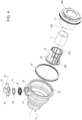
Figure 4 is an exploded view of the connecting member inFigure 3 , -
Figure 5 is a longitudinal cross section of the connecting member inFigure 3 , -
Figure 6 is a view from above of the connecting member inFigure 3 , and -
Figure 7 is a front view of an internal combustion engine according to the prior art. - In
Figure 1 , the reference number 1 is used to indicate, as a whole, a motor vehicle. - The motor vehicle 1 comprises a
body 2, itself comprising a chassis (not illustrated) and askin 3 that covers the chassis defining the external surfaces of motor vehicle 1. - In addition, the motor vehicle 1 comprises an
internal combustion engine 4, which in turn comprises acrankcase 5 supported by the chassis suspended from it. - More specifically, the
crankcase 5 is suspended on the chassis, especially by means of elastic suspension elements of a known type not illustrated, more specifically made of an elastomeric material. - Therefore, the
crankcase 5 is coupled in a movable manner relative to the chassis, although in particular the movements of thecrankcase 5 relative to the chassis elicit reactions from the suspension elements that tend to bring thecrankcase 5 back to a stable equilibrium relative to the chassis. - The
engine 4 also comprises anintake manifold 7 and, in detail, a plurality of cylinders (not illustrated) that communicate with theintake manifold 7 via respective intake valves to take in air collected in theintake manifold 7. - The
engine 4 also includes anintake line 8 that includes anair intake 9 and extends from theair intake 9 to theintake manifold 7. - The
air intake 9 is adapted to draw in outside air while the motor vehicle 1 is being used. In other words, theair intake 9 is exposed to the outside of the motor vehicle 1 and more precisely to an aerodynamic flow that is generated during the use of the motor vehicle 1 and strikes theskin 3. - The
air intake 9 is in particular formed on theskin 3. - The
intake line 8 is configured to conduct the air drawn through theair intake 9 to theintake manifold 7. - In detail, the air directed to the
intake manifold 7 is compressed along theintake line 8, whereby the latter includes a compressor C, for example of a known type only schematically illustrated. - The compressor C is part of a turbocharger for supercharging the
engine 4. - The compressor C has an inlet duct attached to the
crankcase 5 and is configured to feed air into the compressor C. - The
air intake 9 is fixed relative to the chassis, so thecrankcase 5 and, more precisely, the compressor C may move relative to theair intake 9. - Downstream of the
air intake 9, theintake line 8 preferably also includes anair filter 10 configured to filter the air drawn from theair intake 9. - Downstream of the
optional air filter 10 or, in any case, downstream of theair intake 9, theintake line 8 comprises aduct 11 extending towards the inlet duct for feeding air into the compressor C, or, more generally, towards theintake manifold 7, the compressor C being an optional component. In addition, theintake line 8 includes aflexible sleeve 12 that, in particular, connects theduct 11 to the inlet duct for feeding air into the compressor C or, more generally, to a duct attached to thecrankcase 5. - As can be seen in
Figure 2 , irrespective of the other characteristics of theengine 4, theflexible sleeve 12 is most notably interposed directly or immediately between theduct 11 and the duct attached to thecrankcase 5, that is, it is immediately downstream of theduct 11 and immediately upstream of the duct attached tocrankcase 5. - The
duct 11 is fixed relative to theair intake 9 and, thus, to the chassis, so the flexibility of thesleeve 12 allows relative movements between thecrankcase 5 or the duct attached to it and theduct 11. - In other words, the
sleeve 12 is more flexible than theduct 11 and the duct attached to the crankcase 5 (in particular, the inlet duct for feeding air to the compressor C) . - Downstream of the compressor C, the
intake line 8 optionally includes anintercooler 13 to cool the compressed air emitted by the compressor C before it reaches theintake manifold 7. Theintercooler 13 is therefore arranged between theintake manifold 7 and the compressor C and may, for example, be of a known type, so its operation will not be described in further detail. - The
sleeve 12 is more generally part of a connecting member (Figures 3 ,4 ) of theintake line 8. This connecting member is arranged between theair intake 9 and theintake manifold 7, and more precisely between theduct 11 and the compressor C or the inlet duct for feeding air into the compressor C. - The connecting member also comprises an
intake resonator 14, anozzle 15, and, preferably, aconnector 16 adapted for the connection of a duct (not shown) for recirculating lubricating oil vapours in theintake manifold 7, that is, a lubricating oil vapour recirculation duct. - The leakage of lubricating oil vapours from inside the cylinders towards the
crankcase 5 is known by the English expression "blow-by". In practice, thecrankcase 5 has a vent directed towards the lubricating oil vapour recirculation duct, so that the lubricating oil vapours that leak from the cylinders can be blown from thecrankcase 5 and be recirculated along theintake line 8 to theintake manifold 7. - The
sleeve 12 extends along a longitudinal axis X, for example coinciding with the forward direction of the motor vehicle 1. - The
sleeve 12 also extends axially, that is, along the axis X, between an inlet opening 20 and an outlet opening 21 that are opposite each other along the axis X and, respectively, closer to the air intake 9 (more precisely, to the duct 11) and to the intake manifold 7 (more precisely, to the compressor C or to the inlet duct for feeding air into the compressor C). - The
sleeve 12 has a radiallyouter surface 22 and a radiallyinner surface 23; the latter defines an inner volume V of thesleeve 12. - The
sleeve 12 is preferably bellows-shaped, that is, with at least one of thesurfaces surfaces - In addition, the
sleeve 12 preferably has an axially tapered shape towards the compressor C or towards theoutlet opening 21; more precisely, the geometry of thesleeve 12 is axially tapered from the inlet opening 20 to theoutlet opening 21. - The
inlet opening 20 is defined by anaxial end 24 of thesleeve 12, just as theoutlet opening 21 is independently defined by anaxial end 25 of thesleeve 12 opposite theaxial end 24. - The
axial end 25 is connected to thecrankcase 5 or, more precisely, to the inlet duct for feeding air to the compressor C, so that theoutlet opening 21 communicates, in detail, with this inlet duct. - The
nozzle 15 defines aninlet orifice 27 in thesleeve 12. Theinlet orifice 27 is therefore a through hole across thesleeve 12, in detail extending in a radial direction R with respect to the axis X. Theinlet orifice 27 therefore creates a communication between the exterior of thesleeve 12 and the inner volume V. In other words, theinlet orifice 27 communicates with the inner volume V, that is, with the inside of thesleeve 12. - The
sleeve 12 preferably comprises an elastomeric material or, more precisely, is made of elastomeric material. - The
nozzle 15 is arranged on the radiallyouter surface 22. In particular, thenozzle 15 extends radially from the radiallyouter surface 22. - In particular, the
nozzle 15 is axially closer to the inlet opening 20 than to theoutlet opening 21. - In addition, more specifically, the
nozzle 15 comprises abayonet coupling body 26 for a bayonet coupling of theconnector 16 to thenozzle 15. - In addition, the
nozzle 15 includes asupport portion 40 to which thebayonet coupling body 26 is attached. In more detail, thebayonet coupling body 26 is co-moulded with thesupport portion 40. - In the embodiment illustrated, the
support portion 40 comprises a tubular body projecting from the radiallyouter surface 22 of thesleeve 12 and extending from the radiallyouter surface 22, in particular radially, to terminate with an end to which thebayonet coupling body 26 is attached. - However, the projecting tubular body is not strictly necessary; the
support portion 40 could also have had different shapes to the one described and illustrated. For example, thesupport portion 40 could correspond to the bottom of a cavity in the radiallyouter surface 22, without loss of generality. - The
bayonet coupling body 26 has a through hole with one end matching theinlet orifice 27. - The
support portion 40 preferably forms a single body with thesleeve 12, whereby thesupport portion 28 is more preferably made of the same material as thesleeve 12. - The
bayonet coupling body 26 preferably includes or is made of a plastic material that is different from that of thesleeve 12. - The
resonator 14 is configured to reduce the noise produced by the air flow through theintake line 7, in particular due to the operation of the compressor C. - The
resonator 14 is attached to thesleeve 12 and extends axially along the axis X at least partially inside the volume V, that is, inside thesleeve 12. - The
resonator 14 comprises a radially outermosttubular body 28 and a radiallyinnermost cage 29 coaxial and attached to thebody 28. - In addition, the
resonator 14 comprises sound-absorbing material F radially interposed between thebody 28 and thecage 29. - The
cage 29 is essentially a tubular body withradial openings 30 to allow the air flow axially crossing thecage 29 to escape into the radial gap between thebody 28 and thecage 29 and then re-enter thecage 29 by interacting with the sound-absorbing material. - The operating principles of the
resonator 14 are known and will not, therefore, be described in further detail. - The
cage 29 and thebody 28 are welded together, particularly after assembly with the sound-absorbing material. - Therefore, the
resonator 14 actually comprises two tubes that are concentric and coaxial with each other, so that they are inside each other, as well as radially communicating with each other by means of theradial openings 30. - The
body 28 axially terminates at its ends with twoopposite openings cage 29 terminating axially at its ends with twoopenings - The end defining the
opening 29b axially plugs a circular crown portion of theopening 28b, so that theopening 29b coincides with the remaining circular portion of theopening 28b. - The same essentially applies to the end defining the
opening 29a with theopening 28a, although, in detail, the radial dimension of the plugged circular crown portion is smaller. - In practice, particularly in light of the above, the
resonator 14 as a whole has an axial inlet opening, coinciding, in detail, with theopening 29a, and an axial outlet opening, coinciding, in detail, with theopening 29b. - The
opening 29b is arranged inside thesleeve 12, so it communicates with the inner volume V or with the inside of thesleeve 12, in particular directly. - The
opening 29a is arranged in theintake line 8 to receive the air flow directed from theair intake 9 to theintake manifold 7. - Therefore, the air flow enters the
resonator 14 through theopening 29a and exits it through theopening 29b, in particular by partly passing through the radial gap between thecage 29 and thebody 28. - As can be seen in
Figure 3 , theresonator 14 is arranged to plug the inlet opening 20 of thesleeve 12. - More specifically, the
body 28 radially occupies theinlet opening 20. Thebody 28 is also specifically attached to theduct 11, for example by means of a bayonet coupling. - The
resonator 14 is preferably glued to the radiallyinner surface 23, more precisely at theinlet opening 20. - In particular, the
body 28 comprises aninner core 31 and aring 32 attached to thecore 31 and radially surrounding thecore 31. Thering 32 has a radially inner surface attached to thecore 31 and a radially outer surface glued, specifically directly, to thesleeve 12 or, more precisely, to the radiallyinner surface 23 thereof. - The
ring 32 is preferably internally threaded, while thecore 31 is externally threaded, whereby thecore 31 is attached to thering 32 by screwing on thering 32. - The
ring 32 is, for example, metallic. Independently, thebody 28 and thecage 29 comprise or are made of respective plastic materials that are different to that of thesleeve 12. - The
connector 16 comprises anupper element 33, in particular including atubular element 34 with an axis having two straight portions orthogonal to each other, one of which is radial to the axis X. - The
tubular element 34 can be connected to the lubricating oil vapour recirculation duct to receive the lubricating oil vapours. - The
connector 16 also includes alower element 35 bayonet-coupled to thebayonet coupling body 26. - In addition, the
connector 16 includes amembrane 36 interposed between theelements connector 16. - The
elements membrane 36 sandwiched between them. - Conveniently, the
elements sleeve 12. Themembrane 36 could be metallic and, in detail, with steel, specifically spring steel. - The
connector 16 comprises a check valve, in detail comprising theelements membrane 36 interposed between them. - The check valve is configured to limit a return of the lubricating oil vapours to the lubricating oil vapour recirculation duct.
- More specifically, the
membrane 36 is provided with acentral hole 37 calibrated to limit the return of the vapours. - From the above, the advantages of the
internal combustion engine 4 according to the invention are clear. - The
engine 4 connecting member combines the functions of three components that are typically separated according to the prior art, thus constituting a clear saving of space in the motor vehicle 1. - In addition, the connecting member is particularly compact both axially and radially, for example due to the insertion of the
resonator 14 into thesleeve 12 and the radial integration of thenozzle 15 to thesleeve 12. - Finally, it is clear that changes may be made to the
internal combustion engine 4 according to the invention, and variations produced thereof, that, in any case, do not depart from the scope of protection defined by the claims. - In particular, the number and shape of the components described and illustrated could be different.
Claims (14)
- An internal combustion engine (4) for a motor vehicle (1), the internal combustion engine (4) comprising a crankcase (5), an intake manifold (7), and an intake line (8) extending from an air intake (9) to draw outside air to the intake manifold (8), the intake line (8) comprising a connecting member arranged between the air intake (9) and the intake manifold (7) and comprising in turn- a flexible sleeve (12) extending along a longitudinal axis (X),- an intake resonator (14) attached to the flexible sleeve (12) and extending axially along the longitudinal axis (X) at least partially within the flexible sleeve (12), and- a nozzle (15) on a radially outer surface (22) of the flexible sleeve (12) to define an inlet orifice (27) in the flexible sleeve (12).
- The internal combustion engine according to claim 1, wherein the flexible sleeve (12) is bellows-shaped.
- The internal combustion engine according to claim 1 or 2, wherein the intake line (8) comprises a first duct (11) attached to the air intake (9) and extending towards the intake manifold (7) downstream of the air intake (9), as well as a second duct attached to the crankcase (5), the flexible sleeve (12) connecting the first duct (11) to the second duct and being more flexible than the first duct (11) and the second duct.
- The internal combustion engine according to any of the previous claims, wherein the nozzle (15) extends radially from the radially outer surface (22) of the flexible sleeve (12) .
- The internal combustion engine according to any of the previous claims, wherein the connecting member further comprises a connector (16) attached to the nozzle (15) and adapted for connecting a conduit for a recirculation in the intake manifold (7) of lubricating oil vapours.
- The internal combustion engine according to claim 5, wherein the connector (16) comprises a check valve (33, 35, 36) for limiting a return of lubricating oil vapours to said conduit.
- The internal combustion engine according to claim 5 or 6, wherein the nozzle (15) comprises a bayonet coupling body (26) for a bayonet coupling of the connector (16) to the nozzle (15).
- The internal combustion engine according to claim 7, wherein the nozzle (15) further comprises a support portion (40) co-moulded with the bayonet coupling body (26).
- The internal combustion engine according to any one of the preceding claims, wherein the intake resonator (14) has an axial inlet opening (29a) and an axial outlet opening (29b) opposite the axial inlet opening (29a) according to the longitudinal axis (X), the axial outlet opening (29b) being arranged within the flexible sleeve (12), and wherein the axial inlet opening (29a) is arranged to receive an airflow directed from the air intake (9) to the intake manifold (7), so that the airflow enters the intake resonator (14) through the axial inlet opening (29a) and exits the intake resonator (14) into the flexible sleeve (12) through the axial outlet opening (29b).
- The internal combustion engine according to claim 9, wherein the intake resonator (14) is arranged to plug an axial inlet opening (28a) of the flexible sleeve (12).
- The internal combustion engine according to any one of the preceding claims, wherein the intake resonator (14) is bonded to a radially inner surface (23) of the flexible sleeve (12).
- The internal combustion engine according to any one of the preceding claims, wherein the flexible sleeve (12) is bellows-shaped.
- The internal combustion engine according to any one of the preceding claims, wherein the flexible sleeve (12) is axially tapered toward the intake manifold (7).
- A motor vehicle (1) comprising a chassis and an internal combustion engine (4) according to any one of the preceding claims, wherein the air intake (9) is fixed relative to the chassis, and wherein the crankcase (5) is suspended on the chassis.
Applications Claiming Priority (1)
| Application Number | Priority Date | Filing Date | Title |
|---|---|---|---|
| IT102023000026691A IT202300026691A1 (en) | 2023-12-14 | 2023-12-14 | INTERNAL COMBUSTION ENGINE WITH IMPROVED INTAKE LINE |
Publications (1)
| Publication Number | Publication Date |
|---|---|
| EP4571093A1 true EP4571093A1 (en) | 2025-06-18 |
Family
ID=89897722
Family Applications (1)
| Application Number | Title | Priority Date | Filing Date |
|---|---|---|---|
| EP24219476.9A Pending EP4571093A1 (en) | 2023-12-14 | 2024-12-12 | Internal combustion engine with improved intake line |
Country Status (3)
| Country | Link |
|---|---|
| US (1) | US20250198373A1 (en) |
| EP (1) | EP4571093A1 (en) |
| IT (1) | IT202300026691A1 (en) |
Citations (4)
| Publication number | Priority date | Publication date | Assignee | Title |
|---|---|---|---|---|
| FR2913463A1 (en) * | 2007-03-09 | 2008-09-12 | Trelleborg Reims Soc Par Actio | Noise reducing device for motor vehicle, has resonator formed of base directly communicating with conduit via small section opening, and cover fixed on base for forming attenuation cavity, where base forms integral part of conduit |
| DE102008015626A1 (en) * | 2008-03-26 | 2009-10-01 | Dr. Ing. H.C. F. Porsche Aktiengesellschaft | Connector for connecting vacuum line with connection unit of air filter housing in internal combustion engine, has welding ring with molding that engages with projection in connection unit for connecting ring and unit as bayonet connection |
| US11248567B2 (en) * | 2020-02-04 | 2022-02-15 | Hyundai Motor Company | Intake structure of vehicle and method of mounting nipple to intake structure |
| WO2023196352A1 (en) * | 2022-04-06 | 2023-10-12 | Daimler Truck North America Llc | Vehicle air intake apparatuses and methods thereof |
-
2023
- 2023-12-14 IT IT102023000026691A patent/IT202300026691A1/en unknown
-
2024
- 2024-12-12 EP EP24219476.9A patent/EP4571093A1/en active Pending
- 2024-12-13 US US18/980,160 patent/US20250198373A1/en active Pending
Patent Citations (4)
| Publication number | Priority date | Publication date | Assignee | Title |
|---|---|---|---|---|
| FR2913463A1 (en) * | 2007-03-09 | 2008-09-12 | Trelleborg Reims Soc Par Actio | Noise reducing device for motor vehicle, has resonator formed of base directly communicating with conduit via small section opening, and cover fixed on base for forming attenuation cavity, where base forms integral part of conduit |
| DE102008015626A1 (en) * | 2008-03-26 | 2009-10-01 | Dr. Ing. H.C. F. Porsche Aktiengesellschaft | Connector for connecting vacuum line with connection unit of air filter housing in internal combustion engine, has welding ring with molding that engages with projection in connection unit for connecting ring and unit as bayonet connection |
| US11248567B2 (en) * | 2020-02-04 | 2022-02-15 | Hyundai Motor Company | Intake structure of vehicle and method of mounting nipple to intake structure |
| WO2023196352A1 (en) * | 2022-04-06 | 2023-10-12 | Daimler Truck North America Llc | Vehicle air intake apparatuses and methods thereof |
Also Published As
| Publication number | Publication date |
|---|---|
| US20250198373A1 (en) | 2025-06-19 |
| IT202300026691A1 (en) | 2025-06-14 |
Similar Documents
| Publication | Publication Date | Title |
|---|---|---|
| US8485311B2 (en) | Air duct assembly for engine | |
| US10480537B2 (en) | Low-cost evacuator for an engine having tuned Venturi gaps | |
| CN101240762B (en) | Engine air intake system with resilient coupling having internal noise attenuation tuning | |
| JP2012082840A (en) | Two-way valve for turbocharged engine pcv system | |
| KR20160082513A (en) | Noise attenuation device for compressor inlet duct | |
| CN108361438B (en) | Bypass check valve and venturi device having the same | |
| EP4571093A1 (en) | Internal combustion engine with improved intake line | |
| US7950363B2 (en) | Air inlet system for internal combustion engine | |
| KR102258249B1 (en) | Evacuator system for supplying high suction vacuum or high suction flow rate | |
| US6647941B2 (en) | Air-routing system, especially a suction system of an internal combustion engine | |
| CN111075617B (en) | Air filter with built-in valve and its intake system | |
| CN208996847U (en) | Intake muffler system and engine | |
| JP7035129B2 (en) | Venturi device with check valve and check valve | |
| CN108506128A (en) | Intake muffler and vehicle with it | |
| EP3430269B1 (en) | A compressor arrangement supplying charged air to a combustion engine | |
| CN108331686B (en) | Air intake device for internal combustion engine | |
| CN103174562A (en) | Arrangement of a suction device for an auxiliary apparatus | |
| US7793757B2 (en) | Resonator with internal supplemental noise attenuation device | |
| CN211203060U (en) | Carbon tank solenoid valve | |
| CN109311466B (en) | Bypass valve in devices for generating vacuum | |
| CN221169740U (en) | Engine and generator | |
| KR20210132775A (en) | Continuous varialble trim compressor | |
| CN214366270U (en) | Filter with simple structure | |
| CN109958561B (en) | Air intake part, air filter and motor vehicle | |
| JP6981300B2 (en) | Evaporative fuel processing equipment |
Legal Events
| Date | Code | Title | Description |
|---|---|---|---|
| PUAI | Public reference made under article 153(3) epc to a published international application that has entered the european phase |
Free format text: ORIGINAL CODE: 0009012 |
|
| STAA | Information on the status of an ep patent application or granted ep patent |
Free format text: STATUS: THE APPLICATION HAS BEEN PUBLISHED |
|
| AK | Designated contracting states |
Kind code of ref document: A1 Designated state(s): AL AT BE BG CH CY CZ DE DK EE ES FI FR GB GR HR HU IE IS IT LI LT LU LV MC ME MK MT NL NO PL PT RO RS SE SI SK SM TR |
|
| STAA | Information on the status of an ep patent application or granted ep patent |
Free format text: STATUS: REQUEST FOR EXAMINATION WAS MADE |
|
| 17P | Request for examination filed |
Effective date: 20251218 |