EP4571069A1 - Système d'alimentation en carburant - Google Patents
Système d'alimentation en carburant Download PDFInfo
- Publication number
- EP4571069A1 EP4571069A1 EP24215975.4A EP24215975A EP4571069A1 EP 4571069 A1 EP4571069 A1 EP 4571069A1 EP 24215975 A EP24215975 A EP 24215975A EP 4571069 A1 EP4571069 A1 EP 4571069A1
- Authority
- EP
- European Patent Office
- Prior art keywords
- fuel
- engine
- oil
- heat exchanger
- actuator
- Prior art date
- Legal status (The legal status is an assumption and is not a legal conclusion. Google has not performed a legal analysis and makes no representation as to the accuracy of the status listed.)
- Pending
Links
Images

Classifications
-
- F—MECHANICAL ENGINEERING; LIGHTING; HEATING; WEAPONS; BLASTING
- F02—COMBUSTION ENGINES; HOT-GAS OR COMBUSTION-PRODUCT ENGINE PLANTS
- F02C—GAS-TURBINE PLANTS; AIR INTAKES FOR JET-PROPULSION PLANTS; CONTROLLING FUEL SUPPLY IN AIR-BREATHING JET-PROPULSION PLANTS
- F02C7/00—Features, components parts, details or accessories, not provided for in, or of interest apart form groups F02C1/00 - F02C6/00; Air intakes for jet-propulsion plants
- F02C7/22—Fuel supply systems
- F02C7/224—Heating fuel before feeding to the burner
-
- F—MECHANICAL ENGINEERING; LIGHTING; HEATING; WEAPONS; BLASTING
- F02—COMBUSTION ENGINES; HOT-GAS OR COMBUSTION-PRODUCT ENGINE PLANTS
- F02K—JET-PROPULSION PLANTS
- F02K3/00—Plants including a gas turbine driving a compressor or a ducted fan
- F02K3/02—Plants including a gas turbine driving a compressor or a ducted fan in which part of the working fluid by-passes the turbine and combustion chamber
- F02K3/04—Plants including a gas turbine driving a compressor or a ducted fan in which part of the working fluid by-passes the turbine and combustion chamber the plant including ducted fans, i.e. fans with high volume, low pressure outputs, for augmenting the jet thrust, e.g. of double-flow type
- F02K3/06—Plants including a gas turbine driving a compressor or a ducted fan in which part of the working fluid by-passes the turbine and combustion chamber the plant including ducted fans, i.e. fans with high volume, low pressure outputs, for augmenting the jet thrust, e.g. of double-flow type with front fan
-
- F—MECHANICAL ENGINEERING; LIGHTING; HEATING; WEAPONS; BLASTING
- F02—COMBUSTION ENGINES; HOT-GAS OR COMBUSTION-PRODUCT ENGINE PLANTS
- F02C—GAS-TURBINE PLANTS; AIR INTAKES FOR JET-PROPULSION PLANTS; CONTROLLING FUEL SUPPLY IN AIR-BREATHING JET-PROPULSION PLANTS
- F02C3/00—Gas-turbine plants characterised by the use of combustion products as the working fluid
- F02C3/20—Gas-turbine plants characterised by the use of combustion products as the working fluid using a special fuel, oxidant, or dilution fluid to generate the combustion products
- F02C3/24—Gas-turbine plants characterised by the use of combustion products as the working fluid using a special fuel, oxidant, or dilution fluid to generate the combustion products the fuel or oxidant being liquid at standard temperature and pressure
-
- F—MECHANICAL ENGINEERING; LIGHTING; HEATING; WEAPONS; BLASTING
- F02—COMBUSTION ENGINES; HOT-GAS OR COMBUSTION-PRODUCT ENGINE PLANTS
- F02C—GAS-TURBINE PLANTS; AIR INTAKES FOR JET-PROPULSION PLANTS; CONTROLLING FUEL SUPPLY IN AIR-BREATHING JET-PROPULSION PLANTS
- F02C7/00—Features, components parts, details or accessories, not provided for in, or of interest apart form groups F02C1/00 - F02C6/00; Air intakes for jet-propulsion plants
- F02C7/12—Cooling of plants
- F02C7/14—Cooling of plants of fluids in the plant, e.g. lubricant or fuel
-
- F—MECHANICAL ENGINEERING; LIGHTING; HEATING; WEAPONS; BLASTING
- F02—COMBUSTION ENGINES; HOT-GAS OR COMBUSTION-PRODUCT ENGINE PLANTS
- F02C—GAS-TURBINE PLANTS; AIR INTAKES FOR JET-PROPULSION PLANTS; CONTROLLING FUEL SUPPLY IN AIR-BREATHING JET-PROPULSION PLANTS
- F02C7/00—Features, components parts, details or accessories, not provided for in, or of interest apart form groups F02C1/00 - F02C6/00; Air intakes for jet-propulsion plants
- F02C7/32—Arrangement, mounting, or driving, of auxiliaries
-
- F—MECHANICAL ENGINEERING; LIGHTING; HEATING; WEAPONS; BLASTING
- F02—COMBUSTION ENGINES; HOT-GAS OR COMBUSTION-PRODUCT ENGINE PLANTS
- F02C—GAS-TURBINE PLANTS; AIR INTAKES FOR JET-PROPULSION PLANTS; CONTROLLING FUEL SUPPLY IN AIR-BREATHING JET-PROPULSION PLANTS
- F02C7/00—Features, components parts, details or accessories, not provided for in, or of interest apart form groups F02C1/00 - F02C6/00; Air intakes for jet-propulsion plants
- F02C7/36—Power transmission arrangements between the different shafts of the gas turbine plant, or between the gas-turbine plant and the power user
-
- F—MECHANICAL ENGINEERING; LIGHTING; HEATING; WEAPONS; BLASTING
- F02—COMBUSTION ENGINES; HOT-GAS OR COMBUSTION-PRODUCT ENGINE PLANTS
- F02C—GAS-TURBINE PLANTS; AIR INTAKES FOR JET-PROPULSION PLANTS; CONTROLLING FUEL SUPPLY IN AIR-BREATHING JET-PROPULSION PLANTS
- F02C9/00—Controlling gas-turbine plants; Controlling fuel supply in air- breathing jet-propulsion plants
- F02C9/16—Control of working fluid flow
- F02C9/18—Control of working fluid flow by bleeding, bypassing or acting on variable working fluid interconnections between turbines or compressors or their stages
-
- F—MECHANICAL ENGINEERING; LIGHTING; HEATING; WEAPONS; BLASTING
- F05—INDEXING SCHEMES RELATING TO ENGINES OR PUMPS IN VARIOUS SUBCLASSES OF CLASSES F01-F04
- F05D—INDEXING SCHEME FOR ASPECTS RELATING TO NON-POSITIVE-DISPLACEMENT MACHINES OR ENGINES, GAS-TURBINES OR JET-PROPULSION PLANTS
- F05D2240/00—Components
- F05D2240/35—Combustors or associated equipment
-
- F—MECHANICAL ENGINEERING; LIGHTING; HEATING; WEAPONS; BLASTING
- F05—INDEXING SCHEMES RELATING TO ENGINES OR PUMPS IN VARIOUS SUBCLASSES OF CLASSES F01-F04
- F05D—INDEXING SCHEME FOR ASPECTS RELATING TO NON-POSITIVE-DISPLACEMENT MACHINES OR ENGINES, GAS-TURBINES OR JET-PROPULSION PLANTS
- F05D2260/00—Function
- F05D2260/20—Heat transfer, e.g. cooling
- F05D2260/213—Heat transfer, e.g. cooling by the provision of a heat exchanger within the cooling circuit
-
- Y—GENERAL TAGGING OF NEW TECHNOLOGICAL DEVELOPMENTS; GENERAL TAGGING OF CROSS-SECTIONAL TECHNOLOGIES SPANNING OVER SEVERAL SECTIONS OF THE IPC; TECHNICAL SUBJECTS COVERED BY FORMER USPC CROSS-REFERENCE ART COLLECTIONS [XRACs] AND DIGESTS
- Y02—TECHNOLOGIES OR APPLICATIONS FOR MITIGATION OR ADAPTATION AGAINST CLIMATE CHANGE
- Y02T—CLIMATE CHANGE MITIGATION TECHNOLOGIES RELATED TO TRANSPORTATION
- Y02T50/00—Aeronautics or air transport
- Y02T50/60—Efficient propulsion technologies, e.g. for aircraft
Definitions
- the present disclosure relates to aircraft actuation systems, and to methods of actuating actuation system fueldraulically.
- a gas turbine engine for an aircraft comprising:
- the inventors have appreciated that the use of fuels different from the traditional kerosene-based jet fuels, such as sustainable aviation fuels, may result in different fuel properties, and that these different fuel properties may enable actuators to be fueldraulically driven.
- some fuels may be heated to higher temperatures and used to drive at least one more actuator than traditional fuels, without significantly increasing the risk of thermal degradation of the fuel (e.g., fuel lacquer, or fuel coking) within the actuators.
- the bypass ratio is greater than or equal to 4, and may be in the range of 4-55.
- the bypass ratio may be in the range of 4-20.
- the bypass ratio may be in the range of 4-15.
- the fuel system may be arranged to:
- the fuel system may be arranged to select between actuating or bypassing multiple fueldraulic actuators based on the SAF content of the fuel.
- One or more of the fueldraulic actuators may have a different threshold from each other - for example, the fuel system may be arranged to cause the fuel to actuate a first actuator when the SAF content of the fuel is above a first threshold or to bypass that actuator otherwise, and to cause the fuel to actuate a second actuator when the SAF content of the fuel is above a second threshold which is higher than the first threshold, or to bypass that actuator otherwise.
- the core shaft may output drive to the fan directly, so as to drive the fan at the same rotational speed as core shaft.
- Such an engine may be a direct drive turbine engine.
- the turbine engine may comprise a gearbox that receives an input from the core shaft and outputs drive to the fan so as to drive the fan at a lower rotational speed than the core shaft.
- Such an engine may be a geared turbine engine.
- the engine may comprise a turbine case cooling - TCC - system.
- the plurality of actuators may comprise an actuator which is part of the turbine case cooling system.
- the fuel supply system may be configured to actuate or bypass the actuator which is part of a turbine case cooling system based on the SAF content of the fuel.
- At least two of the plurality of actuators may be a part of the turbine case cooling system.
- the fuel supply system may be arranged to supply fuel to fueldraulically drive the at least two of the plurality of actuators which are part of the TCC system.
- the fuel supply system may be configured to actuate or bypass the at least two actuators which are part of a turbine case cooling system based on the SAF content of the fuel.
- the engine may comprise a cabin bleed valve.
- the plurality of actuators may comprise an actuator configured to actuate the cabin bleed valve.
- the fuel supply system may be configured to actuate or bypass the actuator configured to actuate the cabin bleed valve based on the SAF content of the fuel.
- the engine may comprise a handling bleed valve.
- the plurality of actuators may comprise an actuator configured to actuate the handling bleed valve.
- the fuel supply system may be configured to actuate or bypass the handling bleed valve based on the SAF content of the fuel.
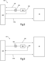
- the engine may comprise an engine heat management system comprising a valve.
- the plurality of actuators may comprise an actuator configured to actuate the valve within the engine heat management system.
- the fuel supply system may be configured to actuate or bypass the valve within the engine heat management system based on the SAF content of the fuel.
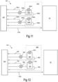
- the engine heat management system may comprise a heat exchanger.
- the heat exchanger may be an air-oil heat exchanger.
- the fuel supply system may be configured to actuate or bypass a valve on the air-side of the heat exchanger based on the SAF content of the fuel.
- the fuel supply system may be configured to actuate or bypass a valve on the oil-side of the heat exchanger based on the SAF content of the fuel.
- the heat exchanger may be a fuel-oil heat exchanger.
- the fuel supply system may be configured to actuate or bypass a valve on the fuel-side of the fuel-oil heat exchanger based on the SAF content of the fuel.
- the fuel supply system may be configured to actuate or bypass a valve on the oil-side of the fuel-oil heat exchanger based on the SAF content of the fuel.
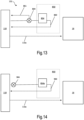
- the engine may comprise a generator heat management system comprising a valve.
- the plurality of actuators may comprise an actuator configured to actuate the valve within the generator heat management system.
- the fuel supply system may be configured to actuate or bypass the valve within the generator heat management system based on the SAF content of the fuel.
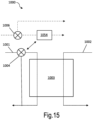
- the generator heat management system may comprise a heat exchanger.
- the heat exchanger may be an air-oil heat exchanger.
- the fuel supply system may be configured to actuate or bypass a valve on the air-side of the heat exchanger based on the SAF content of the fuel.
- the fuel supply system may be configured to actuate or bypass a valve on the oil-side of the heat exchanger based on the SAF content of the fuel.
- the heat exchanger may be a fuel-oil heat exchanger.
- the fuel supply system may be configured to actuate or bypass a valve on the fuel-side of the fuel-oil heat exchanger based on the SAF content of the fuel.
- the fuel supply system may be configured to actuate or bypass a valve on the oil-side of the fuel-oil heat exchanger based on the SAF content of the fuel.
- the at least one actuator may be actuated non-fueldraulically.
- the actuator When the fuel supply system bypasses the at least one actuator, the at least one actuator may be actuated non-fueldraulically.
- the actuator When the actuator is actuated non-fueldraulically, it may be actuated using a non-fuel hydraulic liquid.
- the non-fuel hydraulic liquid may be supplied via a non-return valve to avoid mixing.
- the fuel may be supplied to the actuator using a non-return valve to avoid mixing.
- the actuator may instead be electrically or pneumatically actuated.
- the fuel supply system may be arranged to cause the fuel to actuate the at least one actuator when the SAF content is above a threshold.
- the fuel supply system may be arranged to cause the fuel to bypass the at least one actuator when the SAF content is below the threshold.
- the minimum SAF content required for actuation of the at least one actuator may be at least 25%, 30%, 35%, 40%, 45%, 50%, 52%, 55%, 60%, 65%, 70%, or 75% by volume.
- the fuel supply system may be arranged to be controlled to make the selection between fueldraulic actuation and bypass for two or more of the plurality of actuators.
- the fuel supply system may be controllable to make the selection between fueldraulic actuation and bypass for two, three, four, or five actuators.
- the maximum differential operating pressure across that actuator during take-off conditions may be in the range from 6,900 kPa to 10,000 kPa, or may be greater than 10,000 kPa.
- the maximum differential operating pressure during take-off conditions may be greater than 7,000 kPa, 8,000 kPa, 9,000 kPa, 10,000 kPa 11,000 kPa, 12,000 kPa, 13,000 kPa, 14,000 kPa, or greater than 15,000 kPa.
- the maximum differential operating pressure during cruise conditions may be greater than or equal to 2400 kPa, greater than 2500 kPa, greater than 3000 kPa, greater than 3500 kPa, greater than 3800 kPa, or greater than 4000 kPa.
- the same actuator may see significantly less pressure at idle - for example with a differential pressure in the range from 1000 kPa to 1250 kPa (150-180 psid).
- a gas turbine engine for an aircraft comprising:
- the method may comprise:
- the method may comprise: supplying, using the fuel supply system, fuel to at least two of the plurality of actuators and, based on sustainable aviation fuel - SAF - content of the fuel, selecting between:
- the bypass decision may therefore be a single decision made for all relevant actuators, or may be a series of decisions taken for individual actuators.
- the bypass ratio may be in the range of 4-55.
- the bypass ratio may be in the range of 4-20.
- the bypass ratio may be in the range of 4-15.
- the method of the second aspect may be performed using the engine of the first aspect.
- the method may comprise increasing the fuel pressure flowing through the at least one fueldraulic actuator based on the SAF content of the fuel.
- the pressure may be increased by at least 350 kPa for every 5% increase in %SAF above 60% (volumetric%).
- One or more pumps and/or valves may be used to increase the pressure.
- a gas turbine engine for an aircraft comprising:
- the fuel comprises at least 25% sustainable aviation fuel- SAF - by volume.
- the fuel supply system is arranged such that a peak differential pressure of the fuel across the at least one fueldraulic actuator during cruise conditions is at least 2400 kPa (350 psid).
- differential pressure across an actuator will change depending on the operating conditions (e.g. fuel flow rate).
- the peak, or maximum, differential pressure is therefore selected for ease of comparison; this pressure is more specifically a steady-state peak differential pressure; i.e. any short-lived, transient, spikes in pressure are discounted.
- the steady-state peak value may therefore be a time-averaged pressure value, averaged over five, ten, fifteen, twenty, twenty five, or thirty seconds. The peak should last for a period of at least around five seconds, so excluding sharp transient spikes.
- the peak differential pressure of the fuel across the at least one fueldraulic actuator during cruise conditions may be at least 2500 kPa, 2600 kPa, 2750 kPa, 3000 kPa, 3200 kPa, 3400 kPa, 3500 kPa, 3600 kPa, 3700 kPa, 3800 kPa, or 4000 kPa.
- the peak differential pressure of the fuel across the at least one fueldraulic actuator during cruise conditions may be in the range from 2400 kPa to 4500 kPa, and optionally from 2500 kPa to 4000 kPA, or from 2500 kPa to 3800 kPA,
- the bypass ratio is greater than or equal to 4, and may be in the range of 4-55.
- the bypass ratio may be in the range of 4-20.
- the bypass ratio may be in the range of 4-15.
- the maximum differential operating pressure during take-off conditions may be in the range from 6,900 kPa to 10,000 kPa, or may be greater than 7,000 kPa, 8,000 kPa, 9,000 kPa, or 10,000 kPa.
- the same actuator may see significantly less pressure at idle - for example with a differential pressure in the range from 1000 kPa to 1250 kPa (150-180 psid).
- the core shaft may output drive to the fan directly, so as to drive the fan at the same rotational speed as core shaft, such that the engine is a direct drive turbine engine.
- the turbine engine may comprise a gearbox that receives an input from the core shaft and outputs drive to the fan so as to drive the fan at a lower rotational speed than the core shaft, such that the engine is a geared turbine engine.
- the fuel may comprise at least 50%, 55%, 60%, 65%, 70%, or 75% SAF by volume.
- the at least one fueldraulic actuator may be a variable stator vane actuator.
- the at least one fueldraulic actuator may be a variable inlet guide vane actuator.
- the engine of the third aspect may comprise any or all features of the engine of the first aspect, and may be used to implement the method of the second aspect.
- the engine comprises:
- the method comprises:
- Fuel of the same composition may be supplied to both the combustor and the at least one actuator.
- One or more controllable valves and/or pumps may be supplied to adjust the differential pressure of the fuel across the at least one fueldraulic actuator.
- the peak differential pressure of the fuel across the at least one fueldraulic actuator during cruise conditions may be at least 2500 kPa.
- the bypass ratio may be in the range of 4-55.
- the bypass ratio may be in the range of 4-20.
- the bypass ratio may be in the range of 4-15.
- the method may comprise controlling the supply of fuel to the one or more fueldraulic actuators so as to adjust the peak differential pressure of the fuel across the at least one fueldraulic actuator based on the SAF content of the fuel.
- the method may comprise supplying fuel comprising at least 50% SAF by volume, and controlling the fuel supply to the at least one actuator such that the peak differential pressure is at least 3200 kPa.
- the method may comprise supplying fuel comprising at least 55% SAF by volume, and controlling the fuel supply to the at least one actuator such that the peak differential pressure is at least 3550 kPa or 3600 kPa.
- the methods of the second and fourth aspects may be complementary, and may be performed together in various implementations.
- the method of the fourth aspect may be performed using the engine of the first aspect or the third aspect.
- a gas turbine engine for an aircraft comprising:
- the heat exchangers are controlled such that, under cruise conditions, a heat transfer ratio of: rate of heat transfer from oil to fuel in the secondary fuel ⁇ oil heat exchanger kJkg ⁇ 1 rate of heat transfer from oil to fuel in the primary and secondary fuel ⁇ oil heat exchangers kJkg ⁇ 1 has a maximum value of at least 0.35.
- heat transfer is measured per unit mass or volume of fuel in the examples described herein (with units of kJ per kg being noted above by way of example), so providing a heat transfer rate normalised for fuel flow rate variations at cruise. It will be appreciated that the heat transfer is noted per unit mass (kg) of fuel reaching the combustor so as to adjust for fuel flow rate and any recirculation through one or more of the heat exchangers or bypass of one or more of the heat exchangers as described elsewhere herein. In most implementations, it may be assumed that any temperature rise of the fuel due to other engine components (as opposed to due to heat transfer from the oil) is minimal.
- the maximum value for the heat transfer ratio may therefore be a time-averaged value, averaged over one, two, five, ten, fifteen, twenty, twenty-five, or thirty minutes. It will be appreciated that time scales for transient temperature changes may be greater than those for pressure in actuators - whereas the full movement of an actuator is likely to be completed within a few seconds, fuel and oil may spend longer within the heat exchangers.
- the heat transfer ratio may have a maximum value at cruise greater than 0.4.
- the heat transfer ratio may have a maximum value at cruise greater than 0.45.
- the heat transfer ratio may have a maximum value at cruise greater than 0.5.
- the bypass ratio is greater than or equal to 4, and may be in the range of 4-55.
- the bypass ratio may be in the range of 4-20.
- the bypass ratio may be in the range of 4-15.
- the maximum temperature of the fuel exiting the secondary fuel-oil heat exchanger may be at least 150°C, 160°C, 170°C, or 180°C.
- the primary and secondary heat exchangers may be arranged such that the heat transfer ratio is adjustable in operation of the engine, for example by controlling one or more pumps and/or valves so as to adjust fuel and/or oil flow through one or each heat exchanger.
- the heat exchangers may be arranged such that the heat transfer ratio is adjustable based on the sustainable aviation fuel - SAF - content of the fuel.
- the engine may comprise at least one bypass valve arranged to allow fuel or oil to bypass one of the fuel-oil heat exchangers, so as to adjust the heat transfer ratio.
- the engine may comprise one or more of:
- the engine may comprise at least one recirculation valve arranged to allow fuel or oil to pass through one of the fuel-oil heat exchangers multiple times, so as to adjust the heat transfer ratio.
- the engine may comprise one or more of:
- any of the recirculation valves described herein there may be one or more associated pumps configured to convey the oil/fuel back to the inlet of the heat exchanger, so as to pass through the heat exchanger again.
- any suitable components for repressurising the oil/fuel to enable recirculation may be used.
- the core shaft may output drive to the fan directly, so as to drive the fan at the same rotational speed as core shaft, such that the engine is a direct drive turbine engine.
- the engine of the fifth aspect may comprise any or all features of the engine of the first and/or third aspect, and may be used to implement the method of the second or fourth aspect.
- a sixth aspect there is provided a method of operating a gas turbine engine for an aircraft.
- the engine comprises:
- the method comprises:
- the bypass ratio may be in the range of 4-55.
- the bypass ratio may be in the range of 4-20.
- the bypass ratio may be in the range of 4-15.
- the method may further comprise adjusting the heat transfer ratio - for example by adjusting fuel and/or oil flow rate through one or each heat exchanger - based on the sustainable aviation fuel - SAF - content of the fuel.
- the methods of the second, fourth and sixth aspects may be complementary, and may be performed together, or in any combination or sub-combination, in various implementations.
- the method of the sixth aspect may be performed using the engine of the first aspect, third aspect, or fifth aspect.
- a gas turbine engine for an aircraft comprising:
- the bypass ratio is greater than or equal to 4, and may be in the range of 4-55.
- the bypass ratio may be in the range of 4-20.
- the bypass ratio may be in the range of 4-15.
- Thermally stable may refer to the ability of the fuel to satisfy the requirement of a Jet Fuel Thermal Oxidation Test (JFTOT).
- JFTOT Jet Fuel Thermal Oxidation Test
- Fuel which is thermally stable at temperature exceeding 280°C may refer to fuel which satisfied the requirements of a JFTOT test at temperatures greater than or equal to 280°C.
- the fuel may be thermally stable at temperatures equal to or exceeding 290°C, 295°C, 300°C, 305°C, 310°C, 315°C, 320°C, or 325°C.
- Aircraft gas turbine engines generally comprise a plurality of compressor vanes - the variable compressor vane actuator is arranged to adjust the position of a compressor vane.
- the vane is used to guide airflow, and as the position of the compressor vane is variable, it may be referred to as a variable guide vane.
- variable guide vanes of various implementations may include either or both of:
- the engine may comprise multiple variable stator vane actuators, which may each be fueldraulic. Further, the engine may comprise multiple compressors, each with at least one variable stator vane actuator.
- the gas turbine engine may comprise a plurality of variable compressor vanes, and multiple variable compressor vane actuators.
- the fuel supply system may be arranged to supply fuel to fueldraulically drive the multiple variable compressor vane actuators.
- the gas turbine engine may comprise at least two compressors, each compressor having at least one variable compressor vane and at least one variable compressor vane actuator associated therewith.
- the fuel supply system may be arranged to supply fuel to fueldraulically drive at least one variable compressor vane actuator of each compressor.
- the engine may comprise a turbine case cooling system.
- the plurality of actuators may comprise a turbine case cooling actuator.
- the fuel supply system may be arranged to supply fuel to fueldraulically drive the turbine case cooling actuator.
- An aircraft gas turbine engine generally comprises multiple servomotors (also referred to as servos), a servo being a rotary or linear actuator that allows for precise control of angular or linear position, velocity, and/or acceleration in a mechanical system.
- a servo being a rotary or linear actuator that allows for precise control of angular or linear position, velocity, and/or acceleration in a mechanical system.
- one, some, or all of the servos present may be fueldraulically actuated.
- One or more of the servos may comprise a sensor arranged to provide position feedback.
- a dedicated controller may be provided for the engine heat management system to control the one or more servos.
- the engine may comprise a servo within a hydro-mechanical unit.
- the plurality of actuators may comprise at least one actuator configured to actuate the servo within the hydro-mechanical unit.
- the fuel supply system may be arranged to supply fuel to fueldraulically drive the actuator configured to actuate the servo valve.
- Aromatics may make up less than 5% of the volume of the fuel.
- the calorific value of the fuel may be at least 43.5 MJkg -1 .
- the calorific value of the fuel may be at least 44 MJkg -1 .
- the sulphur content of the fuel may be below 15 parts per million.
- the fuel may be or comprise a HEFA fuel, i.e. a fuel made from Hydro-processed Esters and Fatty Acids.
- the core shaft may output drive to the fan directly, so as to drive the fan at the same rotational speed as the core shaft, such that the engine is a direct drive turbine engine.
- the turbine engine may comprise a gearbox that receives an input from the core shaft and outputs drive to the fan so as to drive the fan at a lower rotational speed than the core shaft, such that the engine is a geared turbine engine.
- the engine of the seventh aspect may comprise any or all features of the engine of the first, third and/or fifth aspect, and may be used to implement the method of the second, fourth or sixth aspect.
- the engine comprises:
- the bypass ratio is greater than or equal to 4 and may be in the range of 4-55.
- the bypass ratio may be in the range of 4-20.
- the bypass ratio may be in the range of 4-15.
- the method comprises:
- the fuel is thermally stable at temperatures exceeding 280°C.
- the methods of the second, fourth, sixth, and eighth aspects may be complementary, and may be performed together, or in any combination or sub-combination, in various implementations.
- the method of the eighth aspect may be performed using the engine of the first aspect, third aspect, fifth aspect, or seventh aspect.
- a gas turbine engine for an aircraft comprising:
- the at least one heat exchanger is arranged such that, at cruise, the fuel temperature on entry into the at least one actuator is at least 5°C greater than the fuel temperature on entry to the combustor.
- the bypass ratio is greater than or equal to 4, and may be in the range of 4-55.
- the bypass ratio may be in the range of 4-20.
- the bypass ratio may be in the range of 4-15.
- the at least one heat exchanger may be arranged such that, at cruise, the fuel temperature on entry into the at least one actuator is at least 7°C, 10°C, 12°C, 15°C, 20°C, 25°C, or 30°C greater than the fuel temperature on entry to the combustor.
- the core shaft may output drive to the fan directly, so as to drive the fan at the same rotational speed as core shaft, such that the engine is a direct drive turbine engine.
- the turbine engine may comprise a gearbox that receives an input from the core shaft and outputs drive to the fan so as to drive the fan at a lower rotational speed than the core shaft, such that the engine is a geared turbine engine.
- the at least one heat exchanger may comprise a primary fuel-oil heat exchanger arranged to heat at least the majority of the fuel, and a secondary fuel-oil heat exchanger arranged to provide additional heat to the fuel to be supplied to fueldraulically drive the at least one fueldraulic actuator.
- the primary and secondary fuel-oil heat exchangers may be controlled such that, under cruise conditions, a heat transfer ratio of: rate of heat transfer from oil to fuel in the secondary fuel ⁇ oil heat exchanger kJkg ⁇ 1 rate of heat transfer from oil to fuel in the primary and secondary fuel ⁇ oil heat exchangers kJkg ⁇ 1 has a maximum value of at least 0.35.
- the primary and secondary heat exchangers may be arranged such that the heat transfer ratio is adjustable in operation of the engine.
- the gas turbine engine may comprise at least one of the following to provide adjustment of the heat transfer ratio in operation:
- the fuel supply system may comprise a valve operable to enable fuel to bypass, or to recirculate through, the primary heat exchanger.
- the fuel supply system may comprise a valve operable to enable fuel to bypass, or to recirculate through, the secondary heat exchanger.
- the engine may be arranged to allow the heat transfer ratio to be adjusted based on the sustainable aviation fuel - SAF - content of the fuel. A higher heat transfer ratio may be allowed for higher fuel SAF contents.
- the fuel supply system may comprise, or have connected thereto, a fuel source.
- the fuel source may be located outside of the engine - e.g. a tank in a main fuselage of an aircraft or on a wing of an aircraft - and may not be a part of the engine.
- the fuel supplied to the at least one actuator to fueldraulically drive the at least one actuator may be supplied to the combustor after actuation without returning to the fuel source.
- the fuel may therefore be recirculated around the engine, or used in multiple ways within the engine, without being returned to a fuel tank.
- the fuel supplied to the combustor may comprise a mixture of fuel which has been passed through the at least one fuel-oil heat exchanger and fuel which has bypassed the at least one fuel-oil heat exchanger.
- the engine of the ninth aspect may comprise any or all features of the engine of the first, third, fifth, and/or seventh aspect, and may be used to implement the method of the second, fourth, sixth, and/or eighth aspect.
- a method of operating a gas turbine engine for an aircraft According to a tenth aspect, there is provided a method of operating a gas turbine engine for an aircraft.
- the engine comprises:
- the method comprises controlling the at least one heat exchanger such that, at cruise, the fuel temperature on entry into the at least one actuator is at least 5°C greater than the fuel temperature on entry to the combustor.
- the bypass ratio may be in the range of 4-55.
- the bypass ratio may be in the range of 4-20.
- the bypass ratio may be in the range of 4-15.
- the method may comprise determining at least one fuel characteristic of the fuel, and controlling a temperature difference between the fuel temperature on entry into the at least one actuator and the fuel temperature on entry to the combustor based on the at least one fuel characteristic.
- the fuel supply system may obtain the fuel from a fuel source such as an aircraft fuel tank (which is generally outside of the engine); and the method may be such that the fuel supplied to the at least one actuator to fueldraulically drive the at least one actuator is supplied to the combustor after actuation without returning to the fuel source.
- a fuel source such as an aircraft fuel tank (which is generally outside of the engine)
- the method may be such that the fuel supplied to the at least one actuator to fueldraulically drive the at least one actuator is supplied to the combustor after actuation without returning to the fuel source.
- the gas turbine engine may comprise primary and secondary fuel-oil heat exchangers, and the method may comprise controlling the primary and secondary fuel-oil heat exchangers such that, under cruise conditions, a heat transfer ratio of: rate of heat transfer from oil to fuel in the secondary fuel ⁇ oil heat exchanger kJkg ⁇ 1 rate of heat transfer from oil to fuel in the primary and secondary fuel ⁇ oil heat exchangers kJkg ⁇ 1 has a maximum value of at least 0.35.
- the method may comprise controlling the primary and secondary fuel-oil heat exchangers so as to adjust the heat transfer ratio based on the sustainable aviation fuel - SAF - content of the fuel.
- the methods of the second, fourth, sixth, eighth, and tenth aspects may be complementary, and may be performed together, or in any combination or sub-combination, in various implementations.
- the method of the tenth aspect may be performed using the engine of the first aspect, third aspect, fifth aspect, seventh aspect, or ninth aspect.
- gas turbine engine may be, for example, a turbofan gas turbine engine, an open rotor gas turbine engine (in which the propeller is not surrounded by a nacelle), a turboprop engine or a turbojet engine. Any such engine may or may not be provided with an afterburner.
- gas turbine engine may be, for example, configured for land or marine-based power generation applications.
- a gas turbine engine in accordance with any aspect of the present disclosure may comprise an engine core comprising a turbine, a combustor, a compressor, and a core shaft connecting the turbine to the compressor.
- a gas turbine engine may comprise a fan (having fan blades).
- a fan may be located upstream of the engine core.
- the gas turbine engine may comprise a fan located downstream of the engine core, for example where the gas turbine engine is an open rotor or a turboprop engine (in which case the fan may be referred to as a propeller).
- the gas turbine engine may comprise two contra-rotating propeller stages attached to and driven by a free power turbine via a shaft.
- the propellers may rotate in opposite senses so that one rotates clockwise and the other anti-clockwise around the engine's rotational axis.
- the gas turbine engine may comprise a propeller stage and a guide vane stage configured downstream of the propeller stage.
- the guide vane stage may be of variable pitch. Accordingly, high pressure, intermediate pressure, and free power turbines respectively may drive high and intermediate pressure compressors and propellers by suitable interconnecting shafts.
- the propellers may provide the majority of the propulsive thrust.
- one or more of the propellor stages may be driven by a gearbox.
- the gearbox may be of the type described herein.
- An engine according to the present disclosure may be a turbofan engine.
- Such an engine may be a direct-drive turbofan engine in which the fan is directly connected to the fan-drive turbine, for example without a gearbox, via a core shaft.
- the fan may be said to rotate at the same rotational speed as the fan-drive turbine.
- the fan-drive turbine may be a first turbine
- the core shaft may be a first core shaft
- the gas turbine engine may further comprise a second turbine and a second core shaft connecting the second turbine to the compressor.
- the second turbine, the compressor, and second core shaft may be arranged to rotate at a higher rotational speed than the first core shaft.
- the second turbine may be positioned axially upstream of the first turbine.
- An engine according to the present disclosure may be a geared turbofan engine.
- the engine has a fan that is driven via a gearbox.
- a gas turbine engine may comprise a gearbox that receives an input from the core shaft and outputs drive to the fan so as to drive the fan at a lower rotational speed than the core shaft.
- the input to the gearbox may be directly from the core shaft, or indirectly from the core shaft, for example via a spur shaft and/or gear.
- the core shaft may rigidly connect the turbine and the compressor, such that the turbine and compressor rotate at the same speed (with the fan rotating at a lower speed).
- the gas turbine engine as described and/or claimed herein may have any suitable general architecture.
- the gas turbine engine may have any desired number of shafts that connect turbines and compressors, for example one, two or three shafts.
- the turbine connected to the core shaft may be a first turbine
- the compressor connected to the core shaft may be a first compressor
- the core shaft may be a first core shaft.
- the engine core may further comprise a second turbine, a second compressor, and a second core shaft connecting the second turbine to the second compressor.
- the second turbine, second compressor, and second core shaft may be arranged to rotate at a higher rotational speed than the first core shaft.
- the second compressor may be positioned axially downstream of the first compressor.
- the second compressor may be arranged to receive (for example directly receive, for example via a generally annular duct) flow from the first compressor.
- the gearbox may be arranged to be driven by the core shaft that is configured to rotate (for example in use) at the lowest rotational speed (for example the first core shaft in the example above).
- the gearbox may be arranged to be driven only by the core shaft that is configured to rotate (for example in use) at the lowest rotational speed (for example only by the first core shaft, and not the second core shaft, in the example above).
- the gearbox may be arranged to be driven by any one or more shafts, for example the first and/or second shafts in the example above.
- the gearbox may be a reduction gearbox (in that the output to the fan is a lower rotational rate than the input from the core shaft).
- Any type of gearbox may be used.
- the gearbox may be a "planetary” or “star” gearbox, as described in more detail elsewhere herein.
- Such a gearbox may be a single stage.
- such a gearbox may be a compound gearbox, for example a compound planetary gearbox (which may have the input on the sun gear and the output on the ring gear, and thus be referred to as a "compound star” gearbox), for example having two stages of reduction.
- the gearbox may have any desired reduction ratio (defined as the rotational speed of the input shaft divided by the rotational speed of the output shaft), for example greater than 2.5, for example in the range of from 3 to 4.2, or 3.2 to 3.8, for example on the order of or at least 3, 3.1, 3.2, 3.3, 3.4, 3.5, 3.6, 3.7, 3.8, 3.9, 4, 4.1 or 4.2.
- the gear ratio may be, for example, between any two of the values in the previous sentence.
- the gearbox may be a "star” gearbox having a reduction ratio in the range of from 3.1 or 3.2 to 3.8.
- the gearbox may be a "star” gearbox having a reduction ratio in the range 3.0 to 3.1.
- the gearbox may be a "planetary” gearbox having a reduction ratio in the range 3.6 to 4.2. In some arrangements, the gear ratio may be outside these ranges.
- fuel of a given composition or blend is provided to a combustor, which may be provided downstream of the fan and compressor(s) with respect to the flowpath (for example axially downstream).
- the combustor may be directly downstream of (for example at the exit of) the second compressor, where a second compressor is provided.
- the flow at the exit to the combustor may be provided to the inlet of the second turbine, where a second turbine is provided.
- the combustor may be provided upstream of the turbine(s).
- each compressor may comprise any number of stages, for example multiple stages.
- Each stage may comprise a row of rotor blades and a row of stator vanes, which may be variable stator vanes (in that their angle of incidence may be variable).
- the row of rotor blades and the row of stator vanes may be axially offset from each other.
- the gas turbine engine may be a direct-drive turbofan gas turbine engine comprising 13 or 14 compressor stages (in addition to the fan).
- Such an engine may, for example, comprise 3 stages in the first (or "low pressure") compressor and either 10 or 11 stages in the second (or "high pressure”) compressor.
- the gas turbine engine may be a "geared” gas turbine engine (in which the fan is driven by a first core shaft via a reduction gearbox) comprising 11, 12 or 13 compressor stages (in addition to the fan).
- Such an engine may comprise 3 or 4 stages in the first (or “low pressure”) compressor and 8 or 9 stages in the second (or “high pressure”) compressor.
- the gas turbine engine may be a “geared” gas turbine engine having 4 stages in the first (or “low pressure”) compressor and 10 stages in the second (or “high pressure”) compressor.
- the or each turbine may comprise any number of stages, for example multiple stages. Each stage may comprise a row of rotor blades and a row of stator vanes, or vice versa, as required. The respective rows of rotor blades and stator vanes may be axially offset from each other.
- the second (or "high pressure") turbine may comprise 2 stages in any arrangement (for example regardless of whether it is a geared or direct-drive engine).
- the gas turbine engine may be a direct-drive gas turbine engine comprising a first (or "low pressure”) turbine having 5, 6 or 7 stages.
- the gas turbine engine may be a "geared” gas turbine engine comprising a first (or "low pressure”) turbine having 3 or 4 stages.
- Each fan blade may be defined as having a radial span extending from a root (or hub) at a radially inner gas-washed location, or 0% span position, to a tip at a 100% span position.
- the ratio of the radius of the fan blade at the hub to the radius of the fan blade at the tip may be less than (or on the order of) any of: 0.4, 0.39, 0.38, 0.37, 0.36, 0.35, 0.34, 0.33, 0.32, 0.31, 0.3, 0.29, 0.28, 0.27, 0.26, or 0.25.
- the ratio of the radius of the fan blade at the hub to the radius of the fan blade at the tip may be in an inclusive range bounded by any two of the values in the previous sentence (i.e.
- the values may form upper or lower bounds), for example in the range of from 0.28 to 0.32 or 0.29 to 0.30. These ratios may commonly be referred to as the hub-to-tip ratio.
- the radius at the hub and the radius at the tip may both be measured at the leading edge (or axially forwardmost) part of the blade.
- the hub-to-tip ratio refers, of course, to the gas-washed portion of the fan blade, i.e. the portion radially outside any platform.
- the radius of the fan may be measured between the engine centreline and the tip of a fan blade at its leading edge.
- the fan diameter (which may simply be twice the radius of the fan) may be greater than (or on the order of) any of: 140 cm, 170 cm, 180 cm, 190 cm, 200 cm, 210 cm, 220 cm, 230 cm, 240 cm, 250 cm (around 100 inches), 260 cm, 270 cm (around 105 inches), 280 cm (around 110 inches), 290 cm (around 115 inches), 300 cm (around 120 inches), 310 cm, 320 cm (around 125 inches), 330 cm (around 130 inches), 340 cm (around 135 inches), 350 cm, 360 cm (around 140 inches), 370 cm (around 145 inches), 380 cm (around 150 inches), 390 cm (around 155 inches), 400 cm, 410 cm (around 160 inches) or 420 cm (around 165 inches).
- the fan diameter may be in an inclusive range bounded by any two of the values in the previous sentence (i.e. the values may form upper or lower bounds), for example in the range of from 210 cm to 240 cm, or 250 cm to 280 cm, or 320 cm to 380 cm. Purely by way of non-limitative example, the fan diameter may be in the range of from 170 cm to 180 cm, 190 cm to 200 cm, 200 cm to 210 cm, 210 cm to 230 cm, 290 cm to 300 cm or 340 cm to 360 cm.
- the rotational speed of the fan may vary in use. Generally, the rotational speed is lower for fans with a higher diameter. Purely by way of non-limitative example, the rotational speed of the fan at cruise conditions may be less than 3500 rpm, for example less than 2600 rpm, or less than 2500 rpm, or less than 2300 rpm. Purely by way of further non-limitative example, the rotational speed of the fan at cruise conditions for a "geared" gas turbine engine having a fan diameter in the range of from 200 cm to 210 cm may be in the range of from 2750 to 2900 rpm.
- the rotational speed of the fan at cruise conditions for a "geared" gas turbine engine having a fan diameter in the range of from 210 cm to 230 cm may be in the range of from 2500 to 2800 rpm.
- the rotational speed of the fan at cruise conditions for a "geared" gas turbine engine having a fan diameter in the range of from 340 cm to 360 cm may be in the range of from 1500 to 1800 rpm.
- the rotational speed of the fan at cruise conditions for a direct drive engine having a fan diameter in the range of from 190 cm to 200 cm may be in the range of from 3600 to 3900 rpm.
- the rotational speed of the fan at cruise conditions for a direct drive engine having a fan diameter in the range of from 300 cm to 340 cm may be in the range of from 2000 to 2800 rpm.
- the fan In use of the gas turbine engine, the fan (with associated fan blades) rotates about a rotational axis. This rotation results in the tip of the fan blade moving with a velocity U tip .
- the work done by the fan blades on the flow results in an enthalpy rise dH of the flow.
- a fan tip loading may be defined as dH/U tip 2 , where dH is the enthalpy rise (for example the 1-D average enthalpy rise) across the fan and U tip is the (translational) velocity of the fan tip, for example at the leading edge of the tip (which may be defined as fan tip radius at leading edge multiplied by angular speed).
- the fan tip loading at cruise conditions may be greater than (or on the order of) any of: 0.28, 0.29, 0.30, 0.31, 0.32, 0.33, 0.34, 0.35, 0.36, 0.37, 0.38, 0.39 or 0.4 (all values being dimensionless).
- the fan tip loading may be in an inclusive range bounded by any two of the values in the previous sentence (i.e. the values may form upper or lower bounds), for example in the range of from 0.28 to 0.31, or 0.29 to 0.3 (for example for a geared gas turbine engine).
- Gas turbine engines in accordance with the present disclosure may have any desired bypass ratio (BPR), where the bypass ratio is defined as the ratio of the mass flow rate of the flow through the bypass duct to the mass flow rate of the flow through the core.
- BPR bypass ratio
- the bypass ratio at cruise conditions may be greater than (or on the order of) any of the following: 9. 9.5, 10, 10.5, 11, 11.5, 12, 12.5, 13, 13.5, 14, 14.5, 15, 15.5, 16, 16.5, 17, 17.5, 18, 18.5, 19, 19.5 or 20.
- the bypass ratio at cruise conditions may be in an inclusive range bounded by any two of the values in the previous sentence (i.e. the values may form upper or lower bounds), for example in the range of from 12 to 16, 13 to 15, or 13 to 14.
- the bypass ratio at cruise conditions of a direct-drive gas turbine engine according to the present disclosure may be in the range of from 9:1 to 11:1.
- the bypass ratio at cruise conditions of a geared gas turbine engine according to the present disclosure may be in the range of from 12:1 to 15:1
- the bypass duct may be at least substantially annular.
- the bypass duct may be radially outside the core engine.
- the radially outer surface of the bypass duct may be defined by a nacelle and/or a fan case.
- the overall pressure ratio (OPR) of a gas turbine engine as described and/or claimed herein may be defined as the ratio of the stagnation pressure at the exit of the highest pressure compressor (before entry into the combustor) to the stagnation pressure upstream of the fan.
- OCR overall pressure ratio
- the overall pressure ratio of a gas turbine engine as described and/or claimed herein at cruise conditions may be greater than (or on the order of) any of the following: 35, 40, 45, 50, 55, 60, 65, 70, 75.
- the overall pressure ratio may be in an inclusive range bounded by any two of the values in the previous sentence (i.e. the values may form upper or lower bounds), for example in the range of from 50 to 70.
- the overall pressure ratio at cruise conditions of a geared gas turbine engine having a fan diameter in the range of from 200 cm to 210 cm may be in the range of from 40 to 45.
- the overall pressure ratio at cruise conditions of a geared gas turbine engine having a fan diameter in the range of from 210 cm to 230 cm may be in the range of from 45 to 55.
- the overall pressure ratio at cruise conditions of a geared gas turbine engine having a fan diameter in the range of from 340 cm to 360 cm may be in the range of from 50 to 60.
- the overall pressure ratio at cruise conditions of a direct-drive gas turbine engine having a fan diameter in the range of from 300 cm to 340 cm may be in the range of from 50 to 60.
- Specific thrust of an engine may be defined as the net thrust of the engine divided by the total mass flow through the engine. In some examples, specific thrust may depend, for a given thrust condition, upon the specific composition of fuel provided to the combustor. At cruise conditions, the specific thrust of an engine described and/or claimed herein may be less than (or on the order of) any of the following: 110 Nkg -1 s, 105 Nkg -1 s, 100 Nkg -1 s, 95 Nkg -1 s, 90 Nkg -1 s, 85 Nkg -1 s or 80 Nkg -1 s. The specific thrust may be in an inclusive range bounded by any two of the values in the previous sentence (i.e.
- the values may form upper or lower bounds), for example in the range of from 80 Nkg -1 s to 100 Nkg -1 s, or 85 Nkg -1 s to 95 Nkg -1 s.
- Such engines may be particularly efficient in comparison with conventional gas turbine engines.
- the specific thrust of a geared gas turbine engine having a fan diameter in the range of from 200 cm to 210 cm may be in the range of from 90 Nkg -1 s to 95 Nkg -1 s.
- the specific thrust of a geared gas turbine engine having a fan diameter in the range of from 210 cm to 230 cm may be in the range of from 80 Nkg -1 s to 90 Nkg -1 s.
- the specific thrust of a geared gas turbine engine having a fan diameter in the range of from 340 cm to 360 cm may be in the range of from 70 Nkg -1 s to 90 Nkg -1 s.
- the specific thrust of a direct drive gas turbine engine having a fan diameter in the range of from 300 cm to 340 cm may be in the range of from 90 Nkg -1 s to 120 Nkg -1 s.
- a gas turbine engine as described and/or claimed herein may have any desired maximum thrust.
- a gas turbine as described and/or claimed herein may be capable of producing a maximum thrust of at least (or on the order of) any of the following: 100kN, 110kN, 120kN, 130kN, 135kN, 140kN, 145kN, 150kN, 155kN, 160kN, 170kN, 180kN, 190kN, 200kN, 250kN, 300kN, 350kN, 400kN, 450kN, 500kN, or 550kN.
- the maximum thrust may be in an inclusive range bounded by any two of the values in the previous sentence (i.e.
- a gas turbine as described and/or claimed herein may be capable of producing a maximum thrust in the range of from 155kN to 170kN, 330kN to 420kN, or 350kN to 400kN.
- the maximum thrust of a geared gas turbine engine having a fan diameter in the range of from 200 cm to 210 cm may be in the range of from 140kN to 160kN.
- the maximum thrust of a geared gas turbine engine having a fan diameter in the range of from 210 cm to 230 cm may be in the range of from 150kN to 200kN.
- the maximum thrust of a geared gas turbine engine having a fan diameter in the range of from 340 cm to 360 cm may be in the range of from 370kN to 500kN.
- the maximum thrust of a direct drive gas turbine engine having a fan diameter in the range of from 300 cm to 340 cm may be in the range of from 370kN to 500kN.
- the thrust referred to above may be the maximum net thrust at standard atmospheric conditions at sea level plus 15 degrees C (ambient pressure 101.3kPa, temperature 30 degrees C), with the engine static.
- the temperature of the flow at the entry to the high pressure turbine may be particularly high.
- This temperature which may be referred to as TET, may be measured at the exit to the combustor, for example immediately upstream of the first turbine vane, which itself may be referred to as a nozzle guide vane.
- TET may depend, for a given thrust condition, upon the specific composition of fuel provided to the combustor.
- the TET may be at least (or on the order of) any of the following: 1400K, 1450K, 1500K, 1520K, 1530K, 1540K, 1550K, 1600K or 1650K.
- the TET at cruise conditions of a geared gas turbine engine having a fan diameter in the range of from 200 cm to 210 cm may be in the range of from 1540K to 1600K.
- the TET at cruise conditions of a geared gas turbine engine having a fan diameter in the range of from 210 cm to 230 cm may be in the range of from 1590K to 1650K.
- the TET at cruise conditions of a geared gas turbine engine having a fan diameter in the range of from 340 cm to 360 cm may be in the range of from 1600K to 1660K.
- the TET at cruise conditions of a direct drive gas turbine engine having a fan diameter in the range of from 300 cm to 340 cm may be in the range of from 1590K to 1650K.
- the TET at cruise conditions of a direct drive gas turbine engine having a fan diameter in the range of from 300 cm to 340 cm may be in the range of from 1570K to 1630K.
- the TET at cruise conditions may be in an inclusive range bounded by any two of the values in the previous sentence (i.e. the values may form upper or lower bounds), for example 1530K to 1600K.
- the maximum TET in use of the engine may be, for example, at least (or on the order of) any of the following: 1700K, 1750K, 1800K, 1850K, 1900K, 1950K, 2000K, 2050K, or 2100K.
- the maximum TET of a geared gas turbine engine having a fan diameter in the range of from 200 cm to 210 cm may be in the range of from 1890K to 1960K.
- the maximum TET of a geared gas turbine engine having a fan diameter in the range of from 210 cm to 230 cm may be in the range of from 1890K to 1960K.
- the maximum TET of a geared gas turbine engine having a fan diameter in the range of from 340 cm to 360 cm may be in the range of from 1890K to 1960K.
- the maximum TET of a direct drive gas turbine engine having a fan diameter in the range of from 300 cm to 340 cm may be in the range of from 1935K to 1995K.
- the maximum TET of a direct drive gas turbine engine having a fan diameter in the range of from 300 cm to 340 cm may be in the range of from 1890K to 1950K.
- the maximum TET may be in an inclusive range bounded by any two of the values in the previous sentence (i.e. the values may form upper or lower bounds), for example in the range of from 1800K to 1950K, or 1900K to 2000K.
- the maximum TET may occur, for example, at a high thrust condition, for example at a maximum take-off (MTO) condition.
- MTO maximum take-off
- a fan blade and/or aerofoil portion of a fan blade described and/or claimed herein may be manufactured from any suitable material or combination of materials.
- at least a part of the fan blade and/or aerofoil may be manufactured at least in part from a composite, for example a metal matrix composite and/or an organic matrix composite, such as carbon fibre composite.
- at least a part of the fan blade and/or aerofoil may be manufactured at least in part from a metal, such as a titanium based metal or an aluminium based material (such as an aluminium-lithium alloy) or a steel based material.
- the fan blade may comprise at least two regions manufactured using different materials.
- the fan blade may have a protective leading edge, which may be manufactured using a material that is better able to resist impact (for example from birds, ice or other material) than the rest of the blade.
- a leading edge may, for example, be manufactured using titanium or a titanium-based alloy.
- the fan blade may have a carbon-fibre or aluminium based body (such as an aluminium lithium alloy) with a titanium leading edge.
- a fan as described and/or claimed herein may comprise a central portion, from which the fan blades may extend, for example in a radial direction.
- the fan blades may be attached to the central portion in any desired manner.
- each fan blade may comprise a fixture which may engage a corresponding slot in the hub (or disc).
- a fixture may be in the form of a dovetail that may slot into and/or engage a corresponding slot in the hub/disc in order to fix the fan blade to the hub/disc.
- the fan blades may be formed integrally with a central portion. Such an arrangement may be referred to as a bladed disc or a bladed ring.
- any suitable method may be used to manufacture such a bladed disc or bladed ring.
- at least a part of the fan blades may be machined from a block and/or at least part of the fan blades may be attached to the hub/disc by welding, such as linear friction welding.
- variable area nozzle may allow the exit area of the bypass duct to be varied in use.
- the general principles of the present disclosure may apply to engines with or without a VAN.
- the fan of a gas turbine as described and/or claimed herein may have any desired number of fan blades, for example 14, 16, 18, 20, 22, 24 or 26 fan blades. Where the fan blades have a carbon fibre composite body, there may be 16 or 18 fan blades. Where the fan blades have a metallic body (for example aluminium-lithium or titanium-alloy), there may be 18, 20 or 22 fan blades.
- the terms idle, taxi, take-off, climb, cruise, descent, approach, and landing have the conventional meaning and would be readily understood by the skilled person.
- the skilled person would immediately recognise each term to refer to the entirety, or one or more portions, of an operating phase of the engine within a given mission of an aircraft to which the gas turbine engine is designed to be attached.
- ground idle may refer to an operating phase of the engine where the aircraft is stationary and in contact with the ground, but where there is a requirement for the engine to be running.
- the engine may be producing between 3% and 9% of the available thrust of the engine.
- the engine may be producing between 5% and 8% of available thrust.
- the engine may be producing between 6% and 7% of available thrust.
- Taxi may refer to an operating phase of the engine where the aircraft is being propelled along the ground by the thrust produced by the engine. During taxi, the engine may be producing between 5% and 15% of available thrust. In further non-limitative examples, the engine may be producing between 6% and 12% of available thrust.
- the engine may be producing between 7% and 10% of available thrust.
- Take-off may refer to an operating phase of the engine where the aircraft is being propelled by the thrust produced by the engine. At an initial stage within the take-off phase, the aircraft may be propelled whilst the aircraft is in contact with the ground. At a later stage within the take-off phase, the aircraft may be propelled whilst the aircraft is not in contact with the ground.
- the engine may be producing between 90% and 100% of available thrust. In further non-limitative examples, the engine may be producing between 95% and 100% of available thrust. In further non-limitative examples, the engine may be producing 100% of available thrust.
- Climb may refer to an operating phase of the engine where the aircraft is being propelled by the thrust produced by the engine.
- the engine may be producing between 75% and 100% of available thrust.
- the engine may be producing between 80% and 95% of available thrust.
- the engine may be producing between 85% and 90% of available thrust.
- climb may refer to an operating phase within an aircraft flight cycle between take-off and the arrival at cruise conditions, the arrival at cruise conditions thus defining the onset of the cruise phase, or a portion thereof, of the aircraft flight.
- climb may refer to a nominal point in, or one or more nominal periods during, an aircraft flight cycle between take-off and landing, where a relative increase in altitude is required, which may require an additional thrust demand of the engine.
- cruise conditions which may define the cruise phase (or a portion thereof) of the aircraft flight, have the conventional meaning and would be readily understood by the skilled person.
- cruise conditions may refer to an the operating point of the engine at mid-cruise of a given mission (which may be referred to in the industry as the "economic mission") of an aircraft to which the gas turbine engine is designed to be attached.
- mid-cruise may be regarded as the point in an aircraft flight cycle at which 50% of the total fuel that is burned between top of climb and start of descent has been burned (which may be approximated by the midpoint - in terms of time and/or distance - between top of climb and start of descent).
- Cruise conditions may thus define an operating point, phase, or portion thereof, of the flight that provides a thrust that would ensure steady state operation (i.e. maintaining a constant altitude and/or a constant Mach Number), or at least a substantially steady state operation (i.e. maintaining an at least substantially constant altitude and/or an at least substantially constant Mach Number) of an aircraft to which it is designed to be attached, taking into account the number of engines provided to that aircraft. For example, where an engine is designed to be attached to an aircraft that has two engines of the same type, at cruise conditions the engine may provide half of the total thrust that would be required for steady state operation, or at least a substantially steady state operation, of that aircraft at mid-cruise.
- steady state operation i.e. maintaining a constant altitude and/or a constant Mach Number
- at least a substantially steady state operation i.e. maintaining an at least substantially constant altitude and/or an at least substantially constant Mach Number
- cruise conditions may be defined as the operating point of the engine that provides a specified thrust (required to provide - in combination with any other engines on the aircraft - a steady state operation, or at least a substantially steady state operation, of the aircraft to which it is designed to be attached at a given mid-cruise Mach Number) at the mid-cruise atmospheric conditions (defined by the International Standard Atmosphere according to ISO 2533 at the mid-cruise altitude).
- the mid-cruise thrust, atmospheric conditions and Mach Number are known, and thus the operating point of the engine at cruise conditions may be clearly defined.
- the forward speed at the cruise condition may be any point in the range of from Mach 0.7 to 0.9, for example 0.75 to 0.85, for example 0.76 to 0.84, for example 0.77 to 0.83, for example 0.78 to 0.82, for example 0.79 to 0.81, for example on the order of Mach 0.8, on the order of Mach 0.85 or in the range of from 0.8 to 0.85. Any single speed within these ranges may be part of the cruise condition. For some aircraft, the cruise conditions may be outside these ranges, for example below Mach 0.7 or above Mach 0.9.
- the cruise conditions may correspond to standard atmospheric conditions (according to the International Standard Atmosphere, ISA) at an altitude that is in the range of from 1 0000m to 15000m, for example in the range of from 1 0000m to 12000m, for example in the range of from 10400m to 11600m (around 38000 ft), for example in the range of from 10500m to 11500m, for example in the range of from 10600m to 11400m, for example in the range of from 10700m (around 35000 ft) to 11300m, for example in the range of from 10800m to 11200m, for example in the range of from 10900m to 11100m, for example on the order of 11000m.
- the cruise conditions may correspond to standard atmospheric conditions at any given altitude in these ranges.
- the cruise conditions may correspond to a forward Mach number of 0.8 and standard atmospheric conditions (according to the International Standard Atmosphere) at an altitude of 35000ft (10668m).
- the engine may provide a known required net thrust level.
- the known required net thrust level is, of course, dependent on the engine and its intended application and may be, for example, a value in the range of from 20kN to 40kN.
- the cruise conditions may correspond to a forward Mach number of 0.85 and standard atmospheric conditions (according to the International Standard Atmosphere) at an altitude of 38000ft (11582m).
- the engine may provide a known required net thrust level.
- the known required net thrust level is, of course, dependent on the engine and its intended application and may be, for example, a value in the range of from 35kN to 65kN.
- a gas turbine engine described and/or claimed herein may operate at the cruise conditions defined elsewhere herein.
- cruise conditions may be determined by the cruise conditions (for example the mid-cruise conditions) of an aircraft to which at least one (for example 2 or 4) gas turbine engine may be mounted in order to provide propulsive thrust.
- descent and approach refers to an operating phase within an aircraft flight cycle between cruise and landing of the aircraft, with approach in particular forming part of the landing and take-off (LTO) phase.
- the engine may be producing between 0% and 50% of available thrust. In further non-limitative examples, the engine may be producing between 25% and 40% of available thrust. In further non-limitative examples, the engine may be producing between 30% and 35% of available thrust.
- descent may refer to a nominal point in an aircraft flight cycle between take-off and landing, where a relative decrease in altitude is required, and which may require a reduced thrust demand of the engine.
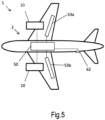
- an aircraft comprising a gas turbine engine as described and/or claimed herein.
- the aircraft according to this aspect is the aircraft for which the gas turbine engine has been designed to be attached. Accordingly, cruise conditions according to this aspect may correspond to an operating point, phase, or portion thereof, of the aircraft flight, as defined elsewhere herein.
- a method of operating a gas turbine engine as described and/or claimed herein may be at any suitable condition, which may be as defined elsewhere herein (for example in terms of the thrust, atmospheric conditions and Mach Number).
- a method of operating an aircraft comprising a gas turbine engine as described and/or claimed herein.
- the operation according to this aspect may include (or may be) operation at any suitable condition, for example the mid-cruise of the aircraft, as defined elsewhere herein.
- any parameter or value contained or described herein may be applied to and/or combined with any one or more further parameters and/or or values contained or described herein.
- a first parameter or value contained or described herein for example, parameter A
- any one or more further parameters and/or values contained or described herein for example, any one or more of parameter B; parameter C; and parameter D, and so on
- a product of their relationship may be expressed as, for example, A/B, B/A, B*A, or any such further application, combination, or function of parameter A relative to parameter B, as required.
- the core airflow A is accelerated and compressed by the low pressure compressor 14 and directed into the high pressure compressor 15 where further compression takes place.
- the compressed air exhausted from the high pressure compressor 15 is directed into the combustion equipment 16 where it is mixed with fuel F and the mixture is combusted.
- the combustion equipment 16 may be referred to as the combustor 16, with the terms “combustion equipment 16" and “combustor 16” used interchangeably herein.
- the resultant hot combustion products then expand through, and thereby drive, the high pressure and low pressure turbines 17, 19 before being exhausted through the nozzle 20 to provide some propulsive thrust.
- the high pressure turbine 17 drives the high pressure compressor 15 by a suitable interconnecting shaft 27.
- the fan 23 generally acts to impart increased pressure to the bypass airflow B flowing through the bypass duct 22, such that the bypass airflow B is exhausted through the bypass exhaust nozzle 18 to generally provide the majority of the propulsive thrust.
- the epicyclic gearbox 30 is a reduction gearbox.
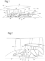
- FIG. 2 An exemplary arrangement for a geared fan gas turbine engine 10 is shown in Figure 2 .
- the low pressure turbine 19 (see Figure 1 ) drives the shaft 26, which is coupled to a sun wheel, or sun gear, 28 of the epicyclic gear arrangement 30.
- a sun wheel, or sun gear, 28 of the epicyclic gear arrangement 30 Radially outwardly of the sun gear 28 and intermeshing therewith is a plurality of planet gears 32 that are coupled together by a planet carrier 34.
- the planet carrier 34 constrains the planet gears 32 to precess around the sun gear 28 in synchronicity whilst enabling each planet gear 32 to rotate about its own axis.
- the planet carrier 34 is coupled via linkages 36 to the fan 23 in order to drive its rotation about the engine axis 9.
- an annulus or ring gear 38 Radially outwardly of the planet gears 32 and intermeshing therewith is an annulus or ring gear 38 that is coupled, via linkages 40, to a stationary supporting structure 24.
- low pressure turbine and “low pressure compressor” as used herein may be taken to mean the lowest pressure turbine stages and lowest pressure compressor stages (i.e. not including the fan 23) respectively and/or the turbine and compressor stages that are connected together by the interconnecting shaft 26 with the lowest rotational speed in the engine (i.e. not including the gearbox output shaft that drives the fan 23).
- the "low pressure turbine” and “low pressure compressor” referred to herein may alternatively be known as the "intermediate pressure turbine” and “intermediate pressure compressor”. Where such alternative nomenclature is used, the fan 23 may be referred to as a first, or lowest pressure, compression stage.
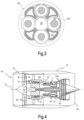
- the epicyclic gearbox 30 is shown by way of example in greater detail in Figure 3 .
- Each of the sun gear 28, planet gears 32 and ring gear 38 comprise teeth about their periphery to intermesh with the other gears. However, for clarity only exemplary portions of the teeth are illustrated in Figure 3 .
- Practical applications of a planetary epicyclic gearbox 30 generally comprise at least three planet gears 32.
- the epicyclic gearbox 30 illustrated by way of example in Figures 2 and 3 is of the planetary type, in that the planet carrier 34 is coupled to an output shaft via linkages 36, with the ring gear 38 fixed.
- the epicyclic gearbox 30 may be a star arrangement, in which the planet carrier 34 is held fixed, with the ring (or annulus) gear 38 allowed to rotate. In such an arrangement the fan 23 is driven by the ring gear 38.
- the gearbox 30 may be a differential gearbox in which the ring gear 38 and the planet carrier 34 are both allowed to rotate.
- any suitable arrangement may be used for locating the gearbox 30 in the engine 10 and/or for connecting the gearbox 30 to the engine 10.
- the connections (such as the linkages 36, 40 in the Figure 2 example) between the gearbox 30 and other parts of the engine 10 (such as the input shaft 26, the output shaft and the fixed structure 24) may have any desired degree of stiffness or flexibility.
- any suitable arrangement of the bearings between rotating and stationary parts of the engine may be used, and the disclosure is not limited to the exemplary arrangement of Figure 2 .
- the gearbox 30 has a star arrangement (described above)
- the skilled person would readily understand that the arrangement of output and support linkages and bearing locations would typically be different to that shown by way of example in Figure 2 .
- the present disclosure extends to a gas turbine engine having any arrangement of gearbox styles (for example star or planetary), support structures, input and output shaft arrangement, and bearing locations.
- gearbox styles for example star or planetary
- support structures for example star or planetary
- input and output shaft arrangement for example star or planetary
- bearing locations for example star or planetary
- the gearbox may drive additional and/or alternative components (e.g. the intermediate pressure compressor and/or a booster compressor).
- additional and/or alternative components e.g. the intermediate pressure compressor and/or a booster compressor.
- gas turbine engines to which the present disclosure may be applied may have alternative configurations.
- such engines may have an alternative number of compressors and/or turbines and/or an alternative number of interconnecting shafts.
- the gas turbine engine shown in Figure 1 has a split flow nozzle 18, 20 meaning that the flow through the bypass duct 22 has its own nozzle 18 that is separate to and radially outside the core engine nozzle 20.
- this is not limiting, and any aspect of the present disclosure may also apply to engines in which the flow through the bypass duct 22 and the flow through the core 11 are mixed, or combined, before (or upstream of) a single nozzle, which may be referred to as a mixed flow nozzle.
- One or both nozzles may have a fixed or variable area.
- gas turbine engines to which the present disclosure may be applied may have no gearbox for the main shaft(s), instead being direct drive engines.
- a cross-sectional view of one such engine is shown in Figure 4 .
- a gas turbine engine is generally indicated at 10, having a principal rotational axis 9.
- the engine 10 comprises, in axial flow series, an air intake 12, a propulsive fan 23, an intermediate pressure compressor 14, a high pressure compressor 15, combustion equipment 16, a high pressure turbine 17, an intermediate pressure turbine 19a, a low-pressure turbine 19 and an exhaust nozzle 20.
- a nacelle 21 surrounds the engine 10 and defines both the intake 12 and the exhaust nozzle 20.
- air entering the intake 12 is accelerated by the fan 23 to produce two air flows: a core airflow A and a bypass airflow B.
- the core airflow A flows into the intermediate pressure compressor 14, and the bypass air flow B passes through a bypass duct 22 to provide propulsive thrust.
- the intermediate pressure compressor 14 compresses the airflow A before delivering that air to the high pressure compressor 15 where further compression takes place.
- the compressed air exhausted from the high-pressure compressor 15 is directed into the combustion equipment 16 where it is mixed with fuel F and the mixture is combusted.
- the combustion equipment 16 may be referred to as the combustor 16, with the terms “combustion equipment 16" and “combustor 16” used interchangeably herein.
- the resultant hot combustion products then expand through, and thereby drive, the high, intermediate, and low-pressure turbines 17, 19a, 19 before being exhausted through the nozzle 20 to provide additional propulsive thrust.
- the high 17, intermediate 19a and low 19 pressure turbines drive respectively the high pressure compressor 15, intermediate pressure compressor 14 and fan 23, each by a suitable interconnecting shaft.
- gas turbine engines to which the present disclosure may be applied may have alternative configurations.
- such engines may have an alternative number of interconnecting shafts (e.g. two) and/or an alternative number of compressors and/or turbines.
- the engine may comprise a gearbox provided in the drive train from a turbine to a compressor and/or fan.
- turbofan engine Whilst the described example relates to a turbofan engine, the disclosure may apply, for example, to any type of gas turbine engine, such as an open rotor (in which the fan stage is not surrounded by a nacelle) or turboprop engine, for example.
- gas turbine engine 10 may not comprise a gearbox 30.
- the geometry of the gas turbine engine 10, and components thereof, is defined by a conventional axis system, comprising an axial direction (which is aligned with the rotational axis 9), a radial direction (in the bottom-to-top direction in Figure 1 ), and a circumferential direction (perpendicular to the page in the Figure 1 view).
- the axial, radial and circumferential directions are mutually perpendicular.
- the fuel F provided to the combustion equipment 16 may comprise a fossil-based hydrocarbon fuel, such as Kerosene.
- the fuel F may comprise molecules from one or more of the chemical families of n-alkanes, iso-alkanes, cycloalkanes, and aromatics.
- the fuel F may comprise renewable hydrocarbons produced from biological or non-biological resources, otherwise known as sustainable aviation fuel (SAF).
- SAF sustainable aviation fuel
- the fuel F may comprise one or more trace elements including, for example, sulphur, nitrogen, oxygen, inorganics, and metals.
- SAF is understood by the Skilled Person to refer to, for example, a biofuel, renewable aviation fuel, renewable jet fuel, alternative fuel or biojet fuel, produced from biological or non-biological resources.
- SAF is understood to be commonly synthesised from carbon-containing gasses drawn out of the atmosphere and/or captured from industrial processes; or from a wide range of sustainable feedstocks such as, for example, waste oil and fats; municipal solid waste; cellulosic waste (such as corn stalks); cover crops such as camelina, carinata, and pennycress; non-biogenic alternative fuels; jatropha; halophytes and algae, rather than from fossil-based hydrocarbons.
- SAF is understood as not encompassing fossil fuels.
- Functional performance of a given fuel composition, or blend of fuel F for use in a given mission may be defined, at least in part, by the ability of the fuel to service the Brayton cycle of the gas turbine engine 10.
- Parameters defining functional performance may include, for example, specific energy; energy density; thermal stability; and, emissions including gaseous and/or particulate matter.
- particulate matter emissions may include soot particles created by the combustion of said fuel F, also known as non-volatile particulate matter (nvPM). Any reference herein to soot or smoke may apply equally to other types of particulate matter emissions known within the art.
- Gaseous emissions may include any one or more of nitrogen oxides (NOx); carbon monoxide (CO); carbon dioxide (CO 2 ); unburned hydrocarbons (UHC); sulphur oxides (SO) including, for example, sulphur dioxide (SO 2 ) and/or sulphur trioxide (SOs); and, volatile organic compounds (VOC) created by the combustion of said fuel F.
- NOx nitrogen oxides
- CO carbon monoxide
- CO 2 carbon dioxide
- UHC unburned hydrocarbons
- SO sulphur oxides
- SO sulphur oxides
- SO 2 sulphur dioxide
- SOs volatile organic compounds
- VOC volatile organic compounds
- a relatively higher specific energy i.e. energy per unit mass
- a relatively higher energy density i.e. energy per unit volume
- a relatively higher thermal stability i.e. inhibition of fuel to degrade or coke under thermal stress
- reduced emissions may permit reduced contrail formation, whilst reducing the environmental impact of a given mission.
- Other properties of the fuel may also be key to functional performance.
- a relatively lower freeze point may allow long-range missions to optimise flight profiles; minimum aromatic concentrations (%) may ensure sufficient swelling of certain materials used in the construction of o-rings and seals that have been previously exposed to fuels with high aromatic contents; and, a maximum surface tension (mN/m) may ensure sufficient spray break-up and atomisation of the fuel.
- the ratio of the number of hydrogen atoms to the number of carbon atoms in a molecule may influence the specific energy of a given composition, or blend of fuel. Fuels with higher ratios of hydrogen atoms to carbon atoms may have higher specific energies in the absence of bond strain.
- fossil-based hydrocarbon fuels may comprise molecules with approximately 7 to 18 carbons, with a significant portion of a given composition stemming from molecules with 9 to 15 carbons, with an average of 12 carbons.
- a number of sustainable aviation fuel blends have been approved for use. For example, some approved blends comprise blend ratios of up to 10% sustainable aviation fuel, whilst other approved blends comprise blend ratios of between 10% and 50% sustainable aviation fuel (the remainder comprising one or more fossil-based hydrocarbon fuels, such as Kerosene), with further compositions awaiting approval.
- sustainable aviation fuel blends comprising up to (and including) 100% sustainable aviation fuel (SAF) will be eventually approved for use.
- Sustainable aviation fuels may comprise one or more of n-alkanes, iso-alkanes, cyclo-alkanes, and aromatics, and may be produced, for example, from one or more of synthesis gas (syngas); lipids (e.g. fats, oils, and greases); sugars; and alcohols.
- synthesis gas syngas
- lipids e.g. fats, oils, and greases
- sugars e.g. alcohols
- sustainable aviation fuels may comprise either or both of a lower aromatic and sulphur content, relative to fossil-based hydrocarbon fuels.
- sustainable aviation fuels may comprise either or both of a higher iso-alkane and cyclo-alkane content, relative to fossil-based hydrocarbon fuels.
- sustainable aviation fuels may comprise either or both of a density of between 90% and 98% that of kerosene and a calorific value of between 101% and 105% that of kerosene.
- the sustainable aviation fuel(s), or blend(s) provided to the combustion equipment 16 may be relatively lower in aromatic and/or other non-paraffinic content than that of kerosene.
- the sustainable aviation fuel may comprise an aromatic content of e.g. 30%, 20%, 15%, 10%, 8%, 5%, or less than 5%; e.g. 4%, 3%, 2%, 1%, or less than 1%; e.g. 0.75%, 0.5%, 0.25%, or less than 0.25%; e.g. 0.2%, 0.1 %, or less than 0.1%; e.g. 0.01%, 0.001 %, or 0%.
- the aromatic content of the sustainable aviation fuel may be in an inclusive figure or range bounded by or within any two of the values in the previous sentence (i.e. the values may form upper or lower bounds), e.g. 13.5%, 8.5%, 2.5%, 0.35%, 0.15%, 0.05%, 0.005%, or 0%; or 0% to 0.75%, 0% to 0.5%, or 0.1% to 0.25%; or 0.15% to 0.65%, 0.35% to 0.55%, or 0.035% to 0.055%; according to one or more of preference, fuel stock or supplier, and compositional variation therein.
- sustainable aviation fuels may provide benefits including, for example, one or more of a higher specific energy (despite, in some examples, a lower energy density); higher specific heat capacity; higher thermal stability; higher lubricity; lower viscosity; lower surface tension; lower freeze point; lower soot emissions; lower NOx; and, lower CO 2 emissions, relative to fossil-based hydrocarbon fuels (e.g. when combusted in the combustion equipment 16). Accordingly, relative to fossil-based hydrocarbon fuels, such as Kerosene, sustainable aviation fuels may lead to either or both of a relative decrease in specific fuel consumption, and a relative decrease in maintenance costs.
- an aircraft 1 may comprise multiple fuel tanks 50, 53a, b; for example a larger, primary fuel tank 50 located in the aircraft fuselage, and a smaller fuel tank 53a, 53b located in each wing.
- an aircraft 1 may have only a single fuel tank 50, and/or the wing fuel tanks 53a, b may be larger than the central fuel tank 50, or no central fuel tank 50 may be provided (with all fuel instead being stored in the aircraft's wings) - it will be appreciated that many different tank layouts are envisaged and that the examples pictured are provided for ease of description and not intended to be limiting.
- FIG. 5 shows an aircraft 1 with a propulsion system 2 comprising two gas turbine engines 10.
- the gas turbine engines 10 are supplied with fuel from a fuel supply system onboard the aircraft 1.
- the fuel supply system of the example pictured comprises a single fuel source.
- fuel source means either 1) a single fuel tank or 2) a plurality of fuel tanks which are fluidly interconnected.
- Each fuel source is arranged to provide a separate source of fuel (i.e., a first fuel source may contain a first fuel having a different characteristic or characteristics from a second fuel contained in a second fuel source).
- First and second fuel sources are therefore not fluidly coupled to each other so as to separate the different fuels (at least under normal running conditions).
- the use of multiple fuel sources allows an aircraft 1 to carry multiple different fuels, and to change which fuel is being used during operation, and optionally even whilst at cruise or when changing between different stages of operation in flight.
- the first (and, in these examples, only) fuel source comprises a centre fuel tank 50, located primarily in the fuselage of the aircraft 1 and a plurality of wing fuel tanks 53a, 53b, where at least one wing fuel tank is located in the port wing and at least one wing fuel tank is located in the starboard wing for balancing. All of the tanks 50, 53a, b are fluidly interconnected in the example shown, so forming a single fuel source. Each of the centre fuel tank 50 and the wing fuel tanks 53a, b may comprise a plurality of fluidly interconnected fuel tanks.
- the wing fuel tanks 53a, 53b may not be fluidly connected to the central tank 50, so forming a separate, second fuel source.
- one or more fuel tanks in the port wing may be fluidly connected to one or more fuel tanks in the starboard wing. This may be done either via a centre fuel tank (if that tank does not form part of the other fuel source), or bypassing the centre fuel tank(s), or both (for maximum flexibility and safety).
- the first fuel source comprises wing fuel tanks 53 and a centre fuel tank 50, while a second fuel source comprises a further separate centre fuel tank. Fluid interconnection between wing fuel tanks and the centre fuel tank of the first fuel source may be provided for balancing of the aircraft 1.
- two or more of the fuel sources may therefore contain different fuels from each other, such that the aircraft 1 can change fuel in flight. Being able to determine which fuel is being provided to the combustor 16 may therefore be more complex than simply recording a single identity of a fuel onboard the aircraft 1, or checking once at start-up.
- the allocation of fuel tanks 50, 53 available on the aircraft 1 may be constrained such that the first fuel source and the second fuel source are each substantially symmetrical with respect to the aircraft centre line.
- a suitable means of fuel transfer is generally provided between fuel tanks of the first fuel source and/or between fuel tanks of the second fuel source such that the position of the aircraft's centre of mass can be maintained within acceptable lateral limits throughout the flight.
- Aircraft generally refuel at multiple different airports, for example at the beginning and end of a long-distance flight. Whilst there are standards with which all aviation fuels must be compliant, as mentioned above, different aviation fuels have different compositions, for example depending on their source (e.g. different petroleum sources, biofuels or other synthetic aviation fuels (often described as sustainable aviation fuels - SAFs), and/or mixtures of petroleum-based fuels, and other fuels) and on any additives included (e.g. such as antioxidants and metal deactivators, biocides, static reducers, icing inhibitors, corrosion inhibitors) and any impurities.
- source e.g. different petroleum sources, biofuels or other synthetic aviation fuels (often described as sustainable aviation fuels - SAFs), and/or mixtures of petroleum-based fuels, and other fuels) and on any additives included (e.g. such as antioxidants and metal deactivators, biocides, static reducers, icing inhibitors, corrosion inhibitors) and
- fuel composition of the available aviation fuel may vary between batches even for a given airport or fuel supplier.
- fuel tanks 50, 53 of aircraft 1 are usually not emptied before being topped up for a subsequent flight, resulting in mixtures of different fuels within the tanks - effectively a fuel with a different composition resulting from the mixture.
- One or more fuel ports 62 may be provided for refuelling.
- FIG. 6 shows a schematic diagram representing a portion of a fuel supply system 152 of a gas turbine engine 10.
- the fuel supply system 152 comprises a main fuel flow path 110 from the fuel tank 50 to the combustor 16 of the gas turbine engine 10, and various branching fuel pathways taking fuel from, or returning fuel to, that main fuel flow path 110.
- the main fuel flow path 110 of the fuel supply system 152 acts as a source of fuel for fueldraulic systems.
- the gas turbine engine 10 comprises a combustor 16 and an actuator 154.
- the dashed arrows in Figure 6 represent the direction of fuel flow.
- One or more fuel lines 159, 160 are provided to supply fuel to an actuator 154, so as to fuedraulically actuate it.
- the fuel supply system 152 is arranged to supply fuel for combustion in the combustor 16.
- valves, pumps, sensors, offtakes for fueldraulic actuators, and heat exchangers may be present along the main fuel flow path 110, among other engine components.
- Fuel is supplied to the combustor 16 directly via line 110a, after passing through whichever prior engine component along the main fuel flow path 110 is furthest downstream.
- the fuel travelling via lines 159 and 160 is used to drive (i.e., actuate) the actuator 154.
- actuator 154 is fueldraulically driven.
- fueldraulic used herein refers to the hydraulic operation of an actuator with the hydraulic liquid being fuel. Actuators which are driven fueldraulically may be referred to herein as “fueldraulic actuators”.
- fuel travels to the actuator 154 from the fuel flow path 110 via line 159. After being used to fueldraulically drive the actuator 154, the fuel is returned to the main fuel flow path 110, via line 160, and may then be delivered to the combustor 16.
- the fuel return line 160 may comprise a valve configured to regulate the flow of fuel back to the main fuel path 110, and the valve may itself be operable using a fueldraulic actuator.
- the fuel return line 160 may direct fuel to a location along the main fuel flow path 110 which is before or after one or more heat exchangers of the main fuel flow path 110.
- the fuel return line 160 may return fuel to the fuel tank.
- the valve may be a fuel return-to-tank valve in such implementations.
- the fuel return-to-tank valve may be controlled using a fuel return-to-tank actuator.
- the fuel supply system may be arranged to supply fuel to fueldraulically drive the fuel return-to-tank actuator.
- Figure 6 shows a single fueldraulic actuator 154 on the fuel flow loop 159, 160.
- multiple fueldraulic actuators 154 may be located on a single fuel flow loop 159, 160, using fuel taken from a single point along the main fuel flow path 110.
- the multiple actuators may be arranged in series with respect to fuel flow (such that all of the fuel in the offtake pipe 159 passes through all actuators, in turn) or in parallel with respect to fuel flow (with the offtake pipe 159 branching and one or more actuators on each branch).
- FIG. 7 shows a schematic diagram representing an alternative portion of a fuel supply system 152 of a gas turbine engine 10.
- the fuel supply system 152 comprises a fuel source 50, 53, which may be a single fuel tank or multiple fuel tanks, and a fuel flow path 110 between the fuel source 50,53 and the combustor 16.
- the fuel supply system 152 shown comprises two actuators 254a, b, each on a separate fuel offtake loop from the main fuel flow path 110.
- the dashed arrows in Figure 7 represent the direction of fuel flow.
- Both actuators 254a,b are fueldraulically driven. That is to say, both actuators 254a,b are hydraulically actuated using fuel from the fuel source 50, 53 as the hydraulic liquid. Fuel travels from the main fuel flow path 110 to the actuators 254a,b respectively via lines 259a,b. After the fuel has been used to drive the actuators 254a,b, it returns to the main fuel flow pathway 110 via lines 260a,b.
- any plurality of actuators may be fueldraulically driven.
- the gas turbine engine 10 may comprise a plurality of fueldraulically driven actuators and a plurality of actuators which are not fueldraulically driven.
- Figure 7 shows a single fueldraulic actuator 254 on each fuel flow loop.
- multiple fueldraulic actuators 254 may be located on one or more of the multiple fuel flow loops.
- the multiple actuators may be arranged in series with respect to fuel flow (such that all of the fuel in the offtake pipe 159 passes through all actuators, in turn) or in parallel with respect to fuel flow (with the offtake pipe 159 branching and one or more actuators on each branch).
- the gas turbine engine 10 comprises at least ten, eleven, twelve, thirteen, fourteen, fifteen, sixteen, seventeen, or eighteen fueldraulic actuators.
- each actuator may have its own dedicated fuel offtake pipe 159, 259 from the main fuel flow pathway 110, such that it has its own fuel flow loop.
- two or more of these actuators may be located on the same fuel flow loop off the main fuel flow path 110.
- most or all of the fueldraulic actuators may be located on the same fuel loop away from the main fuel flow path 110.
- the gas turbine engine 10 comprises one or more actuated engine systems.
- Each actuated engine system may comprise one or more individual actuators.
- An "actuated engine system” (also referred to as an “actuated system”) refers to a group of actuators which are used in conjunction to control a specific system, or perform a particular function, within the engine 10.
- An actuated system can be described as "fueldraulic” if at least one of its actuators is fueldraulic.
- Figure 8 shows a fuel supply system 152 comprising an actuator 354.
- FIG 8 shows a schematic diagram representing an alternative portion of a fuel supply system 152 of a gas turbine engine 10.
- the fuel supply system 152 comprises a fuel source 50, 53, which may be a single fuel tank or multiple fuel tanks, and a fuel flow path 110 between the fuel source 50,53 and the combustor 16.
- the fuel supply system 152 shown comprises an actuator 354 on a fuel offtake loop from the main fuel flow path 110.
- the dashed arrows in Figure 8 represent the direction of fuel flow.
- the fuel supply system 152 of Figure 8 comprises a valve 304.
- the valve 304 is configured to direct fuel via line 361 or line 360.
- Line 306 comprises the actuator 354, so fuel directed via line 306 fueldraulically drives the actuator 354, and is then returned to the main fuel flow path 110.
- Fuel directed via line 361 returns to the main fuel flow path 110 directly, without driving an actuator.
- the valve 304 may itself be controlled using a further fueldraulic actuator.
- the valve 304 is controllable, meaning the fuel supply system 152 is arranged to be controlled to select between:
- the valve 304 is controlled via an actuator according to output from a processor or other controller.
- the valve 304 may be controlled based on the sustainable aviation fuel - SAF - content of the fuel.
- the valve 304 can be substituted for any suitable alternative for regulating fuel flow between two lines 360, 361.
- the fuel supply system 152 may be arranged to select between:
- the selection may be made based on whether or not the sustainable aviation fuel - SAF - content of the fuel exceeds a threshold.
- the fuel supply system 152 may be arranged to cause the fuel to actuate the actuator 354 (via line 360) when the SAF content of the fuel exceeds 25%, 30%, 35%, 40%, 45%, 50%, 55%, 60%. 65%, 70%, 75%, 80%, 85%, 90%, or 95% concentration by volume.
- the fuel supply system can control the fuel in a binary manner such that all of the fuel reaching valve 304 is directed into one of line 360 and line 361.
- fuel can be split between line 360 and line 361, for example.
- the fuel supply system 152 may comprise a sensor.
- the sensor can be positioned immediately prior to the valve 304. In other implementations, the sensor can be positioned upstream of the valve 304 within the main fuel flow path 110.
- the SAF content of the fuel is measured, or calculated, or otherwise provided, as the fuel is input into the fuel source 50, 53.
- information on the SAF content of one or more fuels stored on the aircraft 1 may be electronically communicated to, or manually entered into a user interface of, an onboard controller or other computational system. It will be appreciated that any suitable approach known in the art for determining SAF content of fuel may be used.
- Figure 9 shows a schematic diagram representing an alternative portion of a fuel supply system 152 of a gas turbine engine 10.
- the fuel supply system 152 is similar to the fuel supply system 152 of Figure 8 , but line 361 which returned fuel to the main fuel flow path 110 is replaced by line 362 which directs fuel to the combustor 16.
- the valve 304 directs fuel via one of lines 360 and 362.
- Line 362 directs fuel such that it bypasses the actuator 354 and travels to the combustor 16 without returning to the main fuel flow path 110.
- Line 362 may comprise one or more pumps or valves configured to regulate the pressure and flow rate of the fuel to the combustor 16.
- the actuator 354 can be configured such that, when the valve 304 directs fuel so as to bypass the actuator 354, the actuator 354 is driven non-fueldraulically.
- the actuator 354 may be driven using a non-fuel hydraulic liquid or using electrical signals.
- FIG 10 shows a schematic diagram representing an alternative portion of a fuel supply system 152 of a gas turbine engine 10.
- the fuel supply system 152 comprises a fuel source 50, 53, which may be a single fuel tank or multiple fuel tanks, and a fuel flow path 110 between the fuel source 50, 53 and the combustor 16.
- the fuel supply system 152 shown comprises two actuators 454a, b, each actuator 454a, b being positioned on a respective fuel offtake loop from the main fuel flow path 110.
- the dashed arrows in Figure 10 represent the direction of fuel flow.
- the first actuator 454a is positioned downstream of a valve 404 located on its respective fuel offtake loop.
- the valve 404 is configured to direct fuel via line 461 to bypass the actuator (returning to the main fuel flow path 110 directly) or line 460a to fueldraulically actuate the actuator 454a (and then return to the main fuel flow path 110).
- the valve 404 is arranged similarly to the valve 304 of Figure 8 but, in other implementations, the valve 404 may be arranged similarly to the valve 304 of Figure 9 such that the fuel bypassing the actuator is instead sent directly to the combustor 16.
- all fuel taken from the main fuel flow path 110 and to the valve 304, 404 may be sent to the combustor 16, either directly or after passing through the actuator 354, 454a.
- the actuator 454a is therefore selectively fueldraulically driven.
- the selectively fueldraulically driven valve 354, 454a may not have multiple fuel routes associated therewith - instead, the valve 304, 404 may be arranged to block any fuel from leaving the main fuel flow path to head towards that actuator when the actuator 354, 454a is not to be fueldraulically driven. Flow through a simple loop may therefore be started or stopped by the valve 304, 404 rather than using the valve to divert fuel flow between two different offshoots of the main path.
- a controllable valve arranged to permit or prevent fuel reaching a given actuator may either (i) divert fuel intended for that actuator along a dedicated bypass route when that actuator is not to be fueldraulically actuated, or (ii) simply block any route toward that actuator, so causing the fuel that would otherwise have flowed to that actuator to flow to one or more other actuators fed by the same offtake. Choosing not to actuate one actuator fueldraulically may therefore increase the fuel flow rate to one or more other actuators, unless total flow through the offtake portion of the fuel flow lines is also controlled.
- the second actuator 454b of the example of Figure 10 is located on a separate fuel flow loop to the first actuator 454a and fuel is taken from a different point in the main fuel flow path 110.
- the second actuator 454b is arranged to be fueldraulically driven all of the time (it only has a single mode of actuation).
- the fuel supply system 152 can comprise any number of actuators, and any of those actuators can be fueldraulic, non-fueldraulic, or selectively fueldraulic. Any number of actuators may be contained in the same fuel flow loop.
- the actuators described above can be any actuator used by the engine 10. Various specific actuators which may be fueldraulically driven are described below.
- the actuation systems described herein can be any actuation system used by the aircraft. Various specific actuation systems which may be fueldraulically driven are described below. It will be appreciated that the specific implementations listed are described by way of example only, and that the scope of protection is limited only by the claims.
- Turbine engines 10 typically comprise a casing surrounding the turbine 17, 19 and a TCC system is used to selectively cool this casing. This cooling may be used to control rotor-stator tip clearances by reducing the amount of thermal expansion.
- a TCC system comprises one or more valves operable to modulate the flow of bleed air from the engine's compressor 17, 19 across the casing to provide cooling.
- a TCC system may be provided for one, some, or all, turbines.
- the one or more valves of the TCC system(s) are operable via an actuator.
- Each valve may have a dedicated actuator, or one actuator may control multiple valves.
- one or more of the actuators of a TCC system are fueldraulically driven.
- the fuel supply system may be arranged to selectively bypass or fueldraulically actuate one or more actuators of the TCC system.
- FIG 11 shows a schematic diagram representing a portion of a fuel supply system 152 of a gas turbine engine 10.
- the fuel supply system 152 comprises a TCC system 554 comprising two actuators 554a, b, each actuator 554a, b being configured to control a corresponding valve 554a', b' of the TCC system.
- the valves 255a',b' may supply cool air to cool the turbine case.
- the fuel supply system 152 of Figure 11 is arranged to supply fuel from the fuel source 50, 53 to the combustor 16 and to fueldraulically drive the actuators 554a, b. As described above, the fuel supply system 152 is arranged to selectively actuate or bypass the actuators 554a, b via associated valves 504a, b. In alternative implementations, a single valve can be used to selectively actuate or bypass the actuators 554a, b.
- the actuators 554a, b are arranged in different fuel flow loops in the implementation shown in Figure 11 . In other implementations, the actuators 554a, b can be arranged on the same fuel flow loop, and may be arranged in series or in parallel on that loop.
- Bleed air systems redirect bleed air (e.g. compressed air taken from the compressor 14, 15, or from elsewhere e.g. from an APU) for use in other systems. Bleed air is useful in various systems because of its relatively high temperature and pressure. Bleed air systems may be referred to as "engine bleed air systems" (EBAS).
- EBAS engine bleed air systems
- Bleed air systems can be used to control the air conditioning within the cabin of an aircraft 1.
- bleed air is filtered and cooled (via expansion and/or heat exchange e.g., with atmospheric air) using a conditioning pack (conditioning packs or Pressurization Air Conditioning Kits (PACKS) are both accepted terms).
- Air conditioning packs are used to cool and, if appropriate, dehumidify the bleed air from the engine or APU before it is supplied to the aircraft cabin.
- Such systems comprise one or more valves and one or more actuators.
- the bleed air is generally fed to the pack via a one-way check valve.
- one or more of these actuators can be selectively fueldraulic.
- Figure 12 shows a schematic diagram representing an alternative portion of a fuel supply system 152 of a gas turbine engine 10, comprising an air conditioning pack 650 .
- the fuel supply system 152 of Figure 12 comprises a cabin bleed valve 654' and a cabin bleed actuator 654 configured to control the cabin bleed valve 654'
- the cabin bleed valve 654' controls the flow of bleed air from the compressor 14, 15 through a conditioning pack (as described above) to supply cooled air to the cabin of the aircraft 1.
- the fuel supply system 152 of Figure 12 further comprises a handling bleed valve 754' and a handling bleed actuator 754 configured to control the handling bleed valve 754'.
- the handling bleed valve 754' controls the outlet of bleed air from the compressor 14, 15 and into other aircraft systems.
- the handling bleed valve 754' can be used for engine starting, transient bleed, and/or surge control.
- the cabin bleed valve 654' and cabin bleed actuator 654 are omitted.
- the handling bleed valve 754' and handling bleed actuator 754 are omitted.
- alternative known actuators and associated valves can be included and selectively fueldraulically actuated. In some arrangements, other known bleed valves are selectively fueldraulically actuated.
- the cabin bleed actuator 654 is selectively fueldraulically actuated to control cabin bleed valve 654'.
- Valve 604 is arranged to direct fuel via line 660 to actuate the cabin bleed actuator 654 or direct fuel via line 661 to bypass the cabin bleed actuator 654.
- handling bleed actuator 754 is selectively fueldraulically actuated to control handling bleed valve 754'.
- Valve 704 is arranged to direct fuel via line 760 to actuate the handling bleed actuator 754 or direct fuel via line 761 to bypass the handling bleed actuator 754.
- VGV variable guide vane
- a VGV system controls the amount and/or flow-path of airflow through the compressor 14, 15 (by moving one or more compressor vanes; and generally by moving multiple stages of compressor vanes) to provide optimum compressor performance.
- the VGV system 850 varies the angle of the vanes of the compressor to manage compressor operability and efficiency.
- variable guide vanes of various implementations may include either or both of variable inlet guide vanes (VIGVs), which are located upstream of / in front of the compressor's rotor blades, and other vanes - generally variable stator vanes (VSVs) which are located behind / downstream of the compressor's rotor blades.
- VSVs variable stator vanes
- Other compressor vanes may be located elsewhere - vane location may vary depending on the engine architecture, and also between compressors of a given engine.
- intermediate guide vanes which are variable / controllable may be located part way through the compressor 14, 15.
- variable guide vanes are arranged to be rotatable about an axis to align with an angle of incoming airflow. This movement of the vanes allows a wider range of non-dimensional flow through the compressor 14, 15 without stall occurring; effectively the compressor 14, 15 can operate without surging over a wider range of engine power settings because of the VGVs.
- VGVs are controlled by the engine control system in response to a range of parameters, generally including ambient conditions and the level of thrust demanded from the engine.
- VGV system 850 may be provided for one, some, or all, compressors 14, 15.
- VGV systems 850 comprise two VGV actuators, which are operable to change the angle of inlet guide vanes of the compressor 14, 15. Each of the two VGV actuators may be configured to control the guide vanes on a given side of the engine 10. In various implementations, one or more of the actuators of a VGV system are fueldraulically driven.
- Figure 13 shows a schematic diagram representing an alternative portion of a fuel supply system 152 of a gas turbine engine 10 comprising a VGV system 850.
- the fuel supply system 152 comprises a variable stator vane actuator 854.
- the fuel supply system 152 comprises a valve 804 configured to selectively fueldraulically actuate the variable stator vane actuator 854 by directing fuel via line 860 or line 861.
- the valve 804 may be configured to cause fuel to actuate or bypass the variable stator vane actuator 854 based on the SAF content of the fuel.
- the arrangement of Figure 13 shows a single variable stator vane actuator, in other arrangements the fuel supply system 152 may be arranged to selectively fueldraulically actuate two or more variable stator vane actuators.
- FIG 14 shows a schematic diagram representing an alternative portion of a fuel supply system 152 of a gas turbine engine 10 comprising a VGV system 850, similar to that of Figure 13 but with only a single, simple, fuel offtake loop, with no equivalent of line 861.
- the fuel supply system 152 comprises a variable inlet guide vane actuator 854a.
- the fuel supply system 152 comprises a valve 904 configured to selectively fueldraulically actuate the variable inlet guide vane actuator 854a by directing fuel to the actuator via line 960, or preventing fuel flow along line 960.
- the valve 904 may be configured to cause fuel to actuate the variable inlet guide vane actuator 854a, or to continue along the main fuel flow path 110, therefore bypassing the actuator 854a, based on the SAF content of the fuel.
- the guide vanes control the flow of air into and through the compressor 14, 15.
- the variable guide vane actuator(s) 854, 854a control the orientation angle of the guide vanes.
- Turbine engines 10 often comprise an engine HMS and a generator HMS. Both HMS systems control the temperature of oil by enabling and controlling the use (or bypass) of air-oil (and/or fuel-oil) heat exchangers. Oil-oil heat exchangers can also be used in some implementations, as described in more detail below with respect to Figure 25 . For example, oil-oil heat exchangers can be used to enable heat transfer between oil in a generator HMS and an engine HMS.
- the engine HMS system controls the temperature of the oil system that lubricates components of the engine (e.g., bearing chambers, gearbox, etc).
- the engine HMS system comprises one or more engine HMS valves which are controlled by one or more actuators. In various implementations, one or more of these actuators are fueldraulically driven.
- the engine HMS comprises a single valve and a single actuator which is fueldraulically driven and arranged to control the valve.
- the engine HMS system may comprise a plurality of heat exchangers arranged in a parallel configuration or series configuration with respect to fluid flow (e.g. fuel flow or oil flow).
- a single valve controlled by a single fueldraulic actuator may enable the use (or bypass) of all of the heat exchangers - in particular, flow rate of a fluid (air, oil, or fuel, as applicable) may be controlled by the valve, with the proportion of fluid not going through the heat exchanger being directed along a bypass pipe.
- each heat exchanger has an associated valve controlled by an associated actuator.
- one or more of these actuators are fueldraulically driven.
- one or more recirculation pipes may be provided to allow fluid from a heat exchanger outlet to be returned to the heat exchanger inlet, so passing through the heat exchanger multiple times. Flow through the recirculation pipe(s) may again be adjusted using an actuator-controlled valve.
- there may be one or more associated pumps configured to convey the air/oil/fuel back through the heat exchanger.
- any suitable components for repressurising the air/oil/fuel to enable recirculation may be used.
- FIG 15 shows a schematic diagram representing an engine heat management system 1000.
- the engine heat management system 1000 comprises an air-oil heat exchanger 1003 configured to transfer heat away from oil within the engine.
- the air-oil heat exchanger 1003 comprises an oil-line 1001 and an air-line 1002.
- the heat exchanger 1003 is a parallel flow heat exchanger, with the oil and air flows being in the dame direction.
- the heat exchanger 1003 can be a counterflow heat exchanger, meaning the direction of flow of either the air-line or oil-line is reversed such that they flow through the heat exchanger 1003 in opposite directions.
- the oil-line 1001 comprises a valve 1004 operable to enable oil to bypass the air-oil heat exchanger 1003.
- the valve 1004 is controlled via an actuator 1054.
- the valve 1004 may be binary (on/off), or may be arranged to allow finer control of the oil flow rate through the heat exchanger 1003, with a variable potion of the oil bypassing the heat exchanger 1003.
- the actuator 1054 can be selectively fueldraulic, as described in relation to above arrangements.
- a valve 1006 is operable to enable fuel to flow through the actuator 1054 to fueldraulically actuate the actuator 1054, or to enable fuel to bypass the actuator 1054. In some arrangements, when the valve 1006 causes the fuel to bypass the actuator 1054, the actuator 1054 may be actuated non-fueldraulically.
- the valve 1006 may be operable so as to only enable fueldraulic actuation of the actuator 1054 when the SAF content of the fuel is above a predetermined threshold.
- FIG 16 shows an alternative arrangement of a heat management system 1000 in which the valve 1004 is positioned within the air-line 1002.
- the engine heat management system 1000 is similar to the heat management system 1000 of Figure 15 , but the valve 1004 is operable to enable air to bypass the air-oil heat exchanger 1003, so controlling airflow rate therethrough.
- the fluid flows could be arranged differently in other implementations.
- the engine HMS systems 1000 of Figures 15 and 16 can be combined such that the HMS system comprises a valve to control both oil flow and air flow.
- the HMS system 1000 may comprise multiple heat exchangers and a valve arranged to enable the simultaneous bypass of all heat exchangers as well as valves for the bypass of individual heat exchangers.
- the generator HMS can be independent from the engine HMS 1000. It provides cooling to an electrical machine that is used, for example, to supply the airframe with electrical power for operating aircraft systems.
- FIG 17 shows a schematic diagram representing a generator heat management system 1100.
- the generator heat management system 1100 comprises an air-oil heat exchanger 1103 configured to transfer heat away from oil within the engine, and more specifically to transfer heat away from oil which is being used to cool - and optionally also lubricate - the generator.
- the air-oil heat exchanger 1103 comprises an oil-line 1101 and an air-line 1102.
- the oil-line 1101 comprises a valve 1104 operable to enable a controllable amount of the oil to bypass the air-oil heat exchanger 1103.
- the valve 1104 is controlled via an actuator 1154.
- the actuator 1154 can be selectively fueldraulic, as described in relation to above arrangements.
- a valve 1106 is operable to enable fuel to flow through the actuator 1154 to fueldraulically actuate the actuator, or to enable fuel to bypass the actuator.
- the actuator 1154 may be configured to be actuated non-fueldraulically when the valve 1106 causes the fuel to bypass the actuator 1154.
- the valve 1106 may be operable so as to only enable fueldraulic actuation of the actuator 1154 when the SAF content of the fuel is above a predetermined threshold.
- FIG 18 shows an alternative arrangement of a generator heat management system 1100 in which the valve 1104 is positioned within the air-line 1102.
- the generator heat management system 1100 is similar to the generator heat management system 1100 of Figure 17 , but the valve 1104 is operable to enable air to bypass the air-oil heat exchanger 1103.
- valves may be provided to control fluid flow on both the air side and the oil side.
- FIG 19 shows a schematic diagram representing a fuel supply system 152 comprising two fuel-oil heat exchangers 1220, 1230.
- the fuel supply system 152 comprises a primary fuel-oil heat exchanger 1220 and a secondary fuel-oil heat exchanger 1230.
- the heat exchangers 1220, 1230 are used to transfer heat to the fuel away from the oil, and may be thought of as forming part of the engine heat management system.
- the primary fuel-oil heat exchanger 1220 is arranged to heat at least the majority of the fuel
- the secondary fuel-oil heat exchanger 1230 is arranged to provide additional heat to the fuel to be supplied to fueldraulically drive at least one fueldraulic actuator 1254.
- the fuel supply system 152 of the implementation shown in Figure 19 comprises five fuel valves 1201-1205. Each valve 1201-1205 is controlled by an actuator, which may be fueldraulic.
- the first valve 1201 is a fuel valve arranged to enable fuel to bypass the primary heat exchanger 1220.
- the valve 1201 can be operable to allow any percentage of fuel to bypass, or pass through, the primary heat exchanger 1220.
- the diverted fuel is then returned to the main fuel flow path 110.
- the primary heat exchanger 1220 allows for the fuel temperature to be increased prior to entry into the combustor 16 whilst reducing the temperature of the oil.
- the second valve 1202 is arranged to direct fuel from the outlet of the primary heat exchanger 1220: (i) through a recirculation pipe 1206 configured to direct fuel through back through the primary heat exchanger 1220, (ii) to the combustor 16, or (iii) towards the secondary heat exchanger 1230, for use in one or more fueldraulic systems.
- a recirculation pipe 1206 configured to direct fuel through back through the primary heat exchanger 1220, (ii) to the combustor 16, or (iii) towards the secondary heat exchanger 1230, for use in one or more fueldraulic systems.
- Multiple separate valves may be provided for the recirculation or the redirection/offtake to a fueldraulic system in other implementations.
- the third valve 1203 forms a part of the fueldraulic system and is a fuel valve arranged to enable a controllable portion of the fuel to bypass the secondary heat exchanger 1230.
- the valve 1203 can be operable to allow any percentage of fuel to bypass, or pass through, the secondary heat exchanger 1230.
- the fourth valve 1204 forms a part of the fueldraulic system and is arranged to direct fuel from downstream of the secondary heat exchanger 1230: (i) to a fueldraulic actuator 1254, or (ii) through a recirculation pipe 1207 configured to direct fuel through back through the secondary heat exchanger 1230, such that some or all of the fuel directed to the secondary heat exchanger 1230 can pass through that heat exchanger multiple times.
- a fuel recirculation valve 1204 may be provided separately from a valve arranged to control flow to the fueldraulic actuator 1254 in some implementations.
- one or both of the recirculation pipes 1206, 1207 comprise, or are associated with, one or more pumps configured to convey the fuel through the recirculation pipe 1206, 1207.
- the pump(s) are positioned upstream of the valve(s) 1202, 1204. In other arrangements, the pump(s) are positioned anywhere along the length of the recirculation pipes 1206, 1207.
- the fifth valve 1205 forms a part of the fueldraulic system and is arranged to direct fuel to fueldraulically drive, or bypass, the actuator 1254.
- fuel which passes through or bypasses the actuator 1254 is then sent directly to the combustor 16. In other implementations, it may be returned to the main fuel flow path 110.
- one or both of the recirculation valves 1202, 1204 can be omitted. In some arrangements, one or both of the bypass valves 1201, 1203 can be omitted.
- the heat exchangers 1220, 1230 are controlled such that, under cruise conditions, a heat transfer ratio of: rate of heat transfer from oil to fuel in the secondary fuel ⁇ oil heat exchanger kJkg ⁇ 1 rate of heat transfer from oil to fuel in the primary and secondary fuel ⁇ oil heat exchangers kJkg ⁇ 1 has a maximum (i.e., peak) value of at least 0.35.
- the heat transfer ratio has a maximum value at cruise greater than 0.4, 0.45, 0.5, 0.55, or 0.6.
- the fuel supply system 152 is arranged to control the heat transfer ratio by controlling the percentages of fuel which bypass, or recirculate through, each of the heat exchangers 1220, 1230.
- the heat transfer ratio is controlled by controlling the percentages of oil which bypass, or recirculate through, each of the heat exchangers 1220, 1230.
- Oil bypass and recirculation valves and/or pipes may be provided accordingly.
- One or more air-oil or oil-oil heat exchangers may also be controlled so as to influence the heat transfer ratio.
- each fuel-oil heat exchanger 1220, 1230 is on a separate oil loop - the two oil loops are fluidly isolated from each other, and brought into thermal contact by means of an oil-oil heat exchanger 1240 (whilst not shown, it will be appreciated that one or more oil bypass and/or recirculation valves may also be provided in association with the oil-oil heat exchanger 1240).
- the oil loop containing oil arranged to pass through the primary fuel-oil heat exchanger 1220 is arranged to cool, and optionally lubricate, a first set of engine components 10'.
- the oil loop containing oil arranged to pass through the secondary fuel-oil heat exchanger 1230 is arranged to cool, and optionally lubricate, a second set of engine components 10".
- Each fuel-oil heat exchanger 1220, 1230 has associated therewith an oil bypass valve 1212, 1213 arranged to allow oil to bypass the respective heat exchanger 1220, 1230.
- the oil bypass valve 1212, 1213 is arranged to allow a controllable portion of the oil to bypass the respective heat exchanger 1220, 1230 in various implementations.
- Each fuel-oil heat exchanger 1220, 1230 has associated therewith an oil recirculation valve 1211, 1214 arranged to allow oil to pass through the respective heat exchanger 1220, 1230 multiple times before returning to the engine components 10', 10" the oil is intended to cool.
- the oil recirculation valve 1211, 1214 is arranged to allow a controllable portion of the oil to recirculate through the respective heat exchanger 1220, 1230 in various implementations. In the implementation of Figure 25 , the recirculated oil is shown as being fed into the respective bypass valve 1212, 1213, however it will be appreciated that the recirculated oil may re-join the oil flow before or after that valve in other implementations.
- only one of an oil recirculation valve 1211, 1214 and an oil bypass valve 1212, 1213 may be provided for one or each heat exchanger 1220, 1230, or neither may be provided for one or each heat exchanger 1220, 1230.
- the engine 10 is arranged to control the heat transfer ratio based on the SAF content of the fuel.
- the maximum temperature of the fuel exiting the secondary fuel-oil heat exchanger 1230 is at least 145°C, 150°C, 155°C, 160°C, 170°C, or 180°C.
- the fuel supply system 152 can be arranged such that a peak differential pressure of the fuel across the at least one fueldraulic actuator during cruise conditions is at least 2500 kPa, 3000 kPa, 3500 kPa, 4000 kPa, 4500 kPa, 5000 kPa, 5500 kPa, 6000 kPa, 6500 kPa, 7000 kPa, or 7500 kPa.
- the fuel supply system 152 can be arranged such that a peak differential pressure of the fuel across the at least one fueldraulic actuator during take-off is at least 9000 kPa.
- the fuel supply system 152 can be arranged such that a peak differential pressure of the fuel across the at least one fueldraulic actuator during take-off may be in the range from 6,900 to 10,000 kPa, at least 10000 kPa, 11,000 kPa, 12,000 kPa, 13,000 kPa, 14,000 kPa, or 15,000 kPa.
- the actuator 1254 can be any of the actuators described herein, or any actuator which can be made fueldraulic, such as the variable stator vane actuator.
- the temperature of the fuel on entry to the actuator 1254 is at least 5°C, 7°C, 10°C, 12°C, 15°C, or 20°C higher than fuel on entry to the combustor 16 (exiting valve 1202).
- the fuel is thermally stable at temperatures exceeding 280°C.
- being "thermally stable" at a stated temperature means that the fuel passes the Jet Fuel Thermal Oxidation Test (JFTOT) at that temperature.
- JFTOT Jet Fuel Thermal Oxidation Test
- the fuel is thermally stable at temperatures exceeding 285°C, 290°C, 295°C, 300°C, 305°C, 310°C, 315°C, 320°C, or 325°C
- aromatics make up less than 5% of the volume of the fuel.
- the calorific value of the fuel is at least 43.5 MJkg -1 . In some arrangements, the calorific value of the fuel is at least 44 MJkg -1 . In some arrangements, the sulphur content of the fuel is below 15 parts per million. In some arrangements, the fuel is, or comprises, a HEFA fuel.
- Figure 20 shows a flowchart representing a method 1300 of operating a gas turbine engine 10 according to various implementations.
- the method 1300 is performed for an engine 10 comprising: an engine core 11 comprising a turbine 19, a combustor 16, a compressor 14, and a core shaft 26 connecting the turbine to the compressor; a fan 23 located upstream of the engine core 11 and arranged to be driven by the core shaft 26, the fan comprising a plurality of fan blades; and a nacelle 21 surrounding the fan 23 and the engine core 11 and defining a bypass duct 22 located radially outside of the engine core 11; a plurality of actuators 254; and a fuel supply system 152.
- a bypass ratio defined as the ratio of the mass flow rate of the flow through the bypass duct 22 to the mass flow rate of the flow through the core 11 at cruise conditions, is greater than or equal to 4.
- Such bypass ratios may be used in any of the engines used to perform any of the methods of Figures 20 to 24 .
- the method 1300 comprises: supplying 1310, using the fuel supply system 152, fuel for combustion in the combustor 16; and based on the sustainable aviation fuel - SAF - content of the fuel, selecting 1320 between:
- the step of selecting 1320 between fueldraulically actuating the actuator 354 and bypassing the at least one actuator 354 may comprise making a determination of which action to take in a processor or other computational system based on a comparison of the fuel SAF content to one or more set thresholds, and operating a valve 304 based on that determination.
- the valve 304 may be a two-way valve configured to direct fuel through a first fuel-line 360 or through a second fuel-line 361, 362, wherein the first fuel-line 360 drives the actuator 354 and the second fuel-line 361, 362 bypasses the actuator 354.
- the valve 304 may be simply arranged to open an off-take from a main fuel flow pathway 110 only when fueldraulic actuation is required, so allowing all fuel to remain on the main fuel flow pathway 110 when fueldraulic actuation is not required.
- the fuel may therefore bypass the at least one actuator 354 through a dedicated bypass pipe, or simply by remaining on a main fuel flow pathway which does not reach the actuator 354.
- the bypass pipe may be actuator-specific; providing a route for fuel to bypass a single actuator, or may bypass multiple actuators (e.g. some or all actuators located on the same fuel off-take path).
- the step of selecting 1320 which action to take may comprise determining whether or not the SAF content of the fuel exceeds a threshold.
- the fuel supply system 152 may comprise one or more sensors configured to sense one or more parameters which allow the SAF concentration of the fuel to be calculated or inferred (e.g. by detection of a tracer element and reference to a look-up table of fuel tracer elements and SAF contents), and/or may comprise a repository for stored data on the fuel(s) in use.
- the fuel supply system 152 may comprise a processor or other computational system configured to receive the stored, calculated, or otherwise determined SAF content value and to compare that value to the threshold.
- a controller may then be used to operate the valve 304 in accordance with the determination.
- An engine electronic controller may be used to make the determination and implement the result in some implementations; in other implementations, a separate, dedicated, computational system may be used instead of using the EEC.
- a different threshold may be set for different actuators, or the same threshold may be used for all actuators.
- the fuel used to fueldraulically drive the at least one actuator 354 may then be supplied to the combustor 16 to be burned; either directly or after being returned to the main fuel flow path 110.
- Fuel may flow along a main fuel flow path 110 to the combustor 16 - the main fuel flow path 110 may therefore supply 1310 the fuel to the combustor 16.
- a portion of the fuel flowing along the main fuel flow path 110 may be diverted off the main fuel flow path 110 to the at least one actuator 354 - this fuel may then be returned to the main fuel flow path 110 after its use in actuation.
- One or more pipes may be used to take fuel from the main fuel flow path 110 to the at least one actuator 354. These pipes may form one or more fuel flow loops.
- One or more valves may be used to control the fuel flow rate through the, or each, fueldraulic fuel flow loop.
- one or more fueldraulic fuel pumps may be provided to actively pump the fuel to or from the at least one actuator 354 - however, in many implementations, the pressure provided by one or more fuel pumps on the main fuel flow path 110 may suffice.
- the offtake 159 from the main fuel flow path 110 may be located at a different point along the main fuel flow path 110 from the return pipe 160 of the (or each) fuel flow loop, as shown in Figure 6 .
- the fuel may be returned to the main fuel flow path 110 at a location upstream of, or downstream of, the offtake.
- One or more valves may be used to control the location(s) along the main fuel flow path 110 at which the fuel used to drive the actuators is returned to the main fuel flow path 110.
- fuel used in actuation may be returned to a fuel tank 50, 53, to just before the combustor 16, or to before or after any fuel-oil heat exchanger or fuel pump along the main fuel flow path 110 or within a fueldraulic system, as appropriate.
- fuel used in actuation is returned to a point on the main fuel flow path 110 within the engine 10 (as opposed to being returned directly to a fuel tank 50, 53 lying elsewhere in the aircraft 1, or to a connecting pipe therebetween, for example).
- the supplying steps 1310, 1320a may therefore comprise controlling a plurality of fuel flow valves, and optionally also a plurality of fuel pumps.
- Figure 21 shows a flowchart representing a method 1400 of operating a gas turbine engine 10 according to various implementations.
- the method 1400 is performed for an engine 10 comprising: an engine core 11 comprising a turbine 19, a combustor 16, a compressor 14, and a core shaft 26 connecting the turbine to the compressor; a fan 23 located upstream of the engine core 11 and arranged to be driven by the core shaft 26, the fan comprising a plurality of fan blades; and a nacelle 21 surrounding the fan 23 and the engine core 11 and defining a bypass duct 22 located radially outside of the engine core 11; a plurality of actuators 254; and a fuel supply system 152.
- the method 1400 comprises:
- the supplied fuel has a SAF content of at least 25% by volume, and may have a much higher SAF content.
- the peak differential pressure may be controlled to be higher when the SAF content is higher.
- one or more fuel flow loops and associated valves may be used to control how much fuel is diverted from a main fuel flow path 110 to the actuated systems, and to where along the main fuel flow path 110 that fuel is returned.
- one or more valves and/or pumps may be controlled 1420 as appropriate to control the peak differential pressure of the fuel across the fueldraulic actuator 354.
- One or more pressure sensors may be provided to provide feedback on the differential fuel pressure. It will be appreciated that controlling the supply 1420 of fuel to the actuator(s) 354 allows the differential pressure to be adjusted.
- Figure 22 shows a flowchart representing a method 1500 of operating a gas turbine engine 10 according to various implementations.
- the method 1500 is performed for an engine 10 comprising: an engine core 11 comprising a turbine 19, a combustor 16, a compressor 14, and a core shaft 26 connecting the turbine to the compressor; a fan 23 located upstream of the engine core 11 and arranged to be driven by the core shaft 26, the fan comprising a plurality of fan blades; and a nacelle 21 surrounding the fan 23 and the engine core 11 and defining a bypass duct 22 located radially outside of the engine core 11; a plurality of actuators 254; a fuel supply system 152; a primary fuel-oil heat exchanger 1220 and a secondary fuel-oil heat exchanger 1230.
- the method 1500 comprises:
- the method comprises controlling the heating of the fuel in the heat exchangers 1220, 1230 such that, under cruise conditions, a heat transfer ratio of: rate of heat transfer from oil to fuel in the secondary fuel ⁇ oil heat exchanger kJkg ⁇ 1 rate of heat transfer from oil to fuel in the primary and secondary fuel ⁇ oil heat exchangers kJkg ⁇ 1 has a maximum value of at least 0.35.
- the primary fuel-oil heat exchanger 1220 may be configured to transfer heat away from oil within the engine 10 which is used to lubricate and cool various engine components, such as a gearbox (where present) and/or shaft bearings.
- the secondary fuel-oil heat exchanger 1230 may be configured to transfer heat away from oil which is being used to cool - and optionally also lubricate - the generator.
- Different, fluidly-isolated, flows of oil may pass through each of the primary fuel-oil heat exchanger 1220 and the secondary fuel-oil heat exchanger 1230 in some implementations, as shown in Figure 25 . In other implementations, the same oil may pass through both heat exchangers - for example passing through the secondary fuel-oil heat exchanger 1230 and then through the primary fuel-oil heat exchanger 1220 in series.
- the heat transfer ratio may be controlled by opening and closing valves so as to enable: fuel recirculation through either or both of heat exchangers 1220, 1230, fuel bypass of either or both of the heat exchangers 1220, 1230, oil recirculation through either or both of the heat exchangers 1220, 1230, or oil bypass of either or both of the heat exchangers 1220, 1230.
- one or more further heat exchangers may be controlled to adjust the heat transfer ratio - for example, an air-oil heat exchanger may be used to cool oil before it reaches a fuel-oil heat exchanger 1220, 1230, and in implementations with multiple different flows of oil, an oil-oil heat exchanger may be provided to transfer heat between the different oils. Flows of air and/or oil into such heat exchangers may therefore also be adjusted so as to affect the heat transfer ratio defined above.
- the heat transfer ratio may be controlled via control of one or more valves configured to enable a percentage of the fuel to recirculate through one or both of the fuel-oil heat exchangers 1220, 1230 or bypass one or both of the heat exchangers 1220, 1230.
- the heat transfer ratio may be controlled via control of one or more valves configured to enable a percentage of the oil to recirculate through one or both of the heat exchangers 1220, 1230 or bypass one or both of the heat exchangers 1220, 1230.
- one or more fuel flow loops and associated valves may be used to control how much fuel is diverted from a main fuel flow path 110 to the actuator(s) and the secondary heat exchanger 1230, and to where along the main fuel flow path 110 that fuel is returned.
- Figure 23 shows a flowchart representing a method 1600 of operating a gas turbine engine 10 according to various implementations.
- the method 1600 is performed for an engine 10 comprising: an engine core 11 comprising a turbine 19, a combustor 16, a compressor 14, and a core shaft 26 connecting the turbine to the compressor; a fan 23 located upstream of the engine core 11 and arranged to be driven by the core shaft 26, the fan comprising a plurality of fan blades; and a nacelle 21 surrounding the fan 23 and the engine core 11 and defining a bypass duct 22 located radially outside of the engine core 11; a plurality of actuators comprising a variable stator vane actuator 854; and a fuel supply system 152.
- the method 1600 comprises:
- Supplying 1620, using the fuel supply system 152, fuel to fueldraulically drive the variable compressor vane actuator 854 and to the combustor 16 may comprise supplying fuel which is thermally stable at 280°C, and optionally also thermally stable at higher temperatures.
- one or more fuel flow loops and associated valves may be used to control how much fuel is diverted from a main fuel flow path 110 to the actuated systems - and in particular to the variable stator vane actuator 854, and to where along the main fuel flow path 110 that fuel is returned.
- Figure 24 shows a flowchart representing a method 1700 of operating a gas turbine engine 10 according to various implementations.
- the method 1700 is performed for an engine 10 comprising: an engine core 11 comprising a turbine 19, a combustor 16, a compressor 14, and a core shaft 26 connecting the turbine to the compressor; a fan 23 located upstream of the engine core 11 and arranged to be driven by the core shaft 26, the fan comprising a plurality of fan blades; and a nacelle 21 surrounding the fan 23 and the engine core 11 and defining a bypass duct 22 located radially outside of the engine core 11; a plurality of actuators 254; a fuel supply system 152; and at least one fuel-oil heat exchanger 1220 arranged to have oil and the fuel flow therethrough, the at least one heat exchanger 1220 being arranged to transfer heat from the oil to the fuel.
- the method 1700 comprises:
- the fuel supply system 152 may comprise two heat exchangers - a primary heat exchanger 1220 and a secondary heat exchanger 1230.
- Controlling 1730 the at least one heat exchanger 1220 may comprise controlling the primary heat exchanger 1220 and/or the secondary heat exchanger 1230.
- the secondary heat exchanger 1230 may be arranged to provide additional heat just to the fuel to be supplied to the fueldraulic actuator(s) 1254.
- the method 1700 may comprise determining at least one fuel characteristic of the fuel and controlling a temperature difference between the fuel temperature on entry into the at least one actuator 1254 and the fuel temperature on entry to the combustor 16 based on the at least one fuel characteristic.
- the fuel characteristic may be the SAF content of the fuel.
- the fuel characteristic may be determined by any approach known in the art, ranging from data retrieval from an onboard data store of fuel information to determination or inference from one or more sensed parameters.
- the fuel characteristic may be or comprise calorific value, thermal stability, or the percentage of sustainable aviation fuel (SAF) in the fuel.
- SAF sustainable aviation fuel
- Controlling 1730 the fuel temperature on entry into the at least one actuator 1254 relative to the fuel temperature on entry into the combustor 16 can comprise actuating one or more valves so as to recirculate fuel through one or more of the heat exchangers or bypass fuel around one or more of the heat exchangers 1220, 1230.
- Controlling 1730 the fuel temperature on entry into the at least one actuator 1254 relative to the fuel temperature on entry into the combustor 16 can comprise actuating one or more valves so as to recirculate oil through the heat exchanger 1220, 1230 or bypass oil around the heat exchanger.
- one or more fuel flow loops and associated valves may be used to control how much fuel is diverted from a main fuel flow path 110 to the actuated systems, and to where along the main fuel flow path 110 that fuel is returned.
Landscapes
- Engineering & Computer Science (AREA)
- Chemical & Material Sciences (AREA)
- Combustion & Propulsion (AREA)
- Mechanical Engineering (AREA)
- General Engineering & Computer Science (AREA)
- Physics & Mathematics (AREA)
- Fluid Mechanics (AREA)
- Structures Of Non-Positive Displacement Pumps (AREA)
- Engine Equipment That Uses Special Cycles (AREA)
Applications Claiming Priority (1)
| Application Number | Priority Date | Filing Date | Title |
|---|---|---|---|
| GBGB2319156.2A GB202319156D0 (en) | 2023-12-14 | 2023-12-14 | Fuel supply system |
Publications (1)
| Publication Number | Publication Date |
|---|---|
| EP4571069A1 true EP4571069A1 (fr) | 2025-06-18 |
Family
ID=89662600
Family Applications (1)
| Application Number | Title | Priority Date | Filing Date |
|---|---|---|---|
| EP24215975.4A Pending EP4571069A1 (fr) | 2023-12-14 | 2024-11-28 | Système d'alimentation en carburant |
Country Status (3)
| Country | Link |
|---|---|
| US (1) | US12421915B2 (fr) |
| EP (1) | EP4571069A1 (fr) |
| GB (1) | GB202319156D0 (fr) |
Citations (4)
| Publication number | Priority date | Publication date | Assignee | Title |
|---|---|---|---|---|
| US20050155353A1 (en) * | 2004-01-20 | 2005-07-21 | Daniel Sabatino | Thermal management system for an aircraft |
| US20160201563A1 (en) * | 2013-09-10 | 2016-07-14 | United Technologies Corporation | Fuel management system for a turbine engine |
| US20190170016A1 (en) * | 2013-03-15 | 2019-06-06 | United Technologies Corporation | Air oil cooler airflow augmentation system |
| US20230332543A1 (en) * | 2022-12-21 | 2023-10-19 | Rolls-Royce Plc | Fuel viscosity |
Family Cites Families (11)
| Publication number | Priority date | Publication date | Assignee | Title |
|---|---|---|---|---|
| US6810674B2 (en) * | 2002-07-18 | 2004-11-02 | Argo-Tech Corporation | Fuel delivery system |
| US6939392B2 (en) * | 2003-04-04 | 2005-09-06 | United Technologies Corporation | System and method for thermal management |
| GB0318400D0 (en) * | 2003-08-06 | 2003-09-10 | Rolls Royce Plc | A fluid system |
| US10724479B2 (en) * | 2013-03-15 | 2020-07-28 | United Technologies Corporation | Thrust efficient turbofan engine |
| US10006366B2 (en) * | 2015-04-28 | 2018-06-26 | United Technologies Corporation | Fuel recirculation thermal management system |
| US10260419B2 (en) * | 2015-07-31 | 2019-04-16 | General Electric Company | Cooling system |
| US10215097B2 (en) * | 2015-12-08 | 2019-02-26 | General Electric Company | Thermal management system |
| EP3557028B1 (fr) * | 2018-04-17 | 2022-06-01 | Rolls-Royce Deutschland Ltd & Co KG | Moteur de turbine à gaz |
| US20210079848A1 (en) | 2019-03-20 | 2021-03-18 | United Technologies Corporation | Secondary fuel flow demand fuel pumping system |
| US12196136B2 (en) * | 2020-12-21 | 2025-01-14 | General Electric Company | Regenerative fuel heating system |
| GB202205347D0 (en) | 2022-04-12 | 2022-05-25 | Rolls Royce Plc | Propulsion system |
-
2023
- 2023-12-14 GB GBGB2319156.2A patent/GB202319156D0/en not_active Ceased
-
2024
- 2024-06-25 US US18/753,116 patent/US12421915B2/en active Active
- 2024-11-28 EP EP24215975.4A patent/EP4571069A1/fr active Pending
Patent Citations (4)
| Publication number | Priority date | Publication date | Assignee | Title |
|---|---|---|---|---|
| US20050155353A1 (en) * | 2004-01-20 | 2005-07-21 | Daniel Sabatino | Thermal management system for an aircraft |
| US20190170016A1 (en) * | 2013-03-15 | 2019-06-06 | United Technologies Corporation | Air oil cooler airflow augmentation system |
| US20160201563A1 (en) * | 2013-09-10 | 2016-07-14 | United Technologies Corporation | Fuel management system for a turbine engine |
| US20230332543A1 (en) * | 2022-12-21 | 2023-10-19 | Rolls-Royce Plc | Fuel viscosity |
Also Published As
| Publication number | Publication date |
|---|---|
| GB202319156D0 (en) | 2024-01-31 |
| US12421915B2 (en) | 2025-09-23 |
| US20250198365A1 (en) | 2025-06-19 |
Similar Documents
| Publication | Publication Date | Title |
|---|---|---|
| US11920514B1 (en) | Gas turbine operation | |
| US20250377103A1 (en) | Engine Core Size | |
| US20250376942A1 (en) | Aircraft emissions | |
| US12168957B2 (en) | Fuel oil heat exchange | |
| US12421915B2 (en) | Fuel supply system | |
| US12416266B2 (en) | Gas turbine engine | |
| EP4571081A1 (fr) | Échangeur de chaleur à turbine à gaz | |
| US12359619B2 (en) | Fueldraulic heat management system | |
| US12497924B2 (en) | Fueldraulic actuation | |
| US20250198366A1 (en) | Actuated gas turbine engine systems | |
| GB2640010A (en) | Variable compressor vane actuator | |
| GB2700020A (en) | Plurality of actuators | |
| US12359618B2 (en) | Gas turbine fuel return line | |
| US12442334B2 (en) | Gas turbine fuel temperature management | |
| US20250198339A1 (en) | Recirculation of fuel | |
| US12044177B2 (en) | Gas turbine engine and method of operating gas turbine engine | |
| GB2700136A (en) | Gas turbine bleed air valve | |
| US12158115B2 (en) | Gas turbine engine heat exchange | |
| GB2700033A (en) | generator heat management | |
| US20250377114A1 (en) | Gas turbine engine | |
| GB2700014A (en) | Moderation of fuel flow in a gas turbine engine | |
| GB2700017A (en) | Moderator valve | |
| GB2700028A (en) | Gas turbine operation | |
| GB2627337A (en) | Fuel delivery system |
Legal Events
| Date | Code | Title | Description |
|---|---|---|---|
| PUAI | Public reference made under article 153(3) epc to a published international application that has entered the european phase |
Free format text: ORIGINAL CODE: 0009012 |
|
| STAA | Information on the status of an ep patent application or granted ep patent |
Free format text: STATUS: THE APPLICATION HAS BEEN PUBLISHED |
|
| AK | Designated contracting states |
Kind code of ref document: A1 Designated state(s): AL AT BE BG CH CY CZ DE DK EE ES FI FR GB GR HR HU IE IS IT LI LT LU LV MC ME MK MT NL NO PL PT RO RS SE SI SK SM TR |
|
| STAA | Information on the status of an ep patent application or granted ep patent |
Free format text: STATUS: REQUEST FOR EXAMINATION WAS MADE |
|
| 17P | Request for examination filed |
Effective date: 20251202 |