EP4571059A1 - Spring biased shroud retention system for gas turbine engine - Google Patents
Spring biased shroud retention system for gas turbine engine Download PDFInfo
- Publication number
- EP4571059A1 EP4571059A1 EP24213603.4A EP24213603A EP4571059A1 EP 4571059 A1 EP4571059 A1 EP 4571059A1 EP 24213603 A EP24213603 A EP 24213603A EP 4571059 A1 EP4571059 A1 EP 4571059A1
- Authority
- EP
- European Patent Office
- Prior art keywords
- shroud
- spreader
- retainer
- coupled
- load spreader
- Prior art date
- Legal status (The legal status is an assumption and is not a legal conclusion. Google has not performed a legal analysis and makes no representation as to the accuracy of the status listed.)
- Pending
Links
Images





Classifications
-
- F—MECHANICAL ENGINEERING; LIGHTING; HEATING; WEAPONS; BLASTING
- F01—MACHINES OR ENGINES IN GENERAL; ENGINE PLANTS IN GENERAL; STEAM ENGINES
- F01D—NON-POSITIVE DISPLACEMENT MACHINES OR ENGINES, e.g. STEAM TURBINES
- F01D11/00—Preventing or minimising internal leakage of working-fluid, e.g. between stages
- F01D11/08—Preventing or minimising internal leakage of working-fluid, e.g. between stages for sealing space between rotor blade tips and stator
- F01D11/14—Adjusting or regulating tip-clearance, i.e. distance between rotor-blade tips and stator casing
- F01D11/16—Adjusting or regulating tip-clearance, i.e. distance between rotor-blade tips and stator casing by self-adjusting means
- F01D11/18—Adjusting or regulating tip-clearance, i.e. distance between rotor-blade tips and stator casing by self-adjusting means using stator or rotor components with predetermined thermal response, e.g. selective insulation, thermal inertia, differential expansion
-
- F—MECHANICAL ENGINEERING; LIGHTING; HEATING; WEAPONS; BLASTING
- F01—MACHINES OR ENGINES IN GENERAL; ENGINE PLANTS IN GENERAL; STEAM ENGINES
- F01D—NON-POSITIVE DISPLACEMENT MACHINES OR ENGINES, e.g. STEAM TURBINES
- F01D25/00—Component parts, details, or accessories, not provided for in, or of interest apart from, other groups
- F01D25/08—Cooling; Heating; Heat-insulation
- F01D25/12—Cooling
-
- F—MECHANICAL ENGINEERING; LIGHTING; HEATING; WEAPONS; BLASTING
- F01—MACHINES OR ENGINES IN GENERAL; ENGINE PLANTS IN GENERAL; STEAM ENGINES
- F01D—NON-POSITIVE DISPLACEMENT MACHINES OR ENGINES, e.g. STEAM TURBINES
- F01D25/00—Component parts, details, or accessories, not provided for in, or of interest apart from, other groups
- F01D25/24—Casings; Casing parts, e.g. diaphragms, casing fastenings
- F01D25/246—Fastening of diaphragms or stator-rings
-
- F—MECHANICAL ENGINEERING; LIGHTING; HEATING; WEAPONS; BLASTING
- F05—INDEXING SCHEMES RELATING TO ENGINES OR PUMPS IN VARIOUS SUBCLASSES OF CLASSES F01-F04
- F05D—INDEXING SCHEME FOR ASPECTS RELATING TO NON-POSITIVE-DISPLACEMENT MACHINES OR ENGINES, GAS-TURBINES OR JET-PROPULSION PLANTS
- F05D2220/00—Application
- F05D2220/30—Application in turbines
- F05D2220/32—Application in turbines in gas turbines
- F05D2220/323—Application in turbines in gas turbines for aircraft propulsion, e.g. jet engines
-
- F—MECHANICAL ENGINEERING; LIGHTING; HEATING; WEAPONS; BLASTING
- F05—INDEXING SCHEMES RELATING TO ENGINES OR PUMPS IN VARIOUS SUBCLASSES OF CLASSES F01-F04
- F05D—INDEXING SCHEME FOR ASPECTS RELATING TO NON-POSITIVE-DISPLACEMENT MACHINES OR ENGINES, GAS-TURBINES OR JET-PROPULSION PLANTS
- F05D2230/00—Manufacture
- F05D2230/60—Assembly methods
- F05D2230/64—Assembly methods using positioning or alignment devices for aligning or centring, e.g. pins
- F05D2230/642—Assembly methods using positioning or alignment devices for aligning or centring, e.g. pins using maintaining alignment while permitting differential dilatation
-
- F—MECHANICAL ENGINEERING; LIGHTING; HEATING; WEAPONS; BLASTING
- F05—INDEXING SCHEMES RELATING TO ENGINES OR PUMPS IN VARIOUS SUBCLASSES OF CLASSES F01-F04
- F05D—INDEXING SCHEME FOR ASPECTS RELATING TO NON-POSITIVE-DISPLACEMENT MACHINES OR ENGINES, GAS-TURBINES OR JET-PROPULSION PLANTS
- F05D2240/00—Components
- F05D2240/10—Stators
- F05D2240/11—Shroud seal segments
-
- F—MECHANICAL ENGINEERING; LIGHTING; HEATING; WEAPONS; BLASTING
- F05—INDEXING SCHEMES RELATING TO ENGINES OR PUMPS IN VARIOUS SUBCLASSES OF CLASSES F01-F04
- F05D—INDEXING SCHEME FOR ASPECTS RELATING TO NON-POSITIVE-DISPLACEMENT MACHINES OR ENGINES, GAS-TURBINES OR JET-PROPULSION PLANTS
- F05D2240/00—Components
- F05D2240/10—Stators
- F05D2240/14—Casings or housings protecting or supporting assemblies within
-
- F—MECHANICAL ENGINEERING; LIGHTING; HEATING; WEAPONS; BLASTING
- F05—INDEXING SCHEMES RELATING TO ENGINES OR PUMPS IN VARIOUS SUBCLASSES OF CLASSES F01-F04
- F05D—INDEXING SCHEME FOR ASPECTS RELATING TO NON-POSITIVE-DISPLACEMENT MACHINES OR ENGINES, GAS-TURBINES OR JET-PROPULSION PLANTS
- F05D2260/00—Function
- F05D2260/20—Heat transfer, e.g. cooling
- F05D2260/201—Heat transfer, e.g. cooling by impingement of a fluid
-
- F—MECHANICAL ENGINEERING; LIGHTING; HEATING; WEAPONS; BLASTING
- F05—INDEXING SCHEMES RELATING TO ENGINES OR PUMPS IN VARIOUS SUBCLASSES OF CLASSES F01-F04
- F05D—INDEXING SCHEME FOR ASPECTS RELATING TO NON-POSITIVE-DISPLACEMENT MACHINES OR ENGINES, GAS-TURBINES OR JET-PROPULSION PLANTS
- F05D2260/00—Function
- F05D2260/30—Retaining components in desired mutual position
- F05D2260/38—Retaining components in desired mutual position by a spring, i.e. spring loaded or biased towards a certain position
-
- F—MECHANICAL ENGINEERING; LIGHTING; HEATING; WEAPONS; BLASTING
- F05—INDEXING SCHEMES RELATING TO ENGINES OR PUMPS IN VARIOUS SUBCLASSES OF CLASSES F01-F04
- F05D—INDEXING SCHEME FOR ASPECTS RELATING TO NON-POSITIVE-DISPLACEMENT MACHINES OR ENGINES, GAS-TURBINES OR JET-PROPULSION PLANTS
- F05D2300/00—Materials; Properties thereof
- F05D2300/20—Oxide or non-oxide ceramics
-
- F—MECHANICAL ENGINEERING; LIGHTING; HEATING; WEAPONS; BLASTING
- F05—INDEXING SCHEMES RELATING TO ENGINES OR PUMPS IN VARIOUS SUBCLASSES OF CLASSES F01-F04
- F05D—INDEXING SCHEME FOR ASPECTS RELATING TO NON-POSITIVE-DISPLACEMENT MACHINES OR ENGINES, GAS-TURBINES OR JET-PROPULSION PLANTS
- F05D2300/00—Materials; Properties thereof
- F05D2300/60—Properties or characteristics given to material by treatment or manufacturing
- F05D2300/603—Composites; e.g. fibre-reinforced
- F05D2300/6033—Ceramic matrix composites [CMC]
Definitions
- the present disclosure generally relates to gas turbine engines, and more particularly relates to a spring biased retention system for a shroud associated with a gas turbine engine.
- Compressor or turbine rotor blade stages in gas turbine engines may be provided with shrouds to improve engine performance.
- the shrouds may thermally expand or grow radially at a different rate than surrounding components.
- the components coupling the shroud within the gas turbine engine may thermally expand or grow radially at a different rate than the shroud, which may cause these components to move radially relative to the shroud. The movement of these components relative to the shroud may result in wear on the shroud and may impact a life of the shroud.
- a system for coupling a shroud to a case associated with a gas turbine engine includes the case having a mounting pad, and the shroud having a surface that faces the case.
- the system includes a load spreader having a spreader surface in contact with the surface of the shroud and a locator pin coupled to the mounting pad and the load spreader to couple the shroud to the case.
- the system includes a load spreader retainer coupled to the load spreader.
- the load spreader retainer is configured to distribute a force to the load spreader.
- the system includes a biasing system coupled about the mounting pad that includes a spring arm configured to apply the force to the load spreader retainer to maintain the spreader surface of the load spreader in contact with the surface of the shroud.
- the shroud defines a first flange and a second flange that extend from the surface of the shroud, the shroud is composed of a ceramic based material and the load spreader is coupled between the first flange and the second flange.
- the system includes a lock ring coupled to the locator pin, and the mounting pad includes a wall that inhibits a rotation of the lock ring.
- the biasing system is a biasing member that defines an opening sized to surround the mounting pad, and includes a clip arm that spans the opening and contacts the lock ring.
- the clip arm includes a notch configured to receive a portion of the spring arm.
- the mounting pad includes a wall that has an extension that extends axially from the wall, and the biasing system is coupled about the mounting pad so as to be at least partially retained by the extension.
- the load spreader is hollow and defines a plenum.
- the locator pin defines a central cooling bore that is in fluid communication with the plenum and is configured to be coupled to a source of a cooling fluid.
- the spreader surface defines a plurality of impingement holes configured to direct the cooling fluid onto the surface of the shroud.
- a retainer pin couples the load spreader retainer to the mounting pad, and the spring arm is configured to apply the force to an end of the retainer pin.
- the biasing system includes a retainer and an annular biasing member, the retainer is coupled to the lock ring and the annular biasing member includes the spring arm.
- the gas turbine engine includes a case having a mounting pad, and a shroud having a surface.
- the gas turbine engine includes a first load spreader having a first spreader surface in contact with the surface of the shroud, and a second load spreader having a second spreader surface in contact with the surface of the shroud.
- the second load spreader is spaced apart from the first load spreader on the surface of the shroud.
- the gas turbine engine includes a first locator pin coupled to the mounting pad and the first load spreader to couple the shroud to the case, and a second locator pin coupled to the mounting pad and the second load spreader to couple the shroud to the case.
- the gas turbine engine includes a load spreader retainer coupled to the first load spreader and the second load spreader.
- the load spreader retainer is configured to distribute a force to the first load spreader and the second load spreader.
- the gas turbine engine includes a biasing system coupled about the mounting pad that includes a spring arm configured to apply the force to the load spreader retainer to maintain the first spreader surface of the first load spreader and the second spreader surface of the second load spreader in contact with the surface of the shroud.
- the shroud defines a first flange and a second flange that extend from the surface of the shroud, the shroud is composed of a ceramic based material and the first load spreader and the second load spreader are coupled between the first flange and the second flange.
- the gas turbine engine includes a first lock ring coupled to the first locator pin, a second lock ring coupled to the second locator pin, and the mounting pad includes a pair of walls that inhibit a rotation of the first lock ring and the second lock ring. Each wall of the pair of walls includes an extension that extends axially, and the biasing system is coupled about the mounting pad so as to be at least partially retained by the extension.
- the biasing system is a biasing member that defines an opening sized to surround the mounting pad, includes a clip arm that spans the opening and contacts the first lock ring and the second lock ring, and the clip arm defines a notch configured to receive a portion of the spring arm.
- the gas turbine engine includes a case having a mounting pad, and a shroud having a surface.
- the gas turbine engine includes a load spreader having a spreader surface in contact with the surface of the shroud, and the load spreader is hollow and defines a plenum.
- the gas turbine engine includes a locator pin coupled to the mounting pad and the load spreader to couple the shroud to the case.
- the locator pin defines a central cooling bore that is in fluid communication with the plenum and is configured to be coupled to a source of a cooling fluid.
- the spreader surface defines a plurality of impingement holes configured to direct the cooling fluid onto the surface of the shroud.
- the gas turbine engine includes a load spreader retainer coupled to the load spreader, the load spreader retainer configured to distribute a force to the load spreader, and a biasing system coupled about the mounting pad that includes a spring arm configured to apply the force to the load spreader retainer to maintain the spreader surface of the load spreader in contact with the surface of the shroud.
- the shroud defines a first flange and a second flange that extend from the surface of the shroud, the shroud is composed of a ceramic based material and the load spreader is coupled between the first flange and the second flange.
- the gas turbine engine includes a lock ring coupled to the locator pin, and the mounting pad includes a wall that inhibits a rotation of the lock ring.
- the term “axial” refers to a direction that is generally parallel to or coincident with an axis of rotation, axis of symmetry, or centerline of a component or components.
- the "axial" direction may refer to the direction that generally extends in parallel to the centerline between the opposite ends or faces.
- the term “axial” may be utilized with respect to components that are not cylindrical (or otherwise radially symmetric).
- the "axial" direction for a rectangular housing containing a rotating shaft may be viewed as a direction that is generally parallel to or coincident with the rotational axis of the shaft.
- radially may refer to a direction or a relationship of components with respect to a line extending outward from a shared centerline, axis, or similar reference, for example in a plane of a cylinder or disc that is perpendicular to the centerline or axis.
- components may be viewed as “radially” aligned even though one or both of the components may not be cylindrical (or otherwise radially symmetric).
- the terms “axial” and “radial” (and any derivatives) may encompass directional relationships that are other than precisely aligned with (e.g., oblique to) the true axial and radial dimensions, provided the relationship is predominantly in the respective nominal axial or radial direction.
- the term “about” denotes within 10% to account for manufacturing tolerances.
- substantially denotes within 10% to account for manufacturing tolerances.
- FIG. 1 a partial, cross-sectional view of an exemplary gas turbine engine 100 is shown with the remaining portion of the gas turbine engine 100 being substantially axisymmetric about a longitudinal axis 140, which also comprises an axis of rotation for the gas turbine engine 100.
- the gas turbine engine 100 is an annular multi-spool turbofan gas turbine jet engine within an aircraft 99, although other arrangements and uses may be provided.
- the gas turbine engine 100 includes a spring biased shroud retention system 200 for coupling a shroud 202 to a casing or engine case 204.
- the spring biased shroud retention system 200, the shroud 202 and the engine case 204 are associated with a stage S2 of a turbine section 108 of the gas turbine engine 100 ( FIG. 1 ), however, the spring biased shroud retention system 200, the shroud 202 and the engine case 204 may be associated with other stages of the turbine section 108 and/or a stage of a compressor section 104 of the gas turbine engine 100.
- the spring biased shroud retention system 200 maintains the axial and circumferential alignment of the shroud 202 or concentricity of the shroud 202 relative to the engine case 204 even with differences in thermal growth between the shroud 202 and the engine case 204.
- the spring biased shroud retention system 200 also ensures that the spring biased shroud retention system 200 remains coupled to the shroud 202 during thermal growth of the shroud 202 and substantially inhibits radial movement of the spring biased shroud retention system 200 relative to the shroud 202 during thermal growth, which reduces wear on the shroud 202.
- the gas turbine engine 100 includes a fan section 102, the compressor section 104, a combustor section 106, the turbine section 108, and an exhaust section 110.
- the fan section 102 includes a fan 112 mounted on a rotor 114 that draws air into the gas turbine engine 100 and accelerates it. A fraction of the accelerated air exhausted from the fan 112 is directed through an outer (or first) bypass duct 116 and the remaining fraction of air exhausted from the fan 112 is directed into the compressor section 104.
- the outer bypass duct 116 is generally defined between the inner bypass duct 118 and an outer casing 144.
- the compressor section 104 includes an intermediate pressure compressor 120 and a high-pressure compressor 122.
- the number of compressors in the compressor section 104 may vary.
- the intermediate pressure compressor 120 and the high-pressure compressor 122 sequentially raise the pressure of the air and direct a majority of the high-pressure air into the combustor section 106.
- a fraction of the compressed air bypasses the combustor section 106 and is used to cool, among other components, turbine blades in the turbine section 108.
- the high-pressure air is mixed with fuel, which is combusted.
- the high-temperature combustion air is directed into the turbine section 108.
- the turbine section 108 includes three turbines disposed in axial flow series, namely, a high-pressure turbine 126, an intermediate pressure turbine 128, and a low-pressure turbine 130.
- the number of turbines, and/or the configurations thereof may vary.
- the high-temperature air from the combustor section 106 expands through and rotates each turbine 126, 128, and 130.
- each drives equipment in the gas turbine engine 100 via concentrically disposed shafts or spools.
- the high-pressure turbine 126 drives the high-pressure compressor 122 via a high-pressure shaft 134
- the intermediate pressure turbine 128 drives the intermediate pressure compressor 120 via an intermediate pressure shaft 136
- the low-pressure turbine 130 drives the fan 112 via a low-pressure shaft 138.
- the shroud 202 is circumferentially disposed about the intermediate pressure turbine 128, and the engine case 204 is coupled to a portion of a casing associated with the combustor section 106.
- the spring biased shroud retention system 200 couples the shroud 202 to the engine case 204.
- the casing associated with the combustor section 106 may be coupled to the inner bypass duct 118.
- the placement of the shroud 202 and the engine case 204 about the intermediate pressure turbine 128 is merely exemplary, as the shroud 202, the engine case 204 and the spring biased shroud retention system 200 may be employed with any turbine in the turbine section 108 or compressor in the compressor section 104.
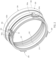
- FIG. 2 a perspective view of the spring biased shroud retention system 200 for coupling the shroud 202 to the engine case 204 is shown.
- the stage of the intermediate pressure turbine 128 is not shown for clarity.
- the shroud 202 is annular and surrounds the stage S2 of the turbine section 108, which in this example is the intermediate pressure turbine 128 ( FIG. 1 ).
- the shroud 202 is composed of any suitable material, such as a metal, metal alloy, composite, polymer-based material, ceramic based material, etc.
- the shroud 202 may be formed by casting, molding, additive manufacturing, machining, etc.
- the shroud 202 is composed of a ceramic based material, which may have a thermal growth rate that is different than a thermal growth rate associated with the engine case 204.
- the shroud 202 is composed of a ceramic matrix composite.
- the shroud 202 includes a first surface 210 opposite a second surface 212.
- the first surface 210 defines an inner diameter of the shroud 202, while the second surface 212 defines an outer diameter of the shroud 202.
- the first surface 210 surrounds a central bore 214 of the shroud 202 ( FIG. 2 ), which is sized to enable the shroud 202 to be positioned about the stage S2 of the turbine section 108 or the intermediate pressure turbine 128 ( FIG.
- the first surface 210 is generally smooth.
- the second surface 212 includes a first flange 216 and a second flange 218. The second surface 212 faces the engine case 204.
- the first flange 216 extends about an entirety of a perimeter or circumference of the second surface 212.
- the first flange 216 cooperates with a first seal 222 and a cover ring 224.
- the first seal 222 seals against the first flange 216 to inhibit the flow of air between the cover ring 224 and the first flange 216.
- the first flange 216 is spaced axially inward from a first end of the shroud 202 to define a lip 225.
- the lip 225 extends about a circumference of the shroud 202, and cooperates with a portion of the cover ring 224.
- the cover ring 224 encloses an end of the shroud 202 proximate the first flange 216, and assists in retaining the first seal 222 against the first flange 216.
- the first flange 216 also includes a plurality of first coupling tabs 226.
- the first flange 216 includes four first coupling tabs 226, which are spaced apart about a circumference of the shroud 202 ( FIG. 2 ).
- first coupling tabs 226 are substantially evenly spaced apart about the circumference of the shroud 202 to assist in coupling the spring biased shroud retention system 200 to the shroud 202 so that the spring biased shroud retention system 200 may maintain concentricity of the shroud 202.
- Each of the first coupling tabs 226 extend radially above a surface of a remainder of the first flange 216 to assist in retaining the spring biased shroud retention system 200 on the shroud 202.
- each of the first coupling tabs 226 includes a first side 228 opposite a second side 230, and a first top surface 232, which interconnects the first side 228 with the second side 230.
- Each of the first side 228, the second side 230 and the first top surface 232 are substantially planar.
- the first side 228 is spaced apart from the second side 230 for a predetermined distance about the circumference of the shroud 202 to provide spacing for a portion of the spring biased shroud retention system 200.
- the first side 228 and the second side 230 are coupled to a portion of the spring biased shroud retention system 200.
- the second flange 218 extends about an entirety of a perimeter or circumference of the second surface 212.
- the second flange 218 is spaced axially inward from a second end of the shroud 202 to define a second lip 234.
- the second end of the shroud 202 is opposite the first end in the axial direction, and the first end is a leading edge of the shroud 202, while the second end is downstream and forms a trailing edge for the shroud 202 in a direction of working fluid flow through the gas turbine engine 100.
- the second lip 234 extends about a circumference of the shroud 202, and cooperates with a portion of the engine case 204.
- the second flange 218 also includes a plurality of second coupling tabs 236.
- the second flange 218 includes four second coupling tabs 236, which are spaced apart about a circumference of the shroud 202 ( FIG. 2 ).
- the second coupling tabs 236 are substantially evenly spaced apart about the circumference of the shroud 202 to assist in coupling the spring biased shroud retention system 200 to the shroud 202 so that the spring biased shroud retention system 200 may maintain concentricity of the shroud 202.
- each of the second coupling tabs 236 extend radially above a surface of a remainder of the second flange 218 to assist in retaining the spring biased shroud retention system 200 on the shroud 202.
- each of the second coupling tabs 236 includes a third side 238 opposite a fourth side 240, and a second top surface 242, which interconnects the third side 238 with the fourth side 240.
- Each of the third side 238, the fourth side 240 and the second top surface 242 are substantially planar.
- the third side 238 is spaced apart from the fourth side 240 for a predetermined distance about the circumference of the shroud 202 to provide spacing for a portion of the spring biased shroud retention system 200.
- the third side 238 and the fourth side 240 are coupled to a portion of the spring biased shroud retention system 200.
- the engine case 204 surrounds the shroud 202 and is fluidly coupled to a source 248 of cooling fluid F.
- the source 248 of cooling fluid F may comprise any suitable source of cooling fluid F associated with the gas turbine engine 100 including, but not limited to, compressed air received from the compressor section 104.
- the engine case 204 is composed of any suitable material, such as a metal, metal alloy, composite, etc.
- the engine case 204 is composed of a metal alloy, which has a thermal growth rate that is different than the thermal growth rate associated with the shroud 202.
- the engine case 204 is composed of a nickel alloy, including, but not limited to Nickel Wasapaloy or Nickel Alloy 718.
- the engine case 204 may be formed by casting, molding, additive manufacturing, machining, etc.
- the engine case 204 includes a first surface 250 opposite a second surface 252 and a first end 253 opposite a second end 254.
- the first end 253 is a leading edge of the engine case 204, while the second end 254 is downstream and forms a trailing edge for the engine case 204 in the direction of working fluid flow through the gas turbine engine 100.
- the first surface 250 defines an inner diameter of the engine case 204, while the second surface 252 defines an outer diameter of the engine case 204.
- the first surface 250 surrounds a central bore 257 of the engine case 204, which is sized to enable the engine case 204 to be positioned about the shroud 202 ( FIG. 2 ).
- the engine case 204 also defines a plurality of mounting pads 256 and a first case cover 258.
- each of the mounting pads 256 are defined on the engine case 204.
- the mounting pads 256 are defined on the second surface 252 of the engine case 204 and proximate or adjacent to the first end 253.
- the mounting pads 256 are raised radially from the second surface 252 of the engine case 204 so as to form a substantially rectangular planar platform for coupling the spring biased shroud retention system 200 to the engine case 204.
- each of the mounting pads 256 includes a first coupling bore 264, a second coupling bore 266, a third coupling bore 268 and a pair of downstream walls 270.
- the first coupling bore 264 is defined through the engine case 204 proximate a first side 256a of the mounting pad 256.
- the first side 256a is opposite a second side 256b.
- the second coupling bore 266 is defined through the engine case 204 proximate a second side 256b of the mounting pad 256.
- the third coupling bore 268 is defined through the engine case 204 between the first coupling bore 264 and the second coupling bore 266.
- the downstream walls 270 extend radially from a downstream end of the mounting pad 256 to define a stop for a portion of the spring biased shroud retention system 200.
- each of the downstream walls 270 includes a triangular extension 272, which extends axially from the respective downstream wall 270.
- the triangular extension 272 acts as a lip, and assists in coupling a portion of the spring biased shroud retention system 200 to the engine case 204.
- the first case cover 258 surrounds a circumference of the engine case 204.
- the first case cover 258 is coupled to the triangular extension 272, and an upstream portion of the first case cover 258 is positioned so as to be underneath the triangular extension 272.
- a portion of the spring biased shroud retention system 200 may contact the first case cover 258.
- the spring biased shroud retention system 200 couples the shroud 202 to the engine case 204 such that axial and radial compliance is retained during thermal growth of the shroud 202 and the engine case 204 while reducing wear on the shroud 202.
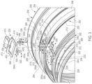
- the spring biased shroud retention system 200 includes at least one load spreader 300, at least one locator pin 302, at least one lock ring 304, a load spreader retainer 306 and a biasing system or spring member 308 ( FIG. 3 ).
- the at least one load spreader 300 includes two load spreaders 300a, 300b
- the at least one locator pin 302 includes two locator pins 302a, 302b
- the at least one lock ring 304 includes two lock rings 304a, 304b.
- each of the load spreaders 300a, 300b includes a first, top spreader surface 310, a second, bottom spreader surface 312 opposite the top spreader surface 310, a plurality of spreader sidewalls 314 and a spreader plenum 316.
- the lock rings 304a, 304b and the spring member 308 are removed for clarity.
- the top spreader surface 310 defines a spreader opening 318.
- the spreader opening 318 is in fluid communication with the spreader plenum 316.
- the spreader opening 318 is sized and shaped to receive the respective locator pin 302a, 302b.
- the bottom spreader surface 312 is in surface-to-surface contact with the second surface 212 of the shroud 202, and inhibits point loading on the shroud 202, which increases a life of the shroud 202.
- the bottom spreader surface 312 also defines a plurality of impingement holes 319.
- the impingement holes 319 direct cooling fluid F received into the spreader plenum 316 to the second surface 212 of the shroud 202.
- each of the load spreaders 300a, 300b is substantially rectangular, and includes four spreader sidewalls 314.
- the spreader sidewalls 314 interconnect the top spreader surface 310 with the bottom spreader surface 312.
- two opposed spreader sidewalls 314a, 314b define a relief 317, which is sized to enable a portion of the spreader sidewalls 314a, 314b to extend over and be received on the respective one of the first flange 216 and the second flange 218.
- Two opposed sidewalls 314c, 314d include a tab 320 that extends from the bottom spreader surface 312 toward the top spreader surface 310.
- the tabs 320 are generally defined to extend from a plane coplanar with a second pin end 326 of the respective locator pin 302a, 302b to the bottom spreader surface 312.
- the tabs 320 extend outwardly from the spreader sidewalls 314c, 314d and increase a volume of the spreader plenum 316.
- the tabs 320 also cooperate with the flanges 216, 218 of the shroud 202 to maintain axial and radial compliance during the thermal growth of the shroud 202 relative to the engine case 204.
- the side of the spreader sidewalls 314c, 314d devoid of the tabs 320 is in contact with a respective one of the first coupling tabs 226 and the second coupling tabs 236.
- the spreader plenum 316 is defined internally within each of the load spreaders 300a, 300b.
- the spreader plenum 316 is defined from the spreader opening 318 to the bottom spreader surface 312.
- the spreader plenum 316 is in fluid communication with the impingement holes 319, and the spreader opening 318. It should be noted that while the load spreaders 300a, 300b are described and illustrated herein as being hollow and including the spreader plenum 316, in other embodiments, the load spreaders 300a, 300b may be solid and devoid of a plenum.
- Each of the locator pins 302a, 302b includes a first pin end 324 opposite a second pin end 326, a pin body 328 that interconnects the first pin end 324 with the second pin end 326 and a central pin bore 330.
- the locator pins 302a, 302b are composed of metal or metal alloy, and may be cast, forged, additively manufactured, etc.
- the first pin end 324 is substantially circular, and includes a plurality of pin teeth 332 about an outer perimeter of the first pin end 324.
- the pin teeth 332 matingly engage with the respective lock ring 304a, 304b to lock or fix the orientation of the locator pin 302a, 302b to the respective load spreader 300a, 300b.
- the first pin end 324 also defines a tool mating feature 334, such as a hex socket, about a perimeter of the central pin bore 330 at the first pin end 324.
- the second pin end 326 is coupled to and received within the spreader opening 318.
- the second pin end 326 defines a spherical contact surface 336 about an outer perimeter of the second pin end 326.
- the spherical contact surface 336 cooperates with the spreader opening 318 to create a ball and socket joint, which enables the locator pin 302a, 302b to move or pivot as needed during the thermal growth of the shroud 202.
- the pin body 328 is substantially cylindrical and includes a first pin body portion 338 and a second pin body portion 340.
- the first pin body portion 338 is defined from the first pin end 324 and extends between the first pin end 324 and the second pin body portion 340.
- the first pin body portion 338 extends along a first axis PA1 ( FIG. 3 ), which is a centerline of the first pin body portion 338.
- the first pin body portion 338 also has a diameter, which is different and greater than a second diameter of the second pin body portion 340.
- the second pin body portion 340 is defined from the first pin body portion 338 and extends between the first pin body portion 338 to the second pin end 326.
- the second pin body portion 340 extends along a second axis PA2 ( FIG. 3 ), which is a centerline of the second pin body portion 340.
- the second axis PA2 is different than the first axis PA1, and is parallel to and offset from the first axis PA1 ( FIG. 3 ).
- the locator pins 302a, 302b act as a cam to accommodate manufacturing tolerances.
- the central pin bore 330 is defined through the pin body 328 from the first pin end 324 to the second pin end 326.
- the central pin bore 330 is defined to extend along the first axis PA1 and the second axis PA2 such that the central pin bore 330 is offset within the pin body 328.
- the central pin bore 330 is in fluid communication with or fluidly coupled to the source 248 of the cooling fluid F ( FIG. 3 ) to receive the fluid F via one or more conduits, plenums, etc.
- the central pin bore 330 is also in fluid communication with the spreader plenum 316 such that when the locator pins 302a, 302b are coupled to the respective load spreader 300a, 300b, the cooling fluid F flows through the central pin bore 330 of the respective locator pins 302a, 302b and into the respective spreader plenum 316. From the spreader plenum 316, the cooling fluid F flows through the impingement holes 319 of the bottom spreader surface 312 to cool the second surface 212 of the shroud 202.
- each of the lock rings 304a, 304b is coupled to the pin teeth 332 of the respective first pin end 324.
- the engine case 204, the load spreader retainer 306 and the spring member 308 are removed for clarity.
- Each of the lock rings 304a, 304b are composed of metal or metal alloy, and may be cast, forged, additively manufactured, etc.
- Each of the lock rings 304a, 304b are substantially square, and include a central lock bore 350. The substantially square shape of the lock rings 304a, 304b cooperates with the downstream walls 270 to form an anti-rotation feature that inhibits the rotation of the lock rings 304a, 304b relative to the load spreaders 300a, 300b.
- the central lock bore 350 includes a plurality of lock teeth 352 about a perimeter or circumference of the central lock bore 350, which matingly engage with the pin teeth 332 of the respective locator pin 302a, 302b.
- each of the locator pins 302a, 302b include about 33 of the pin teeth 332.
- the lock teeth 352 enable the rotational adjustment of the locator pins 302a, 302b, which act as a cam to orientate the load spreaders 300a, 300b on the shroud 202.
- a clockwise rotation of the locator pin 302a, 302b moves the bottom spreader surface 312 into contact with the second surface 212 of the shroud 202.
- a counterclockwise rotation of the locator pin 302a, 302b moves the bottom spreader surface 312 away from contact with the second surface 212 of the shroud 202.
- the load spreader retainer 306 is substantially a rectangular plate, and is substantially flat or planar.
- the load spreader retainer 306 is composed of a metal or metal alloy, and may be cast, forged, stamped, machined, additively manufactured, etc.
- the load spreader retainer 306 includes a first retainer surface 360 opposite a second retainer surface 362, a first retainer end 364 opposite a second retainer end 366, and a retainer bore 368.
- a retainer pin 370 is coupled to the load spreader retainer 306 to transfer the force applied by the spring member 308 to the load spreader retainer 306, which transfers the force to the load spreaders 300a, 300b.
- the first retainer surface 360 is positioned adjacent to the engine case 204 when the spring biased shroud retention system 200 is coupled to the engine case 204.
- the second retainer surface 362 is coupled to and in contact with the top spreader surface 310 of each of the load spreaders 300a, 300b when the spring biased shroud retention system 200 is assembled to the shroud 202 and the engine case 204.
- the first retainer end 364 defines a first cutout 372, which is substantially semicircular.
- the first cutout 372 is sized and shaped to be positioned about a portion of the perimeter of the second pin body portion 340 ( FIG. 5 ) of the locator pin 302a.
- the second retainer end 366 defines a second cutout 374, which is substantially semicircular.
- the second cutout 374 is sized and shaped to be positioned about a portion of the perimeter of the second pin body portion 340 of the locator pin 302b ( FIG. 5 ).
- the retainer bore 368 is defined through the first retainer surface 360 and the second retainer surface 362.
- the retainer bore 368 is generally defined to be centered between the first retainer end 364 and the second retainer end 366.
- the retainer pin 370 couples the load spreader retainer 306 to the engine case 204, and is coupled to the spring member 308.
- the retainer pin 370 is composed of metal or metal alloy, and may be cast, forged, machined, additively manufactured, etc.
- the retainer pin 370 is substantially cylindrical, and has a first retainer pin end 380 opposite a second retainer pin end 382 ( FIG. 5 ). With reference to FIG. 5 , the first retainer pin end 380 is substantially flat or planar, and is coupled to and in contact with a portion of the spring member 308 when the spring member 308 is coupled to the engine case 204.
- the first retainer pin end 380 transfers the force from the spring member 308 to the load spreader retainer 306 such that the second retainer surface 362 applies a force to the load spreaders 300a, 300b to maintain the load spreaders 300a, 300b in contact with the shroud 202.
- the second retainer pin end 382 includes a flange 384.
- the flange 384 has a substantially frustoconical shape and is hollow, with a base of the flange 384 defined at the second retainer pin end 382 and tapering to a vertex 384a that is spaced a distance apart from the second retainer pin end 382.
- the vertex 384a defines a recessed portion about the circumference of the retainer pin 370, which is sized to receive the sidewalls of the retainer bore 368.
- the substantially frustoconical shape of the flange 384 assists in retaining the retainer pin 370 within the retainer bore 368 such that the retainer pin 370 and the load spreader retainer 306 are coupled to the retainer pin 370 to move with the retainer pin 370.
- the spring member 308 is sized and shaped to surround the lock rings 304a, 304b and to bias against the lock rings 304a, 304b to ensure contact between the load spreaders 300a, 300b during the thermal growth of the shroud 202.
- the spring member 308 is a spring clip.
- the spring member 308 is composed of metal or metal alloy, and may be cast, forged, additively manufactured, etc.
- the spring member 308 includes a clip base 390, a clip arm 392 and a biasing member or spring arm 394.
- the clip base 390 and the spring arm 394 define an opening 401.
- the opening 401 is sized to surround the lock rings 304a, 304b, and has a closed perimeter.
- the clip base 390 is substantially U-shaped, and includes a first base arm 396, a second base arm 398 and a third base arm 400.
- the clip base 390 is generally sized and shaped to surround a respective one of the mounting pads 256.
- the first base arm 396, the second base arm 398 and the third base arm 400 are integrally formed in this example.
- Each of the first base arm 396, the second base arm 398 and the third base arm 400 are substantially L-shaped in cross-section, and include a lip 402 that extends radially from each of the first base arm 396, the second base arm 398 and the third base arm 400 proximate the lock rings 304a, 304b.
- the first base arm 396 is opposite the second base arm 398.
- the first base arm 396 is positioned adjacent to the lock ring 304a, while the second base arm 398 is positioned adjacent to the lock ring 304b.
- the first base arm 396 and the second base arm 398 are coupled to the third base arm 400 at one end, and are coupled to the spring arm 394 at an opposite, second end.
- the third base arm 400 interconnects the first base arm 396 and the second base arm 398.
- the clip arm 392 is coupled to the first base arm 396 and the second base arm 398 so as to be spaced apart from the second end of the respective one of the first base arm 396 and the second base arm 398.
- the clip arm 392 extends axially or above the surface of the first base arm 396 and the second base arm 398, and spans the opening 401.
- the clip arm 392 is in contact with the lock rings 304a, 304b when the spring member 308 is coupled to the engine case 204.
- the clip arm 392 provides rigidity to the clip base 390, and also defines a notch 404.
- the notch 404 is defined so as to be centered on the clip arm 392 and aligned with a portion of the spring arm 394.
- the spring arm 394 applies a spring force to the retainer pin 370, which imparts a force to the load spreader retainer 306 during the thermal growth of the shroud 202.
- the spring arm 394 includes a first spring end 410, a second spring end 412 and a biasing or spring portion 414.
- the first spring end 410 is coupled to the first base arm 396 and the second base arm 398 to enclose the opening 401.
- the second spring end 412 is received through the notch 404 defined in the clip arm 392.
- the second spring end 412 has a width, which is different and less than a width of the first spring end 410.
- the second spring end 412 is sized to be positioned between the lock rings 304a, 304b, and to have surface to surface contact with the first retainer pin end 380 of the retainer pin 370.
- the spring portion 414 is curved to interconnect the first spring end 410 with the second spring end 412.
- the spring member 308 is coupled to the engine case 204 with a snap-fit, and the first spring end 410 is forced over the triangular extensions 272.
- the triangular extensions 272 hold the first spring end 410 with the engine case 204 as the second spring end 412 is coupled to the shroud 202 via the load spreader retainer 306.
- the spring portion 414 applies a spring force to the first retainer pin end 380 via the second spring end 412.
- a radial movement of the load spreaders 300a, 300b is inhibited by the spring force applied by the spring portion 414 to the load spreader retainer 306 and further by contact between the spring portion 414 and the notch 404.
- the load spreaders 300a, 300b may be inserted on opposed sides of the first coupling tabs 226 and the second coupling tabs 236 such that the load spreaders 300a, 300b are positioned at about 0 degrees, about 90 degrees, about 180 degrees and about 270 degrees about the circumference of the shroud 202 from a top center of the shroud 202. With the retainer pin 370 coupled to the load spreader retainer 306, the load spreader retainer 306 may be positioned over the load spreaders 300a, 300b.
- the shroud 202 and the load spreaders 300a, 300b may be coupled to the engine case 204 such that the retainer pin 370 is received through the third coupling bore 378.
- the locator pins 302a, 302b are coupled to the respective one of the coupling bores 264, 266 so as to extend through the respective one of the coupling bores 264, 266, through the cutouts 372, 374 and into the respective spreader openings 318.
- the lock rings 304a, 304b are coupled to the locator pins 302a, 302b and rotated to position the respective load spreader 300a, 300b in contact with the second surface 212 of the shroud 202. Once the load spreaders 300a, 300b are in the proper orientation such that surface to surface contact is defined between the bottom spreader surface 312 and the second surface 212, the lock rings 304a, 304b are positioned into contact with the downstream walls 270 such that the downstream walls 270 inhibit the rotation of the lock rings 304a, 304b.
- the spring member 308 is coupled about the lock rings 304a, 304b such that the first spring end 410 is received under the triangular extensions 272 and the second spring end 412 is coupled to or in contact with the first retainer pin end 380.
- the first seal 222 and the cover ring 224 may be coupled to the shroud 202.
- spring biased shroud retention system 200 is described herein as including the spring member 308 to maintain the axial position of the load spreaders 300a, 300b during thermal growth, the spring biased shroud retention system 200 may be configured differently maintain the axial position of the load spreaders 300a, 300b.
- a spring biased shroud retention system 500 is shown. As the spring biased shroud retention system 500 includes components that are the same or similar to components of the spring biased shroud retention system 200 discussed with regard to FIGS. 1-6 , the same reference numerals will be used to denote the same or similar components.
- the spring biased shroud retention system 500 couples the shroud 202 to the engine case 204 such that axial and radial compliance is retained during thermal growth of the shroud 202 and the engine case 204 while reducing wear on the shroud 202.
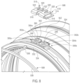
- the spring biased shroud retention system 500 includes the load spreaders 300a, 300b, the locator pins 302a, 302b, the lock rings 304a, 304b, the load spreader retainer 306, a biasing system or a retainer 506 and a spring member 508.
- each of the load spreaders 300a, 300b includes the top spreader surface 310, the bottom spreader surface 312, the plurality of spreader sidewalls 314 and the spreader plenum 316.
- the top spreader surface 310 defines the spreader opening 318.
- the bottom spreader surface 312 is in surface-to-surface contact with the second surface 212 of the shroud 202.
- the bottom spreader surface 312 also defines the plurality of impingement holes 319.
- the spreader sidewalls 314a, 314b define the relief 317, which is sized to enable a portion of the spreader sidewalls 314a, 314b to extend over and be received on the respective one of the first flange 216 and the second flange 218.
- Two opposed sidewalls 314c, 314d include the tab 320 that extends from the bottom spreader surface 312 toward the top spreader surface 310. It should be noted that while the load spreaders 300a, 300b are described and illustrated herein as being hollow and including the spreader plenum 316, in other embodiments, the load spreaders 300a, 300b may be solid and devoid of a plenum.
- each of the locator pins 302a, 302b includes the first pin end 324, the second pin end 326, the pin body 328 and the central pin bore 330.
- the plurality of pin teeth 332 matingly engage with the respective lock ring 304a, 304b to lock or fix the orientation of the locator pin 302a, 302b to the respective load spreader 300a, 300b.
- the first pin end 324 also defines the tool mating feature 334.
- the second pin end 326 is coupled to and received within the spreader opening 318.
- the second pin end 326 defines the spherical contact surface 336 that cooperates with the spreader opening 318 to create the ball and socket joint.
- the pin body 328 includes the first pin body portion 338 and the second pin body portion 340.
- the central pin bore 330 is defined through the pin body 328 and is in fluid communication with or fluidly coupled to the source 248 of the cooling fluid F to receive the fluid F via one or more conduits, plenums, etc.
- the central pin bore 330 is also in fluid communication with the spreader plenum 316.
- Each of the lock rings 304a, 304b is coupled to the pin teeth 332 of the respective first pin end 324.
- Each of the lock rings 304a, 304b include the central lock bore 350.
- the central lock bore 350 includes the plurality of lock teeth 352, which matingly engage with the pin teeth 332 of the respective locator pin 302a, 302b.
- the load spreader retainer 306 includes the first retainer surface 360 opposite the second retainer surface 362, the first retainer end 364 opposite the second retainer end 366, and the retainer bore 368.
- the retainer pin 370 is coupled to the load spreader retainer 306 to transfer the force applied by the spring member 508 to the load spreader retainer 306, which transfers the force to the load spreaders 300a, 300b.
- the first retainer pin end 380 is coupled to and in contact with a portion of the spring member 508 when the spring member 508 is coupled to the engine case 204.
- the first retainer pin end 380 transfers the force from the spring member 508 to the load spreader retainer 306 such that the second retainer surface 362 applies a force to the load spreaders 300a, 300b to maintain the load spreaders 300a, 300b in contact with the shroud 202.
- the second retainer pin end 382 includes the flange 384 that assists in retaining the retainer pin 370 within the retainer bore 368 such that the retainer pin 370 and the load spreader retainer 306 are coupled to the retainer pin 370 to move with the retainer pin 370.
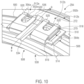
- the retainer 506 includes a base 510 and at least one or a pair of retainer clips 512a, 512b.
- the retainer 506 is composed of a metal or metal alloy, and may be cast, forged, stamped, machined, additively manufactured, etc.
- the base 510 defines a substantially rectangular opening 514, which is sized to be coupled about the lock rings 304a, 304b and the mounting pad 256.
- the retainer 506 is coupled to the engine case 204 with a snap-fit, and the base 510 is forced over the triangular extensions 272.
- Each of the retainer clips 512a, 512b includes a first end 516 coupled to the base 510 and an opposite second end 518.
- the first end 516 is coupled to the base 510 such that each of the retainer clips 512a, 512b is cantilevered over a portion of the opening 514.
- the first end 516 is curved upon itself to form a biasing member or spring, which assists in coupling the retainer 506 to the mounting pad 256.
- the second end 518 defines a pair of arms 520 separated by a slot 522.
- Each of the arms 520 contact a surface of the respective lock rings 304a, 304b, and apply a force to the lock rings 304a, 304b such that the lock rings 304a, 304b apply a force to the load spreaders 300a, 300b to maintain the load spreaders 300a, 300b in contact with the shroud 202.
- the slot 522 enables a tool to engage with the tool mating feature 334 to enable an adjustment of the locator pins 302a, 302b.
- the spring member 508 is annular, and is sized to be positioned about a portion of the engine case 204.
- the spring member 508 is composed of a metal or metal alloy, and may be cast, forged, stamped, machined, additively manufactured, etc.
- the spring member 508 includes a ring 530 and a plurality of coupling arms 532.
- the ring 530 is sized to circumscribe the portion of the engine case 204.
- the coupling arms 532 are coupled to the ring 530 so as to extend axially outward from a side of the ring 530.
- each coupling arm 532 includes a first arm end 534 and an opposite, second arm end 536.
- the second arm end 536 acts as a spring arm.
- the first arm end 534 is coupled to the ring 530 such that the coupling arm 532 is cantilevered relative to the ring 530.
- the second arm end 536 is coupled to the retainer pin 370 or the engine case 204.
- the second arm end 536 applies a spring force to the retainer pin 370, which imparts a force to the load spreader retainer 306 during the thermal growth of the shroud 202.
- the load spreader retainer 306 in turn, imparts a force onto the load spreaders 300a, 300b to maintain contact between the load spreaders 300a, 300b and the shroud 202.
- the second arm end 536 is sized to be positioned between the lock rings 304a, 304b, and to have surface to surface contact with the first retainer pin end 380 of the retainer pin 370.
- a radial movement of the load spreaders 300a, 300b is inhibited by the spring force applied by the second arm end 536 to the load spreader retainer 306.
- the load spreaders 300a, 300b may be inserted on opposed sides of the first coupling tabs 226 and the second coupling tabs 236 such that the load spreaders 300a, 300b are positioned at about 0 degrees, about 90 degrees, about 180 degrees and about 270 degrees about the circumference of the shroud 202 from a top center of the shroud 202. With the retainer pin 370 coupled to the load spreader retainer 306, the load spreader retainer 306 may be positioned over the load spreaders 300a, 300b.
- the shroud 202 and the load spreaders 300a, 300b may be coupled to the engine case 204 such that the retainer pin 370 is received through the third coupling bore 378.
- the locator pins 302a, 302b are coupled to the respective one of the coupling bores 264, 266 so as to extend through the respective one of the coupling bores 264, 266, through the cutouts 372, 374 and into the respective spreader openings 318.
- the lock rings 304a, 304b are coupled to the locator pins 302a, 302b and rotated to position the respective load spreader 300a, 300b in contact with the second surface 212 of the shroud 202.
- the lock rings 304a, 304b are positioned into contact with the downstream walls 270 such that the downstream walls 270 inhibit the rotation of the lock rings 304a, 304b.
- the base 510 is coupled about the mounting pad 256 such that the retainer clips 512a, 512b are in contact with the lock rings 304a, 304b.
- the spring member 508 is coupled to the engine case 204 such that the second arm end 536 is in contact with the retainer pin 370 or the engine case 204.
- the first seal 222 and the cover ring 224 may be coupled to the shroud 202.
- the engine case 204 may be installed in the gas turbine engine 100 and coupled to a combustor case, for example, and the shroud 202 may be positioned about the intermediate pressure turbine 128 ( FIG. 1 ).
- the source 248 of cooling fluid F may be fluidly coupled to the central pin bore 330 of the locator pins 302a, 302b to supply the cooling fluid F to the spreader plenum 316 and the impingement holes 319.
- the spring biased shroud retention system 200, 500 maintains the radial and axial compliance of the shroud 202 as the shroud 202 and engine case 204 thermally grow.
- the spring member 308, 508 maintains the axial position of the load spreaders 300a, 300b during thermal growth by biasing the load spreaders 300a, 300b against the second surface 212 of the shroud 202 via the force applied by the second spring end 412 onto the retainer pin 370 or the second arm end 536 to the retainer pin 370, and thus, the load spreader retainer 306. Stated another way, the spring member 308, 508 inhibits the axial movement of the load spreaders 300a, 300b, which reduceswear on the second surface 212.
- the load spreaders 300a, 300b distribute the axial and the circumferential point load from the locator pins 302a, 302b over the load spreaders 300a, 300b, and thus, the second surface 212 of the shroud 202.
- the load spreaders 300a, 300b distribute the axial and the circumferential point load from the locator pins 302a, 302b over the load spreaders 300a, 300b, and thus, the second surface 212 of the shroud 202.
Landscapes
- Engineering & Computer Science (AREA)
- Mechanical Engineering (AREA)
- General Engineering & Computer Science (AREA)
- Turbine Rotor Nozzle Sealing (AREA)
Abstract
Description
- This invention was made with Government support under 693KA9-21-T-00004 awarded by the Federal Aviation Administration. The Government has certain rights in the invention.
- The present disclosure generally relates to gas turbine engines, and more particularly relates to a spring biased retention system for a shroud associated with a gas turbine engine.
- Compressor or turbine rotor blade stages in gas turbine engines may be provided with shrouds to improve engine performance. In certain instances, the shrouds may thermally expand or grow radially at a different rate than surrounding components. In addition, the components coupling the shroud within the gas turbine engine may thermally expand or grow radially at a different rate than the shroud, which may cause these components to move radially relative to the shroud. The movement of these components relative to the shroud may result in wear on the shroud and may impact a life of the shroud.
- Accordingly, it is desirable to provide a spring biased retention system for coupling a shroud within a gas turbine engine, which reduces radial movement of the components coupling the shroud during the operation of the gas turbine engine. Furthermore, other desirable features and characteristics of the present disclosure will become apparent from the subsequent detailed description and the appended claims, taken in conjunction with the accompanying drawings and the foregoing technical field and background.
- This summary is provided to describe select concepts in a simplified form that are further described in the Detailed Description. This summary is not intended to identify key or essential features of the claimed subject matter, nor is it intended to be used as an aid in determining the scope of the claimed subject matter.
- According to various embodiments, provided is a system for coupling a shroud to a case associated with a gas turbine engine. The system includes the case having a mounting pad, and the shroud having a surface that faces the case. The system includes a load spreader having a spreader surface in contact with the surface of the shroud and a locator pin coupled to the mounting pad and the load spreader to couple the shroud to the case. The system includes a load spreader retainer coupled to the load spreader. The load spreader retainer is configured to distribute a force to the load spreader. The system includes a biasing system coupled about the mounting pad that includes a spring arm configured to apply the force to the load spreader retainer to maintain the spreader surface of the load spreader in contact with the surface of the shroud.
- The shroud defines a first flange and a second flange that extend from the surface of the shroud, the shroud is composed of a ceramic based material and the load spreader is coupled between the first flange and the second flange. The system includes a lock ring coupled to the locator pin, and the mounting pad includes a wall that inhibits a rotation of the lock ring. The biasing system is a biasing member that defines an opening sized to surround the mounting pad, and includes a clip arm that spans the opening and contacts the lock ring. The clip arm includes a notch configured to receive a portion of the spring arm. The mounting pad includes a wall that has an extension that extends axially from the wall, and the biasing system is coupled about the mounting pad so as to be at least partially retained by the extension. The load spreader is hollow and defines a plenum. The locator pin defines a central cooling bore that is in fluid communication with the plenum and is configured to be coupled to a source of a cooling fluid. The spreader surface defines a plurality of impingement holes configured to direct the cooling fluid onto the surface of the shroud. A retainer pin couples the load spreader retainer to the mounting pad, and the spring arm is configured to apply the force to an end of the retainer pin. The biasing system includes a retainer and an annular biasing member, the retainer is coupled to the lock ring and the annular biasing member includes the spring arm.
- Also provided is a gas turbine engine. The gas turbine engine includes a case having a mounting pad, and a shroud having a surface. The gas turbine engine includes a first load spreader having a first spreader surface in contact with the surface of the shroud, and a second load spreader having a second spreader surface in contact with the surface of the shroud. The second load spreader is spaced apart from the first load spreader on the surface of the shroud. The gas turbine engine includes a first locator pin coupled to the mounting pad and the first load spreader to couple the shroud to the case, and a second locator pin coupled to the mounting pad and the second load spreader to couple the shroud to the case. The gas turbine engine includes a load spreader retainer coupled to the first load spreader and the second load spreader. The load spreader retainer is configured to distribute a force to the first load spreader and the second load spreader. The gas turbine engine includes a biasing system coupled about the mounting pad that includes a spring arm configured to apply the force to the load spreader retainer to maintain the first spreader surface of the first load spreader and the second spreader surface of the second load spreader in contact with the surface of the shroud.
- The shroud defines a first flange and a second flange that extend from the surface of the shroud, the shroud is composed of a ceramic based material and the first load spreader and the second load spreader are coupled between the first flange and the second flange. The gas turbine engine includes a first lock ring coupled to the first locator pin, a second lock ring coupled to the second locator pin, and the mounting pad includes a pair of walls that inhibit a rotation of the first lock ring and the second lock ring. Each wall of the pair of walls includes an extension that extends axially, and the biasing system is coupled about the mounting pad so as to be at least partially retained by the extension. The biasing system is a biasing member that defines an opening sized to surround the mounting pad, includes a clip arm that spans the opening and contacts the first lock ring and the second lock ring, and the clip arm defines a notch configured to receive a portion of the spring arm.
- Further provided is a gas turbine engine. The gas turbine engine includes a case having a mounting pad, and a shroud having a surface. The gas turbine engine includes a load spreader having a spreader surface in contact with the surface of the shroud, and the load spreader is hollow and defines a plenum. The gas turbine engine includes a locator pin coupled to the mounting pad and the load spreader to couple the shroud to the case. The locator pin defines a central cooling bore that is in fluid communication with the plenum and is configured to be coupled to a source of a cooling fluid. The spreader surface defines a plurality of impingement holes configured to direct the cooling fluid onto the surface of the shroud.
- The gas turbine engine includes a load spreader retainer coupled to the load spreader, the load spreader retainer configured to distribute a force to the load spreader, and a biasing system coupled about the mounting pad that includes a spring arm configured to apply the force to the load spreader retainer to maintain the spreader surface of the load spreader in contact with the surface of the shroud. The shroud defines a first flange and a second flange that extend from the surface of the shroud, the shroud is composed of a ceramic based material and the load spreader is coupled between the first flange and the second flange. The gas turbine engine includes a lock ring coupled to the locator pin, and the mounting pad includes a wall that inhibits a rotation of the lock ring.
- The present disclosure will hereinafter be described in conjunction with the following drawing figures, wherein like numerals denote like elements, and wherein:
-
FIG. 1 is a schematic cross-sectional illustration of a gas turbine engine, which includes an exemplary spring biased retention system in accordance with the various teachings of the present disclosure; -
FIG. 2 is a perspective view of the spring biased retention system coupling a shroud to an engine case in accordance with various embodiments; -
FIG. 2A is a detail view of the spring biased retention system ofFIG. 2 , taken at 2A onFIG. 2 ; -
FIG. 3 is a partially exploded view of the spring biased retention system, the shroud and the engine case; -
FIG. 3A is an exploded view of a portion of the spring biased retention system from the shroud; -
FIG. 4 is a cross-sectional view of the spring biased retention system, the shroud and the engine case taken along line 4-4 ofFIG. 2A ; -
FIG. 5 is a cross-sectional view of the spring biased retention system, the shroud and the engine case taken along line 5-5 ofFIG. 2A , in which the lock rings have been removed for clarity; -
FIG. 6 is a detail view of a portion of the spring biased retention system coupled to the shroud; -
FIG. 7 is a perspective view of another exemplary spring biased retention system for coupling the shroud to the engine case in accordance with various embodiments; -
FIG. 8 is a partially exploded view of the spring biased retention system, the shroud and the engine case ofFIG. 7 ; -
FIG. 9 is a cross-sectional view of the spring biased retention system, the shroud and the engine case taken along line 9-9 ofFIG. 10 ; and -
FIG. 10 is a detail view of the spring biased retention system ofFIG. 7 . - The following detailed description is merely exemplary in nature and is not intended to limit the application and uses. Furthermore, there is no intention to be bound by any expressed or implied theory presented in the preceding technical field, background, brief summary or the following detailed description. In addition, those skilled in the art will appreciate that embodiments of the present disclosure may be practiced in conjunction with any type of arrangement that would benefit from a spring biased retention system and the use of the spring biased retention system for coupling a shroud to a case associated with a gas turbine engine described herein is merely one exemplary embodiment according to the present disclosure. In addition, while the spring biased retention system is described herein as being used with a gas turbine engine onboard a mobile platform, such as a bus, motorcycle, train, motor vehicle, marine vessel, aircraft, rotorcraft and the like, the various teachings of the present disclosure can be used with a gas turbine engine on a stationary platform. Further, it should be noted that many alternative or additional functional relationships or physical connections may be present in an embodiment of the present disclosure. In addition, while the figures shown herein depict an example with certain arrangements of elements, additional intervening elements, devices, features, or components may be present in an actual embodiment. It should also be understood that the drawings are merely illustrative and may not be drawn to scale.
- As used herein, the term "axial" refers to a direction that is generally parallel to or coincident with an axis of rotation, axis of symmetry, or centerline of a component or components. For example, in a cylinder or disc with a centerline and generally circular ends or opposing faces, the "axial" direction may refer to the direction that generally extends in parallel to the centerline between the opposite ends or faces. In certain instances, the term "axial" may be utilized with respect to components that are not cylindrical (or otherwise radially symmetric). For example, the "axial" direction for a rectangular housing containing a rotating shaft may be viewed as a direction that is generally parallel to or coincident with the rotational axis of the shaft. Furthermore, the term "radially" as used herein may refer to a direction or a relationship of components with respect to a line extending outward from a shared centerline, axis, or similar reference, for example in a plane of a cylinder or disc that is perpendicular to the centerline or axis. In certain instances, components may be viewed as "radially" aligned even though one or both of the components may not be cylindrical (or otherwise radially symmetric). Furthermore, the terms "axial" and "radial" (and any derivatives) may encompass directional relationships that are other than precisely aligned with (e.g., oblique to) the true axial and radial dimensions, provided the relationship is predominantly in the respective nominal axial or radial direction. As used herein, the term "about" denotes within 10% to account for manufacturing tolerances. In addition, the term "substantially" denotes within 10% to account for manufacturing tolerances.
- With reference to
FIG. 1 , a partial, cross-sectional view of an exemplarygas turbine engine 100 is shown with the remaining portion of thegas turbine engine 100 being substantially axisymmetric about alongitudinal axis 140, which also comprises an axis of rotation for thegas turbine engine 100. In the depicted embodiment, thegas turbine engine 100 is an annular multi-spool turbofan gas turbine jet engine within anaircraft 99, although other arrangements and uses may be provided. As will be discussed herein, with brief reference toFIGS. 2 and2A , thegas turbine engine 100 includes a spring biasedshroud retention system 200 for coupling ashroud 202 to a casing orengine case 204. In one example, the spring biasedshroud retention system 200, theshroud 202 and theengine case 204 are associated with a stage S2 of aturbine section 108 of the gas turbine engine 100 (FIG. 1 ), however, the spring biasedshroud retention system 200, theshroud 202 and theengine case 204 may be associated with other stages of theturbine section 108 and/or a stage of acompressor section 104 of thegas turbine engine 100. As will be discussed, the spring biasedshroud retention system 200 maintains the axial and circumferential alignment of theshroud 202 or concentricity of theshroud 202 relative to theengine case 204 even with differences in thermal growth between theshroud 202 and theengine case 204. In addition, the spring biasedshroud retention system 200 also ensures that the spring biasedshroud retention system 200 remains coupled to theshroud 202 during thermal growth of theshroud 202 and substantially inhibits radial movement of the spring biasedshroud retention system 200 relative to theshroud 202 during thermal growth, which reduces wear on theshroud 202. - In this example, with reference back to
FIG. 1 , thegas turbine engine 100 includes afan section 102, thecompressor section 104, acombustor section 106, theturbine section 108, and anexhaust section 110. Thefan section 102 includes afan 112 mounted on arotor 114 that draws air into thegas turbine engine 100 and accelerates it. A fraction of the accelerated air exhausted from thefan 112 is directed through an outer (or first)bypass duct 116 and the remaining fraction of air exhausted from thefan 112 is directed into thecompressor section 104. Theouter bypass duct 116 is generally defined between theinner bypass duct 118 and anouter casing 144. In the embodiment ofFIG. 1 , thecompressor section 104 includes anintermediate pressure compressor 120 and a high-pressure compressor 122. However, in other embodiments, the number of compressors in thecompressor section 104 may vary. In the depicted embodiment, theintermediate pressure compressor 120 and the high-pressure compressor 122 sequentially raise the pressure of the air and direct a majority of the high-pressure air into thecombustor section 106. A fraction of the compressed air bypasses thecombustor section 106 and is used to cool, among other components, turbine blades in theturbine section 108. - In the embodiment of
FIG. 1 , in thecombustor section 106, which includes acombustion chamber 124, the high-pressure air is mixed with fuel, which is combusted. The high-temperature combustion air is directed into theturbine section 108. In this example, theturbine section 108 includes three turbines disposed in axial flow series, namely, a high-pressure turbine 126, anintermediate pressure turbine 128, and a low-pressure turbine 130. However, it will be appreciated that the number of turbines, and/or the configurations thereof, may vary. In this embodiment, the high-temperature air from thecombustor section 106 expands through and rotates eachturbine turbines gas turbine engine 100 via concentrically disposed shafts or spools. In one example, the high-pressure turbine 126 drives the high-pressure compressor 122 via a high-pressure shaft 134, theintermediate pressure turbine 128 drives theintermediate pressure compressor 120 via anintermediate pressure shaft 136, and the low-pressure turbine 130 drives thefan 112 via a low-pressure shaft 138. In this example, theshroud 202 is circumferentially disposed about theintermediate pressure turbine 128, and theengine case 204 is coupled to a portion of a casing associated with thecombustor section 106. The spring biasedshroud retention system 200 couples theshroud 202 to theengine case 204. The casing associated with thecombustor section 106, in turn, may be coupled to theinner bypass duct 118. It should be noted that the placement of theshroud 202 and theengine case 204 about theintermediate pressure turbine 128 is merely exemplary, as theshroud 202, theengine case 204 and the spring biasedshroud retention system 200 may be employed with any turbine in theturbine section 108 or compressor in thecompressor section 104. - With reference to
FIG. 2 , a perspective view of the spring biasedshroud retention system 200 for coupling theshroud 202 to theengine case 204 is shown. InFIG. 2 , the stage of theintermediate pressure turbine 128 is not shown for clarity. In one example, theshroud 202 is annular and surrounds the stage S2 of theturbine section 108, which in this example is the intermediate pressure turbine 128 (FIG. 1 ). Theshroud 202 is composed of any suitable material, such as a metal, metal alloy, composite, polymer-based material, ceramic based material, etc. Theshroud 202 may be formed by casting, molding, additive manufacturing, machining, etc. In one example, theshroud 202 is composed of a ceramic based material, which may have a thermal growth rate that is different than a thermal growth rate associated with theengine case 204. For example, theshroud 202 is composed of a ceramic matrix composite. With reference toFIG. 3 , theshroud 202 includes afirst surface 210 opposite asecond surface 212. Thefirst surface 210 defines an inner diameter of theshroud 202, while thesecond surface 212 defines an outer diameter of theshroud 202. Thefirst surface 210 surrounds acentral bore 214 of the shroud 202 (FIG. 2 ), which is sized to enable theshroud 202 to be positioned about the stage S2 of theturbine section 108 or the intermediate pressure turbine 128 (FIG. 1 ) at a predefined distance from the rotor blades associated with theintermediate pressure turbine 128. Thefirst surface 210 is generally smooth. Thesecond surface 212 includes afirst flange 216 and asecond flange 218. Thesecond surface 212 faces theengine case 204. - The
first flange 216 extends about an entirety of a perimeter or circumference of thesecond surface 212. Thefirst flange 216 cooperates with afirst seal 222 and acover ring 224. Thefirst seal 222 seals against thefirst flange 216 to inhibit the flow of air between thecover ring 224 and thefirst flange 216. In one example, thefirst flange 216 is spaced axially inward from a first end of theshroud 202 to define alip 225. Thelip 225 extends about a circumference of theshroud 202, and cooperates with a portion of thecover ring 224. Thecover ring 224 encloses an end of theshroud 202 proximate thefirst flange 216, and assists in retaining thefirst seal 222 against thefirst flange 216. In one example, thefirst flange 216 also includes a plurality offirst coupling tabs 226. In this example, thefirst flange 216 includes fourfirst coupling tabs 226, which are spaced apart about a circumference of the shroud 202 (FIG. 2 ). Generally, thefirst coupling tabs 226 are substantially evenly spaced apart about the circumference of theshroud 202 to assist in coupling the spring biasedshroud retention system 200 to theshroud 202 so that the spring biasedshroud retention system 200 may maintain concentricity of theshroud 202. Each of thefirst coupling tabs 226 extend radially above a surface of a remainder of thefirst flange 216 to assist in retaining the spring biasedshroud retention system 200 on theshroud 202. In one example, each of thefirst coupling tabs 226 includes afirst side 228 opposite a second side 230, and a firsttop surface 232, which interconnects thefirst side 228 with the second side 230. Each of thefirst side 228, the second side 230 and the firsttop surface 232 are substantially planar. Thefirst side 228 is spaced apart from the second side 230 for a predetermined distance about the circumference of theshroud 202 to provide spacing for a portion of the spring biasedshroud retention system 200. Thefirst side 228 and the second side 230 are coupled to a portion of the spring biasedshroud retention system 200. - The
second flange 218 extends about an entirety of a perimeter or circumference of thesecond surface 212. In one example, thesecond flange 218 is spaced axially inward from a second end of theshroud 202 to define asecond lip 234. The second end of theshroud 202 is opposite the first end in the axial direction, and the first end is a leading edge of theshroud 202, while the second end is downstream and forms a trailing edge for theshroud 202 in a direction of working fluid flow through thegas turbine engine 100. Thesecond lip 234 extends about a circumference of theshroud 202, and cooperates with a portion of theengine case 204. In one example, thesecond flange 218 also includes a plurality ofsecond coupling tabs 236. In this example, thesecond flange 218 includes foursecond coupling tabs 236, which are spaced apart about a circumference of the shroud 202 (FIG. 2 ). Generally, thesecond coupling tabs 236 are substantially evenly spaced apart about the circumference of theshroud 202 to assist in coupling the spring biasedshroud retention system 200 to theshroud 202 so that the spring biasedshroud retention system 200 may maintain concentricity of theshroud 202. Each of thesecond coupling tabs 236 extend radially above a surface of a remainder of thesecond flange 218 to assist in retaining the spring biasedshroud retention system 200 on theshroud 202. In one example, each of thesecond coupling tabs 236 includes athird side 238 opposite afourth side 240, and a secondtop surface 242, which interconnects thethird side 238 with thefourth side 240. Each of thethird side 238, thefourth side 240 and the secondtop surface 242 are substantially planar. Thethird side 238 is spaced apart from thefourth side 240 for a predetermined distance about the circumference of theshroud 202 to provide spacing for a portion of the spring biasedshroud retention system 200. Thethird side 238 and thefourth side 240 are coupled to a portion of the spring biasedshroud retention system 200. - The
engine case 204 surrounds theshroud 202 and is fluidly coupled to asource 248 of cooling fluid F. Thesource 248 of cooling fluid F may comprise any suitable source of cooling fluid F associated with thegas turbine engine 100 including, but not limited to, compressed air received from thecompressor section 104. Theengine case 204 is composed of any suitable material, such as a metal, metal alloy, composite, etc. In one example, theengine case 204 is composed of a metal alloy, which has a thermal growth rate that is different than the thermal growth rate associated with theshroud 202. For example, theengine case 204 is composed of a nickel alloy, including, but not limited to Nickel Wasapaloy or Nickel Alloy 718. Theengine case 204 may be formed by casting, molding, additive manufacturing, machining, etc. Theengine case 204 includes afirst surface 250 opposite asecond surface 252 and afirst end 253 opposite asecond end 254. Thefirst end 253 is a leading edge of theengine case 204, while thesecond end 254 is downstream and forms a trailing edge for theengine case 204 in the direction of working fluid flow through thegas turbine engine 100. Thefirst surface 250 defines an inner diameter of theengine case 204, while thesecond surface 252 defines an outer diameter of theengine case 204. Thefirst surface 250 surrounds acentral bore 257 of theengine case 204, which is sized to enable theengine case 204 to be positioned about the shroud 202 (FIG. 2 ). Theengine case 204 also defines a plurality of mounting pads 256 and afirst case cover 258. - With continued reference to
FIG. 3 , each of the mounting pads 256 are defined on theengine case 204. The mounting pads 256 are defined on thesecond surface 252 of theengine case 204 and proximate or adjacent to thefirst end 253. In one example, the mounting pads 256 are raised radially from thesecond surface 252 of theengine case 204 so as to form a substantially rectangular planar platform for coupling the spring biasedshroud retention system 200 to theengine case 204. Thus, generally, there is a respective one of the mounting pads 256 for each one of the spring biasedshroud retention systems 200 associated with theshroud 202 andengine case 204. In one example, each of the mounting pads 256 includes afirst coupling bore 264, a second coupling bore 266, a third coupling bore 268 and a pair ofdownstream walls 270. - The first coupling bore 264 is defined through the
engine case 204 proximate afirst side 256a of the mounting pad 256. Thefirst side 256a is opposite asecond side 256b. The second coupling bore 266 is defined through theengine case 204 proximate asecond side 256b of the mounting pad 256. The third coupling bore 268 is defined through theengine case 204 between thefirst coupling bore 264 and thesecond coupling bore 266. In this example, thedownstream walls 270 extend radially from a downstream end of the mounting pad 256 to define a stop for a portion of the spring biasedshroud retention system 200. Thedownstream walls 270 are spaced apart from each other in the circumferential direction to enable a portion of the spring biasedshroud retention system 200 to be positioned between thedownstream walls 270. In one example, each of thedownstream walls 270 includes atriangular extension 272, which extends axially from the respectivedownstream wall 270. Thetriangular extension 272 acts as a lip, and assists in coupling a portion of the spring biasedshroud retention system 200 to theengine case 204. - The
first case cover 258 surrounds a circumference of theengine case 204. Thefirst case cover 258 is coupled to thetriangular extension 272, and an upstream portion of thefirst case cover 258 is positioned so as to be underneath thetriangular extension 272. A portion of the spring biasedshroud retention system 200 may contact thefirst case cover 258. - The spring biased
shroud retention system 200 couples theshroud 202 to theengine case 204 such that axial and radial compliance is retained during thermal growth of theshroud 202 and theengine case 204 while reducing wear on theshroud 202. In one example, with reference toFIGS. 3 and3A , the spring biasedshroud retention system 200 includes at least oneload spreader 300, at least onelocator pin 302, at least onelock ring 304, aload spreader retainer 306 and a biasing system or spring member 308 (FIG. 3 ). - In this example, the at least one
load spreader 300 includes twoload spreaders locator pin 302 includes twolocator pins lock ring 304 includes twolock rings FIG. 5 , each of theload spreaders top spreader surface 310, a second,bottom spreader surface 312 opposite thetop spreader surface 310, a plurality ofspreader sidewalls 314 and aspreader plenum 316. InFIG. 5 , the lock rings 304a, 304b and thespring member 308 are removed for clarity. Thetop spreader surface 310 defines aspreader opening 318. Thespreader opening 318 is in fluid communication with thespreader plenum 316. Thespreader opening 318 is sized and shaped to receive therespective locator pin bottom spreader surface 312 is in surface-to-surface contact with thesecond surface 212 of theshroud 202, and inhibits point loading on theshroud 202, which increases a life of theshroud 202. Thebottom spreader surface 312 also defines a plurality of impingement holes 319. The impingement holes 319 direct cooling fluid F received into thespreader plenum 316 to thesecond surface 212 of theshroud 202. In this example, each of theload spreaders spreader sidewalls 314. The spreader sidewalls 314 interconnect thetop spreader surface 310 with thebottom spreader surface 312. With reference toFIG. 3A , two opposed spreader sidewalls 314a, 314b define arelief 317, which is sized to enable a portion of the spreader sidewalls 314a, 314b to extend over and be received on the respective one of thefirst flange 216 and thesecond flange 218. Twoopposed sidewalls tab 320 that extends from thebottom spreader surface 312 toward thetop spreader surface 310. Thetabs 320 are generally defined to extend from a plane coplanar with asecond pin end 326 of therespective locator pin bottom spreader surface 312. Thetabs 320 extend outwardly from thespreader sidewalls spreader plenum 316. Thetabs 320 also cooperate with theflanges shroud 202 to maintain axial and radial compliance during the thermal growth of theshroud 202 relative to theengine case 204. The side of thespreader sidewalls tabs 320 is in contact with a respective one of thefirst coupling tabs 226 and thesecond coupling tabs 236. Thespreader plenum 316 is defined internally within each of theload spreaders spreader plenum 316 is defined from thespreader opening 318 to thebottom spreader surface 312. Thespreader plenum 316 is in fluid communication with the impingement holes 319, and thespreader opening 318. It should be noted that while theload spreaders spreader plenum 316, in other embodiments, theload spreaders - Each of the
locator pins first pin end 324 opposite asecond pin end 326, apin body 328 that interconnects thefirst pin end 324 with thesecond pin end 326 and a central pin bore 330. The locator pins 302a, 302b are composed of metal or metal alloy, and may be cast, forged, additively manufactured, etc. Thefirst pin end 324 is substantially circular, and includes a plurality ofpin teeth 332 about an outer perimeter of thefirst pin end 324. Thepin teeth 332 matingly engage with therespective lock ring locator pin respective load spreader first pin end 324 also defines atool mating feature 334, such as a hex socket, about a perimeter of the central pin bore 330 at thefirst pin end 324. - The
second pin end 326 is coupled to and received within thespreader opening 318. Thesecond pin end 326 defines aspherical contact surface 336 about an outer perimeter of thesecond pin end 326. Thespherical contact surface 336 cooperates with thespreader opening 318 to create a ball and socket joint, which enables thelocator pin shroud 202. Thepin body 328 is substantially cylindrical and includes a firstpin body portion 338 and a secondpin body portion 340. The firstpin body portion 338 is defined from thefirst pin end 324 and extends between thefirst pin end 324 and the secondpin body portion 340. The firstpin body portion 338 extends along a first axis PA1 (FIG. 3 ), which is a centerline of the firstpin body portion 338. The firstpin body portion 338 also has a diameter, which is different and greater than a second diameter of the secondpin body portion 340. The secondpin body portion 340 is defined from the firstpin body portion 338 and extends between the firstpin body portion 338 to thesecond pin end 326. The secondpin body portion 340 extends along a second axis PA2 (FIG. 3 ), which is a centerline of the secondpin body portion 340. The second axis PA2 is different than the first axis PA1, and is parallel to and offset from the first axis PA1 (FIG. 3 ). By providing the firstpin body portion 338 with a centerline (first axis PA1) that is offset from the centerline of the second pin body portion 340 (second axis PA2), thelocator pins - The central pin bore 330 is defined through the
pin body 328 from thefirst pin end 324 to thesecond pin end 326. The central pin bore 330 is defined to extend along the first axis PA1 and the second axis PA2 such that the central pin bore 330 is offset within thepin body 328. The central pin bore 330 is in fluid communication with or fluidly coupled to thesource 248 of the cooling fluid F (FIG. 3 ) to receive the fluid F via one or more conduits, plenums, etc. The central pin bore 330 is also in fluid communication with thespreader plenum 316 such that when thelocator pins respective load spreader respective locator pins respective spreader plenum 316. From thespreader plenum 316, the cooling fluid F flows through the impingement holes 319 of thebottom spreader surface 312 to cool thesecond surface 212 of theshroud 202. - With reference to
FIG. 6 , each of the lock rings 304a, 304b is coupled to thepin teeth 332 of the respectivefirst pin end 324. InFIG. 6 , theengine case 204, theload spreader retainer 306 and thespring member 308 are removed for clarity. Each of the lock rings 304a, 304b are composed of metal or metal alloy, and may be cast, forged, additively manufactured, etc. Each of the lock rings 304a, 304b are substantially square, and include a central lock bore 350. The substantially square shape of the lock rings 304a, 304b cooperates with thedownstream walls 270 to form an anti-rotation feature that inhibits the rotation of the lock rings 304a, 304b relative to theload spreaders lock teeth 352 about a perimeter or circumference of the central lock bore 350, which matingly engage with thepin teeth 332 of therespective locator pin locator pins pin teeth 332. Thelock teeth 352 enable the rotational adjustment of thelocator pins load spreaders shroud 202. In one example, a clockwise rotation of thelocator pin bottom spreader surface 312 into contact with thesecond surface 212 of theshroud 202. A counterclockwise rotation of thelocator pin bottom spreader surface 312 away from contact with thesecond surface 212 of theshroud 202. In this example, correspondingnotches first pin end 324 of thelocator pin lock ring - With reference to
FIG. 3 , theload spreader retainer 306 is substantially a rectangular plate, and is substantially flat or planar. Theload spreader retainer 306 is composed of a metal or metal alloy, and may be cast, forged, stamped, machined, additively manufactured, etc. Theload spreader retainer 306 includes afirst retainer surface 360 opposite asecond retainer surface 362, a first retainer end 364 opposite asecond retainer end 366, and aretainer bore 368. Aretainer pin 370 is coupled to theload spreader retainer 306 to transfer the force applied by thespring member 308 to theload spreader retainer 306, which transfers the force to theload spreaders - The
first retainer surface 360 is positioned adjacent to theengine case 204 when the spring biasedshroud retention system 200 is coupled to theengine case 204. Thesecond retainer surface 362 is coupled to and in contact with thetop spreader surface 310 of each of theload spreaders shroud retention system 200 is assembled to theshroud 202 and theengine case 204. The first retainer end 364 defines afirst cutout 372, which is substantially semicircular. Thefirst cutout 372 is sized and shaped to be positioned about a portion of the perimeter of the second pin body portion 340 (FIG. 5 ) of thelocator pin 302a. Thesecond retainer end 366 defines asecond cutout 374, which is substantially semicircular. Thesecond cutout 374 is sized and shaped to be positioned about a portion of the perimeter of the secondpin body portion 340 of thelocator pin 302b (FIG. 5 ). The retainer bore 368 is defined through thefirst retainer surface 360 and thesecond retainer surface 362. The retainer bore 368 is generally defined to be centered between the first retainer end 364 and thesecond retainer end 366. - The
retainer pin 370 couples theload spreader retainer 306 to theengine case 204, and is coupled to thespring member 308. Theretainer pin 370 is composed of metal or metal alloy, and may be cast, forged, machined, additively manufactured, etc. Theretainer pin 370 is substantially cylindrical, and has a firstretainer pin end 380 opposite a second retainer pin end 382 (FIG. 5 ). With reference toFIG. 5 , the firstretainer pin end 380 is substantially flat or planar, and is coupled to and in contact with a portion of thespring member 308 when thespring member 308 is coupled to theengine case 204. The firstretainer pin end 380 transfers the force from thespring member 308 to theload spreader retainer 306 such that thesecond retainer surface 362 applies a force to theload spreaders load spreaders shroud 202. The secondretainer pin end 382 includes aflange 384. In one example, theflange 384 has a substantially frustoconical shape and is hollow, with a base of theflange 384 defined at the secondretainer pin end 382 and tapering to avertex 384a that is spaced a distance apart from the secondretainer pin end 382. Thevertex 384a defines a recessed portion about the circumference of theretainer pin 370, which is sized to receive the sidewalls of theretainer bore 368. The substantially frustoconical shape of theflange 384 assists in retaining theretainer pin 370 within the retainer bore 368 such that theretainer pin 370 and theload spreader retainer 306 are coupled to theretainer pin 370 to move with theretainer pin 370. - With reference to
FIG. 2A , thespring member 308 is sized and shaped to surround the lock rings 304a, 304b and to bias against the lock rings 304a, 304b to ensure contact between theload spreaders shroud 202. In one example, thespring member 308 is a spring clip. Thespring member 308 is composed of metal or metal alloy, and may be cast, forged, additively manufactured, etc. With reference toFIG. 3 , thespring member 308 includes aclip base 390, aclip arm 392 and a biasing member orspring arm 394. Theclip base 390 and thespring arm 394 define anopening 401. Theopening 401 is sized to surround the lock rings 304a, 304b, and has a closed perimeter. - The
clip base 390 is substantially U-shaped, and includes afirst base arm 396, asecond base arm 398 and athird base arm 400. Theclip base 390 is generally sized and shaped to surround a respective one of the mounting pads 256. Thefirst base arm 396, thesecond base arm 398 and thethird base arm 400 are integrally formed in this example. Each of thefirst base arm 396, thesecond base arm 398 and thethird base arm 400 are substantially L-shaped in cross-section, and include alip 402 that extends radially from each of thefirst base arm 396, thesecond base arm 398 and thethird base arm 400 proximate the lock rings 304a, 304b. Thefirst base arm 396 is opposite thesecond base arm 398. Thefirst base arm 396 is positioned adjacent to thelock ring 304a, while thesecond base arm 398 is positioned adjacent to thelock ring 304b. Thefirst base arm 396 and thesecond base arm 398 are coupled to thethird base arm 400 at one end, and are coupled to thespring arm 394 at an opposite, second end. Thethird base arm 400 interconnects thefirst base arm 396 and thesecond base arm 398. - The
clip arm 392 is coupled to thefirst base arm 396 and thesecond base arm 398 so as to be spaced apart from the second end of the respective one of thefirst base arm 396 and thesecond base arm 398. Theclip arm 392 extends axially or above the surface of thefirst base arm 396 and thesecond base arm 398, and spans theopening 401. Theclip arm 392 is in contact with the lock rings 304a, 304b when thespring member 308 is coupled to theengine case 204. Theclip arm 392 provides rigidity to theclip base 390, and also defines a notch 404. The notch 404 is defined so as to be centered on theclip arm 392 and aligned with a portion of thespring arm 394. - The
spring arm 394 applies a spring force to theretainer pin 370, which imparts a force to theload spreader retainer 306 during the thermal growth of theshroud 202. Theload spreader retainer 306, in turn, imparts a force onto theload spreaders load spreaders shroud 202. In one example, thespring arm 394 includes afirst spring end 410, asecond spring end 412 and a biasing orspring portion 414. Thefirst spring end 410 is coupled to thefirst base arm 396 and thesecond base arm 398 to enclose theopening 401. Thesecond spring end 412 is received through the notch 404 defined in theclip arm 392. Thesecond spring end 412 has a width, which is different and less than a width of thefirst spring end 410. Generally, with reference toFIG. 4 , thesecond spring end 412 is sized to be positioned between the lock rings 304a, 304b, and to have surface to surface contact with the firstretainer pin end 380 of theretainer pin 370. Thespring portion 414 is curved to interconnect thefirst spring end 410 with thesecond spring end 412. Generally, thespring member 308 is coupled to theengine case 204 with a snap-fit, and thefirst spring end 410 is forced over thetriangular extensions 272. Thetriangular extensions 272 hold thefirst spring end 410 with theengine case 204 as thesecond spring end 412 is coupled to theshroud 202 via theload spreader retainer 306. Thespring portion 414 applies a spring force to the firstretainer pin end 380 via thesecond spring end 412. A radial movement of theload spreaders spring portion 414 to theload spreader retainer 306 and further by contact between thespring portion 414 and the notch 404. By inhibiting the radial movement of theload spreaders second surface 212 of theshroud 202 is reduced. - In order to couple the
shroud 202 to theengine case 204, in one example, with reference toFIGS. 3 and5 , theload spreaders first coupling tabs 226 and thesecond coupling tabs 236 such that theload spreaders shroud 202 from a top center of theshroud 202. With theretainer pin 370 coupled to theload spreader retainer 306, theload spreader retainer 306 may be positioned over theload spreaders spreader openings 318 coaxially aligned with the respective one of the coupling bores 264, 266, and theretainer pin 370 coaxially aligned with the third coupling bore 268, theshroud 202 and theload spreaders engine case 204 such that theretainer pin 370 is received through the third coupling bore 378. The locator pins 302a, 302b, are coupled to the respective one of the coupling bores 264, 266 so as to extend through the respective one of the coupling bores 264, 266, through thecutouts respective spreader openings 318. The lock rings 304a, 304b are coupled to thelocator pins respective load spreader second surface 212 of theshroud 202. Once theload spreaders bottom spreader surface 312 and thesecond surface 212, the lock rings 304a, 304b are positioned into contact with thedownstream walls 270 such that thedownstream walls 270 inhibit the rotation of the lock rings 304a, 304b. With thefirst case cover 258 coupled to theengine case 204, thespring member 308 is coupled about the lock rings 304a, 304b such that thefirst spring end 410 is received under thetriangular extensions 272 and thesecond spring end 412 is coupled to or in contact with the firstretainer pin end 380. Thefirst seal 222 and thecover ring 224 may be coupled to theshroud 202. - It should be noted that while the spring biased
shroud retention system 200 is described herein as including thespring member 308 to maintain the axial position of theload spreaders shroud retention system 200 may be configured differently maintain the axial position of theload spreaders FIG. 7 , a spring biasedshroud retention system 500 is shown. As the spring biasedshroud retention system 500 includes components that are the same or similar to components of the spring biasedshroud retention system 200 discussed with regard toFIGS. 1-6 , the same reference numerals will be used to denote the same or similar components. In one example, the spring biasedshroud retention system 500 couples theshroud 202 to theengine case 204 such that axial and radial compliance is retained during thermal growth of theshroud 202 and theengine case 204 while reducing wear on theshroud 202. In one example, with additional reference toFIG. 8 , the spring biasedshroud retention system 500 includes theload spreaders locator pins load spreader retainer 306, a biasing system or aretainer 506 and aspring member 508. - With reference to
FIG. 9 , each of theload spreaders top spreader surface 310, thebottom spreader surface 312, the plurality ofspreader sidewalls 314 and thespreader plenum 316. Thetop spreader surface 310 defines thespreader opening 318. Thebottom spreader surface 312 is in surface-to-surface contact with thesecond surface 212 of theshroud 202. Thebottom spreader surface 312 also defines the plurality of impingement holes 319. The spreader sidewalls 314a, 314b define therelief 317, which is sized to enable a portion of the spreader sidewalls 314a, 314b to extend over and be received on the respective one of thefirst flange 216 and thesecond flange 218. Twoopposed sidewalls tab 320 that extends from thebottom spreader surface 312 toward thetop spreader surface 310. It should be noted that while theload spreaders spreader plenum 316, in other embodiments, theload spreaders - With reference to
FIG. 8 , each of thelocator pins first pin end 324, thesecond pin end 326, thepin body 328 and the central pin bore 330. The plurality ofpin teeth 332 matingly engage with therespective lock ring locator pin respective load spreader first pin end 324 also defines thetool mating feature 334. - The
second pin end 326 is coupled to and received within thespreader opening 318. Thesecond pin end 326 defines thespherical contact surface 336 that cooperates with thespreader opening 318 to create the ball and socket joint. Thepin body 328 includes the firstpin body portion 338 and the secondpin body portion 340. The central pin bore 330 is defined through thepin body 328 and is in fluid communication with or fluidly coupled to thesource 248 of the cooling fluid F to receive the fluid F via one or more conduits, plenums, etc. The central pin bore 330 is also in fluid communication with thespreader plenum 316. - Each of the lock rings 304a, 304b is coupled to the
pin teeth 332 of the respectivefirst pin end 324. Each of the lock rings 304a, 304b include the central lock bore 350. The central lock bore 350 includes the plurality oflock teeth 352, which matingly engage with thepin teeth 332 of therespective locator pin - With reference to
FIG. 9 , theload spreader retainer 306 includes thefirst retainer surface 360 opposite thesecond retainer surface 362, the first retainer end 364 opposite thesecond retainer end 366, and theretainer bore 368. Theretainer pin 370 is coupled to theload spreader retainer 306 to transfer the force applied by thespring member 508 to theload spreader retainer 306, which transfers the force to theload spreaders FIG. 9 , the firstretainer pin end 380 is coupled to and in contact with a portion of thespring member 508 when thespring member 508 is coupled to theengine case 204. The firstretainer pin end 380 transfers the force from thespring member 508 to theload spreader retainer 306 such that thesecond retainer surface 362 applies a force to theload spreaders load spreaders shroud 202. The secondretainer pin end 382 includes theflange 384 that assists in retaining theretainer pin 370 within the retainer bore 368 such that theretainer pin 370 and theload spreader retainer 306 are coupled to theretainer pin 370 to move with theretainer pin 370. - With reference to
FIG. 8 , theretainer 506 includes abase 510 and at least one or a pair ofretainer clips retainer 506 is composed of a metal or metal alloy, and may be cast, forged, stamped, machined, additively manufactured, etc. With reference toFIG. 10 , thebase 510 defines a substantiallyrectangular opening 514, which is sized to be coupled about the lock rings 304a, 304b and the mounting pad 256. Generally, theretainer 506 is coupled to theengine case 204 with a snap-fit, and thebase 510 is forced over thetriangular extensions 272. Each of theretainer clips first end 516 coupled to thebase 510 and an oppositesecond end 518. Thefirst end 516 is coupled to the base 510 such that each of theretainer clips opening 514. Thefirst end 516 is curved upon itself to form a biasing member or spring, which assists in coupling theretainer 506 to the mounting pad 256. - In one example, the
second end 518 defines a pair ofarms 520 separated by aslot 522. Each of thearms 520 contact a surface of the respective lock rings 304a, 304b, and apply a force to the lock rings 304a, 304b such that the lock rings 304a, 304b apply a force to theload spreaders load spreaders shroud 202. Theslot 522 enables a tool to engage with thetool mating feature 334 to enable an adjustment of thelocator pins - With reference to
FIG. 8 , thespring member 508 is annular, and is sized to be positioned about a portion of theengine case 204. Thespring member 508 is composed of a metal or metal alloy, and may be cast, forged, stamped, machined, additively manufactured, etc. In one example, thespring member 508 includes aring 530 and a plurality of coupling arms 532. Thering 530 is sized to circumscribe the portion of theengine case 204. The coupling arms 532 are coupled to thering 530 so as to extend axially outward from a side of thering 530. In this example, with reference toFIG. 9 , each coupling arm 532 includes afirst arm end 534 and an opposite,second arm end 536. Thesecond arm end 536 acts as a spring arm. Thefirst arm end 534 is coupled to thering 530 such that the coupling arm 532 is cantilevered relative to thering 530. Thesecond arm end 536 is coupled to theretainer pin 370 or theengine case 204. Thesecond arm end 536 applies a spring force to theretainer pin 370, which imparts a force to theload spreader retainer 306 during the thermal growth of theshroud 202. Theload spreader retainer 306, in turn, imparts a force onto theload spreaders load spreaders shroud 202. Generally, thesecond arm end 536 is sized to be positioned between the lock rings 304a, 304b, and to have surface to surface contact with the firstretainer pin end 380 of theretainer pin 370. A radial movement of theload spreaders second arm end 536 to theload spreader retainer 306. By inhibiting the radial movement of theload spreaders second surface 212 of theshroud 202 is reduced. - In order to couple the
shroud 202 to theengine case 204, in one example, with reference toFIGS. 3 and5 , theload spreaders first coupling tabs 226 and thesecond coupling tabs 236 such that theload spreaders shroud 202 from a top center of theshroud 202. With theretainer pin 370 coupled to theload spreader retainer 306, theload spreader retainer 306 may be positioned over theload spreaders spreader openings 318 coaxially aligned with the respective one of the coupling bores 264, 266, and theretainer pin 370 coaxially aligned with the third coupling bore 268, theshroud 202 and theload spreaders engine case 204 such that theretainer pin 370 is received through the third coupling bore 378. The locator pins 302a, 302b, are coupled to the respective one of the coupling bores 264, 266 so as to extend through the respective one of the coupling bores 264, 266, through thecutouts respective spreader openings 318. The lock rings 304a, 304b are coupled to thelocator pins respective load spreader second surface 212 of theshroud 202. Once theload spreaders bottom spreader surface 312 and thesecond surface 212, the lock rings 304a, 304b are positioned into contact with thedownstream walls 270 such that thedownstream walls 270 inhibit the rotation of the lock rings 304a, 304b. Thebase 510 is coupled about the mounting pad 256 such that theretainer clips spring member 508 is coupled to theengine case 204 such that thesecond arm end 536 is in contact with theretainer pin 370 or theengine case 204. Thefirst seal 222 and thecover ring 224 may be coupled to theshroud 202. - With the
shroud 202 coupled to theengine case 204 via the spring biasedshroud retention system engine case 204 may be installed in thegas turbine engine 100 and coupled to a combustor case, for example, and theshroud 202 may be positioned about the intermediate pressure turbine 128 (FIG. 1 ). Thesource 248 of cooling fluid F may be fluidly coupled to the central pin bore 330 of thelocator pins spreader plenum 316 and the impingement holes 319. With theshroud 202 and theengine case 204 installed within thegas turbine engine 100 to surround the intermediate pressure turbine 128 (FIG. 1 ), during operation of thegas turbine engine 100, due to the differences in the thermal growth rates of the materials that compose theshroud 202 and theengine case 204, theshroud 202 and theengine case 204 grow or expand at different rates. The spring biasedshroud retention system shroud 202 as theshroud 202 andengine case 204 thermally grow. Thespring member load spreaders load spreaders second surface 212 of theshroud 202 via the force applied by thesecond spring end 412 onto theretainer pin 370 or thesecond arm end 536 to theretainer pin 370, and thus, theload spreader retainer 306. Stated another way, thespring member load spreaders second surface 212. In addition, theload spreaders locator pins load spreaders second surface 212 of theshroud 202. By distributing the axial and the circumferential point load from thelocator pins load spreaders second surface 212 of theshroud 202, a life of theshroud 202 is improved. - In this document, relational terms such as first and second, and the like may be used solely to distinguish one entity or action from another entity or action without necessarily requiring or implying any actual such relationship or order between such entities or actions. Numerical ordinals such as "first," "second," "third," etc. simply denote different singles of a plurality and do not imply any order or sequence unless specifically defined by the claim language. The sequence of the text in any of the claims does not imply that process steps must be performed in a temporal or logical order according to such sequence unless it is specifically defined by the language of the claim. The process steps may be interchanged in any order without departing from the scope of the invention as long as such an interchange does not contradict the claim language and is not logically nonsensical.
- Furthermore, depending on the context, words such as "connect" or "coupled to" used in describing a relationship between different elements do not imply that a direct physical connection must be made between these elements. For example, two elements may be connected to each other physically, electronically, logically, or in any other manner, through one or more additional elements.
- While at least one exemplary embodiment has been presented in the foregoing detailed description of the invention, it should be appreciated that a vast number of variations exist. It should also be appreciated that the exemplary embodiment or exemplary embodiments are only examples, and are not intended to limit the scope, applicability, or configuration of the invention in any way. Rather, the foregoing detailed description will provide those skilled in the art with a convenient road map for implementing an exemplary embodiment of the invention. It being understood that various changes may be made in the function and arrangement of elements described in an exemplary embodiment without departing from the scope of the invention as set forth in the appended claims.
Claims (15)
- A system for coupling a shroud to a case associated with a gas turbine engine, comprising:the case having a mounting pad;the shroud having a surface that faces the case;a load spreader having a spreader surface in contact with the surface of the shroud;a locator pin coupled to the mounting pad and the load spreader to couple the shroud to the case;a load spreader retainer coupled to the load spreader, the load spreader retainer configured to distribute a force to the load spreader; anda biasing system coupled about the mounting pad that includes a spring arm configured to apply the force to the load spreader retainer to maintain the spreader surface of the load spreader in contact with the surface of the shroud.
- The system of Claim 1, wherein the shroud defines a first flange and a second flange that extend from the surface of the shroud, the shroud is composed of a ceramic based material and the load spreader is coupled between the first flange and the second flange.
- The system of Claim 2, further comprising a lock ring coupled to the locator pin, and the mounting pad includes a wall that inhibits a rotation of the lock ring.
- The system of Claim 3, wherein the biasing system is a biasing member that defines an opening sized to surround the mounting pad, and includes a clip arm that spans the opening and contacts the lock ring.
- The system of Claim 4, wherein the clip arm includes a notch configured to receive a portion of the spring arm.
- The system of Claim 1, wherein the mounting pad includes a wall that has an extension that extends axially from the wall, and the biasing system is coupled about the mounting pad so as to be at least partially retained by the extension.
- The system of Claim 1, wherein the load spreader is hollow and defines a plenum.
- The system of Claim 7, wherein the locator pin defines a central cooling bore that is in fluid communication with the plenum and is configured to be coupled to a source of a cooling fluid.
- The system of Claim 8, wherein the spreader surface defines a plurality of impingement holes configured to direct the cooling fluid onto the surface of the shroud.
- The system of Claim 1, wherein a retainer pin couples the load spreader retainer to the mounting pad, and the spring arm is configured to apply the force to an end of the retainer pin.
- The system of Claim 3, wherein the biasing system includes a retainer and an annular biasing member, the retainer is coupled to the lock ring and the annular biasing member includes the spring arm.
- A gas turbine engine comprising:a case having a mounting pad;a shroud having a surface;a first load spreader having a first spreader surface in contact with the surface of the shroud;a second load spreader having a second spreader surface in contact with the surface of the shroud, and the second load spreader is spaced apart from the first load spreader on the surface of the shroud;a first locator pin coupled to the mounting pad and the first load spreader to couple the shroud to the case;a second locator pin coupled to the mounting pad and the second load spreader to couple the shroud to the case;a load spreader retainer coupled to the first load spreader and the second load spreader, the load spreader retainer configured to distribute a force to the first load spreader and the second load spreader; anda biasing system coupled about the mounting pad that includes a spring arm configured to apply the force to the load spreader retainer to maintain the first spreader surface of the first load spreader and the second spreader surface of the second load spreader in contact with the surface of the shroud.
- The gas turbine engine of Claim 12, wherein the shroud defines a first flange and a second flange that extend from the surface of the shroud, the shroud is composed of a ceramic based material and the first load spreader and the second load spreader are coupled between the first flange and the second flange.
- The gas turbine engine of Claim 13, further comprising a first lock ring coupled to the first locator pin, a second lock ring coupled to the second locator pin, and the mounting pad includes a pair of walls that inhibit a rotation of the first lock ring and the second lock ring.
- The gas turbine engine of Claim 14, wherein:each wall of the pair of walls includes an extension that extends axially, and the biasing system is coupled about the mounting pad so as to be at least partially retained by the extension; andthe biasing system is a biasing member that defines an opening sized to surround the mounting pad, includes a clip arm that spans the opening and contacts the first lock ring and the second lock ring, and the clip arm defines a notch configured to receive a portion of the spring arm.
Applications Claiming Priority (1)
| Application Number | Priority Date | Filing Date | Title |
|---|---|---|---|
| US18/538,434 US12091980B1 (en) | 2023-12-13 | 2023-12-13 | Spring biased shroud retention system for gas turbine engine |
Publications (1)
| Publication Number | Publication Date |
|---|---|
| EP4571059A1 true EP4571059A1 (en) | 2025-06-18 |
Family
ID=92716093
Family Applications (1)
| Application Number | Title | Priority Date | Filing Date |
|---|---|---|---|
| EP24213603.4A Pending EP4571059A1 (en) | 2023-12-13 | 2024-11-18 | Spring biased shroud retention system for gas turbine engine |
Country Status (2)
| Country | Link |
|---|---|
| US (1) | US12091980B1 (en) |
| EP (1) | EP4571059A1 (en) |
Families Citing this family (2)
| Publication number | Priority date | Publication date | Assignee | Title |
|---|---|---|---|---|
| US12264592B2 (en) * | 2023-07-07 | 2025-04-01 | Pratt & Whitney Canada Corp. | Local vibration damping for gas turbine engine housing |
| US12442316B1 (en) | 2025-02-13 | 2025-10-14 | Honeywell International Inc. | Shroud system with two-stage spring and retainer system for gas turbine engine shroud |
Citations (3)
| Publication number | Priority date | Publication date | Assignee | Title |
|---|---|---|---|---|
| US20120171023A1 (en) * | 2010-12-30 | 2012-07-05 | General Electric Company | Mounting apparatus for low-ductility turbine shroud |
| US10458268B2 (en) * | 2016-04-13 | 2019-10-29 | Rolls-Royce North American Technologies Inc. | Turbine shroud with sealed box segments |
| US20210222579A1 (en) * | 2020-01-17 | 2021-07-22 | Rolls-Royce Corporation | Turbine shroud assembly with multi-piece support for ceramic matrix composite material seal segments |
Family Cites Families (30)
| Publication number | Priority date | Publication date | Assignee | Title |
|---|---|---|---|---|
| GB255605A (en) | 1925-06-13 | 1926-07-29 | Herbert Sammons | Fuel pumps and governor for multi-cylinder heavy fuel oil engines |
| US3227418A (en) * | 1963-11-04 | 1966-01-04 | Gen Electric | Variable clearance seal |
| US3901622A (en) | 1973-05-31 | 1975-08-26 | Gen Motors Corp | Yieldable shroud support |
| US5018942A (en) * | 1989-09-08 | 1991-05-28 | General Electric Company | Mechanical blade tip clearance control apparatus for a gas turbine engine |
| US5141394A (en) | 1990-10-10 | 1992-08-25 | Westinghouse Electric Corp. | Apparatus and method for supporting a vane segment in a gas turbine |
| CA2070511C (en) | 1991-07-22 | 2001-08-21 | Steven Milo Toborg | Turbine nozzle support |
| JP2957943B2 (en) | 1996-02-26 | 1999-10-06 | 川崎重工業株式会社 | Turbine with ceramic shroud |
| US6309177B1 (en) * | 1999-06-08 | 2001-10-30 | Pratt & Whitney Canada Corp. | Concentricity ring |
| US6571563B2 (en) | 2000-12-19 | 2003-06-03 | Honeywell Power Systems, Inc. | Gas turbine engine with offset shroud |
| US6733233B2 (en) | 2002-04-26 | 2004-05-11 | Pratt & Whitney Canada Corp. | Attachment of a ceramic shroud in a metal housing |
| US6942203B2 (en) | 2003-11-04 | 2005-09-13 | General Electric Company | Spring mass damper system for turbine shrouds |
| US7422413B2 (en) | 2005-06-15 | 2008-09-09 | Florida Turbine Technologies, Inc. | Shroud tip clearance control ring |
| US7575409B2 (en) * | 2005-07-01 | 2009-08-18 | Allison Advanced Development Company | Apparatus and method for active control of blade tip clearance |
| US7510374B2 (en) | 2005-07-28 | 2009-03-31 | Honeywell International Inc. | Non-concentric rings for reduced turbo-machinery operating clearances |
| US8047773B2 (en) | 2007-08-23 | 2011-11-01 | General Electric Company | Gas turbine shroud support apparatus |
| US7878756B2 (en) | 2007-10-31 | 2011-02-01 | United Technologies Corporation | Systems and methods for controlling seal clearance in a turbine engine |
| US8567202B2 (en) | 2009-05-15 | 2013-10-29 | Pratt & Whitney Canada Corp. | Support links with lockable adjustment feature |
| US8915713B2 (en) | 2011-09-27 | 2014-12-23 | General Electric Company | Offset counterbore for airfoil cooling hole |
| EP2594743A1 (en) | 2011-11-21 | 2013-05-22 | Siemens Aktiengesellschaft | Eccentric diaphragm adjusting pins for a gas turbine engine |
| US9890653B2 (en) | 2015-04-07 | 2018-02-13 | General Electric Company | Gas turbine bucket shanks with seal pins |
| US10184352B2 (en) | 2015-06-29 | 2019-01-22 | Rolls-Royce North American Technologies Inc. | Turbine shroud segment with integrated cooling air distribution system |
| KR101765638B1 (en) | 2016-03-16 | 2017-08-23 | 현대자동차 주식회사 | Variable compression ratio device |
| WO2018080418A1 (en) | 2016-10-24 | 2018-05-03 | Siemens Aktiengesellschaft | Ring segment mounting system for turbine engine, with pin attachment |
| EP3330497B1 (en) | 2016-11-30 | 2019-06-26 | Rolls-Royce Corporation | Turbine shroud assembly with locating pads |
| US10392957B2 (en) | 2017-10-05 | 2019-08-27 | Rolls-Royce Corporation | Ceramic matrix composite blade track with mounting system having load distribution features |
| US10968764B2 (en) | 2019-05-31 | 2021-04-06 | Rolls-Royce Corporation | Ceramic matrix composite hanger heat shield |
| US11326474B2 (en) | 2019-12-04 | 2022-05-10 | Rolls-Royce North American Technologies Inc. | Turbine shroud assembly with pinned attachment supplements for ceramic matrix composite component mounting |
| US11326476B1 (en) | 2020-10-22 | 2022-05-10 | Honeywell International Inc. | Compliant retention system for gas turbine engine |
| US11674403B2 (en) | 2021-03-29 | 2023-06-13 | General Electric Company | Annular shroud assembly |
| US11629607B2 (en) | 2021-05-25 | 2023-04-18 | Rolls-Royce Corporation | Turbine shroud assembly with radially and axially biased ceramic matrix composite shroud segments |
-
2023
- 2023-12-13 US US18/538,434 patent/US12091980B1/en active Active
-
2024
- 2024-11-18 EP EP24213603.4A patent/EP4571059A1/en active Pending
Patent Citations (3)
| Publication number | Priority date | Publication date | Assignee | Title |
|---|---|---|---|---|
| US20120171023A1 (en) * | 2010-12-30 | 2012-07-05 | General Electric Company | Mounting apparatus for low-ductility turbine shroud |
| US10458268B2 (en) * | 2016-04-13 | 2019-10-29 | Rolls-Royce North American Technologies Inc. | Turbine shroud with sealed box segments |
| US20210222579A1 (en) * | 2020-01-17 | 2021-07-22 | Rolls-Royce Corporation | Turbine shroud assembly with multi-piece support for ceramic matrix composite material seal segments |
Also Published As
| Publication number | Publication date |
|---|---|
| US12091980B1 (en) | 2024-09-17 |
Similar Documents
| Publication | Publication Date | Title |
|---|---|---|
| US12091980B1 (en) | Spring biased shroud retention system for gas turbine engine | |
| US8585357B2 (en) | Blade outer air seal support | |
| US8800133B2 (en) | Gas turbine systems involving rotor bayonet coverplates and tools for installing such coverplates | |
| US6250883B1 (en) | Integral ceramic blisk assembly | |
| US9982557B2 (en) | VTG mechanism assembly using wave spring | |
| EP1240411B1 (en) | Split ring for tip clearance control | |
| EP2154335B1 (en) | Ring seal attachment system | |
| US11156116B2 (en) | Turbine nozzle with reduced leakage feather seals | |
| US11073033B2 (en) | Stator attachment system for gas turbine engine | |
| JP4341294B2 (en) | Cradle-supported turbine nozzle | |
| WO2012036122A1 (en) | Fixed vane-type turbo charger | |
| EP3543472B1 (en) | Retention and control system for turbine shroud ring | |
| US10975707B2 (en) | Turbomachine disc cover mounting arrangement | |
| US10030542B2 (en) | Compliant coupling systems and methods for shrouds | |
| EP3988764B1 (en) | Compliant retention system for gas turbine engine | |
| EP3825564B1 (en) | Anti-rotation squeeze film damper bearing assembly | |
| CN116209820A (en) | Turbine housing | |
| US20240102398A1 (en) | Module for a turbomachine | |
| US12442316B1 (en) | Shroud system with two-stage spring and retainer system for gas turbine engine shroud | |
| CN112689700B (en) | Non-contact seal with anti-rotation feature | |
| US20260085615A1 (en) | Sector of a turbine stator for a turbine of an aircraft turbomachine | |
| CA2712952C (en) | Blade outer air seal support | |
| US20250347245A1 (en) | Variable capacity-type supercharger with nozzle assembly engagement mechanism | |
| CA2712758C (en) | Blade outer air seal support cooling air distribution system | |
| CA2712756A1 (en) | Blade outer air seal anti-rotation |
Legal Events
| Date | Code | Title | Description |
|---|---|---|---|
| PUAI | Public reference made under article 153(3) epc to a published international application that has entered the european phase |
Free format text: ORIGINAL CODE: 0009012 |
|
| STAA | Information on the status of an ep patent application or granted ep patent |
Free format text: STATUS: THE APPLICATION HAS BEEN PUBLISHED |
|
| AK | Designated contracting states |
Kind code of ref document: A1 Designated state(s): AL AT BE BG CH CY CZ DE DK EE ES FI FR GB GR HR HU IE IS IT LI LT LU LV MC ME MK MT NL NO PL PT RO RS SE SI SK SM TR |
|
| STAA | Information on the status of an ep patent application or granted ep patent |
Free format text: STATUS: REQUEST FOR EXAMINATION WAS MADE |
|
| 17P | Request for examination filed |
Effective date: 20251208 |
|
| P01 | Opt-out of the competence of the unified patent court (upc) registered |
Free format text: CASE NUMBER: UPC_APP_0003344_4571059/2026 Effective date: 20260130 |