EP4570712A2 - Gripper for picking up packages, conveying apparatus for packages comprising a gripper and packaging line having a conveying apparatus - Google Patents
Gripper for picking up packages, conveying apparatus for packages comprising a gripper and packaging line having a conveying apparatus Download PDFInfo
- Publication number
- EP4570712A2 EP4570712A2 EP24218228.5A EP24218228A EP4570712A2 EP 4570712 A2 EP4570712 A2 EP 4570712A2 EP 24218228 A EP24218228 A EP 24218228A EP 4570712 A2 EP4570712 A2 EP 4570712A2
- Authority
- EP
- European Patent Office
- Prior art keywords
- wall
- retaining device
- retaining
- gripper
- package
- Prior art date
- Legal status (The legal status is an assumption and is not a legal conclusion. Google has not performed a legal analysis and makes no representation as to the accuracy of the status listed.)
- Pending
Links
Images




Classifications
-
- B—PERFORMING OPERATIONS; TRANSPORTING
- B65—CONVEYING; PACKING; STORING; HANDLING THIN OR FILAMENTARY MATERIAL
- B65G—TRANSPORT OR STORAGE DEVICES, e.g. CONVEYORS FOR LOADING OR TIPPING, SHOP CONVEYOR SYSTEMS OR PNEUMATIC TUBE CONVEYORS
- B65G54/00—Non-mechanical conveyors not otherwise provided for
- B65G54/02—Non-mechanical conveyors not otherwise provided for electrostatic, electric, or magnetic
-
- B—PERFORMING OPERATIONS; TRANSPORTING
- B65—CONVEYING; PACKING; STORING; HANDLING THIN OR FILAMENTARY MATERIAL
- B65G—TRANSPORT OR STORAGE DEVICES, e.g. CONVEYORS FOR LOADING OR TIPPING, SHOP CONVEYOR SYSTEMS OR PNEUMATIC TUBE CONVEYORS
- B65G15/00—Conveyors having endless load-conveying surfaces, i.e. belts and like continuous members, to which tractive effort is transmitted by means other than endless driving elements of similar configuration
- B65G15/30—Belts or like endless load-carriers
- B65G15/58—Belts or like endless load-carriers with means for holding or retaining the loads in fixed position, e.g. magnetic
-
- B—PERFORMING OPERATIONS; TRANSPORTING
- B65—CONVEYING; PACKING; STORING; HANDLING THIN OR FILAMENTARY MATERIAL
- B65G—TRANSPORT OR STORAGE DEVICES, e.g. CONVEYORS FOR LOADING OR TIPPING, SHOP CONVEYOR SYSTEMS OR PNEUMATIC TUBE CONVEYORS
- B65G17/00—Conveyors having an endless traction element, e.g. a chain, transmitting movement to a continuous or substantially-continuous load-carrying surface or to a series of individual load-carriers; Endless-chain conveyors in which the chains form the load-carrying surface
- B65G17/30—Details; Auxiliary devices
- B65G17/32—Individual load-carriers
- B65G17/323—Grippers, e.g. suction or magnetic
-
- B—PERFORMING OPERATIONS; TRANSPORTING
- B65—CONVEYING; PACKING; STORING; HANDLING THIN OR FILAMENTARY MATERIAL
- B65G—TRANSPORT OR STORAGE DEVICES, e.g. CONVEYORS FOR LOADING OR TIPPING, SHOP CONVEYOR SYSTEMS OR PNEUMATIC TUBE CONVEYORS
- B65G17/00—Conveyors having an endless traction element, e.g. a chain, transmitting movement to a continuous or substantially-continuous load-carrying surface or to a series of individual load-carriers; Endless-chain conveyors in which the chains form the load-carrying surface
- B65G17/30—Details; Auxiliary devices
- B65G17/32—Individual load-carriers
- B65G17/326—Clamps, constituted by articulated chain links
-
- B—PERFORMING OPERATIONS; TRANSPORTING
- B65—CONVEYING; PACKING; STORING; HANDLING THIN OR FILAMENTARY MATERIAL
- B65G—TRANSPORT OR STORAGE DEVICES, e.g. CONVEYORS FOR LOADING OR TIPPING, SHOP CONVEYOR SYSTEMS OR PNEUMATIC TUBE CONVEYORS
- B65G17/00—Conveyors having an endless traction element, e.g. a chain, transmitting movement to a continuous or substantially-continuous load-carrying surface or to a series of individual load-carriers; Endless-chain conveyors in which the chains form the load-carrying surface
- B65G17/30—Details; Auxiliary devices
- B65G17/46—Means for holding or retaining the loads in fixed position on the load-carriers, e.g. magnetic
-
- B—PERFORMING OPERATIONS; TRANSPORTING
- B65—CONVEYING; PACKING; STORING; HANDLING THIN OR FILAMENTARY MATERIAL
- B65G—TRANSPORT OR STORAGE DEVICES, e.g. CONVEYORS FOR LOADING OR TIPPING, SHOP CONVEYOR SYSTEMS OR PNEUMATIC TUBE CONVEYORS
- B65G35/00—Mechanical conveyors not otherwise provided for
- B65G35/06—Mechanical conveyors not otherwise provided for comprising a load-carrier moving along a path, e.g. a closed path, and adapted to be engaged by any one of a series of traction elements spaced along the path
Definitions
- the present invention relates to a gripper for picking up packages, in particular to a gripper for picking up packages filled with a pourable product, in particular a pourable food product.
- the present invention also relates to a conveying apparatus for packages filled with a pourable product, comprising a gripper.
- the present invention also relates to a packaging line for producing packages filled with a pourable product having at least a conveying apparatus.
- liquid or pourable food products such as fruit juice, UHT (ultrahigh-temperature treated) milk, wine, tomato sauce, etc.
- packages in particular sealed packages, made of sterilized packaging material.
- a typical example is the parallelepiped-shaped package for pourable food products known as Tetra Brik Aseptic (registered trademark), which is made by sealing and folding a laminated strip packaging material.
- the packaging material has a multilayer structure comprising a carton and/or paper base layer, covered on both sides with layers of heat-seal plastic material, such as polyethylene.
- Such packages are typically produced on fully automatic packaging machines forming and filling the packages starting from a multilayer packaging material.
- the formed packages are conventionally transported to operational station for additional procedures.
- grippers that hold the package are typically employed.
- Said grippers present a platform, upon which the packages can be positioned, and a retaining mechanism to secure the package during transportation.
- This rotational movement of the clamp's jaws may result in a highly restricted contact area, essentially a line, between the jaws ends and the external surfaces of the packages where the force is applied. Consequently, the pressure exerted on the outer surface of the package can give rise to (esthetical) defects. Furthermore, it is important to preserve the package's integrity both in the gripping and in transportation.
- the objective of the present invention is therefore to meet one or more of the aforementioned needs by providing a gripper for picking up packages, a conveying apparatus for packages comprising the gripper and a packaging line having the conveying apparatus, that can, advantageously, securely and stably retain packages safeguarding their integrity.
- the invention concerns a gripper 1 for handling packages 2, in particular packages filled with a pourable product, in particular a pourable food product.
- the gripped is suitable for coupling with a carrier of a planar motor system.
- the gripper 1 comprises a support platform 3 to carry at least a package 2.
- the support platform 3 defines a supporting plane A.
- the package 2 can be arranged on the supporting plane A defined by the support platform 3 of the gripper 1.
- the gripper 1 comprises a retaining device 4, carried by the support platform 3.
- the retaining device 4 is movable between an open configuration C1, at which it allows for receiving or releasing the package 2, and a retaining configuration C2, at which it retains the package 2.
- the retaining device 4 comprises a first wall 5 and a second wall 6 presenting each one a respective surface 51, 61, the surfaces 51, 61 facing each other.
- the retaining device 4 defines a receiving space 8 between the first and the second wall 5, 6 to accommodate said package 2 on the support platform 3.
- the receiving space 8 allows the package 2 to be positioned on the support platform 3 between the first and second walls 5, 6.
- the second wall 6 is linearly movable along a direction of advancement D, e.g. parallel to the supporting plane A, between a first position P1 and a second position P2.
- the first position P1 of the second wall 6 defines the open configuration C1 of the retaining device 4, at which the second wall 6 is moved away from the first wall 5.
- the second position P2 of the second wall 6 defines the retaining configuration C2 of the retaining device 4, at which the second wall 6 is moved towards to the first wall 5.
- the surfaces 51, 61 of the first and the second wall 5, 6 are in contact with a respective first and second surface 21, 22 of the package 2.
- the first surface 21 is opposite to the second surface 22.
- the linear movement of the second wall 6 along the direction of advancement D from the first position P1 towards the second position P2 comprises approaching the first wall 5.
- the entire surface 61 of the second wall 6 may come into contact with the second surface 22 of the package 2, in particular the entire surface 61 may contact the second surface 22 at the same time.
- the linear motion of the second wall 6 allows for approaching the package 2 across its entire surface 61.
- the linear motion of the second wall 6 from the first position P1 to the second position P2 allows for accommodating the package 2 by pushing it towards the first wall 5.
- the first wall 5 and the second wall 6 are configured to be placed in contact to the respective first and second surface 21, 22 of the package 2, in particular by means of the respective surfaces 51, 61.
- the first and second walls 5, 6, which face each other provide a secure and stable grip on the package 2 itself held between the surfaces 51, 61. Additionally, securely holding the package 2 between two walls 5, 6, one of which is fixed, enhances the accuracy of the positioning of the package 2 on the gripper 1.
- the contact between the walls 5, 6 and the outer first and second surfaces 21, 22 of the package 2 through the entire surfaces 51, 61 of the walls 5, 6, coupled with the linear movement of the second wall 6, helps preserve the integrity of the package 2 and prevents damages.
- the retaining force is distributed across the entire surface 51, 61, avoiding excessive pressure that could harm the package 2.
- the surface 51 of the first wall 5 is planar.
- the surface 61 of the second wall 6 is planar.
- the surface 61 of the second wall 6 is square shaped.
- a surface square shaped in contact with the external surface of the package 2 ensures, in the retaining configuration C2, the distribution of the retaining force, preventing damages to the package 2 during retention.
- the surface 51 of the first wall 5 is square shaped.
- the surface 61 of the second wall 6 and/or the surface 51 of the first wall 5 defines an area between 20 and 50 cm 2 , preferably between 25 and 39 cm 2 .
- the surface 51, 61 of the first and/or of the second wall 5, 6 an anti-slip material, configured to prevent a movement of the package 2.
- the surface 51, 61 may comprise a (synthetic or natural) rubber material.
- the surface 51, 61 of the first and/or second wall 5, 6 may comprise a deformable material, configured to adapt the shape thereof when in contact with the package 2.
- the surfaces 51, 61 of the first and/or of the second wall 5, 6 comprise a deformable (natural or synthetic) rubber material.
- each of the first wall 5 and the second wall 6 comprises a layer or coating made of rubber material, defining its respective surface 51, 61.
- a surface 51, 61 made of deformable or anti-slip material that contact the external surfaces 21, 22 of the package 2 in the retaining configuration C2 ensures an improved level of friction between the package 2 and the surface 51, 61 of the wall 5, 6.
- rubber material adapt itself upon contact with package 2, thereby preventing damages to the package 2.
- the gripper 1 comprises a connecting element 9 between the first and the second wall 5, 6.
- the first wall 5, the second wall 6 and the connecting element 9 partially surround said receiving space 8.
- the connecting element 9 is configured to contact the package 2 at a third surface 23 thereof.
- the third surface 23 may be different from the first and second surface 21, 22.
- the connecting element 9 is, for example, a bar, a rod, or a wall.
- the connecting element 9 is coupled with a stationary portion 17 of the retaining devices 4 connected to the first wall 5 and optionally with a stationary portion 15 of the retaining devices 4 connected to the second wall 6.
- the connecting element 9 defines a stop position for the package 2 when it is positioned on the support platform 3 through the receiving space 8.
- the connecting element 9 improves security and stability of the retainment in the transportation of the package 2.
- the connecting element 9 enhances the accuracy of the positioning of the package 2 upon the support platform 3 of the gripper 1.
- the connecting element 9 comprises a layer made of deformable and/or anti-slip material, such as described previously, covering at least a portion of a surface of the connecting element 9 oriented towards the package 2.
- the accuracy of the package 2 positioning on the gripper 1 is crucial within operational station for the execution of additional procedures, such as the capping, towards which the gripper can transport the package 2.
- the connecting element 9 is coupled with the first wall 5 and with a stationary portion of the gripper 1 of the second wall 6.
- a stationary portion of the gripper 1 is an element of the gripper 1 that does not change its position with respect to the support platform 3 considering a movement of the second wall 6 between the first position P1 and the second position P2.
- the retaining device 4 comprises a stop element 42 for stopping the movement of the second wall 6 in the first position P1 or in the second position P2.
- the retaining device 4 can comprise a first stop element 42A, for stopping the movement of the second wall 6 in the second position P2 and a second stop element 42B for stopping the movement of the second wall 6 in the first position P1.
- the retaining device 4 comprises a slider-crank mechanism 81 configured to move the second wall 6 between the first position P1 and the second position P2.
- the slider-crank mechanism 81 causes the movement of the second wall 6 between the first position P1 and the second position P2 along the direction of advancement D.
- the slider-crank mechanism 81 comprises a crank 82 and a shaft 83 rotatable around its own axis A1.
- the crank 82 is connected to the shaft 83 to rotate around the axis A1 of the shaft 83 and to transmit rotational motion to it.
- the slider-crank mechanism 81 comprises a first arm 84, connected to the shaft 83 to rotate together with the shaft 83 around its axis A1, and a second arm 85, hinged to the second wall 6.
- the first arm 84 and the second arm 85 are hinged together for allowing them to rotate relative to each other around an axis A2 parallel to the axis A1 of the shaft 83.
- the crank 82 rotates around the axis A1 of the shaft 83
- the shaft 83 itself rotates in unison around its own axis A1; this rotation of the shaft 83 leads to the first arm 84 rotating around the axis A1 of the shaft 83.
- the motion of the first arm 84 results in a reciprocal rotation of the first and second arms 84, 85 in opposite directions around the axis A2 parallel to the axis A1 of the shaft 83.
- This movement of the second arm 85 enables the transmission of linear motion to the second wall 6 between the first and second positions P1, P2.
- the slider-crank mechanism 81 transforms the rotational motion of the crank 82 in the linear motion of the second wall 6.
- a rotation of the crank 82 around an axis A1 perpendicular to the direction of advancement D (and, preferably parallel to the supporting plane A) transmits the linear translational motion along the direction of advancement D to the second wall 6.
- the second stop element 42B is configured to stop the rotation of the crank 82 in a position corresponding to the first position P1 of the second wall 6.
- the first stop element 42A is configured to stop the rotation of the crank 82 in a position corresponding to the second position P2 of the second wall 6.
- the first stop element 42A and the second stop element 42B are fixed pins connected to a stationary portion of the gripper 1.
- the retaining device 4 comprises a bar linkage mechanism 72 configured to move the second wall 6 between the first position P1 and the second position P2.
- the bar linkage mechanism 72 comprises a vertical bar 73 hinged to at least a first bar 74 and a second bar 75, the first bar 74 being hinged to a stationary portion of the retaining device 4, the second bar 75 being hinged to the second wall 6, the vertical bar being movable along a vertical direction V orthogonal to direction of advancement D.
- the vertical direction V of movement of the vertical bar 73 is orthogonal to the direction of advancement D (and, preferably parallel to the supporting plane A).
- a vertical translation of the vertical bar 73 results in the rotation of the first bar and second bars 74, 75 around the respective hinge at which they are hinged to the vertical bar 73; that rotation results in a rotation of the first bar 74 around the respective hinge at which it is hinged to a stationary portion of the retaining device 4 and in a rotation of the second bar 75 around the respective hinge at which it is hinged to the second wall 6; these movements results in the linear translational motion along the direction of advancement D of the second wall 6 between the first position P1 and the second position P2.
- the bar linkage mechanism 72 causes the movement of the second wall 6 between the first position P1 and the second position P2 along the direction of advancement D.
- the bar linkage mechanism 72 comprises a vertical bar 73 hinged to the first bar 74, the second bar 75, a third bar 76, a fourth bar 77.
- the first bar 74 and the third bar 76 are hinged to a stationary portion of the retaining device 4.
- the second bar 75 and the fourth bar 77 are hinged to the second wall 6.
- the bar linkage mechanism 72 defines two parallelogram linkages: a first parallelogram linkage defined by the first bar 74, the vertical bar 73, the third bar 76 and the stationary portion of the retaining device 4; a second parallelogram linkage defined by the second bar 75, the vertical bar 73, the fourth bar 77 and the second wall 6.
- the vertical bar 73 is in common to the two parallelogram linkages.
- the first bar 74 and the third bar 76 are parallel to each other.
- the second bar 75 and the fourth bar 77 are parallel to each other.
- the first bar 74, the second bar 75 are all of the same length.
- the third bar 76 and the fourth bar 77 are all of the same length.
- the two described parallelogram linkages ensure that the vertical bar 73 moves exclusively in the vertical direction V.
- a vertical translation of the vertical bar 73 results in the rotation of the first bar 74, the second bar 75, the third bar 76 and the fourth bar 77 around the respective hinge at which they are hinged to the vertical bar 73; that rotation results in a rotation of the first and third bars 74, 76 around the respective hinges at which they are hinged to the stationary portion of the retaining device 4 and in a rotation of the second and fourth bars 75, 77 around the respective hinges at which they are hinged to the second wall 6; these movements results in the linear translational motion along the direction of advancement D of the second wall 6 between the first position P1 and the second position P2.
- the second stop element 42B is configured to stop the movement of the vertical bar 73 along the vertical direction V at a higher level corresponding to the first position P1 of the second wall 6.
- the first stop element 42A is configured to stop the movement of the vertical bar 73 along the vertical direction V at a lower level corresponding to the second position P2 of the second wall 6.
- the higher and the lower levels of the vertical bar 73 are designed such that: moving the vertical bar 73 from the higher level to the lower level results in a linear motion of the second wall 6 from the first position P1 to the second position P2, while moving the vertical bar 73 from the lower level to the higher level results in a linear motion of the second wall 6 from the second position P2 to the first position P1.
- the retaining device 4 comprises a wheel, movable along a vertical direction, in contact with a flat element inclined with respect to the plane A defined by the support platform 3.
- the gripper 1 comprises a linear guide 10, running along said direction of advancement D, for moving the second wall 6 along the direction of advancement D.
- the linear guide 10 guides the movement of the second wall 6 along the direction of advancement D.
- the gripper 1 comprises at least a sliding element 12 for sliding along said linear guide 10.
- the sliding element 12 is connected to the second wall 6 for moving the second wall 6 along said direction of advancement D.
- the gripper 1 comprises at least two linear guides 10, running along said direction of advancement D, and respective sliding element 12 for sliding along said linear guides 10.
- the linear guide 10 is a prismatic guide 7.
- the linear guide 10 is a circular section guide 11.
- comprising two linear circular section guides 11 ensures that the sliding element 12 does not rotate around a linear circular section guide 11 axis.
- the second wall 6 is bistable in the first and in the second position P1, P2.
- bistable refers to the mechanical condition of bistability of a mechanical system.
- the retaining device 4 (in every embodiment aforementioned) exists in two distinct stable equilibrium states corresponding to the first position P1 and the second position P2 of the second wall 6.
- the second wall 6 can be stable both in the first position P1 and the second position P2 and is capable of transitioning from one position to the other only in response to specific conditions or inputs by the retaining device 4.
- the first stop element 42A effectively ensures the stability of the second wall 6 in its second position P2, preventing the vertical bar 73 moving below the lower level.
- the bars linkage mechanism 72 would consequently move resulting in a return of the second wall 6 from the second position P2 to the first position P1.
- the first stop element 42, 42A is configured to define a condition of stability of the second wall 6 in said second position P2.
- bistability ensures a reliable switching mechanism from the first and the second position P1, P2 of the second wall 6.
- the second wall 6 can be maintained in the first or second position P1, P2 and any involuntary movement of the second wall 6 is minimized.
- the retaining device 4 comprises a holding element 13 configured to hold the second wall 6 in the first position P1 or in the second position P2.
- the holding element 13 is configured to hold the second wall 6 in the first position P1.
- the holding element 13 is a magnetic element.
- the magnetic holding element 13 is configured to maintain the second wall 6 back into the first position P1, corresponding to the open configuration C1, making the second wall 6 stable in that position, in particular by means magnetic attraction.
- the second wall 6 may comprise a ferromagnetic element or the surface 61 of the second wall 6 may comprise a magnetic element.
- the magnetic element of the surface 61 and the holding element 13 may have opposite magnetic polarities and the magnetic element of the surface 61 may be configured to be attracted to the holding element 13.
- the holding element 13 allows for minimizing clearance.
- the magnetic holding element 13 allows for minimizing vibrations.
- the holding element 13 comprises at least a spring 14 connected to the second wall 6 and configured to retrieve the second wall 6 in the first position P1 (according to the appended drawings) or in the second position P2.
- the spring 14 draws the second wall 6 back into the first position P1, corresponding to the open configuration C1, making the second wall 6 stable in that position.
- the spring 14 is preferably anchored at a first end to a stationary portion 15 of the gripper 1 and at a second end to a portion 16 of the retaining device 4 that moves solidly with respect to the second wall 6 along the direction of advancement D.
- the stationary portion 15 of the gripper 1 is an element of the gripper that does not change its position with respect to the support platform 3 considering a movement of the second wall 6 between the first position P1 and the second position P2.
- the spring 14 has its equilibrium position when the second wall 6 is in the first position P1 which corresponds to the open configuration C1 of the retaining device 4.
- the projection of the retaining device 4 falls within an area 30 defined by the support platform 3.
- the spatial footprint of the retaining device 4 does not exceed the volume of a solid with the support platform 3 as its base and lateral surfaces perpendicular to the supporting plane A established by the support platform 3.
- these features allow two or more grippers 1 to work closer without impeding each other.
- the gripper 1 extends more in height than in width.
- the first wall 5 is linearly movable along the direction of advancement D between a first position P1 defining said open configuration C1 of the retaining device 4, at which the first wall 5 is moved away from the second wall 6, and a second position P2 defining the retaining configuration C2 of the retaining device 4, at which the first wall 5 is moved towards to the second wall 6.
- the first wall 5 is linearly movable to retain and release the package 2.
- the first wall 5 is fixed with respect to the support platform 3.
- having the first wall 5 fixed with respect to the support platform 3 allows accurately determining the positioning of the package 2 on the gripper 1 when the package 2 is held, that is, when the retaining device 4 is in the retaining configuration C2.
- a conveying apparatus 100 for advancing packages 2, in particular packages 2 filled with a pourable product, in particular a pourable food product.
- the conveying apparatus 100 comprises at least a gripper 1, comprising one or more of the aforementioned features and presenting the associated advantages.
- the conveying apparatus 100 comprises a planar motor system 103, comprising a plurality of carriers 109, a base element 104 and a control unit U configured for selectively and independently moving the carriers 109 over the base element 104.
- the support platform 3 of the gripper 1 may be coupled to a first surface of the carrier 109. The first surface may face away from the base element 104.
- the carriers 109 comprise a second surface, opposite to the first surface, comprising a plurality of magnets.
- the second surface may face towards the base element 104.
- the base element 104 comprises a plurality of coils and the control unit U is configured to energize the coils to move each carrier 109 by means of magnetic interaction between the magnets of the carrier 109 and the magnetic field generated by the coils.
- planar motor system 103 moves the carriers 109, and in turn the grippers 1, to transport the respective packages 2 they retain over the base element 104.
- the planar motor system 103 may comprise one or more operational stations for the execution of additional procedures.
- the carriers 109 may be configured to move over the base element 104 at one or more such operational stations.
- the conveying apparatus 100 comprises a retaining system 110 for controlling each retaining device 4 from the respective open configuration C1 into the respective retaining configuration C2 and from the respective retaining configuration C2 into the respective open configuration C1.
- the retaining system 110 of the conveying apparatus 100 controls the retention and the release of the package 2 from the gripper 1 through the control of the retaining device 4.
- the retaining system 110 comprises:
- the retaining device 4 comprises at least one cam follower 41, configured to interact with the at least one inlet cam profile 112 and with the at least one outlet cam profile 114 to define the linear movement of at least the second wall 6 between said first position P1 and said second position P2.
- the cam follower 41 follows the inlet cam profile 112 determining the switch of the retaining device 4 from the open configuration C1 to the retaining configuration C2.
- the cam follower 41 following the inlet cam profile 112 is moved from a higher level to a lower level switching from the open configuration C1 to the retaining configuration C2 of the retaining device 4.
- the cam follower 41 is attached to the vertical bar 73; the cam follower 41, following the inlet cam profile 112, is moved from the higher level to a lower level and this movement of the cam follower 41 results in the motion of the vertical bar 73 from the higher level to the lower level.
- the cam follower 41 follows the outlet cam profile 114 determining the switching of the retaining device 4 from the retaining configuration C2 to the open configuration C1.
- the cam follower 41 following the outlet cam profile 114 is moved from a lower level to a higher level switching from the retaining configuration C2 to the open configuration C1 of the retaining device 4.
- the cam follower 41 is attached to the vertical bar 73; the cam follower 41, following the outlet cam profile 114, is moved from the lower level to the higher level and this movement of the cam follower 41 results in a motion of the vertical bar 73 from the lower level to the higher level.
- the higher and the lower levels of the cam follower 41 are designed such that: moving the cam follower 41 results in a vertical translation of the vertical bar 73; this, consequently, results in a linear motion of the second wall 6 from the first position P1 to the second position P2 when the cam follower 41 passes from the higher level to the lower level, while results in a linear motion of the second wall 6 from the second position P2 to the first position P1 when the cam follower 41 passes from the lower level to the higher level.
- the inlet cam profile 112 and the outlet cam profile 114 are mirror symmetric with regard to one another.
- the cam follower 41 is attached to the crank 82; the cam follower 41, following the inlet cam profile 112, is moved from the higher level to a lower level and this movement of the cam follower 41 results in a rotation of the crank 82 around the axis A1 in a first direction.
- the cam follower 41 is attached to the crank 82; the cam follower 41, following the outlet cam profile 114, is moved from the lower level to the higher level and this movement of the cam follower 41 results in a rotation of the crank 82 around the axis A1 in second direction opposite with respect to the first direction of rotation.
- the inlet cam profile 112 and the outlet cam profile 114 are mirror symmetric with regard to one another.
- the stop element 42 of the retaining device 4 is configured for stopping the movement of the cam follower 41 in a position corresponding to the first position P1 or the second position P2 of the second wall 6.
- the retaining device 4 can comprise a first stop element 42A, for stopping the movement of the cam follower 41 in a position corresponding to the second position P2 of the second wall 6, and a second stop element 42B for stopping the movement of the cam follower 41 in a position corresponding to the first position P1 of the second wall 6.
- the conveying apparatus 100 comprises an inlet station 101 and an outlet station 102 and it is, preferably configured for advancing packages 2 from the inlet station 101 to the outlet station 102.
- the conveying apparatus 100 comprises:
- the retaining system 110 are preferably configured for controlling each retaining device 4 from the respective open configuration C1 into the respective retaining configuration C2 during receiving a respective package 2 at the receiving station 106 and to control each retaining device 4 from the respective retaining configuration C2 into the respective open configuration C1 during releasing the respective package 2 at the release station 108.
- the cam follower 41 is configured to interact with the at least one inlet cam profile 112 at the inlet station 101 and with the at least one outlet cam profile 114 at the outlet station 102.
- planar motor system 103 is configured to control an advancement of each gripper 1 along a receiving path 115 at the inlet station 101.
- the retaining system 110 is configured to control each retaining device 4 from the respective open configuration C1 to the respective retaining configuration C2 during said advancement of the respective gripper 1 along at least a portion of the receiving path 115.
- planar motor system 103 is configured to control an advancement of each carrier 109, and in turn gripper 1, along a release path 116 in the outlet station 102.
- the retaining system 110 is configured to control each retaining device 4 from the respective retaining configuration C2 to the respective open configuration C1 during said advancement of the respective gripper 1 along at least a portion of the release path 116.
- the gripper 1 retains the package 2 and along the release path 116 in the outlet station 102 the gripper 1 release the package 2.
- the planar motor system 103 controls the movement of the grippers 1 along the receiving and the release path 115, 116 and between them.
- a packaging line 200 for producing packages 2 filled with a pourable product, in particular a pourable food product is further disclosed.
- the packaging line 200 comprises a packaging machine 201 for forming the packages 2.
- the packaging line 200 comprises a handling apparatus 202 for handling the packages 2 after being formed, e.g. a capping station.
- the packaging line 200 comprises at least one conveying apparatus 100 comprising one or more of the aforementioned features and presenting the associated advantages.
- the conveying apparatus 100 may be positioned at the handling apparatus 202 (see the non-limiting example depicted in the figure) and/or at the packaging machine 201.
- One or more embodiments may thus relate to a carrier 109 for a conveying apparatus 100.
- the conveying apparatus 100 may comprise a planar motor system 103 comprising a plurality of carriers 109, a base element 104 and a control unit U configured for selectively and independently moving the carriers 109 over the base element 104.
- the carrier 109 comprises a gripper 1 according to one or more embodiments, a first surface coupled to the support platform 3 of the gripper 1, and a second surface, opposite to the first surface, comprising a plurality of magnets.
- the carrier may be a planar carrier.
- the conveying apparatus for advancing packages 2 may comprise:
- the conveying device may further comprise a retaining system 110 for controlling each retaining device 4 from the respective open configuration C1 into the respective retaining configuration C2 and from the respective retaining configuration C2 into the respective open configuration C1.
Landscapes
- Engineering & Computer Science (AREA)
- Mechanical Engineering (AREA)
- Specific Conveyance Elements (AREA)
- Filling Of Jars Or Cans And Processes For Cleaning And Sealing Jars (AREA)
Abstract
- a support platform (3) to carry at least a package (2);
- a retaining device (4), carried by the support platform (3), movable between an open configuration (C1), at which it allows for receiving o releasing the package (2), and a retaining configuration (C2), at which it retains the package (2),
the retaining device (4) comprising a first wall (5) and a second wall (6) presenting each one a respective surface (51, 61), facing each other,
the retaining device (4) defining a receiving space (8) between the first and the second wall (5, 6) to accommodate said package (2) on the support platform (3), the second wall (6) being linearly movable along a direction of advancement (D) between a first position (P1) defining said open configuration (C1) of the retaining device (4), at which the second wall (6) is moved away from the first wall (5), and a second position (P2) defining the retaining configuration (C2) of the retaining device (4), at which the second wall (6) is moved towards to the first wall (5).
Description
- The present invention relates to a gripper for picking up packages, in particular to a gripper for picking up packages filled with a pourable product, in particular a pourable food product.
- Moreover, the present invention also relates to a conveying apparatus for packages filled with a pourable product, comprising a gripper.
- Moreover, the present invention also relates to a packaging line for producing packages filled with a pourable product having at least a conveying apparatus.
- As is known, many liquid or pourable food products, such as fruit juice, UHT (ultrahigh-temperature treated) milk, wine, tomato sauce, etc., are commonly sold in packages, in particular sealed packages, made of sterilized packaging material. A typical example is the parallelepiped-shaped package for pourable food products known as Tetra Brik Aseptic (registered trademark), which is made by sealing and folding a laminated strip packaging material.
- The packaging material has a multilayer structure comprising a carton and/or paper base layer, covered on both sides with layers of heat-seal plastic material, such as polyethylene.
- Such packages are typically produced on fully automatic packaging machines forming and filling the packages starting from a multilayer packaging material. The formed packages are conventionally transported to operational station for additional procedures.
- For the transportation of packages, grippers that hold the package are typically employed.
- Said grippers present a platform, upon which the packages can be positioned, and a retaining mechanism to secure the package during transportation.
- There are known solutions that employ grippers consisting of a clamp which secures the package by gripping it through the rotational motion of the clamp's jaws.
- This rotational movement of the clamp's jaws may result in a highly restricted contact area, essentially a line, between the jaws ends and the external surfaces of the packages where the force is applied. Consequently, the pressure exerted on the outer surface of the package can give rise to (esthetical) defects. Furthermore, it is important to preserve the package's integrity both in the gripping and in transportation.
- Consequently, in the relevant sector, there is a substantial demand for grippers capable of ensuring the transportation of packages without the risk of packages dislodgment.
- Furthermore, there is a strong need for grippers that can hold the packages without causing them any damage.
- The objective of the present invention is therefore to meet one or more of the aforementioned needs by providing a gripper for picking up packages, a conveying apparatus for packages comprising the gripper and a packaging line having the conveying apparatus, that can, advantageously, securely and stably retain packages safeguarding their integrity.
- The technical features of the invention, in accordance with the stated objectives, are clearly discernible from the content of the appended claims.
- The advantages of the invention will be more conspicuously evident in the ensuing detailed description, accompanied by reference to the appended drawings, which represent a purely exemplary and non-limiting embodiment, wherein:
-
Figures 1A and 1B schematically depict perspective views of a gripper for picking up packages, in accordance with the description; -
Figures 2A and2B schematically depict perspective views of the gripper in two different configurations, in accordance with the description; -
Figures 3A and 3B schematically depict an embodiment of the gripper, in accordance with the description, respectively in a side view and in a perspective view; -
Figure 4A schematically depicts a perspective view of another embodiment of the gripper, in accordance with the description; -
Figure 4B schematically depicts a perspective view of the gripper offigure 4A with some parts removed to better highlight others; -
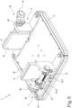
Figure 5 schematically depicts a perspective view of another embodiment of the gripper, in accordance with the description; -
Figure 6 schematically depicts a perspective view of a conveying apparatus for packages comprising a gripper, in accordance with the description; -
Figure 7 schematically depicts a side view of a conveying apparatus, in accordance with the description; -
Figure 8 schematically depicts a top view of a conveying apparatus, in accordance with the description; -
Figure 9 shows, a block diagram of a packaging line, in accordance with the description. - The invention concerns a
gripper 1 for handlingpackages 2, in particular packages filled with a pourable product, in particular a pourable food product. The gripped is suitable for coupling with a carrier of a planar motor system. - The
gripper 1 comprises asupport platform 3 to carry at least apackage 2. Preferably, thesupport platform 3 defines a supporting plane A. - In other words, the
package 2 can be arranged on the supporting plane A defined by thesupport platform 3 of thegripper 1. - The
gripper 1 comprises aretaining device 4, carried by thesupport platform 3. The retainingdevice 4 is movable between an open configuration C1, at which it allows for receiving or releasing thepackage 2, and a retaining configuration C2, at which it retains thepackage 2. - The retaining
device 4 comprises afirst wall 5 and asecond wall 6 presenting each one arespective surface surfaces - The retaining
device 4 defines a receivingspace 8 between the first and thesecond wall package 2 on thesupport platform 3. Advantageously, the receivingspace 8 allows thepackage 2 to be positioned on thesupport platform 3 between the first andsecond walls - The
second wall 6 is linearly movable along a direction of advancement D, e.g. parallel to the supporting plane A, between a first position P1 and a second position P2. - The first position P1 of the
second wall 6 defines the open configuration C1 of the retainingdevice 4, at which thesecond wall 6 is moved away from thefirst wall 5. - The second position P2 of the
second wall 6 defines the retaining configuration C2 of the retainingdevice 4, at which thesecond wall 6 is moved towards to thefirst wall 5. - In the second position P2 of the
second wall 6, considering a package accommodated upon thesupport platform 3 of thegripper 1, thesurfaces second wall second surface package 2. In particular, thefirst surface 21 is opposite to thesecond surface 22. - The linear movement of the
second wall 6 along the direction of advancement D from the first position P1 towards the second position P2 comprises approaching thefirst wall 5. - The
entire surface 61 of thesecond wall 6 may come into contact with thesecond surface 22 of thepackage 2, in particular theentire surface 61 may contact thesecond surface 22 at the same time. - Advantageously, the linear motion of the
second wall 6 allows for approaching thepackage 2 across itsentire surface 61. - Advantageously, the linear motion of the
second wall 6 from the first position P1 to the second position P2 allows for accommodating thepackage 2 by pushing it towards thefirst wall 5. - In the second position P2, the
first wall 5 and thesecond wall 6 are configured to be placed in contact to the respective first andsecond surface package 2, in particular by means of therespective surfaces second walls package 2 itself held between thesurfaces package 2 between twowalls package 2 on thegripper 1. - Advantageously, the contact between the
walls second surfaces package 2 through theentire surfaces walls second wall 6, helps preserve the integrity of thepackage 2 and prevents damages. In fact, the retaining force is distributed across theentire surface package 2. - Preferably, the
surface 51 of thefirst wall 5 is planar. - Preferably, the
surface 61 of thesecond wall 6 is planar. - According to an embodiment, the
surface 61 of thesecond wall 6 is square shaped. Advantageously, a surface square shaped in contact with the external surface of thepackage 2 ensures, in the retaining configuration C2, the distribution of the retaining force, preventing damages to thepackage 2 during retention. - Preferably, the
surface 51 of thefirst wall 5 is square shaped. - According to an aspect of the description, the
surface 61 of thesecond wall 6 and/or thesurface 51 of thefirst wall 5 defines an area between 20 and 50 cm2, preferably between 25 and 39 cm2. - According to a preferred embodiment, the
surface second wall package 2. For example, thesurface - The
surface second wall package 2. In particular, thesurfaces second wall - Preferably, each of the
first wall 5 and thesecond wall 6 comprises a layer or coating made of rubber material, defining itsrespective surface - Advantageously, a
surface external surfaces package 2 in the retaining configuration C2 ensures an improved level of friction between thepackage 2 and thesurface wall - The greater the friction between the
surface package 2, the more secure the retainment of thepackage 2 becomes. - In particular a high level of friction ensures the transportation of
package 2 by thegripper 1 without the risk ofpackages 2 dislodgment. - Advantageously, rubber material adapt itself upon contact with
package 2, thereby preventing damages to thepackage 2. - In a preferred embodiment, the
gripper 1 comprises a connectingelement 9 between the first and thesecond wall first wall 5, thesecond wall 6 and the connectingelement 9 partially surround said receivingspace 8. - The connecting
element 9 is configured to contact thepackage 2 at athird surface 23 thereof. Thethird surface 23 may be different from the first andsecond surface - In other words, when the
package 2 is positioned on thesupport platform 3, through the receivingspace 8, it is in contact with the connectingelement 9. - The connecting
element 9 is, for example, a bar, a rod, or a wall. - Preferably, the connecting
element 9 is coupled with astationary portion 17 of theretaining devices 4 connected to thefirst wall 5 and optionally with astationary portion 15 of theretaining devices 4 connected to thesecond wall 6. Advantageously, the connectingelement 9 defines a stop position for thepackage 2 when it is positioned on thesupport platform 3 through the receivingspace 8. Advantageously, the connectingelement 9 improves security and stability of the retainment in the transportation of thepackage 2. - Advantageously, the connecting
element 9 enhances the accuracy of the positioning of thepackage 2 upon thesupport platform 3 of thegripper 1. Preferably, the connectingelement 9 comprises a layer made of deformable and/or anti-slip material, such as described previously, covering at least a portion of a surface of the connectingelement 9 oriented towards thepackage 2. - The accuracy of the
package 2 positioning on thegripper 1 is crucial within operational station for the execution of additional procedures, such as the capping, towards which the gripper can transport thepackage 2. - Preferably, considering the
first wall 5 stationary, the connectingelement 9 is coupled with thefirst wall 5 and with a stationary portion of thegripper 1 of thesecond wall 6. - To clarify, a stationary portion of the
gripper 1, is an element of thegripper 1 that does not change its position with respect to thesupport platform 3 considering a movement of thesecond wall 6 between the first position P1 and the second position P2. - Preferably, the retaining
device 4 comprises astop element 42 for stopping the movement of thesecond wall 6 in the first position P1 or in the second position P2. In particular, as illustrated infigure 2B , the retainingdevice 4 can comprise a first stop element 42A, for stopping the movement of thesecond wall 6 in the second position P2 and a second stop element 42B for stopping the movement of thesecond wall 6 in the first position P1. - In an embodiment, as shown in
figure 1A , the retainingdevice 4 comprises a slider-crank mechanism 81 configured to move thesecond wall 6 between the first position P1 and the second position P2. - Stated differently, the slider-
crank mechanism 81 causes the movement of thesecond wall 6 between the first position P1 and the second position P2 along the direction of advancement D. - Preferably, as shown in
figure 4B the slider-crank mechanism 81 comprises a crank 82 and ashaft 83 rotatable around its own axis A1. - The
crank 82 is connected to theshaft 83 to rotate around the axis A1 of theshaft 83 and to transmit rotational motion to it. - The slider-
crank mechanism 81 comprises afirst arm 84, connected to theshaft 83 to rotate together with theshaft 83 around its axis A1, and asecond arm 85, hinged to thesecond wall 6. - The
first arm 84 and thesecond arm 85 are hinged together for allowing them to rotate relative to each other around an axis A2 parallel to the axis A1 of theshaft 83. - For enhanced clarity, when the
crank 82 rotates around the axis A1 of theshaft 83, theshaft 83 itself rotates in unison around its own axis A1; this rotation of theshaft 83 leads to thefirst arm 84 rotating around the axis A1 of theshaft 83. The motion of thefirst arm 84 results in a reciprocal rotation of the first andsecond arms shaft 83. This movement of thesecond arm 85 enables the transmission of linear motion to thesecond wall 6 between the first and second positions P1, P2. - The slider-
crank mechanism 81 transforms the rotational motion of thecrank 82 in the linear motion of thesecond wall 6. - In particular, a rotation of the
crank 82 around an axis A1 perpendicular to the direction of advancement D (and, preferably parallel to the supporting plane A) transmits the linear translational motion along the direction of advancement D to thesecond wall 6. - Preferably, the second stop element 42B is configured to stop the rotation of the
crank 82 in a position corresponding to the first position P1 of thesecond wall 6. Preferably, the first stop element 42A is configured to stop the rotation of thecrank 82 in a position corresponding to the second position P2 of thesecond wall 6. - According to an aspect, the first stop element 42A and the second stop element 42B are fixed pins connected to a stationary portion of the
gripper 1. - In an alternative embodiment, as shown in
figure 3A , the retainingdevice 4 comprises abar linkage mechanism 72 configured to move thesecond wall 6 between the first position P1 and the second position P2. - Preferably, the
bar linkage mechanism 72 comprises avertical bar 73 hinged to at least a first bar 74 and asecond bar 75, the first bar 74 being hinged to a stationary portion of the retainingdevice 4, thesecond bar 75 being hinged to thesecond wall 6, the vertical bar being movable along a vertical direction V orthogonal to direction of advancement D. - The vertical direction V of movement of the
vertical bar 73 is orthogonal to the direction of advancement D (and, preferably parallel to the supporting plane A). - In particular, a vertical translation of the
vertical bar 73 results in the rotation of the first bar andsecond bars 74, 75 around the respective hinge at which they are hinged to thevertical bar 73; that rotation results in a rotation of the first bar 74 around the respective hinge at which it is hinged to a stationary portion of the retainingdevice 4 and in a rotation of thesecond bar 75 around the respective hinge at which it is hinged to thesecond wall 6; these movements results in the linear translational motion along the direction of advancement D of thesecond wall 6 between the first position P1 and the second position P2. - To clarify, the
bar linkage mechanism 72 causes the movement of thesecond wall 6 between the first position P1 and the second position P2 along the direction of advancement D. - According to a preferred embodiment, the
bar linkage mechanism 72 comprises avertical bar 73 hinged to the first bar 74, thesecond bar 75, athird bar 76, a fourth bar 77. - The first bar 74 and the
third bar 76 are hinged to a stationary portion of the retainingdevice 4. - The
second bar 75 and the fourth bar 77 are hinged to thesecond wall 6. - The
bar linkage mechanism 72 defines two parallelogram linkages: a first parallelogram linkage defined by the first bar 74, thevertical bar 73, thethird bar 76 and the stationary portion of the retainingdevice 4; a second parallelogram linkage defined by thesecond bar 75, thevertical bar 73, the fourth bar 77 and thesecond wall 6. - The
vertical bar 73 is in common to the two parallelogram linkages. - The first bar 74 and the
third bar 76 are parallel to each other. - The
second bar 75 and the fourth bar 77 are parallel to each other. - Preferably, the first bar 74, the
second bar 75 are all of the same length. Preferably, thethird bar 76 and the fourth bar 77 are all of the same length. Advantageously, the two described parallelogram linkages ensure that thevertical bar 73 moves exclusively in the vertical direction V. - In particular, a vertical translation of the
vertical bar 73 results in the rotation of the first bar 74, thesecond bar 75, thethird bar 76 and the fourth bar 77 around the respective hinge at which they are hinged to thevertical bar 73; that rotation results in a rotation of the first andthird bars 74, 76 around the respective hinges at which they are hinged to the stationary portion of the retainingdevice 4 and in a rotation of the second andfourth bars 75, 77 around the respective hinges at which they are hinged to thesecond wall 6; these movements results in the linear translational motion along the direction of advancement D of thesecond wall 6 between the first position P1 and the second position P2. - Preferably, the second stop element 42B is configured to stop the movement of the
vertical bar 73 along the vertical direction V at a higher level corresponding to the first position P1 of thesecond wall 6. - Preferably, the first stop element 42A is configured to stop the movement of the
vertical bar 73 along the vertical direction V at a lower level corresponding to the second position P2 of thesecond wall 6. - Specifically, the higher and the lower levels of the
vertical bar 73, determined by the first and the second stop element 42A, 42B respectively, are designed such that: moving thevertical bar 73 from the higher level to the lower level results in a linear motion of thesecond wall 6 from the first position P1 to the second position P2, while moving thevertical bar 73 from the lower level to the higher level results in a linear motion of thesecond wall 6 from the second position P2 to the first position P1. - In another alternative embodiment, not shown in the appended figures, the retaining
device 4 comprises a wheel, movable along a vertical direction, in contact with a flat element inclined with respect to the plane A defined by thesupport platform 3. - The movement of the wheel along the vertical direction results in a displacement of the inclined flat element along the direction of advancement D causing the movement of the
second wall 6 between the first and second positions P1, P2. - In an embodiment, the
gripper 1 comprises a linear guide 10, running along said direction of advancement D, for moving thesecond wall 6 along the direction of advancement D. - Advantageously, the linear guide 10 guides the movement of the
second wall 6 along the direction of advancement D. - Guiding the movement of the
second wall 6 through the linear guide 10 ensures that the movement is along said direction D. - Preferably, the
gripper 1 comprises at least a slidingelement 12 for sliding along said linear guide 10. - The sliding
element 12 is connected to thesecond wall 6 for moving thesecond wall 6 along said direction of advancement D. - According to an aspect of the description, the
gripper 1 comprises at least two linear guides 10, running along said direction of advancement D, and respective slidingelement 12 for sliding along said linear guides 10. - In an embodiment, the linear guide 10 is a prismatic guide 7.
- In another embodiment, the linear guide 10 is a circular section guide 11. Advantageously, comprising two linear circular section guides 11 ensures that the sliding
element 12 does not rotate around a linear circular section guide 11 axis. According to an aspect of the present description, thesecond wall 6 is bistable in the first and in the second position P1, P2. - The term bistable refers to the mechanical condition of bistability of a mechanical system. In particular, the retaining device 4 (in every embodiment aforementioned) exists in two distinct stable equilibrium states corresponding to the first position P1 and the second position P2 of the
second wall 6. - In other words, the
second wall 6 can be stable both in the first position P1 and the second position P2 and is capable of transitioning from one position to the other only in response to specific conditions or inputs by the retainingdevice 4. An example of a specific condition or input, considering thebars linkage mechanism 72 embodiment of the retainingdevice 4, is the vertical movement of thevertical bar 73 that results in the linear movement of thesecond wall 6 from the first position P1 to the second position P2, and vice versa. - In fact, considering that embodiment, the first stop element 42A effectively ensures the stability of the
second wall 6 in its second position P2, preventing thevertical bar 73 moving below the lower level. - Moving the
vertical bar 73 below said threshold lower level, thebars linkage mechanism 72 would consequently move resulting in a return of thesecond wall 6 from the second position P2 to the first position P1. - Therefore, the
first stop element 42, 42A is configured to define a condition of stability of thesecond wall 6 in said second position P2. - Advantageously, bistability ensures a reliable switching mechanism from the first and the second position P1, P2 of the
second wall 6. Advantageously, thanks to bistability, thesecond wall 6 can be maintained in the first or second position P1, P2 and any involuntary movement of thesecond wall 6 is minimized. - Preferably, the retaining
device 4 comprises a holding element 13 configured to hold thesecond wall 6 in the first position P1 or in the second position P2. Please note that in the appended drawings, the holding element 13 is configured to hold thesecond wall 6 in the first position P1. - According to an embodiment, the holding element 13 is a magnetic element.
- In particular, the magnetic holding element 13 is configured to maintain the
second wall 6 back into the first position P1, corresponding to the open configuration C1, making thesecond wall 6 stable in that position, in particular by means magnetic attraction. For example, thesecond wall 6 may comprise a ferromagnetic element or thesurface 61 of thesecond wall 6 may comprise a magnetic element. In the latter case, the magnetic element of thesurface 61 and the holding element 13 may have opposite magnetic polarities and the magnetic element of thesurface 61 may be configured to be attracted to the holding element 13. - Advantageously, the holding element 13 allows for minimizing clearance.
- Advantageously, the magnetic holding element 13 allows for minimizing vibrations. In an alternative embodiment, the holding element 13 comprises at least a spring 14 connected to the
second wall 6 and configured to retrieve thesecond wall 6 in the first position P1 (according to the appended drawings) or in the second position P2. - In particular, the spring 14 draws the
second wall 6 back into the first position P1, corresponding to the open configuration C1, making thesecond wall 6 stable in that position. - The spring 14 is preferably anchored at a first end to a
stationary portion 15 of thegripper 1 and at a second end to aportion 16 of the retainingdevice 4 that moves solidly with respect to thesecond wall 6 along the direction of advancement D. To clarify, thestationary portion 15 of thegripper 1, is an element of the gripper that does not change its position with respect to thesupport platform 3 considering a movement of thesecond wall 6 between the first position P1 and the second position P2. - In particular, the spring 14 has its equilibrium position when the
second wall 6 is in the first position P1 which corresponds to the open configuration C1 of the retainingdevice 4. - According to an aspect of the present description, the projection of the retaining
device 4 falls within anarea 30 defined by thesupport platform 3. - To clarify, considering each component of the retaining
device 4, its projection falls within thearea 30 defined by thesupport platform 3. - In other words, the spatial footprint of the retaining
device 4 does not exceed the volume of a solid with thesupport platform 3 as its base and lateral surfaces perpendicular to the supporting plane A established by thesupport platform 3. Advantageously, these features allow two ormore grippers 1 to work closer without impeding each other. - Preferably, the
gripper 1 extends more in height than in width. - In an embodiment, the
first wall 5 is linearly movable along the direction of advancement D between a first position P1 defining said open configuration C1 of the retainingdevice 4, at which thefirst wall 5 is moved away from thesecond wall 6, and a second position P2 defining the retaining configuration C2 of the retainingdevice 4, at which thefirst wall 5 is moved towards to thesecond wall 6. - In other words, also the
first wall 5 is linearly movable to retain and release thepackage 2. - Any aforementioned features regarding the
second wall 6, and the associated advantages, can also be applied to thefirst wall 5. - According to an alternative embodiment, the
first wall 5 is fixed with respect to thesupport platform 3. - Advantageously, having the
first wall 5 fixed with respect to thesupport platform 3 allows accurately determining the positioning of thepackage 2 on thegripper 1 when thepackage 2 is held, that is, when the retainingdevice 4 is in the retaining configuration C2. - According to the present description, it is further disclosed a conveying
apparatus 100 for advancingpackages 2, inparticular packages 2 filled with a pourable product, in particular a pourable food product. - The conveying
apparatus 100 comprises at least agripper 1, comprising one or more of the aforementioned features and presenting the associated advantages. - The conveying
apparatus 100 comprises aplanar motor system 103, comprising a plurality ofcarriers 109, abase element 104 and a control unit U configured for selectively and independently moving thecarriers 109 over thebase element 104. Thesupport platform 3 of thegripper 1 may be coupled to a first surface of thecarrier 109. The first surface may face away from thebase element 104. - The
carriers 109 comprise a second surface, opposite to the first surface, comprising a plurality of magnets. The second surface may face towards thebase element 104. Preferably, thebase element 104 comprises a plurality of coils and the control unit U is configured to energize the coils to move eachcarrier 109 by means of magnetic interaction between the magnets of thecarrier 109 and the magnetic field generated by the coils. - In other words, the
planar motor system 103 moves thecarriers 109, and in turn thegrippers 1, to transport therespective packages 2 they retain over thebase element 104. - The
planar motor system 103 may comprise one or more operational stations for the execution of additional procedures. Thecarriers 109 may be configured to move over thebase element 104 at one or more such operational stations. - The conveying
apparatus 100 comprises aretaining system 110 for controlling each retainingdevice 4 from the respective open configuration C1 into the respective retaining configuration C2 and from the respective retaining configuration C2 into the respective open configuration C1. - Advantageously, the retaining
system 110 of the conveyingapparatus 100 controls the retention and the release of thepackage 2 from thegripper 1 through the control of the retainingdevice 4. - According to a preferred embodiment, the retaining
system 110 comprises: - at least an
inlet cam mechanism 111 comprising at least aninlet cam profile 112, to control the retainingdevice 4 from the open configuration C1 to the retaining configuration C2, and - at least an
outlet cam mechanism 113 comprising at least anoutlet cam profile 114, to control the retainingdevice 4 from the retaining configuration C2 to the open configuration C1. - According to said embodiment, the retaining
device 4 comprises at least onecam follower 41, configured to interact with the at least oneinlet cam profile 112 and with the at least oneoutlet cam profile 114 to define the linear movement of at least thesecond wall 6 between said first position P1 and said second position P2. Stated differently, thecam follower 41 follows theinlet cam profile 112 determining the switch of the retainingdevice 4 from the open configuration C1 to the retaining configuration C2. - Preferably, the
cam follower 41, following theinlet cam profile 112 is moved from a higher level to a lower level switching from the open configuration C1 to the retaining configuration C2 of the retainingdevice 4. - In particular, considering, for example, the embodiment illustrated in
figure 3A , in which theretaining device 4 comprises abars linkage mechanism 72, thecam follower 41 is attached to thevertical bar 73; thecam follower 41, following theinlet cam profile 112, is moved from the higher level to a lower level and this movement of thecam follower 41 results in the motion of thevertical bar 73 from the higher level to the lower level. - Stated differently, the
cam follower 41 follows theoutlet cam profile 114 determining the switching of the retainingdevice 4 from the retaining configuration C2 to the open configuration C1. - Preferably, the
cam follower 41, following theoutlet cam profile 114 is moved from a lower level to a higher level switching from the retaining configuration C2 to the open configuration C1 of the retainingdevice 4. - In particular, considering the embodiment illustrated in
figure 3A , in which theretaining device 4 comprises abars linkage mechanism 72, thecam follower 41 is attached to thevertical bar 73; thecam follower 41, following theoutlet cam profile 114, is moved from the lower level to the higher level and this movement of thecam follower 41 results in a motion of thevertical bar 73 from the lower level to the higher level. - Specifically, the higher and the lower levels of the
cam follower 41, determined by the first and the second stop element 42A, 42B respectively, are designed such that: moving thecam follower 41 results in a vertical translation of thevertical bar 73; this, consequently, results in a linear motion of thesecond wall 6 from the first position P1 to the second position P2 when thecam follower 41 passes from the higher level to the lower level, while results in a linear motion of thesecond wall 6 from the second position P2 to the first position P1 when thecam follower 41 passes from the lower level to the higher level. - According to an aspect, the
inlet cam profile 112 and theoutlet cam profile 114 are mirror symmetric with regard to one another. - In particular, considering, for example, the embodiment illustrated in
figure 4B , in which theretaining device 4 comprises a slider-crank mechanism 81, thecam follower 41 is attached to the crank 82; thecam follower 41, following theinlet cam profile 112, is moved from the higher level to a lower level and this movement of thecam follower 41 results in a rotation of thecrank 82 around the axis A1 in a first direction. - In particular, considering the embodiment illustrated in
figure 4B , in which theretaining device 4 comprises a slider-crank mechanism 81, thecam follower 41 is attached to the crank 82; thecam follower 41, following theoutlet cam profile 114, is moved from the lower level to the higher level and this movement of thecam follower 41 results in a rotation of thecrank 82 around the axis A1 in second direction opposite with respect to the first direction of rotation. - According to an aspect, the
inlet cam profile 112 and theoutlet cam profile 114 are mirror symmetric with regard to one another. - Preferably, the
stop element 42 of the retainingdevice 4 is configured for stopping the movement of thecam follower 41 in a position corresponding to the first position P1 or the second position P2 of thesecond wall 6. - In particular, as illustrated in
figure 2B , the retainingdevice 4 can comprise a first stop element 42A, for stopping the movement of thecam follower 41 in a position corresponding to the second position P2 of thesecond wall 6, and a second stop element 42B for stopping the movement of thecam follower 41 in a position corresponding to the first position P1 of thesecond wall 6. - According to an aspect of the description, the conveying
apparatus 100 comprises aninlet station 101 and anoutlet station 102 and it is, preferably configured for advancingpackages 2 from theinlet station 101 to theoutlet station 102. - In an embodiment, the conveying
apparatus 100 comprises: - an
inlet conveyor 105 configured to advance thepackages 2 from theinlet station 101 to a receivingstation 106 at which eachpackage 2 is transferred onto arespective gripper 1, - an
outlet conveyor 107 configured to advance thepackages 2 at least from arelease station 108, at which eachpackage 2 is released from therespective gripper 1 to theoutlet station 102. - The retaining
system 110 are preferably configured for controlling each retainingdevice 4 from the respective open configuration C1 into the respective retaining configuration C2 during receiving arespective package 2 at the receivingstation 106 and to control each retainingdevice 4 from the respective retaining configuration C2 into the respective open configuration C1 during releasing therespective package 2 at therelease station 108. - Preferably, the
cam follower 41 is configured to interact with the at least oneinlet cam profile 112 at theinlet station 101 and with the at least oneoutlet cam profile 114 at theoutlet station 102. - According to an aspect of the description, the
planar motor system 103 is configured to control an advancement of eachgripper 1 along a receivingpath 115 at theinlet station 101. - The retaining
system 110 is configured to control each retainingdevice 4 from the respective open configuration C1 to the respective retaining configuration C2 during said advancement of therespective gripper 1 along at least a portion of the receivingpath 115. - According to an aspect of the description, the
planar motor system 103 is configured to control an advancement of eachcarrier 109, and inturn gripper 1, along arelease path 116 in theoutlet station 102. - The retaining
system 110 is configured to control each retainingdevice 4 from the respective retaining configuration C2 to the respective open configuration C1 during said advancement of therespective gripper 1 along at least a portion of therelease path 116. - In other words, along the receiving
path 115 in theinlet station 101 thegripper 1 retains thepackage 2 and along therelease path 116 in theoutlet station 102 thegripper 1 release thepackage 2. - The
planar motor system 103 controls the movement of thegrippers 1 along the receiving and therelease path - According to the present description, it is further disclosed a
packaging line 200 for producingpackages 2 filled with a pourable product, in particular a pourable food product. - The
packaging line 200 comprises apackaging machine 201 for forming thepackages 2. - The
packaging line 200 comprises ahandling apparatus 202 for handling thepackages 2 after being formed, e.g. a capping station. - The
packaging line 200 comprises at least one conveyingapparatus 100 comprising one or more of the aforementioned features and presenting the associated advantages. The conveyingapparatus 100 may be positioned at the handling apparatus 202 (see the non-limiting example depicted in the figure) and/or at the packaging machine 201.One or more embodiments may thus relate to acarrier 109 for a conveyingapparatus 100. The conveyingapparatus 100 may comprise aplanar motor system 103 comprising a plurality ofcarriers 109, abase element 104 and a control unit U configured for selectively and independently moving thecarriers 109 over thebase element 104. - The
carrier 109 comprises agripper 1 according to one or more embodiments, a first surface coupled to thesupport platform 3 of thegripper 1, and a second surface, opposite to the first surface, comprising a plurality of magnets. The carrier may be a planar carrier. - Accordingly, the conveying apparatus for advancing
packages 2 may comprise: - at least a
carrier 109 as previously described, - a
planar motor system 103, comprising abase element 104 and a control unit U configured for controlling the magnetization of thebase element 104 in order to move selectively and independently each one of saidcarriers 109 over thebase element 104 by means of the plurality of magnets. - The conveying device may further comprise a
retaining system 110 for controlling each retainingdevice 4 from the respective open configuration C1 into the respective retaining configuration C2 and from the respective retaining configuration C2 into the respective open configuration C1.
Claims (18)
- Gripper for handling packages (2), comprising:- a support platform (3) to carry at least a package (2);- a retaining device (4), carried by the support platform (3), movable between an open configuration (C1), at which it allows for receiving or releasing the package (2), and a retaining configuration (C2), at which it retains the package (2),the retaining device (4) comprising a first wall (5) and a second wall (6) presenting each one a respective surface (51, 61), facing each other,the retaining device (4) defining a receiving space (8) between the first and the second wall (5, 6) to accommodate said package (2) on the support platform (3), the second wall (6) being linearly movable along a direction of advancement (D) between a first position (P1) defining said open configuration (C1) of the retaining device (4), at which the second wall (6) is moved away from the first wall (5), and a second position (P2) defining the retaining configuration (C2) of the retaining device (4), at which the second wall (6) is moved towards to the first wall (5).
- Gripper according to claim 1, wherein the surface (51, 61) of the first and/or of the second wall (5, 6) comprises a deformable and/or an anti-slip material.
- Gripper according to any one of the preceding claims, comprising a connecting element (9) between the first and the second wall (5, 6), the first wall (5), second wall (6) and connecting element (9) partially surrounding said receiving space (8).
- Gripper according to any one of the preceding claims, comprising a linear guide (10), running along said direction of advancement (D), for moving the second wall (6) along said direction of advancement (D).
- Gripper according to the preceding claim, comprising at least a sliding element (12) for sliding along said linear guide (10), the sliding element (12) being connected to the second wall (6) for moving the second wall (6) along said direction of advancement (D).
- Gripper according to any one of claims 4 or 5, wherein the linear guide (10) is a prismatic or circular section guide (7).
- Gripper according to any one of the preceding claims, wherein the second wall (6) is bistable in the first and in the second position (P1, P2).
- Gripper according to any one of the preceding claims, wherein the retaining device (4) comprises a holding element (13) configured to hold the second wall (6) in the first position (P1) or in the second position (P2).
- Gripper according to the preceding claim, wherein the holding element (13) is a magnetic element, preferably the second wall (6) comprises a magnetic element configured to attract the holding element (13).
- Gripper according to claim 8, wherein the holding element (13) comprises at least a spring (14) connected to the second wall (6) and configured to retrieve the second wall (6) in the first position (P1) or in the second position (P2).
- Gripper according to any one of the preceding claims, wherein the retaining device (4) comprises at least a stop element (42) configured to stop the linear movement of the second wall (6) in the second position (P2) or in the first position (P1).
- Gripper according to any one of the preceding claims, wherein the projection of the retaining device (4) falls within an area (30) defined by the support platform (3).
- Gripper according to any one of the preceding claims, wherein the first wall (5) is linearly movable along the direction of advancement (D) between a first position (P1) defining said open configuration (C1) of the retaining device (4), at which the first wall (5) is moved away from the second wall (6), and a second position (P2) defining the retaining configuration (C2) of the retaining device (4), at which the first wall (5) is moved towards to the second wall (6).
- Gripper according to any one of claims 1 to 12, wherein the first wall (5) is fixed with respect to the support platform (3).
- A carrier (109) for a conveying apparatus (100) comprising a planar motor system (103), the carrier (109) comprising:- a gripper (1) according to any one of the preceding claims,- a first surface coupled to the support platform (3),- a second surface, opposite to the first surface, comprising a plurality of magnets.
- Conveying apparatus for advancing packages (2) comprising:- at least a carrier (109) according to the preceding claim,- a planar motor system (103), comprising a magnetizable base element (104) and a control unit (U) configured for controlling the magnetization of the base element (104) in order to move selectively and independently each one of said carriers (109) over the base element (104) by means of the plurality of magnets;- a retaining system (110) for controlling each retaining device (4) from the respective open configuration (C1) into the respective retaining configuration (C2) and from the respective retaining configuration (C2) into the respective open configuration (C1).
- Conveying apparatus according to the preceding claim, wherein the retaining system (110) comprises:- at least an inlet cam mechanism (111) comprising at least an inlet cam profile (112), to control the retaining device (4) from the open configuration (C1) to the retaining configuration (C2),- at least an outlet cam mechanism (113) comprising at least an outlet cam profile (114), to control the retaining device (4) from the retaining configuration (C2) to the open configuration (C1),the retaining device (4) comprising at least one cam follower (41) configured to interact with the at least one inlet cam profile (112) and with the at least one outlet cam profile (114) to define the linear movement of at least the second wall (6) between said first position (P1) and said second position (P2).
- Packaging line for producing packages (2) filled with a pourable product comprising at least one conveying apparatus (100) according to any one of the claims 16 or 17.
Applications Claiming Priority (1)
| Application Number | Priority Date | Filing Date | Title |
|---|---|---|---|
| IT102023000026358A IT202300026358A1 (en) | 2023-12-11 | 2023-12-11 | PACKAGE PICKING GRIPPER, PACKAGE CONVEYING APPARATUS COMPRISING A GRIPPER AND PACKAGING LINE WITH CONVEYING APPARATUS |
Publications (2)
| Publication Number | Publication Date |
|---|---|
| EP4570712A2 true EP4570712A2 (en) | 2025-06-18 |
| EP4570712A3 EP4570712A3 (en) | 2025-08-13 |
Family
ID=89983520
Family Applications (1)
| Application Number | Title | Priority Date | Filing Date |
|---|---|---|---|
| EP24218228.5A Pending EP4570712A3 (en) | 2023-12-11 | 2024-12-09 | Gripper for picking up packages, conveying apparatus for packages comprising a gripper and packaging line having a conveying apparatus |
Country Status (3)
| Country | Link |
|---|---|
| EP (1) | EP4570712A3 (en) |
| IT (1) | IT202300026358A1 (en) |
| WO (1) | WO2025125120A1 (en) |
Family Cites Families (5)
| Publication number | Priority date | Publication date | Assignee | Title |
|---|---|---|---|---|
| EP1215144A1 (en) * | 2000-12-05 | 2002-06-19 | Tetra Laval Holdings & Finance SA | Device for conveying sealed packages |
| US7036658B2 (en) * | 2003-11-13 | 2006-05-02 | Hartness International, Inc. | Gripper conveyor with clear conveying path and related conveyor link |
| FR3088061A1 (en) * | 2018-11-07 | 2020-05-08 | C.E.R.M.E.X. Constructions Etudes Et Recherches De Materiels Pour L'emballage D'expedition | DEVICE FOR HOLDING A PRODUCT AND PRODUCT CONVEYING DEVICE |
| ES2995078T3 (en) * | 2019-01-29 | 2025-02-06 | Ocme Srl | Handling system of containers equipped with a mouthpiece and a symmetry plane passing through the mouthpiece and relative handling method of said containers |
| EP3947217A4 (en) * | 2019-03-29 | 2022-05-11 | Planar Motor Inc. | Robotic device and methods for fabrication, use and control of same |
-
2023
- 2023-12-11 IT IT102023000026358A patent/IT202300026358A1/en unknown
-
2024
- 2024-12-09 EP EP24218228.5A patent/EP4570712A3/en active Pending
- 2024-12-09 WO PCT/EP2024/085187 patent/WO2025125120A1/en active Pending
Also Published As
| Publication number | Publication date |
|---|---|
| WO2025125120A1 (en) | 2025-06-19 |
| IT202300026358A1 (en) | 2025-06-11 |
| EP4570712A3 (en) | 2025-08-13 |
Similar Documents
| Publication | Publication Date | Title |
|---|---|---|
| TWI889792B (en) | Plant for processing containers | |
| EP3656707B1 (en) | Handling of containers in a system for production of packaged food products | |
| US9403611B2 (en) | Unit for sequencing and guiding items | |
| RU2445243C2 (en) | Device for grouping packages along transfer path | |
| US9120636B2 (en) | Method for moving a reel of packaging material from a storage station to a supply station of a packaging unit for producing sealed packages of food product, and clamping unit for clamping such reel | |
| RU2136553C1 (en) | Method of transportation of objects through device (versions), packing device (versions) and method of material packing into card-board packs (versions) | |
| EP4003845B1 (en) | An article picking and treating apparatus | |
| CN105905520B (en) | Machine and method for transferring articles | |
| JP2019517963A (en) | Device and method for packing cushioning elements in cartons | |
| CN115515870B (en) | Extraction system for extracting items from boxes | |
| CA2762409A1 (en) | System, gripping head, and method for displacing products | |
| EP4310027A1 (en) | Conveying apparatus for a packaging machine, packaging machine having a conveying apparatus and a carrier for a conveying apparatus | |
| ES2975297T3 (en) | Packaging machine with clamp system | |
| WO2025125120A1 (en) | Gripper for picking up packages, conveying apparatus for packages comprising a gripper and packaging line having a conveying apparatus | |
| JP7135733B2 (en) | Goods transfer equipment | |
| WO2015112018A1 (en) | Gripper unit for gripping, picking up, transporting, and discharging boxes | |
| KR102516341B1 (en) | Variable gripper device for container transfer | |
| KR20170020024A (en) | Apparatus and method for loading a box | |
| EP1215144A1 (en) | Device for conveying sealed packages | |
| US20220306331A1 (en) | Fast changeover cartoner | |
| KR102526097B1 (en) | automatic installing and packaging apparatus and method | |
| KR102030917B1 (en) | A pouch opening apparatus for rotary packaging machine | |
| WO2025094070A1 (en) | Assembly for magnetic transport | |
| JP2019500291A (en) | Device and method for aligning a blank in a magazine holding several blanks and apparatus and method for removing a blank from a magazine holding several blanks | |
| JPH11171133A (en) | Pack battery box packing device |
Legal Events
| Date | Code | Title | Description |
|---|---|---|---|
| PUAI | Public reference made under article 153(3) epc to a published international application that has entered the european phase |
Free format text: ORIGINAL CODE: 0009012 |
|
| STAA | Information on the status of an ep patent application or granted ep patent |
Free format text: STATUS: THE APPLICATION HAS BEEN PUBLISHED |
|
| AK | Designated contracting states |
Kind code of ref document: A2 Designated state(s): AL AT BE BG CH CY CZ DE DK EE ES FI FR GB GR HR HU IE IS IT LI LT LU LV MC ME MK MT NL NO PL PT RO RS SE SI SK SM TR |
|
| PUAL | Search report despatched |
Free format text: ORIGINAL CODE: 0009013 |
|
| AK | Designated contracting states |
Kind code of ref document: A3 Designated state(s): AL AT BE BG CH CY CZ DE DK EE ES FI FR GB GR HR HU IE IS IT LI LT LU LV MC ME MK MT NL NO PL PT RO RS SE SI SK SM TR |
|
| RIC1 | Information provided on ipc code assigned before grant |
Ipc: B65G 15/58 20060101AFI20250708BHEP Ipc: B65G 17/32 20060101ALI20250708BHEP Ipc: B65G 17/46 20060101ALI20250708BHEP Ipc: B65G 35/06 20060101ALI20250708BHEP Ipc: B65G 54/02 20060101ALI20250708BHEP Ipc: H02K 41/03 20060101ALI20250708BHEP |
|
| STAA | Information on the status of an ep patent application or granted ep patent |
Free format text: STATUS: REQUEST FOR EXAMINATION WAS MADE |
|
| 17P | Request for examination filed |
Effective date: 20260213 |