EP4570600A1 - Airbag system - Google Patents
Airbag system Download PDFInfo
- Publication number
- EP4570600A1 EP4570600A1 EP23865327.3A EP23865327A EP4570600A1 EP 4570600 A1 EP4570600 A1 EP 4570600A1 EP 23865327 A EP23865327 A EP 23865327A EP 4570600 A1 EP4570600 A1 EP 4570600A1
- Authority
- EP
- European Patent Office
- Prior art keywords
- airbag
- vehicle
- seat
- inflated
- deployed
- Prior art date
- Legal status (The legal status is an assumption and is not a legal conclusion. Google has not performed a legal analysis and makes no representation as to the accuracy of the status listed.)
- Pending
Links
Images



Classifications
-
- B—PERFORMING OPERATIONS; TRANSPORTING
- B60—VEHICLES IN GENERAL
- B60R—VEHICLES, VEHICLE FITTINGS, OR VEHICLE PARTS, NOT OTHERWISE PROVIDED FOR
- B60R21/00—Arrangements or fittings on vehicles for protecting or preventing injuries to occupants or pedestrians in case of accidents or other traffic risks
- B60R21/02—Occupant safety arrangements or fittings, e.g. crash pads
- B60R21/16—Inflatable occupant restraints or confinements designed to inflate upon impact or impending impact, e.g. air bags
- B60R21/23—Inflatable members
- B60R21/231—Inflatable members characterised by their shape, construction or spatial configuration
- B60R21/23138—Inflatable members characterised by their shape, construction or spatial configuration specially adapted for side protection
-
- B—PERFORMING OPERATIONS; TRANSPORTING
- B60—VEHICLES IN GENERAL
- B60R—VEHICLES, VEHICLE FITTINGS, OR VEHICLE PARTS, NOT OTHERWISE PROVIDED FOR
- B60R21/00—Arrangements or fittings on vehicles for protecting or preventing injuries to occupants or pedestrians in case of accidents or other traffic risks
- B60R21/02—Occupant safety arrangements or fittings, e.g. crash pads
- B60R21/16—Inflatable occupant restraints or confinements designed to inflate upon impact or impending impact, e.g. air bags
- B60R21/20—Arrangements for storing inflatable members in their non-use or deflated condition; Arrangement or mounting of air bag modules or components
- B60R21/203—Arrangements for storing inflatable members in their non-use or deflated condition; Arrangement or mounting of air bag modules or components in steering wheels or steering columns
-
- B—PERFORMING OPERATIONS; TRANSPORTING
- B60—VEHICLES IN GENERAL
- B60R—VEHICLES, VEHICLE FITTINGS, OR VEHICLE PARTS, NOT OTHERWISE PROVIDED FOR
- B60R21/00—Arrangements or fittings on vehicles for protecting or preventing injuries to occupants or pedestrians in case of accidents or other traffic risks
- B60R21/02—Occupant safety arrangements or fittings, e.g. crash pads
- B60R21/16—Inflatable occupant restraints or confinements designed to inflate upon impact or impending impact, e.g. air bags
- B60R21/20—Arrangements for storing inflatable members in their non-use or deflated condition; Arrangement or mounting of air bag modules or components
- B60R21/207—Arrangements for storing inflatable members in their non-use or deflated condition; Arrangement or mounting of air bag modules or components in vehicle seats
-
- B—PERFORMING OPERATIONS; TRANSPORTING
- B60—VEHICLES IN GENERAL
- B60R—VEHICLES, VEHICLE FITTINGS, OR VEHICLE PARTS, NOT OTHERWISE PROVIDED FOR
- B60R21/00—Arrangements or fittings on vehicles for protecting or preventing injuries to occupants or pedestrians in case of accidents or other traffic risks
- B60R21/02—Occupant safety arrangements or fittings, e.g. crash pads
- B60R21/16—Inflatable occupant restraints or confinements designed to inflate upon impact or impending impact, e.g. air bags
- B60R21/23—Inflatable members
- B60R21/231—Inflatable members characterised by their shape, construction or spatial configuration
- B60R21/233—Inflatable members characterised by their shape, construction or spatial configuration comprising a plurality of individual compartments; comprising two or more bag-like members, one within the other
-
- B—PERFORMING OPERATIONS; TRANSPORTING
- B60—VEHICLES IN GENERAL
- B60R—VEHICLES, VEHICLE FITTINGS, OR VEHICLE PARTS, NOT OTHERWISE PROVIDED FOR
- B60R21/00—Arrangements or fittings on vehicles for protecting or preventing injuries to occupants or pedestrians in case of accidents or other traffic risks
- B60R2021/0002—Type of accident
- B60R2021/0006—Lateral collision
-
- B—PERFORMING OPERATIONS; TRANSPORTING
- B60—VEHICLES IN GENERAL
- B60R—VEHICLES, VEHICLE FITTINGS, OR VEHICLE PARTS, NOT OTHERWISE PROVIDED FOR
- B60R21/00—Arrangements or fittings on vehicles for protecting or preventing injuries to occupants or pedestrians in case of accidents or other traffic risks
- B60R21/02—Occupant safety arrangements or fittings, e.g. crash pads
- B60R21/16—Inflatable occupant restraints or confinements designed to inflate upon impact or impending impact, e.g. air bags
- B60R2021/161—Inflatable occupant restraints or confinements designed to inflate upon impact or impending impact, e.g. air bags characterised by additional means for controlling deployment trajectory
-
- B—PERFORMING OPERATIONS; TRANSPORTING
- B60—VEHICLES IN GENERAL
- B60R—VEHICLES, VEHICLE FITTINGS, OR VEHICLE PARTS, NOT OTHERWISE PROVIDED FOR
- B60R21/00—Arrangements or fittings on vehicles for protecting or preventing injuries to occupants or pedestrians in case of accidents or other traffic risks
- B60R21/02—Occupant safety arrangements or fittings, e.g. crash pads
- B60R21/16—Inflatable occupant restraints or confinements designed to inflate upon impact or impending impact, e.g. air bags
- B60R21/23—Inflatable members
- B60R21/231—Inflatable members characterised by their shape, construction or spatial configuration
- B60R2021/23107—Inflatable members characterised by their shape, construction or spatial configuration the bag being integrated in a multi-bag system
-
- B—PERFORMING OPERATIONS; TRANSPORTING
- B60—VEHICLES IN GENERAL
- B60R—VEHICLES, VEHICLE FITTINGS, OR VEHICLE PARTS, NOT OTHERWISE PROVIDED FOR
- B60R21/00—Arrangements or fittings on vehicles for protecting or preventing injuries to occupants or pedestrians in case of accidents or other traffic risks
- B60R21/02—Occupant safety arrangements or fittings, e.g. crash pads
- B60R21/16—Inflatable occupant restraints or confinements designed to inflate upon impact or impending impact, e.g. air bags
- B60R21/23—Inflatable members
- B60R21/231—Inflatable members characterised by their shape, construction or spatial configuration
- B60R21/23138—Inflatable members characterised by their shape, construction or spatial configuration specially adapted for side protection
- B60R2021/23146—Inflatable members characterised by their shape, construction or spatial configuration specially adapted for side protection seat mounted
-
- B—PERFORMING OPERATIONS; TRANSPORTING
- B60—VEHICLES IN GENERAL
- B60R—VEHICLES, VEHICLE FITTINGS, OR VEHICLE PARTS, NOT OTHERWISE PROVIDED FOR
- B60R21/00—Arrangements or fittings on vehicles for protecting or preventing injuries to occupants or pedestrians in case of accidents or other traffic risks
- B60R21/02—Occupant safety arrangements or fittings, e.g. crash pads
- B60R21/16—Inflatable occupant restraints or confinements designed to inflate upon impact or impending impact, e.g. air bags
- B60R21/23—Inflatable members
- B60R21/231—Inflatable members characterised by their shape, construction or spatial configuration
- B60R2021/23161—Inflatable members characterised by their shape, construction or spatial configuration specially adapted for protecting at least two passengers, e.g. preventing them from hitting each other
-
- B—PERFORMING OPERATIONS; TRANSPORTING
- B60—VEHICLES IN GENERAL
- B60R—VEHICLES, VEHICLE FITTINGS, OR VEHICLE PARTS, NOT OTHERWISE PROVIDED FOR
- B60R21/00—Arrangements or fittings on vehicles for protecting or preventing injuries to occupants or pedestrians in case of accidents or other traffic risks
- B60R21/02—Occupant safety arrangements or fittings, e.g. crash pads
- B60R21/16—Inflatable occupant restraints or confinements designed to inflate upon impact or impending impact, e.g. air bags
- B60R21/20—Arrangements for storing inflatable members in their non-use or deflated condition; Arrangement or mounting of air bag modules or components
- B60R21/205—Arrangements for storing inflatable members in their non-use or deflated condition; Arrangement or mounting of air bag modules or components in dashboards
Definitions
- the present invention relates to an airbag system including a plurality of airbag devices and a control device for inflating and deploying cushions of their respective airbag devices.
- a far-side airbag may be mounted on a side portion on the center side, in the vehicle width direction, of a backrest portion of each vehicle seat.
- an occurrence of a side collision in which a structure such as another vehicle or a utility pole collides with a side door on the front passenger's seat side causes an inertial force at an initial stage of the collision to move an occupant seated in the driver's seat toward the front passenger's seat side.
- the far-side airbag is configured to restrain, when a side collision occurs, an occupant seated in a seat on the opposite side to the collision side from moving toward the collision side.
- a cushion and an inflator are accommodated inside a side portion of the backrest portion.
- inflation gas is supplied from the inflator to the cushion, which starts inflating and deploying the cushion.
- the cushion pops out forward from the position of the side portion of the backrest portion with a part of the cushion still being left in the backrest portion, thereby completing the inflation and deployment of the cushion between the vehicle seats.
- the inflated and deployed cushion restrains the occupant seated on the driver's seat from moving toward the front passenger's seat side.
- a front airbag for the front passenger's seat is known as an airbag device that exhibits restraint performance corresponding to a collision from the front side of a vehicle.
- a front airbag for the front passenger's seat described in Patent Document 2 is accommodated in an instrument panel.
- inflation gas is supplied from the inflator to the cushion, which starts inflating and deploying the cushion.
- a fragile slit formed in the instrument panel lets the cushion pop out toward the rear side of the vehicle, thereby completing the inflation and deployment of the cushion.
- the cushion inflated and deployed as such restrains the occupant seated on the front passenger's seat from moving toward the front side of the vehicle.
- the base portion thereof is fixed to the vehicle's seat side.
- Introduction of an inflation gas into the cushion from the inflator at the time of a side collision inflates and deploys the cushion from the vehicle's seat toward the front side in the vehicle's front-rear direction, and thus the cushion restrains an occupant seated on the vehicle seat.
- the base portion of the cushion is fixed to the vehicle's seat side, whereas the leading end portion of the cushion that the inflation and deployment of the cushion thrust out toward the front side in the vehicle front-rear direction is in a free state. In that state the leading end portion swings to the left and right in the vehicle width direction. Therefore, in the cushion that has completed its inflation and deployment, around the base portion, which may be referred to as "one end,” the leading end portion, which may be referred to as “the other end,” is likely to rotate to the left and right in the horizontal direction.
- a near-side airbag is inflated and deployed so as to face a vehicle body member such as a door.
- the vehicle body member serves as a wall, and the movement of the cushion is easily restricted by the wall.
- the far-side airbag is inflated and deployed at the center, in the vehicle width direction, of the vehicle cabin. It is, therefore, difficult to suppress the rotation and the inclination of the cushion.
- the cushion swings so as to avoid the occupant moving in the vehicle width direction, which makes it difficult to sufficiently and appropriately protect the occupant.
- the upper side of the cushion of the far-side airbag is inclined toward the front passenger's seat side, it is not possible to secure a portion that accurately receives the occupant, which makes it difficult to sufficiently and appropriately protect the occupant.
- the present invention is made in view of such circumstances, and an object of the present invention is to provide an airbag system in which when a cushion of a far-side airbag is inflated and deployed, the vehicle's front side of the cushion is prevented from rotating toward a front passenger's seat and an upper side of the cushion is prevented from tilting toward the front passenger's seat, so that the cushion does not swing or tilt when an occupant is restrained.
- the inventors of the present application considered that an improvement of an airbag system was necessary in order to solve the above-described problem.
- the inventors of the present application have conducted intensive studies to coordinate a front airbag with a far-side airbag in order to improve the occupant restraining performance, because the front airbag has conventionally been intended only to protect an occupant from a frontal collision and does not contribute to protection of the occupant at the time of a side collision.
- the inventors have made the present invention.
- side airbag is used, but the term “side airbag” in this Specification has the same meaning as the term "far-side airbag.”
- the present invention is an airbag system including: a side airbag which is located on a side portion on the center side, in a vehicle's width direction, of one seat of a vehicle and which is inflated and deployed toward a front side of the vehicle; a front airbag that is inflated and deployed at a vehicle's front side of the other seat that is provided adjacent to the one seat of the vehicle in a vehicle width direction; and a control device that, in a side collision, causes the front airbag to be inflated and deployed together with the side air bag.
- a vehicle's front-side end portion of the side airbag is positioned further toward the front side of the vehicle than a vehicle's rear-side end portion of the front airbag.
- the present invention may be configured to include: a side airbag which is located on a side portion on the center side, in the vehicle's width direction and is inflated and deployed toward a vehicle's front side of one seat of a vehicle; a front airbag that is inflated and deployed at the vehicle front side of the one seat of the vehicle; and a control device that, in a side collision of the vehicle, causes the front airbag to be inflated and deployed together with the side airbag.
- a vehicle's front-side end portion of the side airbag is positioned further toward the front side of the vehicle than a vehicle's rear-side end portion of the front airbag.
- the present invention may have a configuration having an overlapping portion at which the side airbag and the front airbag overlap each other when the side airbag inflated and deployed and the front airbag inflated and deployed are perspectively viewed from a lateral direction that is perpendicular to the front-rear direction of the vehicle.
- the present invention may have a configuration where, in an inflation completed state in which the side airbag and the front airbag are completely inflated and deployed respectively, the side airbag has a first contact region that is in contact with the front airbag, and the front airbag has a second contact region that is in contact with the side airbag.
- the present invention may have a configuration where the side airbag includes: a first main chamber that is inflated and deployed toward a vehicle's front side; and a first sub-chamber that is inflated and deployed so as to protrude from the first main chamber toward a center side in a vehicle's width direction, and where the first sub-chamber is provided in the overlapping portion.
- the present invention may have a configuration where the front airbag includes: a second main chamber that is inflated and deployed toward a vehicle's rear side; and a second sub-chamber that is inflated and deployed so as to protrude from the second main chamber toward a center side in a vehicle's width direction, and where the second sub-chamber is provided in the overlapping portion.
- the present invention may have a configuration where the side airbag is provided with a first high-friction portion having a larger friction coefficient than a surface portion of a base fabric panel constituting the side airbag, and where the first high-friction portion includes the first contact region.
- the present invention may have a configuration where the front airbag is provided with a second high-friction portion having a larger friction coefficient than a surface portion of a base fabric panel constituting the front airbag, and where the second high-friction portion includes the second contact region.
- the front airbag may be a front airbag for a front passenger's seat.
- the front airbag may be a driver's front airbag.
- An airbag system of the present invention includes: a side airbag which is located on a side portion on the center side, in a vehicle's width direction, of one seat of a vehicle and which is inflated and deployed toward a front side of the vehicle; a front airbag that is inflated and deployed at a vehicle's front side of the other seat that is provided adjacent to the one seat of the vehicle in a vehicle width direction; and a control device that, in a side collision, causes the front airbag to be inflated and deployed together with the side air bag.
- the front airbag of the present invention when the side airbag inflated and deployed and the front airbag inflated and deployed are viewed from a lateral direction that is perpendicular to a front-rear direction of the vehicle, a vehicle's front-side end portion of the side airbag is positioned further toward the front side of the vehicle than a vehicle's rear-side end portion of the front airbag.
- the front airbag of the present invention can be inflated and deployed also at the time of a side collision, and the inflated and deployed front airbag can be brought into contact with the side airbag.
- the front airbag on the front passenger's seat side serving as a support can suppress the vehicle front side of the cushion from rotating toward the front passenger's seat and can also suppress the upper side of the cushion from tilting toward the front passenger's seat.
- the cushion does not swing or tilt when the occupant is restrained, the occupant-restraining performance is enhanced. Further, since it is not necessary for the side airbag to be the sole provider of the occupant-restraining force, the structure of the side airbag can be simplified.
- occupant in the present invention is an occupant in accordance with a frontal collision test dummy (Hybrid III AM50; human body dummy for frontal collision test set forth in specification [49CFR Part 572 Subpart E and O] of NHTSA [National Highway Traffic Safety Administration]) with a physique equivalent to the average male in the United States; having an approximate size of 175 cm height, 88 cm sitting height, and 78 kg weight.
- a frontal collision test dummy Hybrid III AM50; human body dummy for frontal collision test set forth in specification [49CFR Part 572 Subpart E and O] of NHTSA [National Highway Traffic Safety Administration]
- the present invention can also be applied for other anthropomorphic test dummies.
- the terms “upper” and “upper side” refer to a head direction of an occupant 3 seated in a regular position in a seat, and “lower” and “lower side” refer to a foot direction of the occupant 3.
- the "regular position” refers to a position in a center, in the left-right direction, of a seat cushion of the seat with the back of the occupant 3 in contact with a backrest portion 7 from above and below.
- the terms “front” and “front side” refer to a forward direction of the occupant 3 seated in a seat in the regular position, and “rear” and “rear side” refer to a backward direction of the occupant 3.
- the terms “left” and “left side” refer to a left-hand direction of the occupant 3 seated in a seat in the regular position, and “right” and “right side” refer to the right-hand direction of the occupant 3.
- the "width direction(s)" of the vehicle and the “vehicle width direction(s)” may stand for the same direction(s) as the "right” and “left” direction(s).
- the present embodiment is an airbag system 10 that includes: at least a side airbag 20 and a front airbag 30 for a front passenger's seat; and a control device 40 for controlling, among other things, the timing of starting the inflation and deployment of cushions 21, 31 of their respective airbag devices.
- the airbag system 10 of the present embodiment further includes: a driver's seat side airbag 60, which protects the near side of the occupant 3 seated in the driver's seat 2a; and a front passenger's seat side airbag 70, which protects the near side of the occupant seated in the front passenger's seat 2b.
- a steering wheel 4 is provided in front of the driver's seat 2a.
- the driver's seat 2a specifically the backrest portion 3 thereof accommodates the side airbag 20 in a side portion on the far side thereof.
- the front airbag 30 for the front passenger's seat is accommodated in an instrument panel 5 of the vehicle 1.
- the driver's seat 2a corresponds to one seat in the vehicle
- the front passenger's seat 2b corresponds to the other seat, which is provided adjacent to the driver's seat 2a.
- the front passenger's seat front airbag 30 corresponds to a front airbag.
- the driver's seat 2a includes a seat cushion 6 and a backrest portion 7.
- the upper end portion of the backrest portion 7 has a headrest 8 attached via rod-shaped support members 8a.
- the headrest 8 may be formed integrally with the backrest portion 7 without providing the support members 8a.
- the seat cushion 6 has a pad provided on the upper side of a seat pan, and the pad is covered with a cover material.
- a pad is provided on the front side of the seat frame, and the pad is covered with a cover material.
- the cushion 21 of the side airbag 20 placed in a flat state is rolled up or folded into a bellows shape to convert it to an accommodation form that is adapted to be accommodated in the driver's seat 2a.
- the cushion 21 in the accommodated state is accommodated along a side portion of the seat frame of the driver's seat 2a.
- the location where the cushion 21 is accommodated is the inside of a side support portion provided in the far-side side portion of the backrest portion 3.
- the side airbag 20 is an airbag device for protecting the far-side side portion of the occupant 3 seated on the driver's seat 2a.
- the side airbag 20 includes a cushion 21 and an inflator 24. At the time of a side collision of the vehicle, the side airbag 20 is inflated and deployed toward the front side of the vehicle at a side portion of the driver's seat 2a located on the center side in the vehicle width direction.
- the inflator 24 is a device for injecting gas into the cushion 21 for inflation.
- a tubular inflator 24 is disposed in the cushion 21 and injects gas into the cushion 21 through a hole 24a formed in the outer side surface of the inflator 24.
- the inflator 24 is disposed in an accommodation portion provided in the cushion 21.
- the cushion 21 has a required length in the up-down direction and the front-rear direction, which make it possible to restrain a side of the occupant 3, for example, a side of: a head portion, a shoulder portion, an upper arm portion, a chest portion, a waist portion, or an abdomen portion.
- the cushion 21 is formed in a bag shape by sewing together the outer periphery portions of 2 pierces of base fabric panels formed in identical shapes so as to increase thickness in the left-right directions.
- a required number of base fabric panels each having a required shape may be prepared in advance, and a bag body may be formed by sewing at predetermined positions.
- Two stud bolts (not illustrated) are attached to the outer side surface located on the side opposite the hole 24a of the inflator 24.
- the two stud bolts protrude, at appropriate spacing in the longitudinal direction, from that outer side surface of the inflator 24.
- the inflator 24 is secured to the seat frame.
- fixing the accommodation portion of the inflator to the seat frame also fixes the cushion 21 to the seat frame.
- a fastener may be used as a means for attaching the cushion 21 to the side frame.
- the front airbag 30 for the front passenger's seat includes: a cushion 31 that is inflated and deployed toward the seat 2b for the front passenger's seat; an inflater 34 that injects inflation gas for inflating the cushion 31; and an accommodation case 33 which accommodates the cushion 31 and which is attached to an accommodation portion 5a.
- the front airbag 30 for a front passenger's seat is disposed in the accommodation portion 5a provided in a front passenger's seat panel of the instrument panel 5.
- the front passenger's seat panel is a panel disposed in front of the front passenger's seat.
- the airbag cushion 31 is folded or rolled into a small, folded accommodation form for placement in the accommodation portion 5a.
- a disk-shaped inflator 34 is disposed in the cushion 31.
- the inflator 34 is a gas generator, and is actuated by a signal received from a control device 40 connected to a sensor 41 for detecting a collision. Once actuated, the inflator 34 supplies inflation gas to the cushion 31.
- the front window screen 9 is a plate member provided on a front window of the vehicle, and is provided so as to be inclined toward the vehicle interior with respect to the upper surface of the instrument panel 5.
- the front airbag 30 for the front passenger's seat is configured such that the inflator 34 injects the inflation gas into the cushion 31 only when an impact is applied from the front side of the vehicle.
- the inflated and deployed cushion 31 is used for the purpose of restraining, only from the front side, the occupant 3 seated on the front passenger's seat 2b.
- the front airbag 30 for a front passenger's seat in the airbag system 10 of the present embodiment is used for a greatly different purpose.
- the characteristic configuration and effects of the airbag system 10 will be described with reference to FIG. 1A and FIG. 2 .
- the airbag system 10 includes: a side airbag 20 which is located on a side portion on the vehicle center side of the driver's seat 2a of the vehicle 1 and which is inflated and deployed toward the front side of the vehicle; a front airbag 30 for the front passenger's seat that is inflated and deployed on the vehicle's front side of the front passenger's seat 2b; and a control device 40 that, in a side collision, causes the front airbag 30 for the front passenger's seat to be inflated and deployed together with the side airbag 20.
- the airbag system 10 can inflate and deploy the front airbag 30 for a front passenger's seat also at the time of a side collision. As illustrated in FIG.
- the vehicle's front-side end portion 25 of the cushion 21 of the side airbag 20 is located on a further front side of the vehicle than the vehicle's rear-side end portion 35 of the cushion 31 of the front airbag 30 for the front passenger's seat .
- the airbag system 10 has an overlapping portion 11 where the cushion 21 of the side airbag 20 inflated and deployed and the cushion 31 of the front airbag 30 for the front passenger's seat inflated and deployed overlap each other when the side airbag 20 and the front airbag 30 for the front passenger's seat are perspectively seen from a lateral-side position with respect to the front-rear direction of the vehicle 1.
- the overlapping portion 11 is formed between the vehicle's front-side end portion 25 of the side airbag 20 and the vehicle's rear-side end portion 35 of the front airbag 30 for the front passenger's seat.
- the cushion 21 of the side airbag 20 has a first contact region 26 that is in contact with the front airbag 30 for the front passenger's seat
- the cushion 31 of the front airbag 30 for the front passenger's seat has a second contact region 36 that is in contact with the side airbag.
- a rotation of the leading end portion of the cushion of the side airbag causes the cushion to swing so as to avoid the occupant moving in the vehicle width direction, which makes it difficult to sufficiently and appropriately protect the occupant.
- an inclination of the cushion toward the front passenger's seat side makes it impossible to secure a portion that accurately receives the occupant, which in turn makes it difficult to sufficiently and appropriately protect the occupant.
- the control unit 40 that receives a signal from the sensor 41 actuates not only the inflator 24 of the side airbag 20 but also the inflator 34 of the front airbag 30 for the front passenger's seat.
- the inflator 24 ejects gas into the cushion 21 to inflate and deploy the cushion 21, and the inflator 34 ejects gas into the cushion 31 to inflate and deploy the cushion 31.
- the vehicle's front-side end portion 25 of the side airbag 20 is configured to be positioned on the front side, in the front-rear direction of the vehicle 1, of the vehicle's rear-side end portion 35 of the front airbag 30 for the front passenger's seat, and the airbag system 10 has the overlapping portion 11 where the side airbag 20 and the front airbag 30 for the front passenger's seat overlap each other.
- the vehicle's front-side end portion 25 of the cushion 21 is positioned on the further front side of the vehicle 1 than the vehicle's rear-side end portion 35 of the cushion 31, or the overlapping portion 11 is present.
- the front airbag 30 for the front passenger's seat can be inflated and deployed when a side collision occurs, and the inflated and deployed front airbag 30 for the front passenger's seat can be brought into contact with the side airbag 20.
- the side airbag 20 and the front airbag 30 for the front passenger's seat have a first contact region 26 and a second contact region 36, respectively.
- the cushion 31 of the front airbag 30 for the front passenger's seat used as a support can prevent the vehicle's front side of the cushion 21 of the inflated and deployed side airbag 20 from horizontally rotating toward the front passenger's seat 2b.
- using the cushion 31 as a support can prevent the upper side of the inflated and deployed cushion 21 from tilting toward the front passenger's seat 2b. Therefore, the airbag system 10 can secure a portion for accurately receiving the occupant 3, and thus can improve the performance of restraining the occupant 3.
- the front passenger's seat 2b may be either occupied by an occupant or unoccupied with no one seated thereon. In either case, the airbag system 10 allows the cushion 21 of the side airbag 20 to be inflated and deployed.
- the airbag system 10 can reliably protect the occupant 3 seated on the driver's seat 2a from an impact at the time of a side collision, an oblique collision, or the like, regardless of the presence or absence of an occupant on the front passenger's seat 2b.
- the occupant moves to the side where the collision occurs in the initial stage of the collision due to inertial forces, and then moves to the opposite side due to the impact force of the collision.
- the cushion 21 of the side airbag 20 when the cushion 21 of the side airbag 20 is inflated and deployed, the occupant seated on the front passenger's seat 2b can also be restrained from moving toward the center in the vehicle width direction and from moving obliquely forward to the center in the vehicle width direction.
- the cushion 31 of the front airbag 30 for the front passenger's seat is inflated and deployed so as to restrain the head portion, the chest portion, the abdominal portion, and the like of the occupant seated on the front passenger's seat 2b from the front side, as in the conventional airbag system.
- the front airbag 30 for the front passenger's seat also functions to prevent the occupant seated in the front passenger's seat 2b from colliding with the instrument panel 7 or the front window screen 9 as in the conventional airbag system.
- the cushion 21 of the side airbag 20 includes: a first main chamber 22 that is inflated and deployed toward the front side of the vehicle 1; and a first sub-chamber 23 that is inflated and deployed so as to protrude from the first main chamber 22 toward the center in the vehicle's width direction (toward the front airbag 30 for the front passenger's seat).
- a first contact region 26 is present on the first sub-chamber 23.
- the first sub-chamber 23 of the present variation is provided in the overlapping portion 11 illustrated in FIG.
- the first sub-chamber 23 has a smaller chamber capacity than the first main chamber 22.
- the first sub-chamber 23 is formed so as to protrude obliquely toward the front side of the front passenger's seat 2b.
- the first sub-chamber 23 of the present variation is a separate body from the first main chamber 22, and is attached to the first main chamber 22 by sewing.
- the first sub-chamber 23 communicates with the first main chamber 22 via a vent hole formed in the first main chamber 22.
- the inflator 21 receives a signal from the sensor and ejects gas through the hole 21a formed in the outer side surface of the inflator 21 into the first main chamber 22, thereby inflating and deploying the first main chamber 22.
- gas flows into the first sub-chamber 23 through the vent hole, causing the first sub-chamber 23 to be inflated and deployed.
- the number of vent holes and the size of each hole may be designed by taking into consideration the timing of inflating and deploying the first sub-chamber 23. If the total opening area of the vent holes is made sufficiently large, gas can be quickly supplied to the first sub-chamber 23 almost simultaneously with the inflation and the deployment of the first main chamber 22, allowing the first sub-chamber 23 to be inflated quickly. Depending on design requirements, the total opening area of the vent holes can be adjusted to be slightly smaller, thereby creating a required time lag between the inflation and the deployment of the first main chamber 22 and the inflation and deployment of the first sub-chamber 23.
- the first sub-chamber 23 is inflated so as to protrude toward the front airbag 30 for the front passenger's seat, and thus the space between the side airbag 20 inflated and deployed and the front airbag 30 for the front passenger's seat inflated and deployed is filled with the first sub-chamber 23, and the cushion 31 of the front airbag 30 for the front passenger's seat can easily support the cushion 21 of the side airbag 20.
- a side collision moves the occupant 3 toward the center in the vehicle width direction by a reduced amount (cf. comparison between FIGS. 4 and 3A ).
- the support is stabilized by the first sub-chamber 23 protruding toward the front side of the front passenger's seat 2b, it is possible to further enhance the effect of preventing the rotation of the leading end portion of the cushion 21 and the effect of preventing the inclination of the cushion 21.
- the cushion 31 of the front airbag 30 for the front passenger's seat is configured to include: the second main chamber 32 that is inflated and deployed toward the rear side of the vehicle 1; and a second sub-chamber 33 that is inflated and deployed so as to protrude from the second main chamber 32 toward the center in the vehicle's width direction (toward the side of the side airbag 20).
- the second sub-chamber 33 of the present variation is provided in the overlapping portion 11 in which the cushion 21 of the side airbag 20 and the cushion 31 of the front airbag 30 for the front passenger's seat overlap each other when perspectively seen from a lateral side with respect to the front-rear direction of the vehicle 1.
- the space between the side airbag 20 and the front airbag 30 for the front passenger's seat is filled with the second sub-chamber 33, and the cushion 31 of the front airbag 30 for the front passenger's seat easily supports the cushion 21 of the side airbag 20. Therefore, it is possible to further enhance the effect of preventing the cushion 21 from swinging and tilting when the occupant is restrained.
- the cushion 21 of the side airbag 20 is provided with a first high-friction portion 27 having a larger friction coefficient than the surface portion of the base fabric panel constituting the cushion 21 of the side airbag 20, and the first high-friction portion 27 includes the first contact region 26.
- the first high friction portion 27 plays a role of a non-slip device.
- the cushion 21 of the side airbag 20 inflated and deployed and the cushion 31 of the front airbag 30 for a front passenger's seat inflated and deployed are in a contact state, slippage can be prevented from occurring. Therefore, it is easier to maintain the state in which the cushion 21 of the side airbag 20 and the cushion 31 of the front airbag 30 for the front passenger's seat are in contact with each other, which enhances the protection performance for the occupant 3.
- a means for increasing the friction coefficient of the first high-friction portion 27 can be implemented by attaching a patch.
- a patch For example, of the two base fabric panels forming the cushion 21, the base fabric panel on the side in contact with the cushion 31, specifically, the surface thereof, is provided with a patch having a friction coefficient larger than that of the base fabric panel.
- the patch is sewn and thus attached to the surface mentioned above. This sewing may be performed along the end sides of the patch, for example, in the vicinity of the upper side and the lower side of the patch. Too large a patch may provide an obstacle to the inflation and deployment of the cushion 21 whereas too small a patch may provide an obstacle to an expectation of an appropriate non-slip effect. Therefore, the size of the patch may be appropriately determined within a range that can prevent these problems from occurring.
- a means for increasing the friction coefficient of the first high friction portion 27 can also be implemented by applying a resin coating.
- a resin coating For example, of the two base fabric panels forming the cushion 21, the base fabric panel on the side in contact with the cushion 31, specifically, the surface thereof, is coated with a resin having a friction coefficient larger than that of the base fabric panel. Also in this case, the size of the area to be coated with the resin may be determined based on the same criteria as described above.
- the cushion 31 of the front airbag 30 for the front passenger's seat is provided with a second high-friction portion 37 having a larger friction coefficient than the surface portion of the base fabric panel constituting the cushion 31 of the front airbag 30 for a front passenger's seat, and the second high-friction portion 37 includes a second contact region 66.
- the second high friction portion 37 plays a role of a non-slip device.
- the cushion 21 of the side airbag 20 inflated and deployed and the cushion 31 of the front airbag 30 for a front passenger's seat inflated and deployed are in a contact state, slippage can be prevented from occurring. Therefore, also in the present variation, it is easier to maintain the state in which the cushion 21 of the side airbag 20 and the cushion 31 of the front airbag 30 for the front passenger's seat are in contact with each other, which enhances the protection performance for the occupant 3 as in the second variation.
- a means for increasing the friction coefficient in the first high friction portion 27 can also be implemented by attaching a patch or applying a resin coating, for example.
- the front airbag may be a front airbag for the driver.
- the present invention may be configured to provide a side airbag in the side portion on the center side, in the vehicle's width direction, of the front passenger's seat 2b, and also provide a front airbag in front of the driver's seat 2a.
- the driver's front airbag serving as a support can suppress the vehicle front side of the cushion from rotating toward the driver's seat 2a and can also suppress the upper side of the cushion from tilting toward the driver's seat 2a.
- the front airbag that supports the side airbag 20 provided in the driver's seat 2a may be a driver's front airbag.
- the airbag system 10 of the present invention may be configured to include: a side airbag 20 that is inflated and deployed toward the front side of the vehicle at a side portion located on the center side, in the vehicle width direction, the driver's seat 2a; and a driver's front airbag 50 that is inflated and deployed in front of the driver's seat 2a.
- the control device 40 inflates and deploys the driver's front airbag 50 along with the inflation and deployment of the side airbag 20.
- the driver's front airbag 50 is disposed in an accommodation portion of a driver's seat panel located within the instrument panel 5 and disposed in front of the driver's seat 2a.
- the driver's front airbag 50 includes: a cushion 51, which is inflated and deployed towards the driver's seat 2a; and an inflator 54, which ejects inflating gas to inflate the cushion 51.
- the vehicle's front-side end portion 25 of the side airbag 20 is positioned further toward the front side of the vehicle than the vehicle's rear-side end portion 55 of the driver's front airbag 50.
- the airbag system 10 of the present variation also has the overlapping portion 11 where the side airbag 20 and the driver's front airbag 50 overlap each other when viewed from a lateral direction that is perpendicular to the front-rear direction of the vehicle.
- the driver's front airbag 50 can be inflated and deployed at the time of a side collision, and the driver's front airbag 50 inflated and deployed can be brought into contact with the side airbag 20.
- the side airbag 20 and the driver's front airbag 50 have a first contact region 26 and a third contact region 56, respectively.
- the driver's front airbag 50 serving as a support can suppress the cushion 21 of the side airbag 20 from swinging in the horizontal directions and can also suppress the upper side of the cushion from tilting.
- the first sub-chamber 23 of the cushion 21 described in the first variation may be formed integrally with the first main chamber 22.
- the second sub-chamber 33 of the cushion 31 described in the second variation may be provided as a separate body from the second main chamber 32 but may be sewn to the second main chamber 32, or the second sub-chamber 33 may be integrally formed with the second main chamber 32.
- the configuration described in the third variation and the configuration described in the fourth variation may be combined together.
- the cushion 21 of the side airbag 20 may be provided with the first high-friction portion 27, and the cushion 31 of the front airbag 30 for the front passenger's seat may be provided with the second high-friction portion 37.
- the first high-friction portion 27 includes the first contact region 26, and the second high-friction portion 37 includes the second contact region 66.
- the effect of preventing slippage between the cushion 21 and the cushion 31 is further enhanced.
- the cushion 21 of the side airbag 20 and the cushion 31 of the front airbag 30 for the front passenger's seat are not limited to cushions each formed by joining a suitable number of base fabric panels by sewing or the like, but may be formed using a so-called "one-piece weaving" technique.
- the dimensions of the cushion 21 of the side airbag 20 and the cushion 31 of the front airbag 30 for the front passenger's seat in the up-down direction, the front-rear direction, and the left-right direction are not limited to those illustrated in the drawings.
- the sizes and shapes of the cushion 21 and the cushion 31 may be appropriately adjusted according to the shapes and installation positions of the driver's seat 2a and the front passenger's seat 2b, the range in which protection of the occupant is required, and the like.
- the configuration of the present invention is not dependent on a specific vehicle type, and can be applied to any vehicle.
Landscapes
- Engineering & Computer Science (AREA)
- Mechanical Engineering (AREA)
- Air Bags (AREA)
Abstract
Description
- The present invention relates to an airbag system including a plurality of airbag devices and a control device for inflating and deploying cushions of their respective airbag devices.
- In a vehicle in which a plurality of vehicle seats are arranged in a vehicle width direction, a far-side airbag may be mounted on a side portion on the center side, in the vehicle width direction, of a backrest portion of each vehicle seat.
- For example, an occurrence of a side collision in which a structure such as another vehicle or a utility pole collides with a side door on the front passenger's seat side causes an inertial force at an initial stage of the collision to move an occupant seated in the driver's seat toward the front passenger's seat side. The far-side airbag is configured to restrain, when a side collision occurs, an occupant seated in a seat on the opposite side to the collision side from moving toward the collision side.
- In the far-side airbag of
Patent Document 1, a cushion and an inflator are accommodated inside a side portion of the backrest portion. When an impact from a lateral side of the vehicle is detected, inflation gas is supplied from the inflator to the cushion, which starts inflating and deploying the cushion. Thereafter, the cushion pops out forward from the position of the side portion of the backrest portion with a part of the cushion still being left in the backrest portion, thereby completing the inflation and deployment of the cushion between the vehicle seats. Accordingly, the inflated and deployed cushion restrains the occupant seated on the driver's seat from moving toward the front passenger's seat side. - On the other hand, a front airbag for the front passenger's seat is known as an airbag device that exhibits restraint performance corresponding to a collision from the front side of a vehicle.
- A front airbag for the front passenger's seat described in Patent Document 2 is accommodated in an instrument panel. When an impact from the front side of the vehicle is detected, inflation gas is supplied from the inflator to the cushion, which starts inflating and deploying the cushion. Thereafter, a fragile slit formed in the instrument panel lets the cushion pop out toward the rear side of the vehicle, thereby completing the inflation and deployment of the cushion. Hence, the cushion inflated and deployed as such restrains the occupant seated on the front passenger's seat from moving toward the front side of the vehicle.
-
- Patent Document 1:
Japanese Unexamined Patent Application Publication No. 2015-110373 - Patent Document 2:
Japanese Unexamined Patent Application Publication No. H7-69149 - In the cushion of the far-side airbag described above, the base portion thereof is fixed to the vehicle's seat side. Introduction of an inflation gas into the cushion from the inflator at the time of a side collision inflates and deploys the cushion from the vehicle's seat toward the front side in the vehicle's front-rear direction, and thus the cushion restrains an occupant seated on the vehicle seat.
- At this moment, the base portion of the cushion is fixed to the vehicle's seat side, whereas the leading end portion of the cushion that the inflation and deployment of the cushion thrust out toward the front side in the vehicle front-rear direction is in a free state. In that state the leading end portion swings to the left and right in the vehicle width direction. Therefore, in the cushion that has completed its inflation and deployment, around the base portion, which may be referred to as "one end," the leading end portion, which may be referred to as "the other end," is likely to rotate to the left and right in the horizontal direction.
- A near-side airbag, however, is inflated and deployed so as to face a vehicle body member such as a door. The vehicle body member serves as a wall, and the movement of the cushion is easily restricted by the wall. On the other hand, the far-side airbag is inflated and deployed at the center, in the vehicle width direction, of the vehicle cabin. It is, therefore, difficult to suppress the rotation and the inclination of the cushion.
- When the vehicle's front side of the cushion of the far-side airbag rotates, the cushion swings so as to avoid the occupant moving in the vehicle width direction, which makes it difficult to sufficiently and appropriately protect the occupant. In addition, when the upper side of the cushion of the far-side airbag is inclined toward the front passenger's seat side, it is not possible to secure a portion that accurately receives the occupant, which makes it difficult to sufficiently and appropriately protect the occupant.
- The present invention is made in view of such circumstances, and an object of the present invention is to provide an airbag system in which when a cushion of a far-side airbag is inflated and deployed, the vehicle's front side of the cushion is prevented from rotating toward a front passenger's seat and an upper side of the cushion is prevented from tilting toward the front passenger's seat, so that the cushion does not swing or tilt when an occupant is restrained.
- The inventors of the present application considered that an improvement of an airbag system was necessary in order to solve the above-described problem. The inventors of the present application have conducted intensive studies to coordinate a front airbag with a far-side airbag in order to improve the occupant restraining performance, because the front airbag has conventionally been intended only to protect an occupant from a frontal collision and does not contribute to protection of the occupant at the time of a side collision. As a result of such intensive studies, the inventors have made the present invention. Hereinafter, the term "side airbag" is used, but the term "side airbag" in this Specification has the same meaning as the term "far-side airbag."
- The present invention is an airbag system including: a side airbag which is located on a side portion on the center side, in a vehicle's width direction, of one seat of a vehicle and which is inflated and deployed toward a front side of the vehicle; a front airbag that is inflated and deployed at a vehicle's front side of the other seat that is provided adjacent to the one seat of the vehicle in a vehicle width direction; and a control device that, in a side collision, causes the front airbag to be inflated and deployed together with the side air bag. In the present invention, when the side airbag inflated and deployed and the front airbag inflated and deployed are viewed from a lateral direction that is perpendicular to a front-rear direction of the vehicle, a vehicle's front-side end portion of the side airbag is positioned further toward the front side of the vehicle than a vehicle's rear-side end portion of the front airbag.
- The present invention may be configured to include: a side airbag which is located on a side portion on the center side, in the vehicle's width direction and is inflated and deployed toward a vehicle's front side of one seat of a vehicle; a front airbag that is inflated and deployed at the vehicle front side of the one seat of the vehicle; and a control device that, in a side collision of the vehicle, causes the front airbag to be inflated and deployed together with the side airbag. In this case as well, when the side airbag inflated and deployed and the front airbag inflated and deployed are viewed from a lateral direction that is perpendicular to a front-rear direction of the vehicle, a vehicle's front-side end portion of the side airbag is positioned further toward the front side of the vehicle than a vehicle's rear-side end portion of the front airbag.
- The present invention may have a configuration having an overlapping portion at which the side airbag and the front airbag overlap each other when the side airbag inflated and deployed and the front airbag inflated and deployed are perspectively viewed from a lateral direction that is perpendicular to the front-rear direction of the vehicle.
- The present invention may have a configuration where, in an inflation completed state in which the side airbag and the front airbag are completely inflated and deployed respectively, the side airbag has a first contact region that is in contact with the front airbag, and the front airbag has a second contact region that is in contact with the side airbag.
- The present invention may have a configuration where the side airbag includes: a first main chamber that is inflated and deployed toward a vehicle's front side; and a first sub-chamber that is inflated and deployed so as to protrude from the first main chamber toward a center side in a vehicle's width direction, and where the first sub-chamber is provided in the overlapping portion.
- The present invention may have a configuration where the front airbag includes: a second main chamber that is inflated and deployed toward a vehicle's rear side; and a second sub-chamber that is inflated and deployed so as to protrude from the second main chamber toward a center side in a vehicle's width direction, and where the second sub-chamber is provided in the overlapping portion.
- The present invention may have a configuration where the side airbag is provided with a first high-friction portion having a larger friction coefficient than a surface portion of a base fabric panel constituting the side airbag, and where the first high-friction portion includes the first contact region.
- The present invention may have a configuration where the front airbag is provided with a second high-friction portion having a larger friction coefficient than a surface portion of a base fabric panel constituting the front airbag, and where the second high-friction portion includes the second contact region.
- In the present invention, the front airbag may be a front airbag for a front passenger's seat.
- In the present invention, the front airbag may be a driver's front airbag.
- An airbag system of the present invention includes: a side airbag which is located on a side portion on the center side, in a vehicle's width direction, of one seat of a vehicle and which is inflated and deployed toward a front side of the vehicle; a front airbag that is inflated and deployed at a vehicle's front side of the other seat that is provided adjacent to the one seat of the vehicle in a vehicle width direction; and a control device that, in a side collision, causes the front airbag to be inflated and deployed together with the side air bag. In the present invention, when the side airbag inflated and deployed and the front airbag inflated and deployed are viewed from a lateral direction that is perpendicular to a front-rear direction of the vehicle, a vehicle's front-side end portion of the side airbag is positioned further toward the front side of the vehicle than a vehicle's rear-side end portion of the front airbag. Thus, while the front airbag has conventionally been inflated and deployed only at the time of a head-on collision, the front airbag of the present invention can be inflated and deployed also at the time of a side collision, and the inflated and deployed front airbag can be brought into contact with the side airbag.
- In the present invention, for example, when the cushion of the side airbag on the driver's seat side is inflated and deployed, the front airbag on the front passenger's seat side serving as a support can suppress the vehicle front side of the cushion from rotating toward the front passenger's seat and can also suppress the upper side of the cushion from tilting toward the front passenger's seat.
- According to the present invention, since the cushion does not swing or tilt when the occupant is restrained, the occupant-restraining performance is enhanced. Further, according to the present invention, since it is not necessary for the side airbag to be the sole provider of the occupant-restraining force, the structure of the side airbag can be simplified.
-
- [
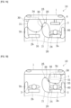
FIG. 1A] FIG. 1A is a diagram viewed from above in the vehicle illustrating the airbag system according to an embodiment with a cushion of a side airbag and a cushion of a front airbag for a front passenger's seat completely inflated and deployed respectively. - [
FIG. 1B] FIG. 1B is a diagram similar toFIG. 1A illustrating a variation with a front airbag for a driver deployed. - [
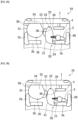
FIG. 2] FIG. 2 is a diagram viewed from the side of the vehicle illustrating the airbag system according to the embodiment with the cushion of the side airbag and the cushion of the front airbag for a front passenger's seat completely inflated and deployed respectively. - [
FIG. 3A] FIG. 3A is a diagram viewed from above in the vehicle illustrating the airbag system according to a first variation of the embodiment with a cushion of a side airbag and a cushion of a front airbag for a front passenger's seat completely inflated and deployed respectively. - [
FIG. 3B] FIG. 3B is a view similar toFIG. 3A illustrating a second variation in which the second sub-chamber is provided in the front airbag for the front passenger's seat. - [
FIG. 4] FIG. 4 is a diagram describing a movement of an occupant at the time of a side collision according to an embodiment including neither a first sub-chamber nor a second sub-chamber. - [
FIG. 5] FIGS. 5A and 5B are diagrams viewed from above in the vehicle illustrating the airbag system according to a third variation of the embodiment with a cushion of a side airbag and a cushion of a front airbag for a front passenger's seat completely inflated and deployed respectively. - [
FIG. 6] FIGS. 6A and 6B are diagrams viewed from above in the vehicle illustrating the airbag system according to a fourth variation of the embodiment with a cushion of a side airbag and a cushion of a front airbag for a front passenger's seat completely inflated and deployed respectively. - [
FIG. 7] FIGS. 7A and 7B are views similar toFIG. 5 illustrating a variation combining the second variation and the third variation. - Embodiments of the present invention are described below in detail with reference to the drawings. Note that the following embodiments are examples of the present invention, and are not intended to limit the scope of the present invention, the application thereof, or the uses thereof.
- An example of the definition of the term "occupant" in the present invention is an occupant in accordance with a frontal collision test dummy (Hybrid III AM50; human body dummy for frontal collision test set forth in specification [49CFR Part 572 Subpart E and O] of NHTSA [National Highway Traffic Safety Administration]) with a physique equivalent to the average male in the United States; having an approximate size of 175 cm height, 88 cm sitting height, and 78 kg weight. However, the present invention can also be applied for other anthropomorphic test dummies.
- Note that in the present specification, the terms "upper" and "upper side" refer to a head direction of an
occupant 3 seated in a regular position in a seat, and "lower" and "lower side" refer to a foot direction of theoccupant 3. It should be noted that the "regular position" refers to a position in a center, in the left-right direction, of a seat cushion of the seat with the back of theoccupant 3 in contact with abackrest portion 7 from above and below. In addition, the terms "front" and "front side" refer to a forward direction of theoccupant 3 seated in a seat in the regular position, and "rear" and "rear side" refer to a backward direction of theoccupant 3. Moreover, the terms "left" and "left side" refer to a left-hand direction of theoccupant 3 seated in a seat in the regular position, and "right" and "right side" refer to the right-hand direction of theoccupant 3. Furthermore, the "width direction(s)" of the vehicle and the "vehicle width direction(s)" may stand for the same direction(s) as the "right" and "left" direction(s). - As illustrated in
FIG. 1A , the present embodiment is anairbag system 10 that includes: at least aside airbag 20 and afront airbag 30 for a front passenger's seat; and acontrol device 40 for controlling, among other things, the timing of starting the inflation and deployment ofcushions airbag system 10 of the present embodiment further includes: a driver'sseat side airbag 60, which protects the near side of theoccupant 3 seated in the driver'sseat 2a; and a front passenger'sseat side airbag 70, which protects the near side of the occupant seated in the front passenger'sseat 2b. Asteering wheel 4 is provided in front of the driver'sseat 2a. Of the two seats arranged side by side in the vehicle width direction in thevehicle 1, the driver'sseat 2a, specifically thebackrest portion 3 thereof accommodates theside airbag 20 in a side portion on the far side thereof. Thefront airbag 30 for the front passenger's seat is accommodated in an instrument panel 5 of thevehicle 1. Of those seats arranged in the vehicle width direction, the driver'sseat 2a corresponds to one seat in the vehicle and the front passenger'sseat 2b corresponds to the other seat, which is provided adjacent to the driver'sseat 2a. The front passenger'sseat front airbag 30 corresponds to a front airbag. Before describing theairbag system 10, the configuration of the seat will be described below. - As illustrated in
FIG. 2 , the driver'sseat 2a includes aseat cushion 6 and abackrest portion 7. The upper end portion of thebackrest portion 7 has aheadrest 8 attached via rod-shapedsupport members 8a. Theheadrest 8 may be formed integrally with thebackrest portion 7 without providing thesupport members 8a. - The
seat cushion 6 has a pad provided on the upper side of a seat pan, and the pad is covered with a cover material. In thebackrest portion 7, a pad is provided on the front side of the seat frame, and the pad is covered with a cover material. - The
cushion 21 of theside airbag 20 placed in a flat state is rolled up or folded into a bellows shape to convert it to an accommodation form that is adapted to be accommodated in the driver'sseat 2a. Thecushion 21 in the accommodated state is accommodated along a side portion of the seat frame of the driver'sseat 2a. The location where thecushion 21 is accommodated is the inside of a side support portion provided in the far-side side portion of thebackrest portion 3. - The
side airbag 20 is an airbag device for protecting the far-side side portion of theoccupant 3 seated on the driver'sseat 2a. Theside airbag 20 includes acushion 21 and aninflator 24. At the time of a side collision of the vehicle, theside airbag 20 is inflated and deployed toward the front side of the vehicle at a side portion of the driver'sseat 2a located on the center side in the vehicle width direction. - The inflator 24 is a device for injecting gas into the
cushion 21 for inflation. In theside airbag 20, atubular inflator 24 is disposed in thecushion 21 and injects gas into thecushion 21 through ahole 24a formed in the outer side surface of theinflator 24. The inflator 24 is disposed in an accommodation portion provided in thecushion 21. - The
cushion 21 has a required length in the up-down direction and the front-rear direction, which make it possible to restrain a side of theoccupant 3, for example, a side of: a head portion, a shoulder portion, an upper arm portion, a chest portion, a waist portion, or an abdomen portion. Thecushion 21 is formed in a bag shape by sewing together the outer periphery portions of 2 pierces of base fabric panels formed in identical shapes so as to increase thickness in the left-right directions. Alternatively, a required number of base fabric panels each having a required shape may be prepared in advance, and a bag body may be formed by sewing at predetermined positions. - Two stud bolts (not illustrated) are attached to the outer side surface located on the side opposite the
hole 24a of theinflator 24. The two stud bolts protrude, at appropriate spacing in the longitudinal direction, from that outer side surface of theinflator 24. Using these stud bolts, theinflator 24 is secured to the seat frame. In addition, fixing the accommodation portion of the inflator to the seat frame also fixes thecushion 21 to the seat frame. A fastener may be used as a means for attaching thecushion 21 to the side frame. - The
front airbag 30 for the front passenger's seat includes: acushion 31 that is inflated and deployed toward theseat 2b for the front passenger's seat; aninflater 34 that injects inflation gas for inflating thecushion 31; and anaccommodation case 33 which accommodates thecushion 31 and which is attached to anaccommodation portion 5a. - As illustrated in
FIG. 2 , thefront airbag 30 for a front passenger's seat is disposed in theaccommodation portion 5a provided in a front passenger's seat panel of the instrument panel 5. The front passenger's seat panel is a panel disposed in front of the front passenger's seat. Theairbag cushion 31 is folded or rolled into a small, folded accommodation form for placement in theaccommodation portion 5a. - A disk-shaped
inflator 34 is disposed in thecushion 31. The inflator 34 is a gas generator, and is actuated by a signal received from acontrol device 40 connected to asensor 41 for detecting a collision. Once actuated, the inflator 34 supplies inflation gas to thecushion 31. - In a non-inflated state before the
cushion 31 is inflated and deployed, the opening of theaccommodation portion 5a is closed by a door portion provided in the instrument panel 5. Thefront window screen 9 is a plate member provided on a front window of the vehicle, and is provided so as to be inclined toward the vehicle interior with respect to the upper surface of the instrument panel 5. - In the conventional airbag system, the
front airbag 30 for the front passenger's seat is configured such that the inflator 34 injects the inflation gas into thecushion 31 only when an impact is applied from the front side of the vehicle. The inflated and deployedcushion 31 is used for the purpose of restraining, only from the front side, theoccupant 3 seated on the front passenger'sseat 2b. - On the other hand, the
front airbag 30 for a front passenger's seat in theairbag system 10 of the present embodiment is used for a greatly different purpose. In the following description, the characteristic configuration and effects of theairbag system 10 will be described with reference toFIG. 1A andFIG. 2 . - The
airbag system 10 includes: aside airbag 20 which is located on a side portion on the vehicle center side of the driver'sseat 2a of thevehicle 1 and which is inflated and deployed toward the front side of the vehicle; afront airbag 30 for the front passenger's seat that is inflated and deployed on the vehicle's front side of the front passenger'sseat 2b; and acontrol device 40 that, in a side collision, causes thefront airbag 30 for the front passenger's seat to be inflated and deployed together with theside airbag 20. Thus, although in the related art, thefront airbag 30 for a front passenger's seat has been inflated and deployed only at the time of a head-on collision, theairbag system 10 can inflate and deploy thefront airbag 30 for a front passenger's seat also at the time of a side collision. As illustrated inFIG. 2 , when thecushion 21 of theside airbag 20 inflated and deployed and thecushion 31 of thefront airbag 30 for the front passenger's seat inflated and deployed are viewed from a lateral direction of thevehicle 1 that is perpendicular to the front-rear direction, the vehicle's front-side end portion 25 of thecushion 21 of theside airbag 20 is located on a further front side of the vehicle than the vehicle's rear-side end portion 35 of thecushion 31 of thefront airbag 30 for the front passenger's seat . - To put it differently, as shown in
FIG. 2 , theairbag system 10 has an overlappingportion 11 where thecushion 21 of theside airbag 20 inflated and deployed and thecushion 31 of thefront airbag 30 for the front passenger's seat inflated and deployed overlap each other when theside airbag 20 and thefront airbag 30 for the front passenger's seat are perspectively seen from a lateral-side position with respect to the front-rear direction of thevehicle 1. The overlappingportion 11 is formed between the vehicle's front-side end portion 25 of theside airbag 20 and the vehicle's rear-side end portion 35 of thefront airbag 30 for the front passenger's seat. - To be more specific, when the
airbag system 10 is in a state in which theside airbag 20 and thefront airbag 30 for the front passenger's seat are completely inflated and deployed respectively, as shown inFIG. 1A , thecushion 21 of theside airbag 20 has afirst contact region 26 that is in contact with thefront airbag 30 for the front passenger's seat, and thecushion 31 of thefront airbag 30 for the front passenger's seat has asecond contact region 36 that is in contact with the side airbag. - In general, a rotation of the leading end portion of the cushion of the side airbag causes the cushion to swing so as to avoid the occupant moving in the vehicle width direction, which makes it difficult to sufficiently and appropriately protect the occupant. In addition, an inclination of the cushion toward the front passenger's seat side makes it impossible to secure a portion that accurately receives the occupant, which in turn makes it difficult to sufficiently and appropriately protect the occupant.
- To deal with such problems as described above, in the
airbag system 10, when a side collision, an oblique collision, or the like occurs and thesensor 41 detects the collision, thecontrol unit 40 that receives a signal from thesensor 41 actuates not only theinflator 24 of theside airbag 20 but also theinflator 34 of thefront airbag 30 for the front passenger's seat. The inflator 24 ejects gas into thecushion 21 to inflate and deploy thecushion 21, and the inflator 34 ejects gas into thecushion 31 to inflate and deploy thecushion 31. - At this time, in the
airbag system 10, the vehicle's front-side end portion 25 of theside airbag 20 is configured to be positioned on the front side, in the front-rear direction of thevehicle 1, of the vehicle's rear-side end portion 35 of thefront airbag 30 for the front passenger's seat, and theairbag system 10 has the overlappingportion 11 where theside airbag 20 and thefront airbag 30 for the front passenger's seat overlap each other. - In the
airbag system 10, the vehicle's front-side end portion 25 of thecushion 21 is positioned on the further front side of thevehicle 1 than the vehicle's rear-side end portion 35 of thecushion 31, or the overlappingportion 11 is present. Hence, thefront airbag 30 for the front passenger's seat can be inflated and deployed when a side collision occurs, and the inflated and deployedfront airbag 30 for the front passenger's seat can be brought into contact with theside airbag 20. Specifically, theside airbag 20 and thefront airbag 30 for the front passenger's seat have afirst contact region 26 and asecond contact region 36, respectively. - Thus, in the
airbag system 10, thecushion 31 of thefront airbag 30 for the front passenger's seat used as a support can prevent the vehicle's front side of thecushion 21 of the inflated and deployedside airbag 20 from horizontally rotating toward the front passenger'sseat 2b. In addition, using thecushion 31 as a support can prevent the upper side of the inflated and deployedcushion 21 from tilting toward the front passenger'sseat 2b. Therefore, theairbag system 10 can secure a portion for accurately receiving theoccupant 3, and thus can improve the performance of restraining theoccupant 3. - The front passenger's
seat 2b may be either occupied by an occupant or unoccupied with no one seated thereon. In either case, theairbag system 10 allows thecushion 21 of theside airbag 20 to be inflated and deployed. Theairbag system 10 can reliably protect theoccupant 3 seated on the driver'sseat 2a from an impact at the time of a side collision, an oblique collision, or the like, regardless of the presence or absence of an occupant on the front passenger'sseat 2b. - In addition, when a side collision of the
vehicle 1 occurs on the side of the front passenger'sseat 2b, the occupant moves to the side where the collision occurs in the initial stage of the collision due to inertial forces, and then moves to the opposite side due to the impact force of the collision. In theairbag system 10, when thecushion 21 of theside airbag 20 is inflated and deployed, the occupant seated on the front passenger'sseat 2b can also be restrained from moving toward the center in the vehicle width direction and from moving obliquely forward to the center in the vehicle width direction. - In the
airbag system 10, when a collision occurs from the front side of thevehicle 1 with an occupant seated on the front passenger'sseat 2b, thecushion 31 of thefront airbag 30 for the front passenger's seat is inflated and deployed so as to restrain the head portion, the chest portion, the abdominal portion, and the like of the occupant seated on the front passenger'sseat 2b from the front side, as in the conventional airbag system. Thefront airbag 30 for the front passenger's seat also functions to prevent the occupant seated in the front passenger'sseat 2b from colliding with theinstrument panel 7 or thefront window screen 9 as in the conventional airbag system. - As shown in
FIG. 3A , in theairbag system 10 of the present variation, thecushion 21 of theside airbag 20 includes: a firstmain chamber 22 that is inflated and deployed toward the front side of thevehicle 1; and a first sub-chamber 23 that is inflated and deployed so as to protrude from the firstmain chamber 22 toward the center in the vehicle's width direction (toward thefront airbag 30 for the front passenger's seat). In addition, afirst contact region 26 is present on thefirst sub-chamber 23. Thefirst sub-chamber 23 of the present variation is provided in the overlappingportion 11 illustrated inFIG. 2 (i.e., a portion where thecushion 21 of theside airbag 20 and thecushion 31 of thefront airbag 30 for the front passenger's seat overlap each other when perspectively seen from a lateral side with respect to the front-rear direction of the vehicle 1). - The
first sub-chamber 23 has a smaller chamber capacity than the firstmain chamber 22. Thefirst sub-chamber 23 is formed so as to protrude obliquely toward the front side of the front passenger'sseat 2b. Thefirst sub-chamber 23 of the present variation is a separate body from the firstmain chamber 22, and is attached to the firstmain chamber 22 by sewing. Thefirst sub-chamber 23 communicates with the firstmain chamber 22 via a vent hole formed in the firstmain chamber 22. - In the present variation, in the event of a side collision, the
inflator 21 receives a signal from the sensor and ejects gas through the hole 21a formed in the outer side surface of the inflator 21 into the firstmain chamber 22, thereby inflating and deploying the firstmain chamber 22. After the firstmain chamber 22 is inflated and deployed, gas flows into thefirst sub-chamber 23 through the vent hole, causing thefirst sub-chamber 23 to be inflated and deployed. - The number of vent holes and the size of each hole may be designed by taking into consideration the timing of inflating and deploying the
first sub-chamber 23. If the total opening area of the vent holes is made sufficiently large, gas can be quickly supplied to thefirst sub-chamber 23 almost simultaneously with the inflation and the deployment of the firstmain chamber 22, allowing thefirst sub-chamber 23 to be inflated quickly. Depending on design requirements, the total opening area of the vent holes can be adjusted to be slightly smaller, thereby creating a required time lag between the inflation and the deployment of the firstmain chamber 22 and the inflation and deployment of thefirst sub-chamber 23. - When the configuration of the present variation is compared with another configuration of the embodiment including no first sub-chamber 23 (
FIG. 4 ), thefirst sub-chamber 23 is inflated so as to protrude toward thefront airbag 30 for the front passenger's seat, and thus the space between theside airbag 20 inflated and deployed and thefront airbag 30 for the front passenger's seat inflated and deployed is filled with thefirst sub-chamber 23, and thecushion 31 of thefront airbag 30 for the front passenger's seat can easily support thecushion 21 of theside airbag 20. In addition, in the present variation, a side collision moves theoccupant 3 toward the center in the vehicle width direction by a reduced amount (cf. comparison betweenFIGS. 4 and3A ). - In the present variation, since the support is stabilized by the first sub-chamber 23 protruding toward the front side of the front passenger's
seat 2b, it is possible to further enhance the effect of preventing the rotation of the leading end portion of thecushion 21 and the effect of preventing the inclination of thecushion 21. - As shown in
FIG. 3B , in theairbag system 10 of the present variation, thecushion 31 of thefront airbag 30 for the front passenger's seat is configured to include: the secondmain chamber 32 that is inflated and deployed toward the rear side of thevehicle 1; and asecond sub-chamber 33 that is inflated and deployed so as to protrude from the secondmain chamber 32 toward the center in the vehicle's width direction (toward the side of the side airbag 20). Thesecond sub-chamber 33 of the present variation is provided in the overlappingportion 11 in which thecushion 21 of theside airbag 20 and thecushion 31 of thefront airbag 30 for the front passenger's seat overlap each other when perspectively seen from a lateral side with respect to the front-rear direction of thevehicle 1. - Also in the case where the
second sub-chamber 33 is provided for thefront airbag 30 for the front passenger's seat, the space between theside airbag 20 and thefront airbag 30 for the front passenger's seat is filled with thesecond sub-chamber 33, and thecushion 31 of thefront airbag 30 for the front passenger's seat easily supports thecushion 21 of theside airbag 20. Therefore, it is possible to further enhance the effect of preventing thecushion 21 from swinging and tilting when the occupant is restrained. - As shown in
FIG. 5 , in the present variation, thecushion 21 of theside airbag 20 is provided with a first high-friction portion 27 having a larger friction coefficient than the surface portion of the base fabric panel constituting thecushion 21 of theside airbag 20, and the first high-friction portion 27 includes thefirst contact region 26. - Accordingly, in the present variation, the first
high friction portion 27 plays a role of a non-slip device. Hence, once thecushion 21 of theside airbag 20 inflated and deployed and thecushion 31 of thefront airbag 30 for a front passenger's seat inflated and deployed are in a contact state, slippage can be prevented from occurring. Therefore, it is easier to maintain the state in which thecushion 21 of theside airbag 20 and thecushion 31 of thefront airbag 30 for the front passenger's seat are in contact with each other, which enhances the protection performance for theoccupant 3. - In the present variation, a means for increasing the friction coefficient of the first high-
friction portion 27 can be implemented by attaching a patch. For example, of the two base fabric panels forming thecushion 21, the base fabric panel on the side in contact with thecushion 31, specifically, the surface thereof, is provided with a patch having a friction coefficient larger than that of the base fabric panel. The patch is sewn and thus attached to the surface mentioned above. This sewing may be performed along the end sides of the patch, for example, in the vicinity of the upper side and the lower side of the patch. Too large a patch may provide an obstacle to the inflation and deployment of thecushion 21 whereas too small a patch may provide an obstacle to an expectation of an appropriate non-slip effect. Therefore, the size of the patch may be appropriately determined within a range that can prevent these problems from occurring. - In the present variation, a means for increasing the friction coefficient of the first
high friction portion 27 can also be implemented by applying a resin coating. For example, of the two base fabric panels forming thecushion 21, the base fabric panel on the side in contact with thecushion 31, specifically, the surface thereof, is coated with a resin having a friction coefficient larger than that of the base fabric panel. Also in this case, the size of the area to be coated with the resin may be determined based on the same criteria as described above. - As shown in
FIG. 6 , in the present variation, thecushion 31 of thefront airbag 30 for the front passenger's seat is provided with a second high-friction portion 37 having a larger friction coefficient than the surface portion of the base fabric panel constituting thecushion 31 of thefront airbag 30 for a front passenger's seat, and the second high-friction portion 37 includes a second contact region 66. - Also in the present variation, the second
high friction portion 37 plays a role of a non-slip device. Hence, once thecushion 21 of theside airbag 20 inflated and deployed and thecushion 31 of thefront airbag 30 for a front passenger's seat inflated and deployed are in a contact state, slippage can be prevented from occurring. Therefore, also in the present variation, it is easier to maintain the state in which thecushion 21 of theside airbag 20 and thecushion 31 of thefront airbag 30 for the front passenger's seat are in contact with each other, which enhances the protection performance for theoccupant 3 as in the second variation. - Also in the present variation, a means for increasing the friction coefficient in the first
high friction portion 27 can also be implemented by attaching a patch or applying a resin coating, for example. - In the above-described embodiment, the front airbag may be a front airbag for the driver. To put it differently, the present invention may be configured to provide a side airbag in the side portion on the center side, in the vehicle's width direction, of the front passenger's
seat 2b, and also provide a front airbag in front of the driver'sseat 2a. In this case, when the cushion of the side airbag is inflated and deployed, the driver's front airbag serving as a support can suppress the vehicle front side of the cushion from rotating toward the driver'sseat 2a and can also suppress the upper side of the cushion from tilting toward the driver'sseat 2a. - In the above-described embodiment, the front airbag that supports the
side airbag 20 provided in the driver'sseat 2a may be a driver's front airbag. To put it differently, as shown inFIG. 1B , theairbag system 10 of the present invention may be configured to include: aside airbag 20 that is inflated and deployed toward the front side of the vehicle at a side portion located on the center side, in the vehicle width direction, the driver'sseat 2a; and a driver'sfront airbag 50 that is inflated and deployed in front of the driver'sseat 2a. In this case, at the time of a side collision of the vehicle, thecontrol device 40 inflates and deploys the driver'sfront airbag 50 along with the inflation and deployment of theside airbag 20. The driver'sfront airbag 50 is disposed in an accommodation portion of a driver's seat panel located within the instrument panel 5 and disposed in front of the driver'sseat 2a. The driver'sfront airbag 50 includes: acushion 51, which is inflated and deployed towards the driver'sseat 2a; and an inflator 54, which ejects inflating gas to inflate thecushion 51. - Also in the
airbag system 10 of the present variation, when theside airbag 20 inflated and deployed and the driver'sfront airbag 50 inflated and deployed are viewed from a lateral direction that is perpendicular to the front-rear direction of the vehicle, the vehicle's front-side end portion 25 of theside airbag 20 is positioned further toward the front side of the vehicle than the vehicle's rear-side end portion 55 of the driver'sfront airbag 50. In addition, theairbag system 10 of the present variation also has the overlappingportion 11 where theside airbag 20 and the driver'sfront airbag 50 overlap each other when viewed from a lateral direction that is perpendicular to the front-rear direction of the vehicle. Thus, the driver'sfront airbag 50 can be inflated and deployed at the time of a side collision, and the driver'sfront airbag 50 inflated and deployed can be brought into contact with theside airbag 20. Specifically, theside airbag 20 and the driver'sfront airbag 50 have afirst contact region 26 and athird contact region 56, respectively. As in the case of the above-described embodiment, in the present variation, the driver'sfront airbag 50 serving as a support can suppress thecushion 21 of theside airbag 20 from swinging in the horizontal directions and can also suppress the upper side of the cushion from tilting. - In the above-described embodiment, the
first sub-chamber 23 of thecushion 21 described in the first variation may be formed integrally with the firstmain chamber 22. Also, thesecond sub-chamber 33 of thecushion 31 described in the second variation may be provided as a separate body from the secondmain chamber 32 but may be sewn to the secondmain chamber 32, or thesecond sub-chamber 33 may be integrally formed with the secondmain chamber 32. - In the embodiment described above, the configuration described in the third variation and the configuration described in the fourth variation may be combined together. To put it differently, as illustrated in
FIG. 7 , thecushion 21 of theside airbag 20 may be provided with the first high-friction portion 27, and thecushion 31 of thefront airbag 30 for the front passenger's seat may be provided with the second high-friction portion 37. In this case, the first high-friction portion 27 includes thefirst contact region 26, and the second high-friction portion 37 includes the second contact region 66. In the present variation, since the first high-friction portion 27 and the second high-friction portion 37 both having large friction coefficients are in contact with each other, the effect of preventing slippage between thecushion 21 and thecushion 31 is further enhanced. - In the embodiment described above, the
cushion 21 of theside airbag 20 and thecushion 31 of thefront airbag 30 for the front passenger's seat are not limited to cushions each formed by joining a suitable number of base fabric panels by sewing or the like, but may be formed using a so-called "one-piece weaving" technique. - In the above-described embodiment, the dimensions of the
cushion 21 of theside airbag 20 and thecushion 31 of thefront airbag 30 for the front passenger's seat in the up-down direction, the front-rear direction, and the left-right direction are not limited to those illustrated in the drawings. The sizes and shapes of thecushion 21 and thecushion 31 may be appropriately adjusted according to the shapes and installation positions of the driver'sseat 2a and the front passenger'sseat 2b, the range in which protection of the occupant is required, and the like. - The configuration of the present invention is not dependent on a specific vehicle type, and can be applied to any vehicle.
-
- 1. Vehicle
- 2a. Driver's seat
- 2b. Front passenger's seat
- 3. Occupant
- 10. Airbag system
- 11. Overlapping portion
- 20. Side airbag
- 21. Cushion
- 22. First main chamber
- 23. First sub-chamber
- 24. Inflator
- 25. Vehicle's front-side end portion of side airbag
- 26. First contact region
- 27. First high friction portion
- 30. Front airbag for front passenger's seat
- 31. Cushion
- 32. Second main chamber
- 33. Second sub-chamber
- 34. Inflator
- 35. Vehicle's rear-side end portion of front airbag for front passenger's seat
- 36. Second contact region
- 37. Second high friction portion
- 40. Control device
- 50. Front airbag for driver's seat
- 51. Cushion
- 54. Inflator
- 55. Vehicle's rear-side end portion of front airbag for driver's seat
- 56. Third contact region
Claims (10)
- An airbag system comprising:a side airbag inflated and deployed toward a front side of a vehicle at a side portion on a vehicle width direction center side of one seat of the vehicle;a front airbag inflated and deployed at a vehicle's front side of the other seat provided adjacent to the one seat of the vehicle in a vehicle width direction; anda control device causing the front airbag to be inflated and deployed together with the side airbag at the time of a side collision of the vehicle,wherein when the side airbag inflated and deployed and the front airbag inflated and deployed are viewed from a lateral direction perpendicular to a front-rear direction of the vehicle, a vehicle's front-side end portion of the side airbag is positioned further toward the front side of the vehicle than a vehicle's rear-side end portion of the front airbag.
- An airbag system comprising:a side airbag inflated and deployed toward a front side of a vehicle at a side portion on a vehicle width direction center side of one seat of the vehicle;a front airbag inflated and deployed at a vehicle's front side of the one seat of the vehicle; anda control device causing the front airbag to be inflated and deployed together with the side airbag at the time of a side collision of the vehicle,wherein when the side airbag inflated and deployed and the front airbag inflated and deployed are viewed from a lateral direction perpendicular to a front-rear direction of the vehicle, a vehicle's front-side end portion of the side airbag is positioned further toward the front side of the vehicle than a vehicle's rear-side end portion of the front airbag.
- The airbag system according to claim 1 or 2, wherein when the side airbag inflated and deployed and the front airbag inflated and deployed are perspectively viewed from a lateral direction perpendicular to a front-rear direction of the vehicle, the side airbag and the front airbag have an overlapping portion at which the side airbag and the front airbag overlap each other.
- The airbag system according to claim 1 or 2, wherein in an inflation completed state in which the side airbag and the front airbag are completely inflated and deployed respectively, the side airbag has a first contact region in contact with the front airbag, and the front airbag has a second contact region in contact with the side airbag.
- The airbag system according to claim 3, wherein the side airbag includes: a first main chamber inflated and deployed toward a vehicle's front side; and a first sub-chamber inflated and deployed so as to protrude from the first main chamber toward a center side in a vehicle's width direction, wherein the first sub-chamber is provided in the overlapping portion.
- The airbag system according to claim 3, wherein the front airbag includes: a second main chamber inflated and deployed toward a vehicle's rear side; and a second sub-chamber inflated and deployed so as to protrude from the second main chamber toward a center side in a vehicle's width direction, wherein the second sub-chamber is provided in the overlapping portion.
- The airbag system according to claim 4, wherein the side airbag is provided with a first high-friction portion having a larger friction coefficient than a surface portion of a base fabric panel constituting the side airbag, wherein the first high-friction portion includes the first contact region.
- The airbag system according to claim 4, wherein the front airbag is provided with a second high-friction portion having a larger friction coefficient than a surface portion of a base fabric panel constituting the front airbag, and wherein the second high-friction portion includes the second contact region.
- The airbag system according to claim 1 or 2, wherein the front airbag is a front airbag for a front passenger's seat.
- The airbag system according to claim 1 or 2, wherein the front airbag is a driver's front airbag.
Applications Claiming Priority (2)
| Application Number | Priority Date | Filing Date | Title |
|---|---|---|---|
| JP2022144264 | 2022-09-12 | ||
| PCT/JP2023/032069 WO2024057972A1 (en) | 2022-09-12 | 2023-09-01 | Airbag system |
Publications (2)
| Publication Number | Publication Date |
|---|---|
| EP4570600A1 true EP4570600A1 (en) | 2025-06-18 |
| EP4570600A4 EP4570600A4 (en) | 2026-03-25 |
Family
ID=90275128
Family Applications (1)
| Application Number | Title | Priority Date | Filing Date |
|---|---|---|---|
| EP23865327.3A Pending EP4570600A4 (en) | 2022-09-12 | 2023-09-01 | AIRBAG SYSTEM |
Country Status (6)
| Country | Link |
|---|---|
| US (1) | US20260109311A1 (en) |
| EP (1) | EP4570600A4 (en) |
| JP (1) | JP7775493B2 (en) |
| KR (1) | KR20250065613A (en) |
| CN (1) | CN119855744A (en) |
| WO (1) | WO2024057972A1 (en) |
Family Cites Families (19)
| Publication number | Priority date | Publication date | Assignee | Title |
|---|---|---|---|---|
| JPH0769149A (en) | 1993-09-02 | 1995-03-14 | Takata Kk | Passenger airbag device |
| JP4894803B2 (en) | 2008-03-28 | 2012-03-14 | 豊田合成株式会社 | Crew protection device |
| DE102010027401B4 (en) * | 2010-07-15 | 2022-05-12 | Autoliv Development Ab | Side gas bag with lateral support |
| JP6056695B2 (en) | 2013-07-17 | 2017-01-11 | トヨタ自動車株式会社 | Center airbag device for vehicle and occupant protection device for vehicle |
| JP5949737B2 (en) | 2013-12-06 | 2016-07-13 | トヨタ自動車株式会社 | Far-side airbag device for vehicles |
| JP2015185946A (en) | 2014-03-20 | 2015-10-22 | キヤノン株式会社 | Antenna device |
| US9561774B2 (en) * | 2014-04-24 | 2017-02-07 | Ford Global Technologies, Llc | Winged driver airbag |
| JP6007213B2 (en) | 2014-08-06 | 2016-10-12 | 富士重工業株式会社 | Vehicle occupant protection device |
| JP2016040155A (en) * | 2014-08-12 | 2016-03-24 | 豊田合成株式会社 | Airbag device for front passenger seat |
| US10011243B2 (en) * | 2016-01-29 | 2018-07-03 | Ford Global Technologies, Llc | Passenger airbag having head orienting extension and depression |
| JP6565765B2 (en) | 2016-03-30 | 2019-08-28 | 豊田合成株式会社 | Airbag device for passenger seat |
| JP2017222185A (en) * | 2016-06-13 | 2017-12-21 | トヨタ自動車株式会社 | Vehicle airbag device |
| US10214174B2 (en) * | 2017-01-30 | 2019-02-26 | Toyoda Gosei Co., Ltd. | Vehicle airbag apparatus |
| US10407015B2 (en) * | 2017-06-27 | 2019-09-10 | Ford Global Technologies, Llc | Restraint system |
| US10464519B2 (en) * | 2017-10-18 | 2019-11-05 | Trw Vehicle Safety Systems Inc. | Airbag for oblique crash protection |
| US11731576B2 (en) * | 2018-10-24 | 2023-08-22 | Autoliv Development Ab | Side airbag device |
| JP2020090258A (en) * | 2018-12-07 | 2020-06-11 | トヨタ自動車株式会社 | Air bag device |
| JP7180456B2 (en) * | 2019-03-06 | 2022-11-30 | トヨタ自動車株式会社 | Seat structure with far side airbag device |
| JP2021062818A (en) | 2019-10-16 | 2021-04-22 | トヨタ自動車株式会社 | Vehicle front center airbag device |
-
2023
- 2023-09-01 JP JP2024546864A patent/JP7775493B2/en active Active
- 2023-09-01 US US19/111,210 patent/US20260109311A1/en active Pending
- 2023-09-01 KR KR1020257008281A patent/KR20250065613A/en active Pending
- 2023-09-01 CN CN202380064880.6A patent/CN119855744A/en active Pending
- 2023-09-01 EP EP23865327.3A patent/EP4570600A4/en active Pending
- 2023-09-01 WO PCT/JP2023/032069 patent/WO2024057972A1/en not_active Ceased
Also Published As
| Publication number | Publication date |
|---|---|
| EP4570600A4 (en) | 2026-03-25 |
| JP7775493B2 (en) | 2025-11-25 |
| CN119855744A (en) | 2025-04-18 |
| JPWO2024057972A1 (en) | 2024-03-21 |
| US20260109311A1 (en) | 2026-04-23 |
| KR20250065613A (en) | 2025-05-13 |
| WO2024057972A1 (en) | 2024-03-21 |
Similar Documents
| Publication | Publication Date | Title |
|---|---|---|
| EP3228505B1 (en) | Occupant protection apparatus | |
| US9533651B1 (en) | Occupant protection device | |
| RU2673409C1 (en) | Device for protecting passenger | |
| US12109967B2 (en) | Airbag device | |
| EP3888980B1 (en) | Side airbag device | |
| US20130341975A1 (en) | Airbag arrangement for seats arranged in tandem | |
| US11752965B2 (en) | Side airbag device and method for manufacturing side airbag device | |
| US9039035B1 (en) | Deployable airbag arrangement for rear seat occupant | |
| JP2021526103A (en) | Airbag device for vehicles | |
| US20130106079A1 (en) | Airbag arrangement for bulkhead seats | |
| JP7542641B2 (en) | Airbag device | |
| US11498509B2 (en) | Roof mounted passenger airbag | |
| US12447920B2 (en) | Vehicular side airbag device | |
| CN114763120A (en) | Occupant restraint system | |
| CN116198446A (en) | Distal balloon device | |
| CN110871765B (en) | Airbag device | |
| US11938882B2 (en) | Side airbag packaged in side of seat | |
| KR102729838B1 (en) | Airbag devices and vehicle seats | |
| US20260109311A1 (en) | Airbag system | |
| WO2025100167A1 (en) | Airbag device | |
| WO2024095697A1 (en) | Occupant restraint apparatus | |
| JP7555477B2 (en) | Airbag device | |
| JP7441961B2 (en) | air bag device | |
| KR20240095451A (en) | Vehicle side airbag device | |
| KR102626944B1 (en) | Far side airbag apparatus for vehicle and folding method thereof |
Legal Events
| Date | Code | Title | Description |
|---|---|---|---|
| STAA | Information on the status of an ep patent application or granted ep patent |
Free format text: STATUS: THE INTERNATIONAL PUBLICATION HAS BEEN MADE |
|
| PUAI | Public reference made under article 153(3) epc to a published international application that has entered the european phase |
Free format text: ORIGINAL CODE: 0009012 |
|
| STAA | Information on the status of an ep patent application or granted ep patent |
Free format text: STATUS: REQUEST FOR EXAMINATION WAS MADE |
|
| 17P | Request for examination filed |
Effective date: 20250313 |
|
| AK | Designated contracting states |
Kind code of ref document: A1 Designated state(s): AL AT BE BG CH CY CZ DE DK EE ES FI FR GB GR HR HU IE IS IT LI LT LU LV MC ME MK MT NL NO PL PT RO RS SE SI SK SM TR |
|
| DAV | Request for validation of the european patent (deleted) | ||
| DAX | Request for extension of the european patent (deleted) | ||
| A4 | Supplementary search report drawn up and despatched |
Effective date: 20260220 |
|
| RIC1 | Information provided on ipc code assigned before grant |
Ipc: B60R 21/231 20110101AFI20260216BHEP Ipc: B60R 21/203 20060101ALI20260216BHEP Ipc: B60R 21/205 20110101ALI20260216BHEP Ipc: B60R 21/207 20060101ALI20260216BHEP |