EP4570584A1 - Battery self-heating control system and control method, and electric transportation means - Google Patents
Battery self-heating control system and control method, and electric transportation means Download PDFInfo
- Publication number
- EP4570584A1 EP4570584A1 EP23858695.2A EP23858695A EP4570584A1 EP 4570584 A1 EP4570584 A1 EP 4570584A1 EP 23858695 A EP23858695 A EP 23858695A EP 4570584 A1 EP4570584 A1 EP 4570584A1
- Authority
- EP
- European Patent Office
- Prior art keywords
- battery group
- switch assembly
- battery
- winding
- capacitor
- Prior art date
- Legal status (The legal status is an assumption and is not a legal conclusion. Google has not performed a legal analysis and makes no representation as to the accuracy of the status listed.)
- Pending
Links
Images



Classifications
-
- B—PERFORMING OPERATIONS; TRANSPORTING
- B60—VEHICLES IN GENERAL
- B60L—PROPULSION OF ELECTRICALLY-PROPELLED VEHICLES; SUPPLYING ELECTRIC POWER FOR AUXILIARY EQUIPMENT OF ELECTRICALLY-PROPELLED VEHICLES; ELECTRODYNAMIC BRAKE SYSTEMS FOR VEHICLES IN GENERAL; MAGNETIC SUSPENSION OR LEVITATION FOR VEHICLES; MONITORING OPERATING VARIABLES OF ELECTRICALLY-PROPELLED VEHICLES; ELECTRIC SAFETY DEVICES FOR ELECTRICALLY-PROPELLED VEHICLES
- B60L15/00—Methods, circuits, or devices for controlling the traction-motor speed of electrically-propelled vehicles
- B60L15/007—Physical arrangements or structures of drive train converters specially adapted for the propulsion motors of electric vehicles
-
- B—PERFORMING OPERATIONS; TRANSPORTING
- B60—VEHICLES IN GENERAL
- B60L—PROPULSION OF ELECTRICALLY-PROPELLED VEHICLES; SUPPLYING ELECTRIC POWER FOR AUXILIARY EQUIPMENT OF ELECTRICALLY-PROPELLED VEHICLES; ELECTRODYNAMIC BRAKE SYSTEMS FOR VEHICLES IN GENERAL; MAGNETIC SUSPENSION OR LEVITATION FOR VEHICLES; MONITORING OPERATING VARIABLES OF ELECTRICALLY-PROPELLED VEHICLES; ELECTRIC SAFETY DEVICES FOR ELECTRICALLY-PROPELLED VEHICLES
- B60L58/00—Methods or circuit arrangements for monitoring or controlling batteries or fuel cells, specially adapted for electric vehicles
- B60L58/10—Methods or circuit arrangements for monitoring or controlling batteries or fuel cells, specially adapted for electric vehicles for monitoring or controlling batteries
- B60L58/18—Methods or circuit arrangements for monitoring or controlling batteries or fuel cells, specially adapted for electric vehicles for monitoring or controlling batteries of two or more battery modules
-
- B—PERFORMING OPERATIONS; TRANSPORTING
- B60—VEHICLES IN GENERAL
- B60L—PROPULSION OF ELECTRICALLY-PROPELLED VEHICLES; SUPPLYING ELECTRIC POWER FOR AUXILIARY EQUIPMENT OF ELECTRICALLY-PROPELLED VEHICLES; ELECTRODYNAMIC BRAKE SYSTEMS FOR VEHICLES IN GENERAL; MAGNETIC SUSPENSION OR LEVITATION FOR VEHICLES; MONITORING OPERATING VARIABLES OF ELECTRICALLY-PROPELLED VEHICLES; ELECTRIC SAFETY DEVICES FOR ELECTRICALLY-PROPELLED VEHICLES
- B60L58/00—Methods or circuit arrangements for monitoring or controlling batteries or fuel cells, specially adapted for electric vehicles
- B60L58/10—Methods or circuit arrangements for monitoring or controlling batteries or fuel cells, specially adapted for electric vehicles for monitoring or controlling batteries
- B60L58/24—Methods or circuit arrangements for monitoring or controlling batteries or fuel cells, specially adapted for electric vehicles for monitoring or controlling batteries for controlling the temperature of batteries
- B60L58/25—Methods or circuit arrangements for monitoring or controlling batteries or fuel cells, specially adapted for electric vehicles for monitoring or controlling batteries for controlling the temperature of batteries by controlling the electric load
-
- B—PERFORMING OPERATIONS; TRANSPORTING
- B60—VEHICLES IN GENERAL
- B60L—PROPULSION OF ELECTRICALLY-PROPELLED VEHICLES; SUPPLYING ELECTRIC POWER FOR AUXILIARY EQUIPMENT OF ELECTRICALLY-PROPELLED VEHICLES; ELECTRODYNAMIC BRAKE SYSTEMS FOR VEHICLES IN GENERAL; MAGNETIC SUSPENSION OR LEVITATION FOR VEHICLES; MONITORING OPERATING VARIABLES OF ELECTRICALLY-PROPELLED VEHICLES; ELECTRIC SAFETY DEVICES FOR ELECTRICALLY-PROPELLED VEHICLES
- B60L58/00—Methods or circuit arrangements for monitoring or controlling batteries or fuel cells, specially adapted for electric vehicles
- B60L58/10—Methods or circuit arrangements for monitoring or controlling batteries or fuel cells, specially adapted for electric vehicles for monitoring or controlling batteries
- B60L58/24—Methods or circuit arrangements for monitoring or controlling batteries or fuel cells, specially adapted for electric vehicles for monitoring or controlling batteries for controlling the temperature of batteries
- B60L58/27—Methods or circuit arrangements for monitoring or controlling batteries or fuel cells, specially adapted for electric vehicles for monitoring or controlling batteries for controlling the temperature of batteries by heating
-
- H—ELECTRICITY
- H01—ELECTRIC ELEMENTS
- H01M—PROCESSES OR MEANS, e.g. BATTERIES, FOR THE DIRECT CONVERSION OF CHEMICAL ENERGY INTO ELECTRICAL ENERGY
- H01M10/00—Secondary cells; Manufacture thereof
- H01M10/42—Methods or arrangements for servicing or maintenance of secondary cells or secondary half-cells
- H01M10/46—Accumulators structurally combined with charging apparatus
-
- H—ELECTRICITY
- H01—ELECTRIC ELEMENTS
- H01M—PROCESSES OR MEANS, e.g. BATTERIES, FOR THE DIRECT CONVERSION OF CHEMICAL ENERGY INTO ELECTRICAL ENERGY
- H01M10/00—Secondary cells; Manufacture thereof
- H01M10/60—Heating or cooling; Temperature control
- H01M10/61—Types of temperature control
- H01M10/615—Heating or keeping warm
-
- H—ELECTRICITY
- H01—ELECTRIC ELEMENTS
- H01M—PROCESSES OR MEANS, e.g. BATTERIES, FOR THE DIRECT CONVERSION OF CHEMICAL ENERGY INTO ELECTRICAL ENERGY
- H01M10/00—Secondary cells; Manufacture thereof
- H01M10/60—Heating or cooling; Temperature control
- H01M10/62—Heating or cooling; Temperature control specially adapted for specific applications
- H01M10/625—Vehicles
-
- H—ELECTRICITY
- H01—ELECTRIC ELEMENTS
- H01M—PROCESSES OR MEANS, e.g. BATTERIES, FOR THE DIRECT CONVERSION OF CHEMICAL ENERGY INTO ELECTRICAL ENERGY
- H01M10/00—Secondary cells; Manufacture thereof
- H01M10/60—Heating or cooling; Temperature control
- H01M10/63—Control systems
- H01M10/637—Control systems characterised by the use of reversible temperature-sensitive devices, e.g. NTC, PTC or bimetal devices; characterised by control of the internal current flowing through the cells, e.g. by switching
-
- H—ELECTRICITY
- H02—GENERATION; CONVERSION OR DISTRIBUTION OF ELECTRIC POWER
- H02J—ELECTRIC POWER NETWORKS; CIRCUIT ARRANGEMENTS OR SYSTEMS FOR SUPPLYING OR DISTRIBUTING ELECTRIC POWER; SYSTEMS FOR STORING ELECTRIC ENERGY
- H02J7/00—Circuit arrangements for charging or discharging batteries or for supplying loads from batteries
-
- H—ELECTRICITY
- H02—GENERATION; CONVERSION OR DISTRIBUTION OF ELECTRIC POWER
- H02J—ELECTRIC POWER NETWORKS; CIRCUIT ARRANGEMENTS OR SYSTEMS FOR SUPPLYING OR DISTRIBUTING ELECTRIC POWER; SYSTEMS FOR STORING ELECTRIC ENERGY
- H02J7/00—Circuit arrangements for charging or discharging batteries or for supplying loads from batteries
- H02J7/50—Circuit arrangements for charging or discharging batteries or for supplying loads from batteries acting upon multiple batteries simultaneously or sequentially
- H02J7/52—Circuit arrangements for charging or discharging batteries or for supplying loads from batteries acting upon multiple batteries simultaneously or sequentially for charge balancing, e.g. equalisation of charge between batteries
- H02J7/54—Passive balancing, e.g. using resistors or parallel MOSFETs
-
- B—PERFORMING OPERATIONS; TRANSPORTING
- B60—VEHICLES IN GENERAL
- B60L—PROPULSION OF ELECTRICALLY-PROPELLED VEHICLES; SUPPLYING ELECTRIC POWER FOR AUXILIARY EQUIPMENT OF ELECTRICALLY-PROPELLED VEHICLES; ELECTRODYNAMIC BRAKE SYSTEMS FOR VEHICLES IN GENERAL; MAGNETIC SUSPENSION OR LEVITATION FOR VEHICLES; MONITORING OPERATING VARIABLES OF ELECTRICALLY-PROPELLED VEHICLES; ELECTRIC SAFETY DEVICES FOR ELECTRICALLY-PROPELLED VEHICLES
- B60L2240/00—Control parameters of input or output; Target parameters
- B60L2240/40—Drive Train control parameters
- B60L2240/54—Drive Train control parameters related to batteries
-
- B—PERFORMING OPERATIONS; TRANSPORTING
- B60—VEHICLES IN GENERAL
- B60L—PROPULSION OF ELECTRICALLY-PROPELLED VEHICLES; SUPPLYING ELECTRIC POWER FOR AUXILIARY EQUIPMENT OF ELECTRICALLY-PROPELLED VEHICLES; ELECTRODYNAMIC BRAKE SYSTEMS FOR VEHICLES IN GENERAL; MAGNETIC SUSPENSION OR LEVITATION FOR VEHICLES; MONITORING OPERATING VARIABLES OF ELECTRICALLY-PROPELLED VEHICLES; ELECTRIC SAFETY DEVICES FOR ELECTRICALLY-PROPELLED VEHICLES
- B60L2240/00—Control parameters of input or output; Target parameters
- B60L2240/40—Drive Train control parameters
- B60L2240/54—Drive Train control parameters related to batteries
- B60L2240/545—Temperature
-
- B—PERFORMING OPERATIONS; TRANSPORTING
- B60—VEHICLES IN GENERAL
- B60L—PROPULSION OF ELECTRICALLY-PROPELLED VEHICLES; SUPPLYING ELECTRIC POWER FOR AUXILIARY EQUIPMENT OF ELECTRICALLY-PROPELLED VEHICLES; ELECTRODYNAMIC BRAKE SYSTEMS FOR VEHICLES IN GENERAL; MAGNETIC SUSPENSION OR LEVITATION FOR VEHICLES; MONITORING OPERATING VARIABLES OF ELECTRICALLY-PROPELLED VEHICLES; ELECTRIC SAFETY DEVICES FOR ELECTRICALLY-PROPELLED VEHICLES
- B60L2240/00—Control parameters of input or output; Target parameters
- B60L2240/40—Drive Train control parameters
- B60L2240/54—Drive Train control parameters related to batteries
- B60L2240/549—Current
-
- B—PERFORMING OPERATIONS; TRANSPORTING
- B60—VEHICLES IN GENERAL
- B60Y—INDEXING SCHEME RELATING TO ASPECTS CROSS-CUTTING VEHICLE TECHNOLOGY
- B60Y2200/00—Type of vehicle
- B60Y2200/90—Vehicles comprising electric prime movers
- B60Y2200/91—Electric vehicles
-
- H—ELECTRICITY
- H01—ELECTRIC ELEMENTS
- H01M—PROCESSES OR MEANS, e.g. BATTERIES, FOR THE DIRECT CONVERSION OF CHEMICAL ENERGY INTO ELECTRICAL ENERGY
- H01M2220/00—Batteries for particular applications
- H01M2220/20—Batteries in motive systems, e.g. vehicle, ship, plane
-
- Y—GENERAL TAGGING OF NEW TECHNOLOGICAL DEVELOPMENTS; GENERAL TAGGING OF CROSS-SECTIONAL TECHNOLOGIES SPANNING OVER SEVERAL SECTIONS OF THE IPC; TECHNICAL SUBJECTS COVERED BY FORMER USPC CROSS-REFERENCE ART COLLECTIONS [XRACs] AND DIGESTS
- Y02—TECHNOLOGIES OR APPLICATIONS FOR MITIGATION OR ADAPTATION AGAINST CLIMATE CHANGE
- Y02E—REDUCTION OF GREENHOUSE GAS [GHG] EMISSIONS, RELATED TO ENERGY GENERATION, TRANSMISSION OR DISTRIBUTION
- Y02E60/00—Enabling technologies; Technologies with a potential or indirect contribution to GHG emissions mitigation
- Y02E60/10—Energy storage using batteries
-
- Y—GENERAL TAGGING OF NEW TECHNOLOGICAL DEVELOPMENTS; GENERAL TAGGING OF CROSS-SECTIONAL TECHNOLOGIES SPANNING OVER SEVERAL SECTIONS OF THE IPC; TECHNICAL SUBJECTS COVERED BY FORMER USPC CROSS-REFERENCE ART COLLECTIONS [XRACs] AND DIGESTS
- Y02—TECHNOLOGIES OR APPLICATIONS FOR MITIGATION OR ADAPTATION AGAINST CLIMATE CHANGE
- Y02T—CLIMATE CHANGE MITIGATION TECHNOLOGIES RELATED TO TRANSPORTATION
- Y02T10/00—Road transport of goods or passengers
- Y02T10/60—Other road transportation technologies with climate change mitigation effect
- Y02T10/70—Energy storage systems for electromobility, e.g. batteries
Definitions
- the present disclosure relates to the technical field of battery self-heating control systems, and specifically, to a battery self-heating control system and control method, and an electric transportation means.
- electric transportation means gradually become main transportation means for people to travel daily.
- electric vehicles have gradually become the mainstream.
- a battery pack is arranged in an electric transportation means, and the battery pack supplies power to a load in the electric transportation means.
- the battery pack is affected by temperature. At a low temperature, the electrical performance of the battery pack is degraded, which seriously affects the discharging performance of the battery pack, resulting in problems such as shortened driving mileage and limited output power during driving.
- the battery pack is heated in an external heating manner, i.e., a battery heater is arranged to heat the battery.
- a switch inside the battery heater is turned on, so that a resistor of the battery heater is energized to generate heat, and the generated heat flows to the battery pack through an air channel or a water channel to heat the battery pack.
- Embodiments of the present disclosure provide a battery self-heating control system, to resolve the problems in the related art that a battery pack has a slow heating speed and a long heating time due to a large heat loss caused by a long pipe of an air channel or a water channel, and in addition, a heating effect is affected due to a nonuniform temperature field distribution of the battery when the battery pack is heated through the air channel or the water channel.
- Embodiments of the present disclosure provide a battery self-heating control system.
- the control system includes a battery pack, a winding, a first switch assembly, a second switch assembly, a capacitor, and a controller.
- the battery pack includes a first battery group and a second battery group that are connected in series.
- a connection line is led out between the first battery group and the second battery group.
- the connection line is connected to one end of the winding.
- the first switch assembly and the second switch assembly are connected in series.
- the first switch assembly is electrically connected to a positive electrode of the first battery group and a first end of the capacitor.
- the second switch assembly is electrically connected to a negative electrode of the second battery group and a second end of the capacitor.
- the first end and the second end of the capacitor are used for connecting to a load.
- the other end of the winding is connected between the first switch assembly and the second switch assembly.
- the controller is electrically connected to the first switch assembly and the second switch assembly.
- the controller is configured to control the first switch assembly and the second switch assembly to switch between an on state and an open state, and make the first battery group and the second battery group perform alternate charging and discharging through the winding, to heat the battery pack.
- At least one of the first battery group, the second battery group, and the capacitor is configured to supply power to the load.
- the controller is configured to control the first switch assembly and the second switch assembly to switch between the on state and the open state, and the first battery group to charge the winding and charge the second battery group through the winding.
- the capacitor and/or the first battery group are/is configured to supply power to the load.
- the controller is configured to control the first switch assembly and the second switch assembly to switch between the on state and the open state, and the second battery group to charge the winding and charge the first battery group through the winding.
- the capacitor and/or the second battery group are/is configured to supply power to the load.
- the controller controls the first switch assembly to be in a closed state and the second switch assembly to be in the open state, the first battery group to charge the winding, and the capacitor to supply power to the load.
- the controller controls the first switch assembly to be in the open state and the second switch assembly to be in the closed state, the winding to charge the second battery group, and the first battery group and the capacitor to supply power to the load.
- the controller controls the first switch assembly to be in the open state, and controls the second switch assembly to be in the closed state, the second battery group to charge the winding, and the capacitor to supply power to the load.
- the controller controls the first switch assembly to be in the closed state and the second switch assembly to be in the open state, the winding to charge the first battery group, and the second battery group and the capacitor to supply power to the load.
- a battery level of the first battery group is greater than a battery level of the second battery group.
- the controller controls the first switch assembly and the second switch assembly to switch between the on state and the open state, and controls the first switch assembly to be in the closed state and the second switch assembly to be in the open state, the first battery group to charge the winding, and the first battery group, the second battery group, and the capacitor to supply power to the load.
- the controller controls the first switch assembly to be in the open state, and controls the second switch assembly to be in the closed state, the second battery group to charge the winding, and the first battery group, the second battery group, and the capacitor to supply power to the load.
- the controller controls the first switch assembly to be in the closed state and the second switch assembly to be in the open state, the winding to charge the first battery group, and the first battery group and the second battery group to supply power to the capacitor and the load.
- the controller controls the first switch assembly and the second switch assembly to be alternately in the on state, and makes the winding, the first switch assembly, the second switch assembly, and the capacitor form a boost circuit.
- the first battery group supplies power to the load through the boost circuit.
- a switch device is arranged on the connection line.
- the switch device is electrically connected to the controller.
- the controller is configured to control the switch device to be in the on state or the open state.
- the battery pack supplies power to the load, and performs self-heating.
- the battery pack supplies power to the load only.
- control method including:
- the controlling the first switch assembly and the second switch assembly to switch between the on state and the open state, to provide an alternating current between the first battery group and the second battery group, and making the first battery group and the second battery group perform alternate charging and discharging includes:
- the controlling, within a first half cycle of each control cycle, the first switch assembly and the second switch assembly to switch between the on state and the open state, and the first battery group to charge the winding and charge the second battery group through the winding, the capacitor or the first battery group and the capacitor being configured to supply power to the load includes:
- controlling, within a second half cycle of each control cycle, the first switch assembly and the second switch assembly to switch between the on state and the open state, and the second battery group to charge the winding and charge the first battery group through the winding, the capacitor or the second battery group and the capacitor being configured to supply power to the load includes:
- the controlling the first switch assembly and the second switch assembly to switch between the on state and the open state, to provide an alternating current between the first battery group and the second battery group, and making the first battery group and the second battery group perform alternate charging and discharging includes:
- the controlling the first switch assembly and the second switch assembly to switch between the on state and the open state, to provide an alternating current between the first battery group and the second battery group, and making the first battery group and the second battery group perform alternate charging and discharging,further includes:
- the method further includes: in a case that the second battery group is damaged, controlling the first switch assembly and the second switch assembly to be alternately in the on state, and making the winding, the first switch assembly, the second switch assembly, and the capacitor form a boost circuit, the first battery group supplying power to the load through the boost circuit; and in a case that the first battery group is damaged, controlling the first switch assembly and the second switch assembly to be alternately in the on state, and making the winding, the first switch assembly, the second switch assembly, and the capacitor form a boost circuit, the second battery group supplying power to the load through the boost circuit.
- embodiments of the present disclosure provide an electric transportation means, including the foregoing battery self-heating control system according to any of the first aspect.
- connection line led out between the first battery group and the second battery group is connected to one end of the winding.
- the first switch assembly and the second switch assembly are connected in series.
- the first switch assembly is electrically connected to the positive electrode of the first battery group and the first end of the capacitor.
- the second switch assembly is electrically connected to the negative electrode of the second battery group and the second end of the capacitor.
- the first end and the second end of the capacitor are used for connecting to the load. Therefore, the first switch assembly and the second switch assembly may be switched between the on state and the open state, so that the first battery group and the second battery group can charge or discharge each other.
- the first battery group may be charged through the second battery group, so that a current direction of the first battery group changes periodically, and a current direction of the second battery group changes periodically, which is equivalent to that an alternating current exists between the first battery group and the second battery group.
- the controller is electrically connected to the first switch assembly and the second switch assembly. Therefore, the controller may control the first switch assembly and the second switch assembly to switch between the on state and the open state, which is equivalent to that an alternating current exists between the first battery group and the second battery group, and the first battery group and the second battery group perform alternate charging and discharging to heat the battery pack, i.e., perform self-heating of the battery pack.
- both the first battery group and the second battery group are electrically connected to the winding, the first battery group and the second battery group perform mutual charging and discharging through the winding, and the first battery group and the second battery group charge the capacitor, so that the first battery group and the second battery group can supply power to the load, and the capacitor can also supply power to the load.
- the controller controls the first switch assembly and the second switch assembly to switch between the on state and the open state, so that it is equivalent to that an alternating current exists between the first battery group and the second battery group.
- An effect of interlacing oscillations can be generated between the first battery group and the second battery group through the alternating current, so that the battery pack can generate heat, to avoid heating the battery pack 10 in an external heating manner.
- heating is performed inside the battery pack, so that a temperature field distribution of the battery pack can be uniform, thereby improving heating efficiency.
- 10 battery pack
- 20 winding
- 30 first switch assembly
- 40 second switch assembly
- 50 capacitor
- 60 switch device
- 11 first battery group
- 12 second battery group
- 100 load
- 101 electric motor controller
- 102 other high-voltage loads.
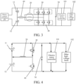
- a battery self-heating control system includes a battery pack 10, a winding 20, a first switch assembly 30, a second switch assembly 40, a capacitor 50, and a controller (not shown in the figure).
- the battery pack 10 includes a first battery group 11 and a second battery group 12 that are connected in series.
- a connection line is led out between the first battery group 11 and the second battery group 12.
- the connection line is connected to one end of the winding 20.
- the first switch assembly 30 and the second switch assembly 40 are connected in series.
- the first switch assembly 30 is electrically connected to a positive electrode of the first battery group 11 and a first end of the capacitor 50.
- the second switch assembly 40 is electrically connected to a negative electrode of the second battery group 12 and a second end of the capacitor 50.
- the first end and the second end of the capacitor 50 are used for connecting to a load 100.
- the other end of the winding 20 is connected between the first switch assembly 30 and the second switch assembly 40.
- the controller is electrically connected to the first switch assembly 30 and the second switch assembly 40.
- the controller is configured to control the first switch assembly 30 and the second switch assembly 40 to switch between an on state and an open state, and make the first battery group 11 and the second battery group 12 perform alternate charging and discharging through the winding 20, to heat the battery pack 50.
- At least one of the first battery group 11, the second battery group 12, and the capacitor 50 is configured to supply power to the load.
- connection line led out between the first battery group 11 and the second battery group 12 is connected to one end of the winding 20.
- the first switch assembly 30 and the second switch assembly 40 are connected in series.
- the first switch assembly 30 is electrically connected to the positive electrode of the first battery group 11 and the first end of the capacitor 50.
- the second switch assembly 40 is electrically connected to the negative electrode of the second battery group 12 and the second end of the capacitor 50.
- the first end and the second end of the capacitor 50 are used for connecting to the load 100. Therefore, the first switch assembly 30 and the second switch assembly 40 may be switched between the on state and the open state, so that the first battery group 11 and the second battery group 12 can charge or discharge each other.
- the first battery group 11 After the first battery group 11 charges the second battery group 12, the first battery group 11 may be charged through the second battery group 12, so that a current direction of the first battery group 11 changes periodically, and a current direction of the second battery group 12 changes periodically, which is equivalent to that an alternating current exists between the first battery group 11 and the second battery group 12.
- the controller is electrically connected to the first switch assembly 30 and the second switch assembly 40. Therefore, the controller may control the first switch assembly 30 and the second switch assembly 40 to switch between the on state and the open state, which is equivalent to that an alternating current exists between the first battery group 11 and the second battery group 12, and the first battery group 11 and the second battery group 12 perform alternate charging and discharging to heat the battery pack 10, i.e., perform self-heating of the battery pack 10.
- both the first battery group 11 and the second battery group 12 are electrically connected to the winding 20, the first battery group 11 and the second battery group 12 perform mutual charging and discharging through the winding 20, and the first battery group 11 and the second battery group 12 charge the capacitor 50, so that the first battery group 11 and the second battery group 12 can supply power to the load 100, and the capacitor 50 can also supply power to the load 100.
- the controller controls the first switch assembly 30 and the second switch assembly 40 to switch between the on state and the open state, so that it is equivalent to that an alternating current exists between the first battery group 11 and the second battery group 12.
- An effect of interlacing oscillations can be generated between the first battery group 11 and the second battery group 12 through the alternating current, so that the battery pack 10 can generate heat, to avoid heating the battery pack 10 in an external heating manner.
- heating is performed inside the battery pack 10, so that a temperature field distribution of the battery pack 10 can be uniform, thereby improving heating efficiency.
- the current direction of the first battery group 11 is a first direction.
- a direction of the first battery group 11 is a second direction.
- the first direction is opposite to the second direction.
- the first battery group 11 and the second battery group 12 perform alternate charging and discharging, so that the current direction of the first battery group 11 is alternately switched.
- the first battery group 11 has an alternating current, so that the first battery group 11 can perform self-heating.
- the self-heating of the second battery group 12 refer to a process of self-heating of the first battery group 11 for details, and details are not described herein again.
- the winding 20 may be an inductor.
- the electric transportation means includes an electric motor, and a winding 20 of the electric motor may be used as the winding 20 in the control system, i.e., the battery pack 10 is electrically connected to the winding 20 of the electric motor.
- the winding 20 may alternatively be another component specifically configured to store energy, or may alternatively be a component configured to carry and transfer energy through an alternating current.
- the controller when the control system is used in the electric transportation means, the controller may be a body control module (BCM) in the electric transportation means.
- BCM body control module
- the controller may alternatively be another controller having a control function in the electric transportation means. This is not limited in the embodiments of the present disclosure.
- the first switch assembly 30 and the second switch assembly 40 may be insulated gate bipolar transistors (IGBTs) or metal-oxide semiconductor field-effect transistors (MOSFETs).
- IGBTs insulated gate bipolar transistors
- MOSFETs metal-oxide semiconductor field-effect transistors
- the first switch assembly 30 and the second switch assembly 40 may alternatively be of other types.
- the first switch assembly 30 and the second switch assembly 40 may alternatively be other thyristors.
- bridge arms of an electric motor controller in the electric transportation means may also be used as the first switch assembly 30 and the second switch assembly 40, i.e., the battery pack 10 is electrically connected to the bridge arms of the electric motor controller.
- the load 100 when the control system is used in the electric transportation means, the load 100 may be the electric motor controller 101 and the other high-voltage loads 102. Certainly, the load 100 may alternatively be the other high-voltage loads 102 only, or may alternatively be only the electric motor controller 101.
- the first switch assembly 30 and the second switch assembly 40 have different conduction states at a same moment.
- the first switch assembly 30 is in the on state
- the second switch assembly 40 is in the open state
- the first switch assembly 30 is in the open state
- the second switch assembly 40 is in the on state.
- both the first battery group 11 and the second battery group 12 may be independent battery packs 10.
- the first battery group 11 and the second battery group 12 may alternatively be two parts of a same battery pack 10. In this case, a center line of the battery pack 10 is led out.
- the first battery group 11 may alternatively include a number of battery cores connected in series or in parallel
- the second battery group 12 may alternatively include a number of battery cores connected in series or in parallel.
- a quantity of battery cores in the first battery group 11 and a quantity of battery cores in the second battery group 12 may be equal, or certainly may be not equal. This is not limited in the embodiments of the present disclosure.
- the controller in a case that the control system is in a first state, within a first half cycle of each control cycle of the controller, the controller is configured to control the first switch assembly 30 and the second switch assembly 40 to switch between the on state and the open state, and the first battery group 11 to charge the winding 20 and charge the second battery group 12 through the winding 20.
- the capacitor 50 and/or the first battery group 11 are/is configured to supply power to the load 100.
- the controller is configured to control the first switch assembly 30 and the second switch assembly 40 to switch between the on state and the open state, and the second battery group 12 to charge the winding 20 and charge the first battery group 11 through the winding 20.
- the capacitor 50 and/or the second battery group 12 are/is configured to supply power to the load 100.
- the control cycle of the controller includes a number of cycles. Within each control cycle, within the first half cycle of each control cycle, the controller controls the first switch assembly 30 and the second switch assembly 40 to switch between the on state and the open state. When the first switch assembly 30 is turned on, the second switch assembly 40 is turned off, and when the first switch assembly 30 is turned off, the second switch assembly 40 is turned on. Therefore, voltages of the first battery group 11 and the second battery group 12 are different, and the first battery group 11 charges the winding 20 and charges the second battery group 12 through the winding 20.
- the controller controls the first switch assembly 30 and the second switch assembly 40 to switch between the on state and the open state.
- the first switch assembly 30 is turned on, the second switch assembly 40 is turned off, and when the first switch assembly 30 is turned off, the second switch assembly 40 is turned on. Therefore, the voltages of the first battery group 11 and the second battery group 12 are different, and the second battery group 12 charges the winding 20 and charges the first battery group 11 through the winding 20.
- the second battery group 12 charges the winding 20
- electric energy of the second battery group 12 is also transferred to the capacitor 50, so that the capacitor 50 and/or the second battery group 12 also charge/charges the load.
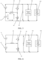
- the controller controls the first switch assembly 30 to be in a closed state and the second switch assembly 40 to be in the open state, the first battery group 11 to charge the winding 20, and the capacitor 50 to supply power to the load.
- the controller controls the first switch assembly 30 to be in the open state and the second switch assembly 40 to be in the closed state, the winding 20 to charge the second battery group 12, and the first battery group 11 and the capacitor 50 to supply power to the load.
- the voltage of the first battery group 11 is greater than the voltage of the second battery group 12, and the first battery group 11 charges the winding 20, so that the winding 20 can store electric energy, and the electric energy stored in the capacitor 50 is used to supply power to the load 100.
- the voltage of the first battery group 11 is greater than the voltage of the second battery group 12, and the first battery group 11 charges the winding 20, so that the winding 20 can store electric energy, and the electric energy stored in the capacitor 50 is used to supply power to the load 100.
- the controller controls the first switch assembly 30 to cycle states within the first time period and the second time period and the second switch assembly 40 to cycle states within the first time period and the second time period, it is equivalent to that the first switch assembly 30, the second switch assembly 40, the winding 20, and the capacitor 50 form a boost circuit, so that the first battery group 11 supplies power to the load 100 through the boost circuit, the first battery group 11 continuously discharges to the second battery group 12, and the second battery group 12 is continuously charged.
- the controller controls the first switch assembly to be in the open state, and controls the second switch assembly to be in the closed state, the second battery group to charge the winding, and the capacitor to supply power to the load.
- the controller controls the first switch assembly to be in the closed state and the second switch assembly to be in the open state, the winding to charge the first battery group, and the second battery group and the capacitor to supply power to the load.
- the controller controls the first switch assembly 30 to be in the open state, and the second switch assembly 40 to be in the closed state.
- the controller controls the first switch assembly 30 to be in the closed state, and the second switch assembly 40 to be in the open state.
- the controller controls the first switch assembly 30 to be in the closed state, and the second switch assembly 40 to be in the open state.
- FIG. 6 when the first switch assembly 30 is in the open state and the second switch assembly 40 is in the closed state within the third time period, in this case, after the first battery group 11 is continuously charged, the voltage of the second battery group 12 is greater than the voltage of the first battery group 11, and the second battery group 12 charges the winding 20, so that the winding 20 can store electric energy, and the electric energy stored in the capacitor 50 is used to supply power to the load 100.
- FIG. 6 when the first switch assembly 30 is in the open state and the second switch assembly 40 is in the closed state within the third time period, in this case, after the first battery group 11 is continuously charged, the voltage of the second battery group 12 is greater than the
- the controller controls the first switch assembly 30 to cycle states within the third time period and the fourth time period and the second switch assembly 40 to cycle states within the third time period and the fourth time period, it is equivalent to that the first switch assembly 30, the second switch assembly 40, the winding 20, and the capacitor 50 form a boost circuit, so that the second battery group 12 supplies power to the load 100 through the boost circuit, the second battery group 12 continuously discharges to the first battery group 11, and the first battery group 11 is continuously charged.
- each control cycle is cycled, i.e., states of the first switch assembly 30 and the second switch assembly 40 are cycled within the control cycles, so that the first battery group 11 and the second battery group 12 perform alternate charging and discharging.
- the first battery group 11 discharges to the second battery group 12, and the second battery group 12 is charged.
- the second battery group 12 discharges to the first battery group 11, and the first battery group 11 is charged.
- the first battery group 11 and the second battery group 12 perform alternate charging and discharging, it is equivalent to that an alternating current exists between the first battery group 11 and the second battery group 12, so that the battery pack 10 can perform self-heating.
- the control cycle of the controller is cycled, i.e., after the first time period, the second time period, the third time period, and the fourth time period
- the control of the first switch assembly 30 and the second switch assembly 40 within the first time period, the second time period, the third time period, and the fourth time period is repeated.
- the second battery group 12 charges the first battery group 11, so that the voltage of the first battery group 11 is greater than the voltage of the second battery group 12.
- the first battery group 11 charges the second battery group 12, and then the cycle is repeated.
- a first control cycle is adjacent to a second control cycle
- the second control cycle is a current control cycle
- the first control cycle is a control cycle before the second control cycle.
- the second battery group 12 charges the first battery group 11, so that the voltage of the first battery group 11 is greater than the voltage of the second battery group 12.
- a first time period of the second control cycle is entered, and the first battery group 11 charges the first battery group 11.
- each control cycle may have a short time.
- duration of the control cycle is 1 millisecond.
- the first time period, the second time period, the third time period, and the fourth time period form a complete control cycle.
- the first time period and the second time period form the first half cycle
- the third time period and the fourth time period form the second half cycle
- the first half cycle and the second half cycle form a complete control cycle.
- the first state when the control system is used in the electric transportation means, the first state may be a state in which the electric transportation means is in a driving self-heating state, i.e., the first state is the driving self-heating state. This is equivalent to self-heating of the battery pack 10 during driving, i.e., during traveling, of the electric transportation means.
- the control system if a battery level of the first battery group 11 is different from a battery level of the second battery group 12, the control system is in a second state. In a case that the control system is in the second state, the battery level of the first battery group 11 is greater than the battery level of the second battery group 12.
- the controller controls the first switch assembly 30 and the second switch assembly 40 to switch between the on state and the open state, and controls the first switch assembly 30 to be in the closed state and the second switch assembly 40 to be in the open state, the first battery group 11 to charge the winding 20, and the first battery group 11, the second battery group 12, and the capacitor 50 to supply power to the load 100.
- the controller controls the first switch assembly 30 to be in the open state and the second switch assembly 40 to be in the closed state, the winding 20 to charge the second battery group 12, and the first battery group 11 and the second battery group 12 to supply power to the capacitor 50 and the load 100.
- the battery level of the second battery group 12 is greater than the battery level of the first battery group 11.
- the controller controls the first switch assembly 30 to be in the open state, and controls the second switch assembly 40 to be in the closed state, the second battery group 12 to charge the winding 20, and the first battery group 11, the second battery group 12, and the capacitor 50 to supply power to the load 100.
- the controller controls the first switch assembly 30 to be in the closed state and the second switch assembly 40 to be in the open state, the winding 20 to charge the first battery group 11, and the first battery group 11 and the second battery group 12 to supply power to the capacitor and the load 100.
- the second state may be a balanced state, i.e., the battery levels of the first battery group 11 and the second battery group 12 are balanced.
- a balancing function may be activated, so that the electric transportation means is in the balanced state.
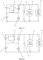
- the controller controls the first switch assembly 30 to be in the closed state, and the second switch assembly 40 to be in the open state.
- the first battery group 11 is connected in series to the first switch assembly 30, and charges the winding 20 through the first switch assembly 30.
- the first battery group 11 is connected in series to the second battery group 12, the first battery group 11 and the second battery group 12 supply power to the load 100, and the capacitor 50 also supplies power to the load 100.
- the controller controls the first switch assembly 30 to be in the open state, and the second switch assembly 40 to be in the closed state.
- the winding 20 and the second battery group 12 form a complete path through the second switch assembly 40, and the winding 20 charges the second battery group 12.
- the first battery group 11 is connected in series to the second battery group 12, and the first battery group 11 and the second battery group 12 supply power to the load 100, and charges the capacitor 50.
- first time period and the second time period may form a control cycle, and the first time period and the second time period are alternately cycled, so that the first battery group 11 continuously discharges to the second battery group 12, and finally, the battery levels of the first battery group 11 and the second battery group 12 are balanced, and the first battery group 11 and the second battery group 12 supply power to the load 100.
- the controller controls the first switch assembly 30 to be in the open state, and the second switch assembly 40 to be in the closed state.
- the second battery group 12 is connected in series to the second switch assembly 40, and charges the winding 20 through the second switch assembly 40.
- the second battery group 12 is connected in series to the first battery group 11, the second battery group 12 and the first battery group 11 supply power to the load 100, and the capacitor 50 also supplies power to the load 100.
- the controller controls the first switch assembly 30 to be in the closed state, and the second switch assembly 40 to be in the open state.
- the winding 20 and the first battery group 11 form a complete path through the first switch assembly 30, and the winding 20 charges the first battery group 11.
- the first battery group 11 is connected in series to the second battery group 12, and the first battery group 11 and the second battery group 12 supply power to the load 100, and charges the capacitor 50.
- the third time period and the fourth time period may form a control cycle, and the third time period and the fourth time period are alternately cycled, so that the second battery group 12 continuously discharges to the first battery group 11, and finally, the battery levels of the second battery group 12 and the first battery group 11 are balanced, and the first battery group 11 and the second battery group 12 supply power to the load 100.
- the controller alternately cyclically controls the first switch assembly 30 and the second switch assembly 40 in the first time period and the second time period, so that the first battery group 11 continuously discharges to the second battery group 12, and the battery levels of the first battery group 11 and the second battery group 12 are balanced. If the battery level of the second battery group 12 is greater than the battery level of the first battery group 11, the controller alternately cyclically controls the first switch assembly 30 and the second switch assembly 40 in the third time period and the fourth time period, so that the second battery group 12 continuously discharges to the first battery group 11, and the battery levels of the second battery group 12 and the first battery group 11 are balanced.
- the controller controls the first switch assembly 30 to be in the closed state, the second switch assembly 40 to be in the open state, and the first battery group 11 to charge the winding 20.
- the controller controls the first switch assembly 30 to be in the open state, the second switch assembly 40 to be in the closed state, and the winding 20 to charge the second battery group 12.
- the controller controls the first switch assembly 30 to be in the open state, and controls the second switch assembly 40 to be in the closed state, and the second battery group 12 to charge the winding 20.
- the controller controls the first switch assembly 30 to be in the closed state, the second switch assembly 40 to be in the open state, and the winding 20 to charge the first battery group 11.
- the third state may be a parking heating state, i.e., a state in which the electric transportation means stops driving and the battery pack 10 performs self-heating.
- a parking heating function is activated, and the control system is in the third state.
- the control cycle of the controller includes a number of cycles.
- the controller controls the first switch assembly 30 to be in the closed state, and the second switch assembly 40 to be in the open state.
- the controller controls the first switch assembly 30 to be in the open state, and the second switch assembly 40 to be in the closed state.
- the voltage of the first battery group 11 is greater than the voltage of the second battery group 12, and the first battery group 11 charges the winding 20, so that the winding 20 can store electric energy.
- FIG. 12 when the first switch assembly 30 is in the closed state and the second switch assembly 40 is in the open state within the first time period, in this case, the voltage of the first battery group 11 is greater than the voltage of the second battery group 12, and the first battery group 11 charges the winding 20, so that the winding 20 can store electric energy.
- the first switch assembly 30 within the second time period, the first switch assembly 30 is in the open state, and the second switch assembly 40 is in the closed state.
- the winding 20 and the second battery group 12 form a complete path through the second switch assembly 40, and the winding 20 charges the second battery group 12.
- the controller controls the first switch assembly 30 to cycle states within the first time period and the second time period and the second switch assembly 40 to cycle states within the first time period and the second time period, the first battery group 11 continuously discharges to the second battery group 12, and the second battery group 12 is continuously charged.
- the controller controls the first switch assembly 30 to be in the open state, and the second switch assembly 40 to be in the closed state.
- the controller controls the first switch assembly 30 to be in the closed state, and the second switch assembly 40 to be in the open state.
- the controller controls the first switch assembly 30 to be in the closed state, and the second switch assembly 40 to be in the open state.
- FIG. 14 when the first switch assembly 30 is in the open state and the second switch assembly 40 is in the closed state within the third time period, in this case, after the first battery group 11 is continuously charged, the voltage of the second battery group 12 is greater than the voltage of the first battery group 11, and the second battery group 12 charges the winding 20, so that the winding 20 can store electric energy, and the electric energy stored in the capacitor 50 is used to supply power to the load 100.
- FIG. 14 when the first switch assembly 30 is in the open state and the second switch assembly 40 is in the closed state within the third time period, in this case, after the first battery group 11 is continuously charged, the voltage of the second battery group 12 is greater than the
- the first switch assembly 30 is in the closed state, and the second switch assembly 40 is in the open state.
- the winding 20 and the first battery group 11 form a complete path through the first switch assembly 30, and the winding 20 charges the first battery group 11.
- the controller controls the first switch assembly 30 to cycle states within the third time period and the fourth time period and the second switch assembly 40 to cycle states within the third time period and the fourth time period, the second battery group 12 continuously discharges to the first battery group 11, and the first battery group 11 is continuously charged.
- each control cycle is cycled, i.e., states of the first switch assembly 30 and the second switch assembly 40 are cycled within the control cycles, so that the first battery group 11 and the second battery group 12 perform alternate charging and discharging.
- the first battery group 11 discharges to the second battery group 12, and the second battery group 12 is charged.
- the second battery group 12 discharges to the first battery group 11, and the first battery group 11 is charged.
- the first battery group 11 and the second battery group 12 perform alternate charging and discharging, it is equivalent to that an alternating current exists between the first battery group 11 and the second battery group 12, so that the battery pack 10 can perform self-heating.
- the control cycle of the controller is cycled, i.e., after the first time period, the second time period, the third time period, and the fourth time period
- the control of the first switch assembly 30 and the second switch assembly 40 within the first time period, the second time period, the third time period, and the fourth time period is repeated.
- the second battery group 12 charges the first battery group 11, so that the voltage of the first battery group 11 is greater than the voltage of the second battery group 12.
- the first battery group 11 charges the second battery group 12, and then the cycle is repeated.
- a first control cycle is adjacent to a second control cycle
- the second control cycle is a current control cycle
- the first control cycle is a control cycle before the second control cycle.
- the second battery group 12 charges the first battery group 11, so that the voltage of the first battery group 11 is greater than the voltage of the second battery group 12.
- a first time period of the second control cycle is entered, and the first battery group 11 charges the first battery group 11.
- the controller controls the first switch assembly 30 and the second switch assembly 40 to be alternately in the on state, so that the winding 20, the first switch assembly 30, the second switch assembly 40, and the capacitor 50 form a boost circuit, and the first battery group 11 supplies power to the load 100 through the boost circuit.
- the controller controls the first switch assembly 30 and the second switch assembly 40 to be alternately in the on state, and makes the winding 20, the first switch assembly 30, the second switch assembly 40, and the capacitor 50 form a boost circuit.
- the second battery group 12 supplies power to the load 100 through the boost circuit.
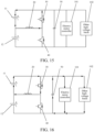
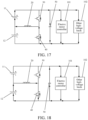
- the controller controls the first switch assembly 30 and the second switch assembly 40 to be alternately in the on state. As shown in FIG. 16 , within the first time period, the first switch assembly 30 is in the closed state and the second switch assembly 40 is in the on state, the first battery group 11 charges the winding 20 through the first switch assembly 30, and electric energy stored in the capacitor 50 is used to supply power to the load 100. As shown in FIG. 16
- the first switch assembly 30 is in the open state
- the second switch assembly 40 is in the on state
- the first battery group 11 is connected in series to the winding 20 to charge the capacitor 50 and supply power to the load 100. That is, the first switch assembly 30 is switched between the on state and the open state, and the second switch assembly 40 is switched between the on state and the open state.
- the second switch assembly 40 When the first switch assembly 30 is turned on, the second switch assembly 40 is turned off, and when the first switch assembly 30 is turned off, the second switch assembly 40 is turned on, so that the winding 20, the first switch assembly 30, the second switch assembly 40, and the capacitor 50 can form a boost circuit, the voltage of the first battery group 11 can be boosted to meet a voltage required by the load 100, i.e., the first battery group 11 supplies power to the load 100.
- the controller controls the first switch assembly 30 and the second switch assembly 40 to be alternately in the on state.
- the first switch assembly 30 is in the open state and the second switch assembly 40 is in the on state, the second battery group 12 charges the winding 20 through the second switch assembly 40, and electric energy stored in the capacitor 50 is used to supply power to the load 100.
- FIG. 18 shows that within the third time period, the first switch assembly 30 is in the open state and the second switch assembly 40 is in the on state, the second battery group 12 charges the winding 20 through the second switch assembly 40, and electric energy stored in the capacitor 50 is used to supply power to the load 100.
- the first switch assembly 30 is in the on state
- the second switch assembly 40 is in the open state
- the second battery group 12 is connected in series to the winding 20 to charge the capacitor 50 and supply power to the load 100. That is, the first switch assembly 30 is switched between the on state and the open state, and the second switch assembly 40 is switched between the on state and the open state.
- the second switch assembly 40 When the first switch assembly 30 is turned on, the second switch assembly 40 is turned off, and when the first switch assembly 30 is turned off, the second switch assembly 40 is turned on, so that the winding 20, the first switch assembly 30, the second switch assembly 40, and the capacitor 50 can form a boost circuit, the voltage of the second battery group 12 can be boosted to meet a voltage required by the load 100, i.e., the second battery group 12 supplies power to the load 100.
- a switch device 60 is arranged on the connection line.
- the switch device 60 is electrically connected to the controller.
- the controller is configured to control the switch device 60 to be in the on state or the open state.
- the switch device 60 When the switch device 60 is in the on state, the battery pack 10 supplies power to the load 100 and performs self-heating. In a case that the switch device 60 is in the open state, the battery pack 10 supplies power to the load 100 only.
- the switch device 60 When the switch device 60 is arranged on the connection line and the switch device 60 is electrically connected to the controller, in this case, when only the battery pack 10 needs to supply power to the load 100, as shown in FIG. 2 , the controller controls the switch device 60 to be in the open state, and the first battery group 11 and the second battery group 12 are connected in series to supply power to the load 100.
- the controller controls the switch device 60 to be in the on state, and controls the first switch assembly 30 and the second switch assembly 40 to be alternately switched between the on state and the open state, so that the battery pack 10 performs self-heating and can supply power to the load 100.
- the switch device 60 is arranged on the connection line, so that functional diversity of the control system can be achieved.
- the switch device 60 may be IGBTs or MOSFETs.
- a specific type of the switch device 60 is not limited in the embodiments of the present disclosure.
- connection line led out between the first battery group 11 and the second battery group 12 is connected to one end of the winding 20.
- the first switch assembly 30 and the second switch assembly 40 are connected in series.
- the first switch assembly 30 is electrically connected to the positive electrode of the first battery group 11 and the first end of the capacitor 50.
- the second switch assembly 40 is electrically connected to the negative electrode of the second battery group 12 and the second end of the capacitor 50.
- the first end and the second end of the capacitor 50 are used for connecting to the load 100. Therefore, the first switch assembly 30 and the second switch assembly 40 may be switched between the on state and the open state, so that the first battery group 11 and the second battery group 12 can charge or discharge each other.
- the first battery group 11 After the first battery group 11 charges the second battery group 12, the first battery group 11 may be charged through the second battery group 12, so that a current direction of the first battery group 11 changes periodically, and a current direction of the second battery group 12 changes periodically, which is equivalent to that an alternating current exists between the first battery group 11 and the second battery group 12.
- the controller is electrically connected to the first switch assembly 30 and the second switch assembly 40. Therefore, the controller may control the first switch assembly 30 and the second switch assembly 40 to switch between the on state and the open state, which is equivalent to that an alternating current exists between the first battery group 11 and the second battery group 12, and the first battery group 11 and the second battery group 12 perform alternate charging and discharging to heat the battery pack 10, i.e., perform self-heating of the battery pack 10.
- both the first battery group 11 and the second battery group 12 are electrically connected to the winding 20, the first battery group 11 and the second battery group 12 perform mutual charging and discharging through the winding 20, and the first battery group 11 and the second battery group 12 charge the capacitor 50, so that the first battery group 11 and the second battery group 12 can supply power to the load 100, and the capacitor 50 can also supply power to the load 100.
- the controller controls the first switch assembly 30 and the second switch assembly 40 to switch between the on state and the open state, so that it is equivalent to that an alternating current exists between the first battery group 11 and the second battery group 12.
- An effect of interlacing oscillations can be generated between the first battery group 11 and the second battery group 12 through the alternating current, so that the battery pack 10 can generate heat, to avoid heating the battery pack 10 in an external heating manner.
- heating is performed inside the battery pack 10, so that a temperature field distribution of the battery pack 10 can be uniform, thereby improving heating efficiency.
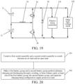
- FIG. 20 is a flowchart of a control method according to an embodiment of the present disclosure.
- the control method is applied to the battery pack self-heating control system in any embodiment of the foregoing embodiments. As shown in FIG. 20 , the method includes the following steps:
- connection line led out between the first battery group and the second battery group is connected to one end of the winding.
- the first switch assembly and the second switch assembly are connected in series.
- the first switch assembly is electrically connected to the positive electrode of the first battery group and the first end of the capacitor.
- the second switch assembly is electrically connected to the negative electrode of the second battery group and the second end of the capacitor.
- the first end and the second end of the capacitor are used for connecting to the load. Therefore, the first switch assembly and the second switch assembly may be switched between the on state and the open state, so that the first battery group and the second battery group can charge or discharge each other.
- the first battery group may be charged through the second battery group, so that a current direction of the first battery group changes periodically, and a current direction of the second battery group changes periodically, which is equivalent to that an alternating current exists between the first battery group and the second battery group.
- the controller is electrically connected to the first switch assembly and the second switch assembly. Therefore, the controller may control the first switch assembly and the second switch assembly to switch between the on state and the open state, which is equivalent to that an alternating current exists between the first battery group and the second battery group, and the first battery group and the second battery group perform alternate charging and discharging to heat the battery pack, i.e., perform self-heating of the battery pack.
- both the first battery group and the second battery group are electrically connected to the winding, the first battery group and the second battery group perform mutual charging and discharging through the winding, and the first battery group and the second battery group charge the capacitor, so that the first battery group and the second battery group can supply power to the load, and the capacitor can also supply power to the load.
- the controller controls the first switch assembly and the second switch assembly to switch between the on state and the open state, so that it is equivalent to that an alternating current exists between the first battery group and the second battery group.
- An effect of interlacing oscillations can be generated between the first battery group and the second battery group through the alternating current, so that the battery pack can generate heat, to avoid heating the battery pack 10 in an external heating manner.
- heating is performed inside the battery pack, so that a temperature field distribution of the battery pack can be uniform, thereby improving heating efficiency.
- the controlling the first switch assembly and the second switch assembly to switch between the on state and the open state, to provide an alternating current between the first battery group and the second battery group, and making the first battery group and the second battery group perform alternate charging and discharging includes:
- the first switch assembly and the second switch assembly controlling, within a first half cycle of each control cycle, the first switch assembly and the second switch assembly to switch between the on state and the open state, and the first battery group to charge the winding and charge the second battery group through the winding, the capacitor or the first battery group and the capacitor being configured to supply power to the load; and controlling, within a second half cycle of each control cycle, the first switch assembly and the second switch assembly to switch between the on state and the open state, and the second battery group to charge the winding and charge the first battery group through the winding, the capacitor or the second battery group and the capacitor being configured to supply power to the load.
- the controlling, within a first half cycle of each control cycle, the first switch assembly and the second switch assembly to switch between the on state and the open state, and the first battery group to charge the winding and charge the second battery group through the winding, the capacitor or the first battery group and the capacitor being configured to supply power to the load includes:
- the controlling, within a second half cycle of each control cycle, the first switch assembly and the second switch assembly to switch between the on state and the open state, and the second battery group to charge the winding and charge the first battery group through the winding, the capacitor or the second battery group and the capacitor being configured to supply power to the load includes:
- the controlling the first switch assembly and the second switch assembly to switch between the on state and the open state, to provide an alternating current between the first battery group and the second battery group, and making the first battery group and the second battery group perform alternate charging and discharging includes:
- the controlling the first switch assembly and the second switch assembly to switch between the on state and the open state, to provide an alternating current between the first battery group and the second battery group, and making the first battery group and the second battery group perform alternate charging and discharging further includes:
- the method further includes: in a case that the second battery group is damaged, controlling the first switch assembly and the second switch assembly to be alternately in the on state, and making the winding, the first switch assembly, the second switch assembly, and the capacitor form a boost circuit, the first battery group supplying power to the load through the boost circuit; and in a case that the first battery group is damaged, controlling the first switch assembly and the second switch assembly to be alternately in the on state, and making the winding, the first switch assembly, the second switch assembly, and the capacitor form a boost circuit, the second battery group supplying power to the load through the boost circuit.
- Embodiments of the present disclosure provide an electric transportation means.
- the electric transportation means includes the battery self-heating control system in any embodiment of the foregoing embodiments.
- the electric transportation means may further include a charging interface, and the charging interface is electrically connected to a battery pack to charge the battery pack.
- the charging interface is electrically connected to the battery pack 10, and therefore the battery pack 10 may be charged through the charging interface.
- the first switch assembly 30 and the second switch assembly 40 may be further controlled through a controller, to make the battery pack 10 perform self-heating.
Landscapes
- Engineering & Computer Science (AREA)
- Power Engineering (AREA)
- Mechanical Engineering (AREA)
- Transportation (AREA)
- Life Sciences & Earth Sciences (AREA)
- Sustainable Energy (AREA)
- Sustainable Development (AREA)
- Chemical & Material Sciences (AREA)
- General Chemical & Material Sciences (AREA)
- Electrochemistry (AREA)
- Chemical Kinetics & Catalysis (AREA)
- Manufacturing & Machinery (AREA)
- Automation & Control Theory (AREA)
- Charge And Discharge Circuits For Batteries Or The Like (AREA)
- Electric Propulsion And Braking For Vehicles (AREA)
Abstract
Description
- The present disclosure claims priority to
Chinese Patent Application No. 202211068408.3 published on August 31, 2022 - The present disclosure relates to the technical field of battery self-heating control systems, and specifically, to a battery self-heating control system and control method, and an electric transportation means.
- With the development of science and technology, electric transportation means gradually become main transportation means for people to travel daily. For example, electric vehicles have gradually become the mainstream. Generally, a battery pack is arranged in an electric transportation means, and the battery pack supplies power to a load in the electric transportation means. However, the battery pack is affected by temperature. At a low temperature, the electrical performance of the battery pack is degraded, which seriously affects the discharging performance of the battery pack, resulting in problems such as shortened driving mileage and limited output power during driving.
- In the related art, the battery pack is heated in an external heating manner, i.e., a battery heater is arranged to heat the battery. When it is detected that the temperature of the battery pack is excessively low, a switch inside the battery heater is turned on, so that a resistor of the battery heater is energized to generate heat, and the generated heat flows to the battery pack through an air channel or a water channel to heat the battery pack.
- Because a pipe of the air channel or the water channel is long, heat loss is large, and as a result the battery pack has a slow heating speed and a long heating time, affecting a heating effect.
- Embodiments of the present disclosure provide a battery self-heating control system, to resolve the problems in the related art that a battery pack has a slow heating speed and a long heating time due to a large heat loss caused by a long pipe of an air channel or a water channel, and in addition, a heating effect is affected due to a nonuniform temperature field distribution of the battery when the battery pack is heated through the air channel or the water channel.
- In order to resolve the above technical problems, the present disclosure is implemented as follows:
Embodiments of the present disclosure provide a battery self-heating control system. The control system includes a battery pack, a winding, a first switch assembly, a second switch assembly, a capacitor, and a controller. - The battery pack includes a first battery group and a second battery group that are connected in series. A connection line is led out between the first battery group and the second battery group. The connection line is connected to one end of the winding.
- The first switch assembly and the second switch assembly are connected in series. The first switch assembly is electrically connected to a positive electrode of the first battery group and a first end of the capacitor. The second switch assembly is electrically connected to a negative electrode of the second battery group and a second end of the capacitor. The first end and the second end of the capacitor are used for connecting to a load. The other end of the winding is connected between the first switch assembly and the second switch assembly.
- The controller is electrically connected to the first switch assembly and the second switch assembly. The controller is configured to control the first switch assembly and the second switch assembly to switch between an on state and an open state, and make the first battery group and the second battery group perform alternate charging and discharging through the winding, to heat the battery pack. At least one of the first battery group, the second battery group, and the capacitor is configured to supply power to the load.
- Optionally, in a case that the control system is in a first state, within a first half cycle of each control cycle of the controller, the controller is configured to control the first switch assembly and the second switch assembly to switch between the on state and the open state, and the first battery group to charge the winding and charge the second battery group through the winding. The capacitor and/or the first battery group are/is configured to supply power to the load.
- Within a second half cycle of each control cycle of the controller, the controller is configured to control the first switch assembly and the second switch assembly to switch between the on state and the open state, and the second battery group to charge the winding and charge the first battery group through the winding. The capacitor and/or the second battery group are/is configured to supply power to the load.
- Optionally, within a first time period of the first half cycle, the controller controls the first switch assembly to be in a closed state and the second switch assembly to be in the open state, the first battery group to charge the winding, and the capacitor to supply power to the load.
- Within a second time period of the first half cycle, the controller controls the first switch assembly to be in the open state and the second switch assembly to be in the closed state, the winding to charge the second battery group, and the first battery group and the capacitor to supply power to the load.
- Optionally, within a third time period of the second half cycle, the controller controls the first switch assembly to be in the open state, and controls the second switch assembly to be in the closed state, the second battery group to charge the winding, and the capacitor to supply power to the load.
- Within a fourth time period of the second half cycle, the controller controls the first switch assembly to be in the closed state and the second switch assembly to be in the open state, the winding to charge the first battery group, and the second battery group and the capacitor to supply power to the load.
- Optionally, in a case that the control system is in a second state, a battery level of the first battery group is greater than a battery level of the second battery group. Within the first time period of each control cycle, the controller controls the first switch assembly and the second switch assembly to switch between the on state and the open state, and controls the first switch assembly to be in the closed state and the second switch assembly to be in the open state, the first battery group to charge the winding, and the first battery group, the second battery group, and the capacitor to supply power to the load.
- Within the second time period of each control cycle, the controller controls the first switch assembly to be in the open state and the second switch assembly to be in the closed state, the winding to charge the second battery group, and the first battery group and the second battery group to supply power to the capacitor and the load.
- Optionally, in a case that the control system is in the second state, the battery level of the first battery group is greater than the battery level of the second battery group. Within the third time period of each control cycle, the controller controls the first switch assembly to be in the open state, and controls the second switch assembly to be in the closed state, the second battery group to charge the winding, and the first battery group, the second battery group, and the capacitor to supply power to the load.
- Within the fourth time period of each control cycle, the controller controls the first switch assembly to be in the closed state and the second switch assembly to be in the open state, the winding to charge the first battery group, and the first battery group and the second battery group to supply power to the capacitor and the load.
- Optionally, in a case that the second battery group is damaged, the controller controls the first switch assembly and the second switch assembly to be alternately in the on state, and makes the winding, the first switch assembly, the second switch assembly, and the capacitor form a boost circuit. The first battery group supplies power to the load through the boost circuit.
- In a case that the first battery group is damaged, the controller controls the first switch assembly and the second switch assembly to be alternately in the on state, and makes the winding, the first switch assembly, the second switch assembly, and the capacitor form a boost circuit. The second battery group supplies power to the load through the boost circuit.
- Optionally, a switch device is arranged on the connection line. The switch device is electrically connected to the controller. The controller is configured to control the switch device to be in the on state or the open state.
- In a case that the switch device is in the on state, the battery pack supplies power to the load, and performs self-heating.
- In a case that the switch device is in the open state, the battery pack supplies power to the load only.
- According to a second aspect, embodiments of the present disclosure provide a control method, including:
- controlling a first switch assembly and a second switch assembly to switch between an on state and an open state; and
- making a first battery group and a second battery group perform alternate charging and discharging through a winding, to heat a battery pack, at least one of the first battery group, the second battery group, and capacitor charging being configured to supply power to a load.
- Optionally, in a case that the control system is in a first state, the controlling the first switch assembly and the second switch assembly to switch between the on state and the open state, to provide an alternating current between the first battery group and the second battery group, and making the first battery group and the second battery group perform alternate charging and discharging includes:
- controlling, within a first half cycle of each control cycle, the first switch assembly and the second switch assembly to switch between the on state and the open state, and the first battery group to charge the winding and charge the second battery group through the winding, the capacitor or the first battery group and the capacitor being configured to supply power to the load; and
- controlling, within a second half cycle of each control cycle, the first switch assembly and the second switch assembly to switch between the on state and the open state, and the second battery group to charge the winding and charge the first battery group through the winding, the capacitor or the second battery group and the capacitor being configured to supply power to the load.
- Optionally, the controlling, within a first half cycle of each control cycle, the first switch assembly and the second switch assembly to switch between the on state and the open state, and the first battery group to charge the winding and charge the second battery group through the winding, the capacitor or the first battery group and the capacitor being configured to supply power to the load includes:
- within a first time period of the first half cycle, controlling the first switch assembly to be in a closed state and the second switch assembly to be in the open state, the first battery group to charge the winding, and the capacitor to supply power to the load; and
- within a second time period of the first half cycle, controlling the first switch assembly to be in the open state and the second switch assembly to be in the closed state, the winding to charge the second battery group, and the first battery group and the capacitor to supply power to the load.
- Optionally, the controlling, within a second half cycle of each control cycle, the first switch assembly and the second switch assembly to switch between the on state and the open state, and the second battery group to charge the winding and charge the first battery group through the winding, the capacitor or the second battery group and the capacitor being configured to supply power to the load includes:
- within a third time period of the second half cycle, controlling the first switch assembly to be in the open state, and controlling the second switch assembly to be in the closed state, the second battery group to charge the winding, and the capacitor to supply power to the load;
- within a fourth time period of the second half cycle, controlling the first switch assembly to be in the closed state and the second switch assembly to be in the open state, the winding to charge the first battery group, and the second battery group and the capacitor to supply power to the load.
- Optionally, in a case that the control system is in a second state, the controlling the first switch assembly and the second switch assembly to switch between the on state and the open state, to provide an alternating current between the first battery group and the second battery group, and making the first battery group and the second battery group perform alternate charging and discharging includes:
- when a battery level of the first battery group is greater than a battery level of the second battery group, within the first time period of each control cycle, controlling the first switch assembly and the second switch assembly to switch between the on state and the open state, and controlling the first switch assembly to be in the closed state and the second switch assembly to be in the open state, the first battery group to charge the winding, and the first battery group, the second battery group, and the capacitor to supply power to the load; and
- within the second time period of each control cycle, controlling the first switch assembly to be in the open state and the second switch assembly to be in the closed state, the winding to charge the second battery group, and the first battery group and the second battery group to supply power to the capacitor and the load.
- Optionally, in a case that the control system is in a second state, the controlling the first switch assembly and the second switch assembly to switch between the on state and the open state, to provide an alternating current between the first battery group and the second battery group, and making the first battery group and the second battery group perform alternate charging and discharging,further includes:
- in a case that the control system is in the second state, when the battery level of the first battery group is greater than the battery level of the second battery group, within the third time period of each control cycle, controlling the first switch assembly to be in the open state, and controlling the second switch assembly to be in the closed state, the second battery group to charge the winding, and the first battery group, the second battery group, and the capacitor to supply power to the load; and
- within the fourth time period of each control cycle, controlling the first switch assembly to be in the closed state and the second switch assembly to be in the open state, the winding to charge the first battery group, and the first battery group and the second battery group to supply power to the capacitor and the load.
- Optionally, the method further includes: in a case that the second battery group is damaged, controlling the first switch assembly and the second switch assembly to be alternately in the on state, and making the winding, the first switch assembly, the second switch assembly, and the capacitor form a boost circuit, the first battery group supplying power to the load through the boost circuit; and
in a case that the first battery group is damaged, controlling the first switch assembly and the second switch assembly to be alternately in the on state, and making the winding, the first switch assembly, the second switch assembly, and the capacitor form a boost circuit, the second battery group supplying power to the load through the boost circuit. - According to a third aspect, embodiments of the present disclosure provide an electric transportation means, including the foregoing battery self-heating control system according to any of the first aspect.
- In the embodiments of the present disclosure, the connection line led out between the first battery group and the second battery group is connected to one end of the winding. The first switch assembly and the second switch assembly are connected in series. The first switch assembly is electrically connected to the positive electrode of the first battery group and the first end of the capacitor. The second switch assembly is electrically connected to the negative electrode of the second battery group and the second end of the capacitor. The first end and the second end of the capacitor are used for connecting to the load. Therefore, the first switch assembly and the second switch assembly may be switched between the on state and the open state, so that the first battery group and the second battery group can charge or discharge each other. After the first battery group charges the second battery group, the first battery group may be charged through the second battery group, so that a current direction of the first battery group changes periodically, and a current direction of the second battery group changes periodically, which is equivalent to that an alternating current exists between the first battery group and the second battery group. The controller is electrically connected to the first switch assembly and the second switch assembly. Therefore, the controller may control the first switch assembly and the second switch assembly to switch between the on state and the open state, which is equivalent to that an alternating current exists between the first battery group and the second battery group, and the first battery group and the second battery group perform alternate charging and discharging to heat the battery pack, i.e., perform self-heating of the battery pack. In addition, when the first battery group and the second battery group perform alternate charging and discharging, both the first battery group and the second battery group are electrically connected to the winding, the first battery group and the second battery group perform mutual charging and discharging through the winding, and the first battery group and the second battery group charge the capacitor, so that the first battery group and the second battery group can supply power to the load, and the capacitor can also supply power to the load.
- In other words, in the embodiments of the present disclosure, the controller controls the first switch assembly and the second switch assembly to switch between the on state and the open state, so that it is equivalent to that an alternating current exists between the first battery group and the second battery group. An effect of interlacing oscillations can be generated between the first battery group and the second battery group through the alternating current, so that the battery pack can generate heat, to avoid heating the
battery pack 10 in an external heating manner. In addition, heating is performed inside the battery pack, so that a temperature field distribution of the battery pack can be uniform, thereby improving heating efficiency. -
-
FIG. 1 is a schematic diagram 1 of a battery self-heating control system according to an embodiment of the present disclosure; -
FIG. 2 is a schematic diagram 2 of a battery self-heating control system according to an embodiment of the present disclosure; -
FIG. 3 is a schematic diagram 3 of a battery self-heating control system according to an embodiment of the present disclosure; -
FIG. 4 is a schematic diagram 1 of a current flow direction in a first state according to an embodiment of the present disclosure; -
FIG. 5 is a schematic diagram 2 of a current flow direction in a first state according to an embodiment of the present disclosure; -
FIG. 6 is a schematic diagram 3 of a current flow direction in a first state according to an embodiment of the present disclosure; -
FIG. 7 is a schematic diagram 4 of a current flow direction in a first state according to an embodiment of the present disclosure; -
FIG. 8 is a schematic diagram 1 of a current flow direction in a second state according to an embodiment of the present disclosure; -
FIG. 9 is a schematic diagram 2 of a current flow direction in a second state according to an embodiment of the present disclosure; -
FIG. 10 is a schematic diagram 3 of a current flow direction in a second state according to an embodiment of the present disclosure; -
FIG. 11 is a schematic diagram 4 of a current flow direction in a second state according to an embodiment of the present disclosure; -
FIG. 12 is a schematic diagram 1 of a current flow direction in a third state according to an embodiment of the present disclosure; -
FIG. 13 is a schematic diagram 2 of a current flow direction in a third state according to an embodiment of the present disclosure; -
FIG. 14 is a schematic diagram 3 of a current flow direction in a third state according to an embodiment of the present disclosure; -
FIG. 15 is a schematic diagram 4 of a current flow direction in a third state according to an embodiment of the present disclosure; -
FIG. 16 is a schematic diagram 1 of a current flow direction when a second battery group is damaged according to an embodiment of the present disclosure; -
FIG. 17 is a schematic diagram 2 of a current flow direction when a second battery group is damaged according to an embodiment of the present disclosure; -
FIG. 18 is a schematic diagram 1 of a current flow direction when a first battery group is damaged according to an embodiment of the present disclosure; -
FIG. 19 is a schematic diagram 2 of a current flow direction when a first battery group is damaged according to an embodiment of the present disclosure; and -
FIG. 20 is a flowchart of a control method according to an embodiment of the present disclosure. - In the drawings:
10: battery pack; 20: winding; 30: first switch assembly; 40: second switch assembly; 50: capacitor; 60: switch device; 11: first battery group; 12: second battery group; 100: load; 101: electric motor controller; and 102: other high-voltage loads. - The following clearly and completely describes the technical solutions in the embodiments of the present disclosure with reference to the accompanying drawings in the embodiments of the present disclosure. Apparently, the described embodiments are some of the embodiments of the present disclosure rather than all of the embodiments. All other embodiments obtained by a person of ordinary skill in the art based on the embodiments of the present disclosure without creative efforts shall fall within the protection scope of the present disclosure.
- It should be understood that "one embodiment" or "an embodiment" mentioned throughout the specification means that a particular feature, structure, or characteristic related to the embodiment is included in at least one embodiment of the present disclosure. Therefore, "in one embodiment" or "in an embodiment" appearing everywhere throughout the specification may not necessarily refer to the same embodiment. In addition, the specific features, structures, or characteristics may be combined in one or more embodiments in any suitable manner.
- As shown in
FIG. 1 , a battery self-heating control system includes abattery pack 10, a winding 20, afirst switch assembly 30, asecond switch assembly 40, acapacitor 50, and a controller (not shown in the figure). - The
battery pack 10 includes afirst battery group 11 and asecond battery group 12 that are connected in series. A connection line is led out between thefirst battery group 11 and thesecond battery group 12. The connection line is connected to one end of the winding 20. Thefirst switch assembly 30 and thesecond switch assembly 40 are connected in series. Thefirst switch assembly 30 is electrically connected to a positive electrode of thefirst battery group 11 and a first end of thecapacitor 50. Thesecond switch assembly 40 is electrically connected to a negative electrode of thesecond battery group 12 and a second end of thecapacitor 50. The first end and the second end of thecapacitor 50 are used for connecting to aload 100. The other end of the winding 20 is connected between thefirst switch assembly 30 and thesecond switch assembly 40. The controller is electrically connected to thefirst switch assembly 30 and thesecond switch assembly 40. The controller is configured to control thefirst switch assembly 30 and thesecond switch assembly 40 to switch between an on state and an open state, and make thefirst battery group 11 and thesecond battery group 12 perform alternate charging and discharging through the winding 20, to heat thebattery pack 50. At least one of thefirst battery group 11, thesecond battery group 12, and thecapacitor 50 is configured to supply power to the load. - In the embodiments of the present disclosure, the connection line led out between the
first battery group 11 and thesecond battery group 12 is connected to one end of the winding 20. Thefirst switch assembly 30 and thesecond switch assembly 40 are connected in series. Thefirst switch assembly 30 is electrically connected to the positive electrode of thefirst battery group 11 and the first end of thecapacitor 50. Thesecond switch assembly 40 is electrically connected to the negative electrode of thesecond battery group 12 and the second end of thecapacitor 50. The first end and the second end of thecapacitor 50 are used for connecting to theload 100. Therefore, thefirst switch assembly 30 and thesecond switch assembly 40 may be switched between the on state and the open state, so that thefirst battery group 11 and thesecond battery group 12 can charge or discharge each other. After thefirst battery group 11 charges thesecond battery group 12, thefirst battery group 11 may be charged through thesecond battery group 12, so that a current direction of thefirst battery group 11 changes periodically, and a current direction of thesecond battery group 12 changes periodically, which is equivalent to that an alternating current exists between thefirst battery group 11 and thesecond battery group 12. The controller is electrically connected to thefirst switch assembly 30 and thesecond switch assembly 40. Therefore, the controller may control thefirst switch assembly 30 and thesecond switch assembly 40 to switch between the on state and the open state, which is equivalent to that an alternating current exists between thefirst battery group 11 and thesecond battery group 12, and thefirst battery group 11 and thesecond battery group 12 perform alternate charging and discharging to heat thebattery pack 10, i.e., perform self-heating of thebattery pack 10. In addition, when thefirst battery group 11 and thesecond battery group 12 perform alternate charging and discharging, both thefirst battery group 11 and thesecond battery group 12 are electrically connected to the winding 20, thefirst battery group 11 and thesecond battery group 12 perform mutual charging and discharging through the winding 20, and thefirst battery group 11 and thesecond battery group 12 charge thecapacitor 50, so that thefirst battery group 11 and thesecond battery group 12 can supply power to theload 100, and thecapacitor 50 can also supply power to theload 100. - In other words, in the embodiments of the present disclosure, the controller controls the
first switch assembly 30 and thesecond switch assembly 40 to switch between the on state and the open state, so that it is equivalent to that an alternating current exists between thefirst battery group 11 and thesecond battery group 12. An effect of interlacing oscillations can be generated between thefirst battery group 11 and thesecond battery group 12 through the alternating current, so that thebattery pack 10 can generate heat, to avoid heating thebattery pack 10 in an external heating manner. In addition, heating is performed inside thebattery pack 10, so that a temperature field distribution of thebattery pack 10 can be uniform, thereby improving heating efficiency. - It should be noted that, when the
first battery group 11 charges thesecond battery group 12, the current direction of thefirst battery group 11 is a first direction. When thesecond battery group 12 charges thefirst battery group 11, a direction of thefirst battery group 11 is a second direction. The first direction is opposite to the second direction. Thefirst battery group 11 and thesecond battery group 12 perform alternate charging and discharging, so that the current direction of thefirst battery group 11 is alternately switched. This is equivalent to that thefirst battery group 11 has an alternating current, so that thefirst battery group 11 can perform self-heating. For the self-heating of thesecond battery group 12, refer to a process of self-heating of thefirst battery group 11 for details, and details are not described herein again. - It should further be noted that, in the embodiments of the present disclosure, the winding 20 may be an inductor. When the control system is used in an electric transportation means, the electric transportation means includes an electric motor, and a winding 20 of the electric motor may be used as the winding 20 in the control system, i.e., the
battery pack 10 is electrically connected to the winding 20 of the electric motor. In addition, the winding 20 may alternatively be another component specifically configured to store energy, or may alternatively be a component configured to carry and transfer energy through an alternating current. - In addition, in the embodiments of the present disclosure, when the control system is used in the electric transportation means, the controller may be a body control module (BCM) in the electric transportation means. Certainly, the controller may alternatively be another controller having a control function in the electric transportation means. This is not limited in the embodiments of the present disclosure.
- In addition, in the embodiments of the present disclosure, the
first switch assembly 30 and thesecond switch assembly 40 may be insulated gate bipolar transistors (IGBTs) or metal-oxide semiconductor field-effect transistors (MOSFETs). Certainly, thefirst switch assembly 30 and thesecond switch assembly 40 may alternatively be of other types. For example, thefirst switch assembly 30 and thesecond switch assembly 40 may alternatively be other thyristors. In addition, in the embodiments of the present disclosure, when the control system is used in the electric transportation means, as shown inFIG. 3 , bridge arms of an electric motor controller in the electric transportation means may also be used as thefirst switch assembly 30 and thesecond switch assembly 40, i.e., thebattery pack 10 is electrically connected to the bridge arms of the electric motor controller. - In addition, in the embodiments of the present disclosure, the
capacitor 50 may be an additionalindependent capacitor 50. When the control system is used in the electric transportation means, thecapacitor 50 may alternatively be integrated with anelectric motor controller 101 in the electric transportation means, or thecapacitor 50 may alternatively be integrated with other high-voltage loads 102 in the electric transportation means. Certainly, thecapacitor 50 may alternatively not be integrated with theelectric motor controller 101 or the other high-voltage loads 102. This is not limited in the embodiments of the present disclosure. - In addition, in the embodiments of the present disclosure, when the control system is used in the electric transportation means, the
load 100 may be theelectric motor controller 101 and the other high-voltage loads 102. Certainly, theload 100 may alternatively be the other high-voltage loads 102 only, or may alternatively be only theelectric motor controller 101. - In addition, in the embodiments of the present disclosure, the
first switch assembly 30 and thesecond switch assembly 40 have different conduction states at a same moment. When thefirst switch assembly 30 is in the on state, thesecond switch assembly 40 is in the open state, and when thefirst switch assembly 30 is in the open state, thesecond switch assembly 40 is in the on state. - In addition, in the embodiments of the present disclosure, both the
first battery group 11 and thesecond battery group 12 may be independent battery packs 10. Certainly, thefirst battery group 11 and thesecond battery group 12 may alternatively be two parts of asame battery pack 10. In this case, a center line of thebattery pack 10 is led out. In addition, thefirst battery group 11 may alternatively include a number of battery cores connected in series or in parallel, and thesecond battery group 12 may alternatively include a number of battery cores connected in series or in parallel. A quantity of battery cores in thefirst battery group 11 and a quantity of battery cores in thesecond battery group 12 may be equal, or certainly may be not equal. This is not limited in the embodiments of the present disclosure. - In addition, in some embodiments, as shown in
FIG. 4 to FIG. 7 , in a case that the control system is in a first state, within a first half cycle of each control cycle of the controller, the controller is configured to control thefirst switch assembly 30 and thesecond switch assembly 40 to switch between the on state and the open state, and thefirst battery group 11 to charge the winding 20 and charge thesecond battery group 12 through the winding 20. Thecapacitor 50 and/or thefirst battery group 11 are/is configured to supply power to theload 100. Within a second half cycle of each control cycle of the controller, the controller is configured to control thefirst switch assembly 30 and thesecond switch assembly 40 to switch between the on state and the open state, and thesecond battery group 12 to charge the winding 20 and charge thefirst battery group 11 through the winding 20. Thecapacitor 50 and/or thesecond battery group 12 are/is configured to supply power to theload 100. - When the control system is in the first state, the control cycle of the controller includes a number of cycles. Within each control cycle, within the first half cycle of each control cycle, the controller controls the
first switch assembly 30 and thesecond switch assembly 40 to switch between the on state and the open state. When thefirst switch assembly 30 is turned on, thesecond switch assembly 40 is turned off, and when thefirst switch assembly 30 is turned off, thesecond switch assembly 40 is turned on. Therefore, voltages of thefirst battery group 11 and thesecond battery group 12 are different, and thefirst battery group 11 charges the winding 20 and charges thesecond battery group 12 through the winding 20. In addition, when thefirst battery group 11 charges the winding 20, electric energy of thefirst battery group 11 is also transferred to thecapacitor 50, so that thecapacitor 50 and/or thefirst battery group 11 also charge/charges the load. Within the second half cycle of each control cycle, the controller controls thefirst switch assembly 30 and thesecond switch assembly 40 to switch between the on state and the open state. When thefirst switch assembly 30 is turned on, thesecond switch assembly 40 is turned off, and when thefirst switch assembly 30 is turned off, thesecond switch assembly 40 is turned on. Therefore, the voltages of thefirst battery group 11 and thesecond battery group 12 are different, and thesecond battery group 12 charges the winding 20 and charges thefirst battery group 11 through the winding 20. In addition, when thesecond battery group 12 charges the winding 20, electric energy of thesecond battery group 12 is also transferred to thecapacitor 50, so that thecapacitor 50 and/or thesecond battery group 12 also charge/charges the load. - Specifically, the first half cycle may include a first time period and a second time period, the second half cycle may include a third time period and a fourth time period, the first time period and the second time period form a complete first half cycle, and the third time period and the fourth time period form a complete second half cycle.
- Within the first time period of the first half cycle, the controller controls the
first switch assembly 30 to be in a closed state and thesecond switch assembly 40 to be in the open state, thefirst battery group 11 to charge the winding 20, and thecapacitor 50 to supply power to the load. Within the second time period of the first half cycle, the controller controls thefirst switch assembly 30 to be in the open state and thesecond switch assembly 40 to be in the closed state, the winding 20 to charge thesecond battery group 12, and thefirst battery group 11 and thecapacitor 50 to supply power to the load. - As shown in
FIG. 4 , when thefirst switch assembly 30 is controlled to be in the closed state and thesecond switch assembly 40 is controlled to be in the open state within the first time period, in this case, the voltage of thefirst battery group 11 is greater than the voltage of thesecond battery group 12, and thefirst battery group 11 charges the winding 20, so that the winding 20 can store electric energy, and the electric energy stored in thecapacitor 50 is used to supply power to theload 100. As shown inFIG. 5 , when thefirst switch assembly 30 is in the open state and thesecond switch assembly 40 is in the closed state within the second time period, in this case, it is equivalent to that thefirst battery group 11 is connected in series to the winding 20, so that thefirst battery group 11 and the winding 20 jointly supply power to theload 100, and the winding 20 charges thesecond battery group 12. When the controller controls thefirst switch assembly 30 to cycle states within the first time period and the second time period and thesecond switch assembly 40 to cycle states within the first time period and the second time period, it is equivalent to that thefirst switch assembly 30, thesecond switch assembly 40, the winding 20, and thecapacitor 50 form a boost circuit, so that thefirst battery group 11 supplies power to theload 100 through the boost circuit, thefirst battery group 11 continuously discharges to thesecond battery group 12, and thesecond battery group 12 is continuously charged. - Within the third time period of the second half cycle, the controller controls the first switch assembly to be in the open state, and controls the second switch assembly to be in the closed state, the second battery group to charge the winding, and the capacitor to supply power to the load. Within the fourth time period of the second half cycle, the controller controls the first switch assembly to be in the closed state and the second switch assembly to be in the open state, the winding to charge the first battery group, and the second battery group and the capacitor to supply power to the load.
- Within the third time period, the controller controls the
first switch assembly 30 to be in the open state, and thesecond switch assembly 40 to be in the closed state. Within the fourth time period, the controller controls thefirst switch assembly 30 to be in the closed state, and thesecond switch assembly 40 to be in the open state. As shown inFIG. 6 , when thefirst switch assembly 30 is in the open state and thesecond switch assembly 40 is in the closed state within the third time period, in this case, after thefirst battery group 11 is continuously charged, the voltage of thesecond battery group 12 is greater than the voltage of thefirst battery group 11, and thesecond battery group 12 charges the winding 20, so that the winding 20 can store electric energy, and the electric energy stored in thecapacitor 50 is used to supply power to theload 100. As shown inFIG. 7 , when thefirst switch assembly 30 is in the closed state and thesecond switch assembly 40 is in the open state within the fourth time period, in this case, it is equivalent to that thesecond battery group 12 is connected in series to the winding 20, so that thesecond battery group 12 and the winding 20 jointly supply power to theload 100, and the winding 20 charges thefirst battery group 11. When the controller controls thefirst switch assembly 30 to cycle states within the third time period and the fourth time period and thesecond switch assembly 40 to cycle states within the third time period and the fourth time period, it is equivalent to that thefirst switch assembly 30, thesecond switch assembly 40, the winding 20, and thecapacitor 50 form a boost circuit, so that thesecond battery group 12 supplies power to theload 100 through the boost circuit, thesecond battery group 12 continuously discharges to thefirst battery group 11, and thefirst battery group 11 is continuously charged. - When the controller controls the
first switch assembly 30 and thesecond switch assembly 40 in a number of control cycles, it is equivalent to that each control cycle is cycled, i.e., states of thefirst switch assembly 30 and thesecond switch assembly 40 are cycled within the control cycles, so that thefirst battery group 11 and thesecond battery group 12 perform alternate charging and discharging. To be specific, within the first time period and the second time period of the first half cycle of each control cycle, thefirst battery group 11 discharges to thesecond battery group 12, and thesecond battery group 12 is charged. Within the third time period and the fourth time period of the second half cycle, thesecond battery group 12 discharges to thefirst battery group 11, and thefirst battery group 11 is charged. In addition, when thefirst battery group 11 and thesecond battery group 12 perform alternate charging and discharging, it is equivalent to that an alternating current exists between thefirst battery group 11 and thesecond battery group 12, so that thebattery pack 10 can perform self-heating. - In addition, when the control cycle of the controller is cycled, i.e., after the first time period, the second time period, the third time period, and the fourth time period, the control of the
first switch assembly 30 and thesecond switch assembly 40 within the first time period, the second time period, the third time period, and the fourth time period is repeated. Within one control cycle, in a fourth time period of a previous control cycle before the control cycle, thesecond battery group 12 charges thefirst battery group 11, so that the voltage of thefirst battery group 11 is greater than the voltage of thesecond battery group 12. After the cycle, within a first time period of a current control cycle, thefirst battery group 11 charges thesecond battery group 12, and then the cycle is repeated. - For example, a first control cycle is adjacent to a second control cycle, the second control cycle is a current control cycle, and the first control cycle is a control cycle before the second control cycle. Within a fourth time period of the first control cycle, the
second battery group 12 charges thefirst battery group 11, so that the voltage of thefirst battery group 11 is greater than the voltage of thesecond battery group 12. Next, a first time period of the second control cycle is entered, and thefirst battery group 11 charges thefirst battery group 11. - It should be noted that each control cycle may have a short time. For example, duration of the control cycle is 1 millisecond. In addition, the first time period, the second time period, the third time period, and the fourth time period form a complete control cycle. To be specific, the first time period and the second time period form the first half cycle, the third time period and the fourth time period form the second half cycle, and the first half cycle and the second half cycle form a complete control cycle.
- In addition, in the embodiments of the present disclosure, when the control system is used in the electric transportation means, the first state may be a state in which the electric transportation means is in a driving self-heating state, i.e., the first state is the driving self-heating state. This is equivalent to self-heating of the
battery pack 10 during driving, i.e., during traveling, of the electric transportation means. - In addition, in some embodiments, as shown in
FIG. 8 to FIG. 11 , if a battery level of thefirst battery group 11 is different from a battery level of thesecond battery group 12, the control system is in a second state. In a case that the control system is in the second state, the battery level of thefirst battery group 11 is greater than the battery level of thesecond battery group 12. Within the first time period of each control cycle, the controller controls thefirst switch assembly 30 and thesecond switch assembly 40 to switch between the on state and the open state, and controls thefirst switch assembly 30 to be in the closed state and thesecond switch assembly 40 to be in the open state, thefirst battery group 11 to charge the winding 20, and thefirst battery group 11, thesecond battery group 12, and thecapacitor 50 to supply power to theload 100. Within the second time period of each control cycle, the controller controls thefirst switch assembly 30 to be in the open state and thesecond switch assembly 40 to be in the closed state, the winding 20 to charge thesecond battery group 12, and thefirst battery group 11 and thesecond battery group 12 to supply power to thecapacitor 50 and theload 100. In addition, in a case that the control system is in the second state, the battery level of thesecond battery group 12 is greater than the battery level of thefirst battery group 11. Within the third time period of each control cycle, the controller controls thefirst switch assembly 30 to be in the open state, and controls thesecond switch assembly 40 to be in the closed state, thesecond battery group 12 to charge the winding 20, and thefirst battery group 11, thesecond battery group 12, and thecapacitor 50 to supply power to theload 100. Within the fourth time period, the controller controls thefirst switch assembly 30 to be in the closed state and thesecond switch assembly 40 to be in the open state, the winding 20 to charge thefirst battery group 11, and thefirst battery group 11 and thesecond battery group 12 to supply power to the capacitor and theload 100. - When the control system is used in the electric transportation means, the second state may be a balanced state, i.e., the battery levels of the
first battery group 11 and thesecond battery group 12 are balanced. For example, during driving, if the battery levels of thefirst battery group 11 and thesecond battery group 12 are different, a balancing function may be activated, so that the electric transportation means is in the balanced state. - In addition, if the battery level of the
first battery group 11 is greater than the battery level of thesecond battery group 12, as shown inFIG. 8 , within the first time period, the controller controls thefirst switch assembly 30 to be in the closed state, and thesecond switch assembly 40 to be in the open state. In this case, thefirst battery group 11 is connected in series to thefirst switch assembly 30, and charges the winding 20 through thefirst switch assembly 30. In addition, thefirst battery group 11 is connected in series to thesecond battery group 12, thefirst battery group 11 and thesecond battery group 12 supply power to theload 100, and thecapacitor 50 also supplies power to theload 100. As shown inFIG. 9 , within the second time period, the controller controls thefirst switch assembly 30 to be in the open state, and thesecond switch assembly 40 to be in the closed state. In this case, the winding 20 and thesecond battery group 12 form a complete path through thesecond switch assembly 40, and the winding 20 charges thesecond battery group 12. In addition, thefirst battery group 11 is connected in series to thesecond battery group 12, and thefirst battery group 11 and thesecond battery group 12 supply power to theload 100, and charges thecapacitor 50. - It should be noted that the first time period and the second time period may form a control cycle, and the first time period and the second time period are alternately cycled, so that the
first battery group 11 continuously discharges to thesecond battery group 12, and finally, the battery levels of thefirst battery group 11 and thesecond battery group 12 are balanced, and thefirst battery group 11 and thesecond battery group 12 supply power to theload 100. - In addition, if the battery level of the
second battery group 12 is greater than the battery level of thefirst battery group 11, as shown inFIG. 10 , within the third time period, the controller controls thefirst switch assembly 30 to be in the open state, and thesecond switch assembly 40 to be in the closed state. In this case, thesecond battery group 12 is connected in series to thesecond switch assembly 40, and charges the winding 20 through thesecond switch assembly 40. In addition, thesecond battery group 12 is connected in series to thefirst battery group 11, thesecond battery group 12 and thefirst battery group 11 supply power to theload 100, and thecapacitor 50 also supplies power to theload 100. As shown inFIG. 11 , within the fourth time period, the controller controls thefirst switch assembly 30 to be in the closed state, and thesecond switch assembly 40 to be in the open state. In this case, the winding 20 and thefirst battery group 11 form a complete path through thefirst switch assembly 30, and the winding 20 charges thefirst battery group 11. In addition, thefirst battery group 11 is connected in series to thesecond battery group 12, and thefirst battery group 11 and thesecond battery group 12 supply power to theload 100, and charges thecapacitor 50. - It should be noted that the third time period and the fourth time period may form a control cycle, and the third time period and the fourth time period are alternately cycled, so that the
second battery group 12 continuously discharges to thefirst battery group 11, and finally, the battery levels of thesecond battery group 12 and thefirst battery group 11 are balanced, and thefirst battery group 11 and thesecond battery group 12 supply power to theload 100. - In the embodiments of the present disclosure, if the battery level of the
first battery group 11 is greater than the battery level of thesecond battery group 12, the controller alternately cyclically controls thefirst switch assembly 30 and thesecond switch assembly 40 in the first time period and the second time period, so that thefirst battery group 11 continuously discharges to thesecond battery group 12, and the battery levels of thefirst battery group 11 and thesecond battery group 12 are balanced. If the battery level of thesecond battery group 12 is greater than the battery level of thefirst battery group 11, the controller alternately cyclically controls thefirst switch assembly 30 and thesecond switch assembly 40 in the third time period and the fourth time period, so that thesecond battery group 12 continuously discharges to thefirst battery group 11, and the battery levels of thesecond battery group 12 and thefirst battery group 11 are balanced. - In addition, in some embodiments, as shown in
FIG. 12 to FIG. 15 , in a case that the control system is in a third state, within each control cycle of the controller, within the first time period, the controller controls thefirst switch assembly 30 to be in the closed state, thesecond switch assembly 40 to be in the open state, and thefirst battery group 11 to charge the winding 20. Within the second time period, the controller controls thefirst switch assembly 30 to be in the open state, thesecond switch assembly 40 to be in the closed state, and the winding 20 to charge thesecond battery group 12. Within the third time period, the controller controls thefirst switch assembly 30 to be in the open state, and controls thesecond switch assembly 40 to be in the closed state, and thesecond battery group 12 to charge the winding 20. Within the fourth time period, the controller controls thefirst switch assembly 30 to be in the closed state, thesecond switch assembly 40 to be in the open state, and the winding 20 to charge thefirst battery group 11. - When the control system is used in the electric transportation means, the third state may be a parking heating state, i.e., a state in which the electric transportation means stops driving and the
battery pack 10 performs self-heating. For example, when the electric transportation means stops at a roadside and thebattery pack 10 needs to perform self-heating, a parking heating function is activated, and the control system is in the third state. - In addition, when the control system is in the first state, the control cycle of the controller includes a number of cycles. Within each control cycle, within the first time period, the controller controls the
first switch assembly 30 to be in the closed state, and thesecond switch assembly 40 to be in the open state. Within the second time period, the controller controls thefirst switch assembly 30 to be in the open state, and thesecond switch assembly 40 to be in the closed state. As shown inFIG. 12 , when thefirst switch assembly 30 is in the closed state and thesecond switch assembly 40 is in the open state within the first time period, in this case, the voltage of thefirst battery group 11 is greater than the voltage of thesecond battery group 12, and thefirst battery group 11 charges the winding 20, so that the winding 20 can store electric energy. As shown inFIG. 13 , within the second time period, thefirst switch assembly 30 is in the open state, and thesecond switch assembly 40 is in the closed state. In this case, the winding 20 and thesecond battery group 12 form a complete path through thesecond switch assembly 40, and the winding 20 charges thesecond battery group 12. When the controller controls thefirst switch assembly 30 to cycle states within the first time period and the second time period and thesecond switch assembly 40 to cycle states within the first time period and the second time period, thefirst battery group 11 continuously discharges to thesecond battery group 12, and thesecond battery group 12 is continuously charged. - Within the third time period, the controller controls the
first switch assembly 30 to be in the open state, and thesecond switch assembly 40 to be in the closed state. Within the fourth time period, the controller controls thefirst switch assembly 30 to be in the closed state, and thesecond switch assembly 40 to be in the open state. As shown inFIG. 14 , when thefirst switch assembly 30 is in the open state and thesecond switch assembly 40 is in the closed state within the third time period, in this case, after thefirst battery group 11 is continuously charged, the voltage of thesecond battery group 12 is greater than the voltage of thefirst battery group 11, and thesecond battery group 12 charges the winding 20, so that the winding 20 can store electric energy, and the electric energy stored in thecapacitor 50 is used to supply power to theload 100. As shown inFIG. 15 , within the fourth time period, thefirst switch assembly 30 is in the closed state, and thesecond switch assembly 40 is in the open state. In this case, the winding 20 and thefirst battery group 11 form a complete path through thefirst switch assembly 30, and the winding 20 charges thefirst battery group 11. When the controller controls thefirst switch assembly 30 to cycle states within the third time period and the fourth time period and thesecond switch assembly 40 to cycle states within the third time period and the fourth time period, thesecond battery group 12 continuously discharges to thefirst battery group 11, and thefirst battery group 11 is continuously charged. - When the controller controls the
first switch assembly 30 and thesecond switch assembly 40 in a number of control cycles, it is equivalent to that each control cycle is cycled, i.e., states of thefirst switch assembly 30 and thesecond switch assembly 40 are cycled within the control cycles, so that thefirst battery group 11 and thesecond battery group 12 perform alternate charging and discharging. To be specific, within the first time period and the second time period of each control cycle, thefirst battery group 11 discharges to thesecond battery group 12, and thesecond battery group 12 is charged. Within the third time period and the fourth time period, thesecond battery group 12 discharges to thefirst battery group 11, and thefirst battery group 11 is charged. In addition, when thefirst battery group 11 and thesecond battery group 12 perform alternate charging and discharging, it is equivalent to that an alternating current exists between thefirst battery group 11 and thesecond battery group 12, so that thebattery pack 10 can perform self-heating. - In addition, when the control cycle of the controller is cycled, i.e., after the first time period, the second time period, the third time period, and the fourth time period, the control of the
first switch assembly 30 and thesecond switch assembly 40 within the first time period, the second time period, the third time period, and the fourth time period is repeated. Within one control cycle, in a fourth time period of a previous control cycle before the control cycle, thesecond battery group 12 charges thefirst battery group 11, so that the voltage of thefirst battery group 11 is greater than the voltage of thesecond battery group 12. After the cycle, within a first time period of a current control cycle, thefirst battery group 11 charges thesecond battery group 12, and then the cycle is repeated. - For example, a first control cycle is adjacent to a second control cycle, the second control cycle is a current control cycle, and the first control cycle is a control cycle before the second control cycle. Within a fourth time period of the first control cycle, the
second battery group 12 charges thefirst battery group 11, so that the voltage of thefirst battery group 11 is greater than the voltage of thesecond battery group 12. Next, a first time period of the second control cycle is entered, and thefirst battery group 11 charges thefirst battery group 11. - In addition, in some embodiments, as shown in
FIG. 16 to FIG. 19 , in a case that thesecond battery group 12 is damaged, the controller controls thefirst switch assembly 30 and thesecond switch assembly 40 to be alternately in the on state, so that the winding 20, thefirst switch assembly 30, thesecond switch assembly 40, and thecapacitor 50 form a boost circuit, and thefirst battery group 11 supplies power to theload 100 through the boost circuit. In a case that thefirst battery group 11 is damaged, the controller controls thefirst switch assembly 30 and thesecond switch assembly 40 to be alternately in the on state, and makes the winding 20, thefirst switch assembly 30, thesecond switch assembly 40, and thecapacitor 50 form a boost circuit. Thesecond battery group 12 supplies power to theload 100 through the boost circuit. - When the
second battery group 12 is damaged, in this case, thesecond battery group 12 cannot supply power to theload 100, and thefirst battery group 11 supplies power to theload 100 only. The controller controls thefirst switch assembly 30 and thesecond switch assembly 40 to be alternately in the on state. As shown inFIG. 16 , within the first time period, thefirst switch assembly 30 is in the closed state and thesecond switch assembly 40 is in the on state, thefirst battery group 11 charges the winding 20 through thefirst switch assembly 30, and electric energy stored in thecapacitor 50 is used to supply power to theload 100. As shown inFIG. 17 , within the second time period, thefirst switch assembly 30 is in the open state, thesecond switch assembly 40 is in the on state, thefirst battery group 11 is connected in series to the winding 20 to charge thecapacitor 50 and supply power to theload 100. That is, thefirst switch assembly 30 is switched between the on state and the open state, and thesecond switch assembly 40 is switched between the on state and the open state. When thefirst switch assembly 30 is turned on, thesecond switch assembly 40 is turned off, and when thefirst switch assembly 30 is turned off, thesecond switch assembly 40 is turned on, so that the winding 20, thefirst switch assembly 30, thesecond switch assembly 40, and thecapacitor 50 can form a boost circuit, the voltage of thefirst battery group 11 can be boosted to meet a voltage required by theload 100, i.e., thefirst battery group 11 supplies power to theload 100. - Similarly, when the
first battery group 11 is damaged, in this case, thefirst battery group 11 cannot supply power to theload 100, and only thesecond battery group 12 supplies power to theload 100. The controller controls thefirst switch assembly 30 and thesecond switch assembly 40 to be alternately in the on state. As shown inFIG. 18 , within the third time period, thefirst switch assembly 30 is in the open state and thesecond switch assembly 40 is in the on state, thesecond battery group 12 charges the winding 20 through thesecond switch assembly 40, and electric energy stored in thecapacitor 50 is used to supply power to theload 100. As shown inFIG. 19 , within the fourth time period, thefirst switch assembly 30 is in the on state, thesecond switch assembly 40 is in the open state, thesecond battery group 12 is connected in series to the winding 20 to charge thecapacitor 50 and supply power to theload 100. That is, thefirst switch assembly 30 is switched between the on state and the open state, and thesecond switch assembly 40 is switched between the on state and the open state. When thefirst switch assembly 30 is turned on, thesecond switch assembly 40 is turned off, and when thefirst switch assembly 30 is turned off, thesecond switch assembly 40 is turned on, so that the winding 20, thefirst switch assembly 30, thesecond switch assembly 40, and thecapacitor 50 can form a boost circuit, the voltage of thesecond battery group 12 can be boosted to meet a voltage required by theload 100, i.e., thesecond battery group 12 supplies power to theload 100. - In addition, in some embodiments, as shown in
FIG. 2 orFIG. 3 , aswitch device 60 is arranged on the connection line. Theswitch device 60 is electrically connected to the controller. The controller is configured to control theswitch device 60 to be in the on state or the open state. When theswitch device 60 is in the on state, thebattery pack 10 supplies power to theload 100 and performs self-heating. In a case that theswitch device 60 is in the open state, thebattery pack 10 supplies power to theload 100 only. - When the
switch device 60 is arranged on the connection line and theswitch device 60 is electrically connected to the controller, in this case, when only thebattery pack 10 needs to supply power to theload 100, as shown inFIG. 2 , the controller controls theswitch device 60 to be in the open state, and thefirst battery group 11 and thesecond battery group 12 are connected in series to supply power to theload 100. When thebattery pack 10 needs to perform self-heating and supply power to theload 100, the controller controls theswitch device 60 to be in the on state, and controls thefirst switch assembly 30 and thesecond switch assembly 40 to be alternately switched between the on state and the open state, so that thebattery pack 10 performs self-heating and can supply power to theload 100. In other words, theswitch device 60 is arranged on the connection line, so that functional diversity of the control system can be achieved. - It should be noted that the
switch device 60 may be IGBTs or MOSFETs. A specific type of theswitch device 60 is not limited in the embodiments of the present disclosure. - In the embodiments of the present disclosure, the connection line led out between the
first battery group 11 and thesecond battery group 12 is connected to one end of the winding 20. Thefirst switch assembly 30 and thesecond switch assembly 40 are connected in series. Thefirst switch assembly 30 is electrically connected to the positive electrode of thefirst battery group 11 and the first end of thecapacitor 50. Thesecond switch assembly 40 is electrically connected to the negative electrode of thesecond battery group 12 and the second end of thecapacitor 50. The first end and the second end of thecapacitor 50 are used for connecting to theload 100. Therefore, thefirst switch assembly 30 and thesecond switch assembly 40 may be switched between the on state and the open state, so that thefirst battery group 11 and thesecond battery group 12 can charge or discharge each other. After thefirst battery group 11 charges thesecond battery group 12, thefirst battery group 11 may be charged through thesecond battery group 12, so that a current direction of thefirst battery group 11 changes periodically, and a current direction of thesecond battery group 12 changes periodically, which is equivalent to that an alternating current exists between thefirst battery group 11 and thesecond battery group 12. The controller is electrically connected to thefirst switch assembly 30 and thesecond switch assembly 40. Therefore, the controller may control thefirst switch assembly 30 and thesecond switch assembly 40 to switch between the on state and the open state, which is equivalent to that an alternating current exists between thefirst battery group 11 and thesecond battery group 12, and thefirst battery group 11 and thesecond battery group 12 perform alternate charging and discharging to heat thebattery pack 10, i.e., perform self-heating of thebattery pack 10. In addition, when thefirst battery group 11 and thesecond battery group 12 perform alternate charging and discharging, both thefirst battery group 11 and thesecond battery group 12 are electrically connected to the winding 20, thefirst battery group 11 and thesecond battery group 12 perform mutual charging and discharging through the winding 20, and thefirst battery group 11 and thesecond battery group 12 charge thecapacitor 50, so that thefirst battery group 11 and thesecond battery group 12 can supply power to theload 100, and thecapacitor 50 can also supply power to theload 100. - In other words, in the embodiments of the present disclosure, the controller controls the
first switch assembly 30 and thesecond switch assembly 40 to switch between the on state and the open state, so that it is equivalent to that an alternating current exists between thefirst battery group 11 and thesecond battery group 12. An effect of interlacing oscillations can be generated between thefirst battery group 11 and thesecond battery group 12 through the alternating current, so that thebattery pack 10 can generate heat, to avoid heating thebattery pack 10 in an external heating manner. In addition, heating is performed inside thebattery pack 10, so that a temperature field distribution of thebattery pack 10 can be uniform, thereby improving heating efficiency. -
FIG. 20 is a flowchart of a control method according to an embodiment of the present disclosure. The control method is applied to the battery pack self-heating control system in any embodiment of the foregoing embodiments. As shown inFIG. 20 , the method includes the following steps: - Step 201: Control a first switch assembly and a second switch assembly to switch between an on state and an open state.
- Step 202: Make a first battery group and a second battery group perform alternate charging and discharging through a winding, to heat a battery pack, at least one of the first battery group, the second battery group, and capacitor charging being configured to supply power to a load.
- In the embodiments of the present disclosure, the connection line led out between the first battery group and the second battery group is connected to one end of the winding. The first switch assembly and the second switch assembly are connected in series. The first switch assembly is electrically connected to the positive electrode of the first battery group and the first end of the capacitor. The second switch assembly is electrically connected to the negative electrode of the second battery group and the second end of the capacitor. The first end and the second end of the capacitor are used for connecting to the load. Therefore, the first switch assembly and the second switch assembly may be switched between the on state and the open state, so that the first battery group and the second battery group can charge or discharge each other. After the first battery group charges the second battery group, the first battery group may be charged through the second battery group, so that a current direction of the first battery group changes periodically, and a current direction of the second battery group changes periodically, which is equivalent to that an alternating current exists between the first battery group and the second battery group. The controller is electrically connected to the first switch assembly and the second switch assembly. Therefore, the controller may control the first switch assembly and the second switch assembly to switch between the on state and the open state, which is equivalent to that an alternating current exists between the first battery group and the second battery group, and the first battery group and the second battery group perform alternate charging and discharging to heat the battery pack, i.e., perform self-heating of the battery pack. In addition, when the first battery group and the second battery group perform alternate charging and discharging, both the first battery group and the second battery group are electrically connected to the winding, the first battery group and the second battery group perform mutual charging and discharging through the winding, and the first battery group and the second battery group charge the capacitor, so that the first battery group and the second battery group can supply power to the load, and the capacitor can also supply power to the load.
- In other words, in the embodiments of the present disclosure, the controller controls the first switch assembly and the second switch assembly to switch between the on state and the open state, so that it is equivalent to that an alternating current exists between the first battery group and the second battery group. An effect of interlacing oscillations can be generated between the first battery group and the second battery group through the alternating current, so that the battery pack can generate heat, to avoid heating the
battery pack 10 in an external heating manner. In addition, heating is performed inside the battery pack, so that a temperature field distribution of the battery pack can be uniform, thereby improving heating efficiency. - In addition, in some implementations, in a case that the control system is in a first state, the controlling the first switch assembly and the second switch assembly to switch between the on state and the open state, to provide an alternating current between the first battery group and the second battery group, and making the first battery group and the second battery group perform alternate charging and discharging includes:
- controlling, within a first half cycle of each control cycle, the first switch assembly and the second switch assembly to switch between the on state and the open state, and the first battery group to charge the winding and charge the second battery group through the winding, the capacitor or the first battery group and the capacitor being configured to supply power to the load; and
controlling, within a second half cycle of each control cycle, the first switch assembly and the second switch assembly to switch between the on state and the open state, and the second battery group to charge the winding and charge the first battery group through the winding, the capacitor or the second battery group and the capacitor being configured to supply power to the load. - In addition, in some implementations, the controlling, within a first half cycle of each control cycle, the first switch assembly and the second switch assembly to switch between the on state and the open state, and the first battery group to charge the winding and charge the second battery group through the winding, the capacitor or the first battery group and the capacitor being configured to supply power to the load includes:
- within a first time period of the first half cycle, controlling the first switch assembly to be in a closed state and the second switch assembly to be in the open state, the first battery group to charge the winding, and the capacitor to supply power to the load; and
- within a second time period of the first half cycle, controlling the first switch assembly to be in the open state and the second switch assembly to be in the closed state, the winding to charge the second battery group, and the first battery group and the capacitor to supply power to the load.
- In addition, in some implementations, the controlling, within a second half cycle of each control cycle, the first switch assembly and the second switch assembly to switch between the on state and the open state, and the second battery group to charge the winding and charge the first battery group through the winding, the capacitor or the second battery group and the capacitor being configured to supply power to the load includes:
- within a third time period of the second half cycle, controlling the first switch assembly to be in the open state, and controlling the second switch assembly to be in the closed state, the second battery group to charge the winding, and the capacitor to supply power to the load;
- within a fourth time period of the second half cycle, controlling the first switch assembly to be in the closed state and the second switch assembly to be in the open state, the winding to charge the first battery group, and the second battery group and the capacitor to supply power to the load.
- In addition, in some implementations, in a case that the control system is in a second state, the controlling the first switch assembly and the second switch assembly to switch between the on state and the open state, to provide an alternating current between the first battery group and the second battery group, and making the first battery group and the second battery group perform alternate charging and discharging includes:
- when a battery level of the first battery group is greater than a battery level of the second battery group, within the first time period of each control cycle, controlling the first switch assembly and the second switch assembly to switch between the on state and the open state, and controlling the first switch assembly to be in the closed state and the second switch assembly to be in the open state, the first battery group to charge the winding, and the first battery group, the second battery group, and the capacitor to supply power to the load; and
- within the second time period of each control cycle, controlling the first switch assembly to be in the open state and the second switch assembly to be in the closed state, the winding to charge the second battery group, and the first battery group and the second battery group to supply power to the capacitor and the load.
- In addition, in some implementations, in a case that the control system is in a second state, the controlling the first switch assembly and the second switch assembly to switch between the on state and the open state, to provide an alternating current between the first battery group and the second battery group, and making the first battery group and the second battery group perform alternate charging and discharging further includes:
- in a case that the control system is in the second state, when the battery level of the first battery group is greater than the battery level of the second battery group, within the third time period of each control cycle, controlling the first switch assembly to be in the open state, and controlling the second switch assembly to be in the closed state, the second battery group to charge the winding, and the first battery group, the second battery group, and the capacitor to supply power to the load; and
- within the fourth time period of each control cycle, controlling the first switch assembly to be in the closed state and the second switch assembly to be in the open state, the winding to charge the first battery group, and the first battery group and the second battery group to supply power to the capacitor and the load.
- In addition, in some implementations, the method further includes: in a case that the second battery group is damaged, controlling the first switch assembly and the second switch assembly to be alternately in the on state, and making the winding, the first switch assembly, the second switch assembly, and the capacitor form a boost circuit, the first battery group supplying power to the load through the boost circuit; and
in a case that the first battery group is damaged, controlling the first switch assembly and the second switch assembly to be alternately in the on state, and making the winding, the first switch assembly, the second switch assembly, and the capacitor form a boost circuit, the second battery group supplying power to the load through the boost circuit. - Embodiments of the present disclosure provide an electric transportation means. The electric transportation means includes the battery self-heating control system in any embodiment of the foregoing embodiments.
- In addition, in the embodiments of the present disclosure, the electric transportation means may further include a charging interface, and the charging interface is electrically connected to a battery pack to charge the battery pack.
- The charging interface is electrically connected to the
battery pack 10, and therefore thebattery pack 10 may be charged through the charging interface. In addition, in a process of charging thebattery pack 10, thefirst switch assembly 30 and thesecond switch assembly 40 may be further controlled through a controller, to make thebattery pack 10 perform self-heating. - It should be noted that the embodiments in this specification are all described in a progressive manner. Description of each of the embodiments focuses on differences from other embodiments, and reference may be made to each other for the same or similar parts among respective embodiments.
- Although optional embodiments of the embodiments of the present disclosure have been described, once knowing the basic creative concept, a person skilled in the art can make additional changes and modifications to these embodiments. Therefore, the following claims are intended to be construed as to cover the optional embodiments and all changes and modifications falling within the scope of the embodiments of the present disclosure.
- Finally, it should further be noted that the relational terms herein such as first and second are used only to differentiate an entity from another entity, and do not require or imply any actual relationship or sequence between these entities. Moreover, the term "include," "comprise," or any variation thereof is intended to cover a non-exclusive inclusion. Therefore, an object or a terminal apparatus that includes a series of elements not only includes such elements, but also includes other elements not specified expressly, or includes inherent elements of the object or terminal apparatus. If no more limitations are made, an element limited by "include a/an..." does not exclude other same elements existing in the article or the terminal apparatus which includes the element.
- The technical solutions provided in the present disclosure are described in detail above. The principles and implementations of the present disclosure are described in this specification by using specific examples. In addition, a person of ordinary skill in the art may make modifications to the specific implementations and application scopes according to the principles and implementations of the present disclosure. In summary, the content of this specification should not be construed as limiting the present disclosure.
Claims (10)
- A battery self-heating control system, the control system comprising: a battery pack, a winding, a first switch assembly, a second switch assembly, a capacitor, and a controller;the battery pack comprising a first battery group and a second battery group that are connected in series, a connection line being led out between the first battery group and the second battery group, and the connection line being connected to one end of the winding;the first switch assembly and the second switch assembly being connected in series, the first switch assembly being electrically connected to a positive electrode of the first battery group and a first end of the capacitor, the second switch assembly being electrically connected to a negative electrode of the second battery group and a second end of the capacitor, the first end and the second end of the capacitor being used for connecting to a load, and the other end of the winding being connected between the first switch assembly and the second switch assembly; andthe controller being electrically connected to the first switch assembly and the second switch assembly, the controller being configured to control the first switch assembly and the second switch assembly to switch between an on state and an open state, and make the first battery group and the second battery group perform alternate charging and discharging through the winding, to heat the battery pack, and at least one of the first battery group, the second battery group, and the capacitor being configured to supply power to the load.
- The battery self-heating control system according to claim 1, wherein in a case that the control system is in a first state, within a first half cycle of each control cycle of the controller, the controller is configured to control the first switch assembly and the second switch assembly to switch between the on state and the open state, and the first battery group to charge the winding and charge the second battery group through the winding, and the capacitor and/or the first battery group are/is configured to supply power to the load; and
within a second half cycle of each control cycle of the controller, the controller is configured to control the first switch assembly and the second switch assembly to switch between the on state and the open state, and the second battery group to charge the winding and charge the first battery group through the winding, and the capacitor and/or the second battery group are/is configured to supply power to the load. - The battery self-heating control system according to claim 2, wherein within a first time period of the first half cycle, the controller controls the first switch assembly to be in a closed state and the second switch assembly to be in the open state, the first battery group to charge the winding, and the capacitor to supply power to the load; and
within a second time period of the first half cycle, the controller controls the first switch assembly to be in the open state and the second switch assembly to be in the closed state, the winding to charge the second battery group, and the first battery group and the capacitor to supply power to the load. - The battery self-heating control system according to claim 2 or 3, wherein within a third time period of the second half cycle, the controller controls the first switch assembly to be in the open state, and controls the second switch assembly to be in the closed state, the second battery group to charge the winding, and the capacitor to supply power to the load; and
within a fourth time period of the second half cycle, the controller controls the first switch assembly to be in the closed state and the second switch assembly to be in the open state, the winding to charge the first battery group, and the second battery group and the capacitor to supply power to the load. - The battery self-heating control system according to any of claims 1 to 4, wherein in a case that the control system is in a second state, a battery level of the first battery group is greater than a battery level of the second battery group, and within the first time period of each control cycle, the controller controls the first switch assembly and the second switch assembly to switch between the on state and the open state, and controls the first switch assembly to be in the closed state and the second switch assembly to be in the open state, the first battery group to charge the winding, and the first battery group, the second battery group, and the capacitor to supply power to the load; and
within the second time period of each control cycle, the controller controls the first switch assembly to be in the open state and the second switch assembly to be in the closed state, the winding to charge the second battery group, and the first battery group and the second battery group to supply power to the capacitor and the load. - The battery self-heating control system according to any of claims 1 to 5, wherein in a case that the control system is in the second state, the battery level of the first battery group is greater than the battery level of the second battery group, and within the third time period of each control cycle, the controller controls the first switch assembly to be in the open state, and controls the second switch assembly to be in the closed state, the second battery group to charge the winding, and the first battery group, the second battery group, and the capacitor to supply power to the load; and
within the fourth time period of each control cycle, the controller controls the first switch assembly to be in the closed state and the second switch assembly to be in the open state, the winding to charge the first battery group, and the first battery group and the second battery group to supply power to the capacitor and the load. - The battery self-heating control system according to any of claims 1 to 6, wherein in a case that the second battery group is damaged, the controller controls the first switch assembly and the second switch assembly to be alternately in the on state, and makes the winding, the first switch assembly, the second switch assembly, and the capacitor form a boost circuit, and the first battery group supplies power to the load through the boost circuit; and
in a case that the first battery group is damaged, the controller controls the first switch assembly and the second switch assembly to be alternately in the on state, and makes the winding, the first switch assembly, the second switch assembly, and the capacitor form a boost circuit, and the second battery group supplies power to the load through the boost circuit. - The battery self-heating control system according to any of claims 1 to 7, wherein a switch device is arranged on the connection line, the switch device is electrically connected to the controller, and the controller is configured to control the switch device to be in the on state or the open state;in a case that the switch device is in the on state, the battery pack supplies power to the load, and performs self-heating; andin a case that the switch device is in the open state, the battery pack supplies power to the load only.
- A control method, comprising:controlling a first switch assembly and a second switch assembly to switch between an on state and an open state; andmaking a first battery group and a second battery group perform alternate charging and discharging through a winding, to heat a battery pack, at least one of the first battery group, the second battery group, and capacitor charging being configured to supply power to a load.
- An electric transportation means, comprising the battery self-heating control system according to any of claims 1 to 8.
Applications Claiming Priority (2)
| Application Number | Priority Date | Filing Date | Title |
|---|---|---|---|
| CN202211068408.3A CN117656950A (en) | 2022-08-31 | 2022-08-31 | Battery self-heating control system, control method and electric vehicle |
| PCT/CN2023/090524 WO2024045655A1 (en) | 2022-08-31 | 2023-04-25 | Battery self-heating control system and control method, and electric transportation means |
Publications (2)
| Publication Number | Publication Date |
|---|---|
| EP4570584A1 true EP4570584A1 (en) | 2025-06-18 |
| EP4570584A4 EP4570584A4 (en) | 2025-12-10 |
Family
ID=90085105
Family Applications (1)
| Application Number | Title | Priority Date | Filing Date |
|---|---|---|---|
| EP23858695.2A Pending EP4570584A4 (en) | 2022-08-31 | 2023-04-25 | BATTERY SELF-HEATING SYSTEM AND CONTROL METHOD AND ELECTRIC TRANSPORTATION EQUIPMENT |
Country Status (6)
| Country | Link |
|---|---|
| US (1) | US20250214487A1 (en) |
| EP (1) | EP4570584A4 (en) |
| JP (1) | JP2025527832A (en) |
| KR (1) | KR20250044470A (en) |
| CN (1) | CN117656950A (en) |
| WO (1) | WO2024045655A1 (en) |
Families Citing this family (2)
| Publication number | Priority date | Publication date | Assignee | Title |
|---|---|---|---|---|
| CN212588110U (en) * | 2020-06-30 | 2021-02-23 | 比亚迪股份有限公司 | Charging and discharging system |
| DE102024003020B3 (en) * | 2024-09-18 | 2025-08-07 | Mercedes-Benz Group AG | Electric drive arrangement and method for its operation |
Family Cites Families (18)
| Publication number | Priority date | Publication date | Assignee | Title |
|---|---|---|---|---|
| US5990661A (en) * | 1998-04-30 | 1999-11-23 | Daimlerchrysler Corporation | Circulating current battery heater |
| US6882061B1 (en) * | 1998-12-31 | 2005-04-19 | Daimlerchrysler Corporation | Battery self-warming mechanism using the inverter and the battery main disconnect circuitry |
| JP2009142069A (en) * | 2007-12-06 | 2009-06-25 | Gs Yuasa Corporation:Kk | Temperature regulator of battery pack and temperature regulation method of battery pack |
| DE102010001422A1 (en) * | 2010-02-01 | 2011-08-04 | Robert Bosch GmbH, 70469 | Battery for use as electrical energy storage in power supply unit for e.g. hybrid car, has switch connected with negative pole of cell such that switch is connected with negative pole of cell based on control signal produced by controller |
| FR2959072B1 (en) * | 2010-04-15 | 2012-05-25 | Inst Polytechnique Grenoble | SYSTEM FOR MANAGING A SERIAL ASSOCIATION OF GENERATING OR STORAGE ELEMENTS OF ELECTRICAL ENERGY BASED ON A PLURALITY OF VOLTAGE INVERTER ARMS |
| CN105162199A (en) * | 2015-09-15 | 2015-12-16 | 华南理工大学 | Layered balancing circuit for battery pack |
| CN105932363B (en) * | 2016-05-16 | 2019-03-19 | 北京理工大学 | A self-heating method for a power system |
| CN105762434B (en) * | 2016-05-16 | 2018-12-07 | 北京理工大学 | A kind of power-supply system and vehicle with self heating function |
| JP7370223B2 (en) * | 2019-01-24 | 2023-10-27 | 株式会社Soken | power converter |
| JP7232747B2 (en) * | 2019-12-10 | 2023-03-03 | 株式会社Soken | power converter |
| CN111660875B (en) * | 2020-06-04 | 2021-04-20 | 比亚迪股份有限公司 | Vehicle, energy conversion device and control method thereof |
| CN113752875B (en) * | 2020-06-04 | 2023-07-14 | 比亚迪股份有限公司 | Vehicle battery heating device and method, vehicle |
| US20220102769A1 (en) * | 2020-09-30 | 2022-03-31 | GM Global Technology Operations LLC | Architecture for battery self heating |
| JP7488288B2 (en) * | 2021-08-31 | 2024-05-21 | 寧徳時代新能源科技股▲分▼有限公司 | Battery pack heating method, battery heating system and power consumption device |
| CN217074099U (en) * | 2021-12-13 | 2022-07-29 | 广州汽车集团股份有限公司 | Battery self-heating system and vehicle |
| CN216980691U (en) * | 2022-04-28 | 2022-07-15 | 比亚迪股份有限公司 | Heating systems for power batteries and electric vehicles |
| CN114889494B (en) * | 2022-05-25 | 2025-08-19 | 广汽埃安新能源汽车股份有限公司 | Battery heating device and car |
| CN117673570B (en) * | 2022-08-31 | 2025-12-16 | 比亚迪股份有限公司 | Battery heating device and vehicle |
-
2022
- 2022-08-31 CN CN202211068408.3A patent/CN117656950A/en active Pending
-
2023
- 2023-04-25 JP JP2025512822A patent/JP2025527832A/en active Pending
- 2023-04-25 EP EP23858695.2A patent/EP4570584A4/en active Pending
- 2023-04-25 KR KR1020257009157A patent/KR20250044470A/en active Pending
- 2023-04-25 WO PCT/CN2023/090524 patent/WO2024045655A1/en not_active Ceased
-
2025
- 2025-02-17 US US19/055,269 patent/US20250214487A1/en active Pending
Also Published As
| Publication number | Publication date |
|---|---|
| EP4570584A4 (en) | 2025-12-10 |
| JP2025527832A (en) | 2025-08-22 |
| WO2024045655A1 (en) | 2024-03-07 |
| KR20250044470A (en) | 2025-03-31 |
| CN117656950A (en) | 2024-03-08 |
| US20250214487A1 (en) | 2025-07-03 |
Similar Documents
| Publication | Publication Date | Title |
|---|---|---|
| US20250214487A1 (en) | Battery self-heating control system and control method, and electric transportation means | |
| JP7576105B2 (en) | Battery energy processing device and method, and vehicle | |
| JP6813614B2 (en) | DC charging of intelligent batteries | |
| CN117673570B (en) | Battery heating device and vehicle | |
| CN113437770A (en) | Battery charging and discharging device and method | |
| CN101467324B (en) | Charge equalization apparatus with parallel connection of secondary windings of multiple transformers | |
| KR101893045B1 (en) | Charge balancing system for batteries | |
| US9093413B2 (en) | Battery heating circuits and methods based on battery discharging and charging using resonance components in series | |
| JP6382902B2 (en) | Battery system | |
| CN212579628U (en) | Energy conversion device and vehicle | |
| JP2010522528A (en) | System and method for equalizing the state of charge of series connected cells | |
| KR102215215B1 (en) | Device for temperature conditioning of a battery, battery unit and method for temperature conditioning of a battery | |
| JPH11103534A (en) | Storage apparatus | |
| CN213734669U (en) | Energy conversion device and vehicle | |
| CN113752911B (en) | Energy processing device, method and vehicle | |
| US20250046906A1 (en) | Battery self-heating device and method, and vehicle | |
| CN218731293U (en) | Battery self-heating circuit and vehicle | |
| CN117977061A (en) | Battery heating system and vehicle | |
| CN117673569A (en) | Battery heating devices and vehicles | |
| CN222346819U (en) | Power supply system and vehicle | |
| CN211335653U (en) | Self-preheating device in vehicle-mounted battery | |
| KR102734268B1 (en) | Power system | |
| CN117656952A (en) | Battery self-heating system and vehicle | |
| CN117656948A (en) | Battery self-heating system and vehicle | |
| CN222601138U (en) | Heating device, power supply system and electric equipment |
Legal Events
| Date | Code | Title | Description |
|---|---|---|---|
| STAA | Information on the status of an ep patent application or granted ep patent |
Free format text: STATUS: THE INTERNATIONAL PUBLICATION HAS BEEN MADE |
|
| PUAI | Public reference made under article 153(3) epc to a published international application that has entered the european phase |
Free format text: ORIGINAL CODE: 0009012 |
|
| STAA | Information on the status of an ep patent application or granted ep patent |
Free format text: STATUS: REQUEST FOR EXAMINATION WAS MADE |
|
| 17P | Request for examination filed |
Effective date: 20250311 |
|
| AK | Designated contracting states |
Kind code of ref document: A1 Designated state(s): AL AT BE BG CH CY CZ DE DK EE ES FI FR GB GR HR HU IE IS IT LI LT LU LV MC ME MK MT NL NO PL PT RO RS SE SI SK SM TR |
|
| A4 | Supplementary search report drawn up and despatched |
Effective date: 20251107 |
|
| DAV | Request for validation of the european patent (deleted) | ||
| DAX | Request for extension of the european patent (deleted) | ||
| RIC1 | Information provided on ipc code assigned before grant |
Ipc: B60L 58/27 20190101AFI20251103BHEP Ipc: H02J 7/00 20060101ALI20251103BHEP Ipc: B60L 58/25 20190101ALI20251103BHEP Ipc: B60L 58/18 20190101ALI20251103BHEP Ipc: B60L 15/00 20060101ALI20251103BHEP |