EP4570381A1 - Active material input device - Google Patents
Active material input device Download PDFInfo
- Publication number
- EP4570381A1 EP4570381A1 EP24826069.7A EP24826069A EP4570381A1 EP 4570381 A1 EP4570381 A1 EP 4570381A1 EP 24826069 A EP24826069 A EP 24826069A EP 4570381 A1 EP4570381 A1 EP 4570381A1
- Authority
- EP
- European Patent Office
- Prior art keywords
- active material
- filter plate
- feeding device
- hopper
- material feeding
- Prior art date
- Legal status (The legal status is an assumption and is not a legal conclusion. Google has not performed a legal analysis and makes no representation as to the accuracy of the status listed.)
- Pending
Links
Images




Classifications
-
- H—ELECTRICITY
- H01—ELECTRIC ELEMENTS
- H01M—PROCESSES OR MEANS, e.g. BATTERIES, FOR THE DIRECT CONVERSION OF CHEMICAL ENERGY INTO ELECTRICAL ENERGY
- H01M4/00—Electrodes
- H01M4/02—Electrodes composed of, or comprising, active material
- H01M4/04—Processes of manufacture in general
- H01M4/0402—Methods of deposition of the material
- H01M4/0414—Methods of deposition of the material by screen printing
-
- B—PERFORMING OPERATIONS; TRANSPORTING
- B05—SPRAYING OR ATOMISING IN GENERAL; APPLYING FLUENT MATERIALS TO SURFACES, IN GENERAL
- B05B—SPRAYING APPARATUS; ATOMISING APPARATUS; NOZZLES
- B05B7/00—Spraying apparatus for discharge of liquids or other fluent materials from two or more sources, e.g. of liquid and air, of powder and gas
- B05B7/14—Spraying apparatus for discharge of liquids or other fluent materials from two or more sources, e.g. of liquid and air, of powder and gas designed for spraying particulate materials
- B05B7/1404—Arrangements for supplying particulate material
- B05B7/144—Arrangements for supplying particulate material the means for supplying particulate material comprising moving mechanical means
- B05B7/1445—Arrangements for supplying particulate material the means for supplying particulate material comprising moving mechanical means involving vibrations
-
- B—PERFORMING OPERATIONS; TRANSPORTING
- B07—SEPARATING SOLIDS FROM SOLIDS; SORTING
- B07B—SEPARATING SOLIDS FROM SOLIDS BY SIEVING, SCREENING, SIFTING OR BY USING GAS CURRENTS; SEPARATING BY OTHER DRY METHODS APPLICABLE TO BULK MATERIAL, e.g. LOOSE ARTICLES FIT TO BE HANDLED LIKE BULK MATERIAL
- B07B13/00—Grading or sorting solid materials by dry methods, not otherwise provided for; Sorting articles otherwise than by indirectly controlled devices
- B07B13/14—Details or accessories
- B07B13/16—Feed or discharge arrangements
-
- B—PERFORMING OPERATIONS; TRANSPORTING
- B65—CONVEYING; PACKING; STORING; HANDLING THIN OR FILAMENTARY MATERIAL
- B65D—CONTAINERS FOR STORAGE OR TRANSPORT OF ARTICLES OR MATERIALS, e.g. BAGS, BARRELS, BOTTLES, BOXES, CANS, CARTONS, CRATES, DRUMS, JARS, TANKS, HOPPERS, FORWARDING CONTAINERS; ACCESSORIES, CLOSURES, OR FITTINGS THEREFOR; PACKAGING ELEMENTS; PACKAGES
- B65D88/00—Large containers
- B65D88/54—Large containers characterised by means facilitating filling or emptying
- B65D88/64—Large containers characterised by means facilitating filling or emptying preventing bridge formation
- B65D88/66—Large containers characterised by means facilitating filling or emptying preventing bridge formation using vibrating or knocking devices
-
- B—PERFORMING OPERATIONS; TRANSPORTING
- B65—CONVEYING; PACKING; STORING; HANDLING THIN OR FILAMENTARY MATERIAL
- B65G—TRANSPORT OR STORAGE DEVICES, e.g. CONVEYORS FOR LOADING OR TIPPING, SHOP CONVEYOR SYSTEMS OR PNEUMATIC TUBE CONVEYORS
- B65G69/00—Auxiliary measures taken, or devices used, in connection with loading or unloading
- B65G69/08—Devices for emptying storage spaces as completely as possible
-
- B—PERFORMING OPERATIONS; TRANSPORTING
- B65—CONVEYING; PACKING; STORING; HANDLING THIN OR FILAMENTARY MATERIAL
- B65G—TRANSPORT OR STORAGE DEVICES, e.g. CONVEYORS FOR LOADING OR TIPPING, SHOP CONVEYOR SYSTEMS OR PNEUMATIC TUBE CONVEYORS
- B65G69/00—Auxiliary measures taken, or devices used, in connection with loading or unloading
- B65G69/12—Sieving bulk materials during loading or unloading
-
- B—PERFORMING OPERATIONS; TRANSPORTING
- B65—CONVEYING; PACKING; STORING; HANDLING THIN OR FILAMENTARY MATERIAL
- B65G—TRANSPORT OR STORAGE DEVICES, e.g. CONVEYORS FOR LOADING OR TIPPING, SHOP CONVEYOR SYSTEMS OR PNEUMATIC TUBE CONVEYORS
- B65G69/00—Auxiliary measures taken, or devices used, in connection with loading or unloading
- B65G69/14—Pulverising loaded or unloaded materials
-
- H—ELECTRICITY
- H01—ELECTRIC ELEMENTS
- H01M—PROCESSES OR MEANS, e.g. BATTERIES, FOR THE DIRECT CONVERSION OF CHEMICAL ENERGY INTO ELECTRICAL ENERGY
- H01M10/00—Secondary cells; Manufacture thereof
- H01M10/04—Construction or manufacture in general
- H01M10/0404—Machines for assembling batteries
Definitions
- the present disclosure relates to an active material feeding device.
- secondary batteries can be easily applied to various types of products and have electrical properties such as high energy density, they are not only commonly used in portable devices but also universally applied to electric vehicles (EVs) or hybrid electric vehicles (HEVs) and electric scooters that are driven by an electrical driving source. Secondary batteries can remarkably reduce the use of fossil fuels. In addition to the primary advantage, another advantage is that they do not generate by-products from the use of energy. Due to these advantages, secondary batteries are gaining attention as a new eco-friendly and energy efficient source of energy.
- a unit secondary battery cell i.e., a unit battery cell has an operating voltage of about 2.5V to 4.5V. Accordingly, when higher output voltage is required, a plurality of battery cells may be connected in series to form a battery pack. Additionally, the battery pack may be formed by connecting the plurality of battery cells in parallel according to the charge/discharge capacity required for the battery pack. Accordingly, the number of battery cells in the battery pack may be variously set depending on the required output voltage or charge/discharge capacity.
- An object of the present disclosure is to prevent active material agglomeration when feeding the active material.
- Another object of the present disclosure is to prevent delays in active material feeding.
- an active material feeding device includes a hopper configured to accommodate and transfer an active material; a filter plate disposed inside of the hopper and having at least one through-hole; and a vibrator disposed on at least part of the filter plate and configured to vibrate the filter plate.
- the hopper may have an inclined surface and decrease in width downwards.
- a cross section of the hopper may be circular in shape.
- the through-hole may be a perforated hole.
- the through-hole may include a plurality of through-holes.
- the through-hole may be circular or quadrilateral in shape.
- the filter plate may extend in a direction perpendicular to a depth direction of the hopper.
- the filter plate may be located at a 1/2 point of a total depth of the hopper.
- the active material feeding device may include a plate holder to fix the filter plate at a predetermined location.
- the plate holder may include an upper holder disposed on the filter plate and coupled to the hopper; and a lower holder disposed below the filter plate and coupled to the hopper.
- the filter plate may be fixed between the upper holder and the lower holder.
- the upper holder and the lower holder may have an O-ring groove that is recessed inward at an edge, and an O-ring having elasticity may be inserted into the O-ring groove.
- the vibrator may be disposed at a central area of the filter plate.
- the vibrator may be coupled to the filter plate by welding.
- the vibrator may be configured to rotate a rotary turbine gear in the vibrator by using compressed air.
- the present disclosure it may be possible to reduce the time taken to feed the single-crystal positive electrode active material by 30% or more.
- substantially the same may include the same but having differences of, for example, 5% or less that is regarded as a low level in the corresponding technical field. Additionally, when a parameter is referred to as being uniform in a certain area, it may represent that the parameter is uniform in the ordinary sense.
- first, second and the like are used to describe different elements, but these elements are not limited by the terms. The terms are used to distinguish one element from another, and unless otherwise stated, a first element may be a second element.
- FIG. 1 is a diagram illustrating an active material feeding device 1 according to an embodiment of the present disclosure
- FIG. 2 is an exploded perspective view of FIG. 1 .
- the active material feeding device 1 includes a hopper 10, a filter plate 20 and a vibrator 30.
- the active material feeding device 1 may further include a support 40.
- the active material feeding device 1 may be used to feed a single-crystal positive electrode active material.
- the hopper 10 may be configured to accommodate and transfer the active material.
- the hopper 10 may be configured to accommodate and transfer the single-crystal positive electrode active material.
- the filter plate 20 may be disposed inside of the hopper 10 and have at least one through-hole H. That is, the filter plate may act as a screen mesh to filter the active material loaded from the hopper 10.
- the size of the through-hole H of the filter plate 20 may be larger than the particle size of the active material. That is, agglomerated active material particles cannot pass through the through-hole H and only non-agglomerated active material particles may pass through the through-hole H of the filter plate 20.
- the vibrator 30 may be disposed on at least part of the filter plate 20 and configured to vibrate the filter plate 20. That is, as the vibrator 30 is mounted on the filter plate 20 to vibrate the filter plate 20, the active material stuck on the filter plate 20 may vibrate together. Accordingly, it may be possible to break active material agglomerates.
- this structure of the present disclosure it may be possible to prevent agglomeration of the active material fed into the hopper 10. Furthermore, it may be possible to break down active material agglomerates into active material particles by the vibration of the vibrator 30. That is, by the present disclosure, it may be possible to prevent active material arching and bridging. Accordingly, it may be easy for the active material particles to pass through the filter plate 20. Accordingly, by the present disclosure, it may be possible to prevent blockage at the through-hole H of the filter plate 20. Additionally, it may be possible to eliminate the need to manually break active material agglomerates through human hands or air guns, thereby preventing delays in active material feeding.
- the hopper 10 may have an inclined surface and its width may decrease downwards.
- the hopper 10 may have an approximately conic shape with the apex pointing down.
- the hopper 10 may have a circular cross section.
- the embodiment of the present disclosure is not limited thereto, and any shape of the hopper 10 having the inclined surface and the width decreasing downwards may be included in the scope of the present disclosure.
- triangular, quadrilateral, pentagonal and hexagonal pyramid shapes may be included in the scope of the present disclosure.
- the hopper 10 may include an inlet 11 through which the active material enters and an outlet 12 through which the active material exits.
- the inlet 11 may be disposed at a location of the largest diameter of the hopper 10. That is, the inlet 11 may be located at the topmost of the hopper 10.
- the hopper 10 may decrease in diameter downwards.
- the outlet 12 may be disposed at a location of the smallest diameter of the hopper 10. That is, the outlet 12 may be located at the bottommost of the hopper 10.
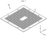
- FIG. 3 is a diagram illustrating the filter plate 20 according to an embodiment of the present disclosure
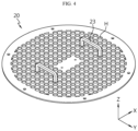
- FIG. 4 is a diagram illustrating the filter plate 20 according to another embodiment of the present disclosure
- FIG. 5 is a diagram illustrating the filter plate 20 according to still another embodiment of the present disclosure.
- the filter plate 20 may have at least one through-hole H.
- the through-hole H is a hole that passes through the filter plate and is not limited to a particular shape. That is, the through-hole H refers to a hole in the filter plate 20.
- the through-hole H may be a perforated hole. That is, the through-hole H of the filter plate 20 may be a hole formed by punching.
- the filter plate 20 was of a wire type.
- the filter plate 20 was a mesh formed by weaving wires on the horizontal axis and wires on the vertical axis.
- the filter plate 20 of the present disclosure is of a perforated-type, not a wire-type, to avoid friction between dissimilar metals when vibration occurs. Accordingly, it may be possible to prevent a risk of abrasion between dissimilar metals by the friction.
- the through-hole H may include a plurality of through-holes.
- the through-hole H may include a plurality of through-holes in the filter plate 20. More specifically, the through-hole H may include a plurality of through-holes in a regular arrangement in the filter plate 20.
- the through-hole H may be circular or quadrilateral in shape.
- the length of one side of the through-hole H may be set to about 20 mm.
- the width of an area between the through-holes H may be set to about 2 mm.
- the through-hole H may be hexagonal in shape.
- the through-hole H is not limited to a particular shape, and the shape of the through-hole H of the present disclosure may include any shape that may be formed by punching.
- the filter plate 20 may include at least one handle 23.
- the handle 23 protruding upward may be disposed on the filter plate 20.
- the handle 23 may be disposed at symmetrical locations with respect to an imaginary line passing through the center of the filter plate 20.
- the filter plate 20 may have an approximately circular plate shape.
- the filter plate 20 may have an approximately circular plate shape.
- the hopper 10 may have an approximately conic shape with the apex pointing down so that the cross section of the hopper 10 on which the filter plate 20 is mounted may be approximately circular in shape.
- the filter plate 20 may have an approximately quadrilateral plate shape.
- the hopper 10 may have an approximately quadrilateral pyramid shape with the apex pointing down so that the cross section of the hopper 10 on which the filter plate 20 is mounted may be approximately quadrilateral in shape.
- the shape of the filter plate 20 is not limited thereto, and plate shapes having various shapes may be included in the scope of the filter plate 20 of the present disclosure.
- the shape of the filter plate 20 and the shape of the through-hole H do not always match each other.
- the filter plate 20 may be circular in shape and the through-hole H may be circular in shape
- the filter plate 20 may be quadrilateral in shape and the through-hole H may be quadrilateral in shape.
- the filter plate 20 may be circular in shape and the through-hole H may be quadrilateral in shape. That is, the shape of the filter plate 20 and the shape of the through-hole H may be variously combined without affecting each other.
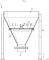
- FIG. 6 is a front view of the active material feeding device 1 according to an embodiment of the present disclosure
- FIG. 7 is an enlarged partial view of the active material feeding device 1 of FIG. 6 .
- the filter plate 20 may extend in a direction perpendicular to the depth direction of the hopper 10. That is, the hopper 10 may have an approximately conic shape extending in the vertical direction, and in this instance, the depth direction may be parallel to the vertical direction.
- the filter plate 20 may extend in the direction perpendicular to the depth direction of the hopper 10, i.e., the horizontal direction.
- the filter plate 20 may extend in a direction parallel to the ground.
- the active material may be uniformly distributed over the entire area of the filter plate 20. Accordingly, the active material may be discharged downward smoothly and efficiently through the plurality of through-holes H in the filter plate 20. Accordingly, by the above-described structure, it may be possible to prevent bottlenecks.
- the filter plate 20 may be disposed at the area between the inlet 11 and the outlet 12 of the hopper 10.
- the filter plate 20 may be located at about 1/2 point of the total depth of the hopper 10.
- the filter plate 20 may include a plurality of filter plates at the area between the inlet 11 and the outlet 12 of the hopper 10. By this embodiment, it may be possible to further improve the prevention effect of active material agglomeration.
- the active material feeding device 1 may include a plate holder 25 to fix the filter plate 20 at a predetermined location.
- the plate holder 25 may be fixed to the hopper 10.
- the side of the hopper 10 may decrease in diameter downwards, but may have a step structure including a specific area in which the diameter does not decrease and is constant, and a horizontally extended region toward the center of the hopper in the radial direction.
- the plate holder 25 may be configured to be mounted on the step of the hopper. Accordingly, the plate holder 25 may be stably mounted on the hopper 10.
- the plate holder 25 and the hopper 10 may be coupled by an additional coupling means.
- the coupling method is not limited to a particular one.
- the plate holder 25 may include an upper holder 251 disposed on the filter plate 20 and coupled to the hopper 10; and a lower holder 252 disposed below the filter plate 20 and coupled to the hopper 10.
- the lower holder 252 may support the bottom of the filter plate 20.
- a square bar may be applied to the bottom of the lower holder 252.
- the filter plate 20 may be mounted on the lower holder 252, and the upper holder 251 may be mounted on the filter plate 20. That is, the filter plate 20 may be fixed between the upper holder 251 and the lower holder 252.
- the upper holder 251 may be configured to prevent the filter plate 20 from escaping upwards. For example, because vibration of the vibrator 30 is transmitted to the filter plate 20, the upper holder 251 needs to fix the filter plate 20 to prevent the filter plate 20 from slipping away from the holder by the vibration.
- the upper holder 251 and the lower holder 252 are preferably coupled to each other. That is, the upper holder 251 and the lower holder 252 may be fixed to each other, for example, by screw coupling, with the filter plate 20 interposed between them.
- the coupling method is not limited thereto.
- the upper holder 251 and the lower holder 252 may have an O-ring groove 253 recessed inward at the edge.
- an O-ring R having elasticity may be inserted into the O-ring groove 253.
- the O-ring R may have, for example, a rim shape.
- the cross section of the O-ring R may be, for example, approximately semi-circular in shape as shown in FIG. 7 .
- the shape of the cross section of the O-ring R may change depending on the shape of the O-ring groove 253.
- the shape of the O-ring R in cross section may match the shape of the O-ring groove 253 in cross section.
- the O-ring R may include, for example, silicone.
- the O-ring R may include rubber. That is the O-ring R may include an elastic material.
- the O-ring R fixes the filter plate 20 at the predetermined location of the hopper 10 by a frictional force.
- a stopper may be applied to minimize the gap between the hopper 10 and the plate holder 25.
- FIG. 8 is a diagram illustrating the vibrator 30 disposed on the filter plate 20 according to an embodiment of the present disclosure
- FIG. 9 is a diagram illustrating the vibrator 30 disclosure on the filter plate 20 according to another embodiment of the present.
- FIG. 10 is a diagram illustrating the vibrator 30 according to an embodiment of the present disclosure.
- the vibrator 30 may be disposed at the inside area of the filter plate 20. That is, the vibrator 30 may be disposed in the space inside of the edge, not the edge area of the filter plate 20. Preferably, the vibrator 30 may be disposed at the central area of the filter plate 20.
- the filter plate 20 may have an approximately circular plate shape. In this instance, the vibrator 30 may be mounted at the center of the filter plate 20.
- vibration generated from the vibrator 30 may be uniformly transmitted to the filter plate 20.
- the vibration intensity is highest at the location at which the vibrator 30 is disposed and decreases as it is further away from the vibrator 30, and when the vibrator 30 is disposed at an end of the filter plate 20, the vibration intensity is highest at the location at which the vibrator 30 is disposed and is lowest at the furthest location from the vibrator 30, resulting in non-uniform vibration intensity at the edge area of the filter plate 20.
- the vibration intensity is highest at the central area of the filter plate 20 and decreases as it goes further in the radial direction, and vibration occurs at the same intensity over the entire edge of the filter plate 20.
- active material powder is fed into the hopper 10
- the largest amount of active material particles generally gather at the central area, so it is necessary to generate vibration of highest intensity at the central area.
- a smaller amount of active material particles gather at the edge area, so vibration of lower intensity may be sufficient to break active material agglomerates. Accordingly, by the present disclosure, it may be possible to prevent active material agglomeration and break active material agglomerates most efficiently.
- the vibrator 30 may include a plurality of vibrators in the inside area of the filter plate 20.
- the mounting location of the vibrator 30 may be set to generate vibration of uniform intensity over the entire filter plate 20.
- the vibrators 30 may be arranged at an interval of 120° in the inside area of the filter plate 20. By this configuration, it may be possible to generate vibration of uniform intensity over the entire area of the filter plate 20.
- the vibrator 30 may be coupled to the filter plate 20, for example, by welding.
- the vibrator 30 may be coupled to the filter plate 20 by bolting.
- the coupling method of the vibrator 30 and the filter plate 20 is not limited thereto.
- the vibrator 30 may be a machine that generates vibration.
- the vibrator 30 of the present disclosure may be, for example, an air turbine vibrator 30. That is, the vibrator 30 may generate vibration by rotating a rotary turbine gear in the machine by using compressed air.
- the vibrator 30 may include a support portion 31, a body portion 32, an inlet port 33 and an outlet port 34.
- the support portion 31 may support the vibrator 30, and the vibrator 30 may be fixed to the filter plate 20 through the support portion 31.
- the support portion 31 may be coupled to the filter plate 20, for example, by welding.
- the support portion 31 may be coupled to the filter plate 20 by bolting.
- the coupling method is not limited thereto and the vibrator 30 may be coupled to the filter plate 20 by a variety of coupling methods.
- the body portion 32 may include the rotary turbine gear included in the vibrator 30.
- the rotary turbine gear may be rotated by the compressed air.
- a vibrational force may be generated by the rotation of the rotary turbine gear, and accordingly, the vibration may be transmitted to the filter plate 20 connected through the support portion 31 of the vibrator 30.
- the compressed air may enter the body portion 32 of the vibrator 30 through the inlet port 33 of the vibrator 30.
- the compressed air may exit through the outlet port 34 by the rotation of the rotary turbine gear of the body portion 32.
- the inlet port 33 and the outlet port 34 may be disposed at the upper area of the vibrator 30.
- the inlet port 33 and the outlet port 34 may be connected to a hose that may move a fluid. A flow of fluid may be provided through the hose.
- the vibration output may be adjusted by adjusting the air pressure. That is, by the above-described configuration, the intensity of feeding the active material may be adjusted by adjusting the air pressure intensity. Additionally, by the above-described configuration, there is no gas explosion risk due to the use of air. Furthermore, by the vibrator 30 structure of the present disclosure, the vibrator 30 may have semi-permanent lifespan. However, the type of the vibrator 30 of the present disclosure is not limited thereto, and the vibrator 30 of the present disclosure may include any device that performs the vibration function.
- the support 40 may be configured to support the active material feeding device 1.
- the support 40 may include a plurality of supports on the perimeter of the active material feeding device 1.
- the support 40 may include at least three supports on the outer perimeter of the active material feeding device 1.
- the shape of the support 40 is not limited to a particular one, and may include, for example, a cylindrical shape or a quadrangular prism shape.
- the present disclosure may reduce the time taken to feed the active material through the installation of the vibrator 30.
- the time taken to feed was about 240 min, but when feeding into the active material feeding device 1 according to an embodiment of the present disclosure, the time taken to feed was reduced to about 170 min or less. That is, according to the present disclosure, the time taken to feed the single-crystal positive electrode active material was reduced by about 30% or more, compared to the conventional art. In particular, by the active material feeding device 1 of the present disclosure, when feeding 20kg of the specific active material, the feeding was completed within 2 min.
- the conventional active material feeding device needed to use a physical method to feed the active material due to arching or bridging of the active material, and fed the active material little by little.
- active material OT-H4S 750KG it took about 105 minutes to completely feed the active material.
- a delay in feeding the active material within the filter plate 20 did not occur, and because the intensity of feeding the active material can be adjusted according to the pneumatic pressure intensity, it was confirmed that on the basis of OT-H4S 750KG, it took about 80 minutes to completely feed the active material.
- the present disclosure for example, on the basis of OT-H4S 750KG, the time taken to feed the active material was reduced from about 105 minutes to about 80 minutes, i.e., by about 30%. Accordingly, it was confirmed that it was possible to effectively feed the single-crystal positive electrode active material through the application of the vibrator 30 in the filter plate 20, and adjust the intensity of feeding the active material according to the pneumatic pressure intensity. Additionally, by the present disclosure, as it is more effective in feeding the single-crystal positive electrode active material, it may be possible to ensure the LOB margin.
Landscapes
- Engineering & Computer Science (AREA)
- Mechanical Engineering (AREA)
- Manufacturing & Machinery (AREA)
- Chemical & Material Sciences (AREA)
- Chemical Kinetics & Catalysis (AREA)
- Electrochemistry (AREA)
- General Chemical & Material Sciences (AREA)
- Battery Electrode And Active Subsutance (AREA)
- Disintegrating Or Milling (AREA)
Abstract
Description
- The present disclosure relates to an active material feeding device.
- The present application claims priority to
Korean Patent Application No. 10-2023-0079222 filed on June 20, 2023 Korean Patent Application No. 10-2024-0025952 filed on February 22, 2024 - As secondary batteries can be easily applied to various types of products and have electrical properties such as high energy density, they are not only commonly used in portable devices but also universally applied to electric vehicles (EVs) or hybrid electric vehicles (HEVs) and electric scooters that are driven by an electrical driving source. Secondary batteries can remarkably reduce the use of fossil fuels. In addition to the primary advantage, another advantage is that they do not generate by-products from the use of energy. Due to these advantages, secondary batteries are gaining attention as a new eco-friendly and energy efficient source of energy.
- The types of secondary batteries widely used at present include lithium ion batteries, lithium polymer batteries, nickel cadmium batteries, nickel hydrogen batteries, nickel zinc batteries and so on. A unit secondary battery cell, i.e., a unit battery cell has an operating voltage of about 2.5V to 4.5V. Accordingly, when higher output voltage is required, a plurality of battery cells may be connected in series to form a battery pack. Additionally, the battery pack may be formed by connecting the plurality of battery cells in parallel according to the charge/discharge capacity required for the battery pack. Accordingly, the number of battery cells in the battery pack may be variously set depending on the required output voltage or charge/discharge capacity.
- Meanwhile, in the manufacture of secondary batteries, conventionally, when feeding single-crystal positive electrode active materials, blockage at meshes and delays in feeding occurred due to arching and bridging of the single-crystal active materials in feed hoppers. More specifically, it was necessary to deagglomerate active material agglomerates by human hand or feed the active materials using an air gun.
- An object of the present disclosure is to prevent active material agglomeration when feeding the active material.
- Another object of the present disclosure is to prevent delays in active material feeding.
- The technical problems of the present disclosure to be solved are not limited to the aforementioned problems, and these and other problems will be clearly understood by those skilled in the art from the following description.
- To solve the above-described problem, an active material feeding device according to an embodiment of the present disclosure includes a hopper configured to accommodate and transfer an active material; a filter plate disposed inside of the hopper and having at least one through-hole; and a vibrator disposed on at least part of the filter plate and configured to vibrate the filter plate.
- In an aspect of the present disclosure, the hopper may have an inclined surface and decrease in width downwards.
- In another aspect of the present disclosure, a cross section of the hopper may be circular in shape.
- In another aspect of the present disclosure, the through-hole may be a perforated hole.
- Preferably, the through-hole may include a plurality of through-holes.
- In an aspect of the present disclosure, the through-hole may be circular or quadrilateral in shape.
- In another aspect of the present disclosure, the filter plate may extend in a direction perpendicular to a depth direction of the hopper.
- In another aspect of the present disclosure, the filter plate may be located at a 1/2 point of a total depth of the hopper.
- In an aspect of the present disclosure, the active material feeding device may include a plate holder to fix the filter plate at a predetermined location.
- Here, the plate holder may include an upper holder disposed on the filter plate and coupled to the hopper; and a lower holder disposed below the filter plate and coupled to the hopper.
- Preferably, the filter plate may be fixed between the upper holder and the lower holder.
- In another aspect of the present disclosure, the upper holder and the lower holder may have an O-ring groove that is recessed inward at an edge, and an O-ring having elasticity may be inserted into the O-ring groove.
- In an aspect of the present disclosure, the vibrator may be disposed at a central area of the filter plate.
- In another aspect of the present disclosure, the vibrator may be coupled to the filter plate by welding.
- In another aspect of the present disclosure, the vibrator may be configured to rotate a rotary turbine gear in the vibrator by using compressed air.
- By the present disclosure, it may be possible to prevent active material agglomeration when feeding the active material.
- In another aspect, by the present disclosure, it may be possible to prevent delays in active material feeding.
- In particular, by the present disclosure, it may be possible to reduce the time taken to feed the single-crystal positive electrode active material by 30% or more.
- However, the effects that can be obtained through the present disclosure are not limited to the aforementioned effects, and these and other effects will be clearly understood by those skilled in the art from the following description.
- The accompanying drawings illustrate exemplary embodiments of the present disclosure and together with the following detailed description, serve to provide a further understanding of the technical aspect of the present disclosure, and thus, the present disclosure should not be construed as being limited to the drawings.
-
FIG. 1 is a diagram illustrating an active material feeding device according to an embodiment of the present disclosure. -
FIG. 2 is an exploded perspective view ofFIG. 1 . -
FIG. 3 is a diagram illustrating a filter plate according to an embodiment of the present disclosure. -
FIG. 4 is a diagram illustrating a filter plate according to another embodiment of the present disclosure. -
FIG. 5 is a diagram illustrating a filter plate according to still another embodiment of the present disclosure. -
FIG. 6 is a front view of an active material feeding device according to an embodiment of the present disclosure. -
FIG. 7 is an enlarged partial view of the active material feeding device ofFIG. 6 . -
FIG. 8 is a diagram illustrating a vibrator disposed on a filter plate according to an embodiment of the present disclosure. -
FIG. 9 is a diagram illustrating a vibrator disposed on a filter plate according to another embodiment of the present disclosure. -
FIG. 10 is a diagram illustrating a vibrator according to an embodiment of the present disclosure. - Hereinafter, exemplary embodiments of the present disclosure will be described in detail with reference to the accompanying drawings. Prior to the description, it should be understood that the terms or words used in the specification and the appended claims should not be construed as limited to general and dictionary meanings, but interpreted based on the meanings and concepts corresponding to the technical aspect of the present disclosure on the basis of the principle that the inventor is allowed to define terms appropriately for the best explanation. Therefore, the description provided herein and illustrations in the drawings are provided to describe some exemplary embodiments of the present disclosure, but not intended to fully describe the technical aspect of the present disclosure, so it should be understood that a variety of other equivalents and modifications could have been made thereto at the time of filing the patent application.
- Additionally, in order to help the understanding of the present disclosure, the accompanying drawings are not drawn to scale, and the dimensions of some elements may be exaggerated. Also, the same reference numerals may be affixed to the same elements in different embodiments.
- The term "same" may signify "substantially the same". Accordingly, "substantially the same" may include the same but having differences of, for example, 5% or less that is regarded as a low level in the corresponding technical field. Additionally, when a parameter is referred to as being uniform in a certain area, it may represent that the parameter is uniform in the ordinary sense.
- The terms "first", "second" and the like, are used to describe different elements, but these elements are not limited by the terms. The terms are used to distinguish one element from another, and unless otherwise stated, a first element may be a second element.
- Throughout the specification, unless otherwise stated, each element may be singular or plural.
- It should be understood that when an element is referred to as being "on (or below)", it can be present on an upper surface (or a lower surface), or intervening elements may be present between the element and other element disposed on (or below) the element.
- It should be further understood that when an element is referred to as being "connected to" or "coupled to" another element, it can be directly connected to the other element but each element may be "connected to" or "coupled to" each other through another element or intervening elements may be present.
- In the specification, "A and/or B" refers to either A or B or both unless otherwise stated, and "C to D" refers to C or more and D or less unless otherwise stated.
-
FIG. 1 is a diagram illustrating an activematerial feeding device 1 according to an embodiment of the present disclosure, andFIG. 2 is an exploded perspective view ofFIG. 1 . - Referring to
FIGs. 1 and2 , the activematerial feeding device 1 includes ahopper 10, afilter plate 20 and avibrator 30. The activematerial feeding device 1 may further include asupport 40. The activematerial feeding device 1 may be used to feed a single-crystal positive electrode active material. - More specifically, the
hopper 10 may be configured to accommodate and transfer the active material. For example, thehopper 10 may be configured to accommodate and transfer the single-crystal positive electrode active material. Thefilter plate 20 may be disposed inside of thehopper 10 and have at least one through-hole H. That is, the filter plate may act as a screen mesh to filter the active material loaded from thehopper 10. The size of the through-hole H of thefilter plate 20 may be larger than the particle size of the active material. That is, agglomerated active material particles cannot pass through the through-hole H and only non-agglomerated active material particles may pass through the through-hole H of thefilter plate 20. Thevibrator 30 may be disposed on at least part of thefilter plate 20 and configured to vibrate thefilter plate 20. That is, as thevibrator 30 is mounted on thefilter plate 20 to vibrate thefilter plate 20, the active material stuck on thefilter plate 20 may vibrate together. Accordingly, it may be possible to break active material agglomerates. - By this structure of the present disclosure, it may be possible to prevent agglomeration of the active material fed into the
hopper 10. Furthermore, it may be possible to break down active material agglomerates into active material particles by the vibration of thevibrator 30. That is, by the present disclosure, it may be possible to prevent active material arching and bridging. Accordingly, it may be easy for the active material particles to pass through thefilter plate 20. Accordingly, by the present disclosure, it may be possible to prevent blockage at the through-hole H of thefilter plate 20. Additionally, it may be possible to eliminate the need to manually break active material agglomerates through human hands or air guns, thereby preventing delays in active material feeding. - Referring back to
FIGs. 1 and2 , thehopper 10 may have an inclined surface and its width may decrease downwards. - For example, the
hopper 10 may have an approximately conic shape with the apex pointing down. In this instance, thehopper 10 may have a circular cross section. In this case, as thehopper 10 is circular in cross section, there may be a lower likelihood that the active material gathers and agglomerates at the corner than an angled cross section. However, the embodiment of the present disclosure is not limited thereto, and any shape of thehopper 10 having the inclined surface and the width decreasing downwards may be included in the scope of the present disclosure. For example, triangular, quadrilateral, pentagonal and hexagonal pyramid shapes may be included in the scope of the present disclosure. - In another aspect, the
hopper 10 may include aninlet 11 through which the active material enters and anoutlet 12 through which the active material exits. For example, referring toFIGs. 1 and2 , theinlet 11 may be disposed at a location of the largest diameter of thehopper 10. That is, theinlet 11 may be located at the topmost of thehopper 10. Thehopper 10 may decrease in diameter downwards. In this instance, theoutlet 12 may be disposed at a location of the smallest diameter of thehopper 10. That is, theoutlet 12 may be located at the bottommost of thehopper 10. -
FIG. 3 is a diagram illustrating thefilter plate 20 according to an embodiment of the present disclosure, andFIG. 4 is a diagram illustrating thefilter plate 20 according to another embodiment of the present disclosure.FIG. 5 is a diagram illustrating thefilter plate 20 according to still another embodiment of the present disclosure. - In an aspect of the present disclosure, the
filter plate 20 may have at least one through-hole H. The through-hole H is a hole that passes through the filter plate and is not limited to a particular shape. That is, the through-hole H refers to a hole in thefilter plate 20. - Preferably, the through-hole H may be a perforated hole. That is, the through-hole H of the
filter plate 20 may be a hole formed by punching. - For example, conventionally, the
filter plate 20 was of a wire type. For example, thefilter plate 20 was a mesh formed by weaving wires on the horizontal axis and wires on the vertical axis. However, when the wire-type filter plate 20 is applied, friction may occur between dissimilar wire metals by the vibration of thevibrator 30. There is a risk of abrasion between dissimilar metals by the friction. In contrast, thefilter plate 20 of the present disclosure is of a perforated-type, not a wire-type, to avoid friction between dissimilar metals when vibration occurs. Accordingly, it may be possible to prevent a risk of abrasion between dissimilar metals by the friction. - In another aspect of the present disclosure, the through-hole H may include a plurality of through-holes.
- For example, referring to
FIGs. 3 to 5 , the through-hole H may include a plurality of through-holes in thefilter plate 20. More specifically, the through-hole H may include a plurality of through-holes in a regular arrangement in thefilter plate 20. In this instance, the through-hole H may be circular or quadrilateral in shape. In an example, when the through-hole H is quadrilateral in shape, the length of one side of the through-hole H may be set to about 20 mm. In this instance, the width of an area between the through-holes H may be set to about 2 mm. Alternatively, the through-hole H may be hexagonal in shape. The through-hole H is not limited to a particular shape, and the shape of the through-hole H of the present disclosure may include any shape that may be formed by punching. - In another aspect of the present disclosure, the
filter plate 20 may include at least onehandle 23. - For example, referring to
FIG. 4 , thehandle 23 protruding upward may be disposed on thefilter plate 20. In the embodiment ofFIG. 4 , thehandle 23 may be disposed at symmetrical locations with respect to an imaginary line passing through the center of thefilter plate 20. - By this configuration of the present disclosure, it may be possible to allow an operator to manually vibrate the
handle 23 to generate additional vibration to thefilter plate 20 or make it easy to detach thefilter plate 20 through thehandle 23. - In another aspect of the present disclosure, the
filter plate 20 may have an approximately circular plate shape. For example, referring toFIGs. 3 and4 , thefilter plate 20 may have an approximately circular plate shape. In this case, thehopper 10 may have an approximately conic shape with the apex pointing down so that the cross section of thehopper 10 on which thefilter plate 20 is mounted may be approximately circular in shape. - Meanwhile, as another embodiment, referring to
FIG. 5 , thefilter plate 20 may have an approximately quadrilateral plate shape. In this case, thehopper 10 may have an approximately quadrilateral pyramid shape with the apex pointing down so that the cross section of thehopper 10 on which thefilter plate 20 is mounted may be approximately quadrilateral in shape. However, the shape of thefilter plate 20 is not limited thereto, and plate shapes having various shapes may be included in the scope of thefilter plate 20 of the present disclosure. - Furthermore, the shape of the
filter plate 20 and the shape of the through-hole H do not always match each other. For example, as shown inFIG. 3 , thefilter plate 20 may be circular in shape and the through-hole H may be circular in shape, and as shown inFIG. 5 , thefilter plate 20 may be quadrilateral in shape and the through-hole H may be quadrilateral in shape. Additionally, as shown inFIG. 8 , thefilter plate 20 may be circular in shape and the through-hole H may be quadrilateral in shape. That is, the shape of thefilter plate 20 and the shape of the through-hole H may be variously combined without affecting each other. -
FIG. 6 is a front view of the activematerial feeding device 1 according to an embodiment of the present disclosure, andFIG. 7 is an enlarged partial view of the activematerial feeding device 1 ofFIG. 6 . - Referring to
FIGs. 6 and7 , thefilter plate 20 may extend in a direction perpendicular to the depth direction of thehopper 10. That is, thehopper 10 may have an approximately conic shape extending in the vertical direction, and in this instance, the depth direction may be parallel to the vertical direction. Here, thefilter plate 20 may extend in the direction perpendicular to the depth direction of thehopper 10, i.e., the horizontal direction. When considering that the activematerial feeding device 1 is generally installed on the ground, thefilter plate 20 may extend in a direction parallel to the ground. - By this structure, the active material may be uniformly distributed over the entire area of the
filter plate 20. Accordingly, the active material may be discharged downward smoothly and efficiently through the plurality of through-holes H in thefilter plate 20. Accordingly, by the above-described structure, it may be possible to prevent bottlenecks. - In another aspect of the present disclosure, the
filter plate 20 may be disposed at the area between theinlet 11 and theoutlet 12 of thehopper 10. For example, referring toFIG. 6 , thefilter plate 20 may be located at about 1/2 point of the total depth of thehopper 10. By the structure in which thefilter plate 20 is disposed at the area between theinlet 11 and theoutlet 12 of thehopper 10, it may be possible to prevent agglomeration of the active material in thehopper 10. Additionally, it may be possible to prevent additional agglomeration of the active material while the active material is discharged through theoutlet 12 of thehopper 10 afterwards. In some cases, thefilter plate 20 may include a plurality of filter plates at the area between theinlet 11 and theoutlet 12 of thehopper 10. By this embodiment, it may be possible to further improve the prevention effect of active material agglomeration. - In another aspect of the present disclosure, the active
material feeding device 1 may include aplate holder 25 to fix thefilter plate 20 at a predetermined location. Theplate holder 25 may be fixed to thehopper 10. For example, the side of thehopper 10 may decrease in diameter downwards, but may have a step structure including a specific area in which the diameter does not decrease and is constant, and a horizontally extended region toward the center of the hopper in the radial direction. In this instance, theplate holder 25 may be configured to be mounted on the step of the hopper. Accordingly, theplate holder 25 may be stably mounted on thehopper 10. Further, to improve the fixing strength, theplate holder 25 and thehopper 10 may be coupled by an additional coupling means. The coupling method is not limited to a particular one. - In an aspect of the present disclosure, the
plate holder 25 may include anupper holder 251 disposed on thefilter plate 20 and coupled to thehopper 10; and alower holder 252 disposed below thefilter plate 20 and coupled to thehopper 10. - For example, referring to
FIG. 7 , thelower holder 252 may support the bottom of thefilter plate 20. In this instance, a square bar may be applied to the bottom of thelower holder 252. By this structure, it may be possible to prevent thelower holder 252 and thefilter plate 20 from escaping downwards. Meanwhile, thefilter plate 20 may be mounted on thelower holder 252, and theupper holder 251 may be mounted on thefilter plate 20. That is, thefilter plate 20 may be fixed between theupper holder 251 and thelower holder 252. - The
upper holder 251 may be configured to prevent thefilter plate 20 from escaping upwards. For example, because vibration of thevibrator 30 is transmitted to thefilter plate 20, theupper holder 251 needs to fix thefilter plate 20 to prevent thefilter plate 20 from slipping away from the holder by the vibration. In this instance, theupper holder 251 and thelower holder 252 are preferably coupled to each other. That is, theupper holder 251 and thelower holder 252 may be fixed to each other, for example, by screw coupling, with thefilter plate 20 interposed between them. However, the coupling method is not limited thereto. - In another aspect of the present disclosure, the
upper holder 251 and thelower holder 252 may have an O-ring groove 253 recessed inward at the edge. In this instance, an O-ring R having elasticity may be inserted into the O-ring groove 253. The O-ring R may have, for example, a rim shape. The cross section of the O-ring R may be, for example, approximately semi-circular in shape as shown inFIG. 7 . The shape of the cross section of the O-ring R may change depending on the shape of the O-ring groove 253. For example, the shape of the O-ring R in cross section may match the shape of the O-ring groove 253 in cross section. By this configuration, it may be possible to further enhance the coupling strength between theplate holder 25 and thehopper 10. - Meanwhile, the O-ring R may include, for example, silicone. Alternatively, the O-ring R may include rubber. That is the O-ring R may include an elastic material. Additionally, the O-ring R fixes the
filter plate 20 at the predetermined location of thehopper 10 by a frictional force. Meanwhile, in an embodiment of the activematerial feeding device 1 of the present disclosure, a stopper may be applied to minimize the gap between thehopper 10 and theplate holder 25. -
FIG. 8 is a diagram illustrating thevibrator 30 disposed on thefilter plate 20 according to an embodiment of the present disclosure, andFIG. 9 is a diagram illustrating thevibrator 30 disclosure on thefilter plate 20 according to another embodiment of the present.FIG. 10 is a diagram illustrating thevibrator 30 according to an embodiment of the present disclosure. - Referring to
FIGs. 8 to 10 , thevibrator 30 may be disposed at the inside area of thefilter plate 20. That is, thevibrator 30 may be disposed in the space inside of the edge, not the edge area of thefilter plate 20. Preferably, thevibrator 30 may be disposed at the central area of thefilter plate 20. For example, referring toFIG. 8 , thefilter plate 20 may have an approximately circular plate shape. In this instance, thevibrator 30 may be mounted at the center of thefilter plate 20. - By the structure in which the
vibrator 30 is disposed at the inside area of thefilter plate 20, not the edge area of thefilter plate 20, vibration generated from thevibrator 30 may be uniformly transmitted to thefilter plate 20. For example, the vibration intensity is highest at the location at which thevibrator 30 is disposed and decreases as it is further away from thevibrator 30, and when thevibrator 30 is disposed at an end of thefilter plate 20, the vibration intensity is highest at the location at which thevibrator 30 is disposed and is lowest at the furthest location from thevibrator 30, resulting in non-uniform vibration intensity at the edge area of thefilter plate 20. In contrast, when thevibrator 30 is disposed at the central area of thefilter plate 20, the vibration intensity is highest at the central area of thefilter plate 20 and decreases as it goes further in the radial direction, and vibration occurs at the same intensity over the entire edge of thefilter plate 20. Meanwhile, when active material powder is fed into thehopper 10, the largest amount of active material particles generally gather at the central area, so it is necessary to generate vibration of highest intensity at the central area. On the contrary, a smaller amount of active material particles gather at the edge area, so vibration of lower intensity may be sufficient to break active material agglomerates. Accordingly, by the present disclosure, it may be possible to prevent active material agglomeration and break active material agglomerates most efficiently. - As another embodiment of the present disclosure, referring to
FIG. 9 , thevibrator 30 may include a plurality of vibrators in the inside area of thefilter plate 20. In this case, the mounting location of thevibrator 30 may be set to generate vibration of uniform intensity over theentire filter plate 20. For example, referring toFIG. 9 , thevibrators 30 may be arranged at an interval of 120° in the inside area of thefilter plate 20. By this configuration, it may be possible to generate vibration of uniform intensity over the entire area of thefilter plate 20. - In another aspect of the present disclosure, the
vibrator 30 may be coupled to thefilter plate 20, for example, by welding. Alternatively, thevibrator 30 may be coupled to thefilter plate 20 by bolting. However, the coupling method of thevibrator 30 and thefilter plate 20 is not limited thereto. - In an aspect of the present disclosure, the
vibrator 30 may be a machine that generates vibration. Thevibrator 30 of the present disclosure may be, for example, anair turbine vibrator 30. That is, thevibrator 30 may generate vibration by rotating a rotary turbine gear in the machine by using compressed air. - Referring to FIG. 11, the
vibrator 30 may include asupport portion 31, abody portion 32, aninlet port 33 and anoutlet port 34. - The
support portion 31 may support thevibrator 30, and thevibrator 30 may be fixed to thefilter plate 20 through thesupport portion 31. Thesupport portion 31 may be coupled to thefilter plate 20, for example, by welding. Alternatively, thesupport portion 31 may be coupled to thefilter plate 20 by bolting. However, the coupling method is not limited thereto and thevibrator 30 may be coupled to thefilter plate 20 by a variety of coupling methods. - The
body portion 32 may include the rotary turbine gear included in thevibrator 30. The rotary turbine gear may be rotated by the compressed air. A vibrational force may be generated by the rotation of the rotary turbine gear, and accordingly, the vibration may be transmitted to thefilter plate 20 connected through thesupport portion 31 of thevibrator 30. - The compressed air may enter the
body portion 32 of thevibrator 30 through theinlet port 33 of thevibrator 30. The compressed air may exit through theoutlet port 34 by the rotation of the rotary turbine gear of thebody portion 32. Theinlet port 33 and theoutlet port 34 may be disposed at the upper area of thevibrator 30. Theinlet port 33 and theoutlet port 34 may be connected to a hose that may move a fluid. A flow of fluid may be provided through the hose. - By this structure, it may be possible to reduce the size of the
vibrator 30, simplify the structure and make it easy to install. Additionally, it may be possible to apply a low noise structure. Furthermore, the vibration output may be adjusted by adjusting the air pressure. That is, by the above-described configuration, the intensity of feeding the active material may be adjusted by adjusting the air pressure intensity. Additionally, by the above-described configuration, there is no gas explosion risk due to the use of air. Furthermore, by thevibrator 30 structure of the present disclosure, thevibrator 30 may have semi-permanent lifespan. However, the type of thevibrator 30 of the present disclosure is not limited thereto, and thevibrator 30 of the present disclosure may include any device that performs the vibration function. - Referring back to
FIG. 1 , thesupport 40 may be configured to support the activematerial feeding device 1. For example, thesupport 40 may include a plurality of supports on the perimeter of the activematerial feeding device 1. For example, thesupport 40 may include at least three supports on the outer perimeter of the activematerial feeding device 1. The shape of thesupport 40 is not limited to a particular one, and may include, for example, a cylindrical shape or a quadrangular prism shape. - By the above-described configuration of the present disclosure, the present disclosure may reduce the time taken to feed the active material through the installation of the
vibrator 30. Through the following experiment, it can be seen that with the perforated structure of thefilter plate 20 and thevibrator 30 of the present disclosure, it may be possible to prevent agglomeration of the active material and break active material agglomerates very well. - For example, when 500kg of specific active material is fed into the conventional active material feeding device, the time taken to feed was about 240 min, but when feeding into the active
material feeding device 1 according to an embodiment of the present disclosure, the time taken to feed was reduced to about 170 min or less. That is, according to the present disclosure, the time taken to feed the single-crystal positive electrode active material was reduced by about 30% or more, compared to the conventional art. In particular, by the activematerial feeding device 1 of the present disclosure, when feeding 20kg of the specific active material, the feeding was completed within 2 min. - In another experiment, the conventional active material feeding device needed to use a physical method to feed the active material due to arching or bridging of the active material, and fed the active material little by little. For example, on the basis of active material OT-H4S 750KG, it took about 105 minutes to completely feed the active material. In contrast, as a result of the experiment of feeding the active material using the active
material feeding device 1 of the present disclosure, a delay in feeding the active material within thefilter plate 20 did not occur, and because the intensity of feeding the active material can be adjusted according to the pneumatic pressure intensity, it was confirmed that on the basis of OT-H4S 750KG, it took about 80 minutes to completely feed the active material. That is, it was confirmed that by the present disclosure, for example, on the basis of OT-H4S 750KG, the time taken to feed the active material was reduced from about 105 minutes to about 80 minutes, i.e., by about 30%. Accordingly, it was confirmed that it was possible to effectively feed the single-crystal positive electrode active material through the application of thevibrator 30 in thefilter plate 20, and adjust the intensity of feeding the active material according to the pneumatic pressure intensity. Additionally, by the present disclosure, as it is more effective in feeding the single-crystal positive electrode active material, it may be possible to ensure the LOB margin. - Although the present disclosure has been hereinabove described by a limited number of embodiments and drawings, the present disclosure is not limited thereto, and it is obvious to those skilled in the art that a variety of changes and modifications may be made thereto within the technical aspect of the present disclosure and the appended claims and equivalents thereof.
-
- 1: Active material feeding device
- 10: Hopper
- 11: Inlet
- 12: Outlet
- 20: Filter plate
- H: Through-hole
- 23: Handle
- 25: Plate holder
- 251: Upper holder
- 252: Lower holder
- 253: O-ring groove
- R: O-ring
- 30: Vibrator
- 31: Support portion
- 32: Body portion
- 33: Inlet port
- 34: Outlet port
- 40: Support
Claims (15)
- An active material feeding device comprising:a hopper configured to accommodate and transfer an active material;a filter plate disposed inside of the hopper and having at least one through-hole; anda vibrator disposed on at least part of the filter plate and configured to vibrate the filter plate.
- The active material feeding device according to claim 1, wherein the hopper has an inclined surface and decreases in width downwards.
- The active material feeding device according to claim 1, wherein a cross section of the hopper is circular in shape.
- The active material feeding device according to claim 1, wherein the through-hole is a perforated hole.
- The active material feeding device according to claim 1, wherein the through-hole includes a plurality of through-holes.
- The active material feeding device according to claim 1, wherein the through-hole is circular or quadrilateral in shape.
- The active material feeding device according to claim 1, wherein the filter plate extends in a direction perpendicular to a depth direction of the hopper.
- The active material feeding device according to claim 1, wherein the filter plate is located at a 1/2 point of a total depth of the hopper.
- The active material feeding device according to claim 1, wherein the active material feeding device includes a plate holder to fix the filter plate at a predetermined location.
- The active material feeding device according to claim 9, wherein the plate holder includes:an upper holder disposed on the filter plate and coupled to the hopper; anda lower holder disposed below the filter plate and coupled to the hopper.
- The active material feeding device according to claim 10, wherein the filter plate is fixed between the upper holder and the lower holder.
- The active material feeding device according to claim 10, wherein the upper holder and the lower holder have an O-ring groove that is recessed inward at an edge, and an O-ring having elasticity is inserted into the O-ring groove.
- The active material feeding device according to claim 1, wherein the vibrator is disposed at a central area of the filter plate.
- The active material feeding device according to claim 1, wherein the vibrator is coupled to the filter plate by welding.
- The active material feeding device according to claim 1, wherein the vibrator is configured to rotate a rotary turbine gear in the vibrator by using compressed air.
Applications Claiming Priority (3)
| Application Number | Priority Date | Filing Date | Title |
|---|---|---|---|
| KR20230079222 | 2023-06-20 | ||
| KR1020240025952A KR20240177698A (en) | 2023-06-20 | 2024-02-22 | Active material input device |
| PCT/KR2024/003139 WO2024262744A1 (en) | 2023-06-20 | 2024-03-12 | Active material input device |
Publications (2)
| Publication Number | Publication Date |
|---|---|
| EP4570381A1 true EP4570381A1 (en) | 2025-06-18 |
| EP4570381A4 EP4570381A4 (en) | 2026-01-07 |
Family
ID=93935943
Family Applications (1)
| Application Number | Title | Priority Date | Filing Date |
|---|---|---|---|
| EP24826069.7A Pending EP4570381A4 (en) | 2023-06-20 | 2024-03-12 | ACTIVE MATERIAL INPUT DEVICE |
Country Status (4)
| Country | Link |
|---|---|
| EP (1) | EP4570381A4 (en) |
| JP (1) | JP2025541176A (en) |
| CN (1) | CN119677591A (en) |
| WO (1) | WO2024262744A1 (en) |
Family Cites Families (15)
| Publication number | Priority date | Publication date | Assignee | Title |
|---|---|---|---|---|
| JPH0719194U (en) * | 1990-12-29 | 1995-04-07 | 東洋自動機株式会社 | Input hopper of packaging machine |
| CH685291A5 (en) * | 1992-03-17 | 1995-05-31 | Findeva Ag | Pneumatic vibrator with turbine drive. |
| DE102008056369A1 (en) * | 2008-11-07 | 2010-05-12 | Itw Gema Gmbh | Cyclone separator and powder recovery device for a powder coating plant with a cyclone separator |
| KR101359494B1 (en) * | 2013-09-16 | 2014-02-11 | 주식회사 창성하이테크 | Vibrating screen |
| KR101601689B1 (en) * | 2014-05-22 | 2016-03-09 | 한국기계연구원 | Feeding apparatus of granule or micropowder |
| CN205257524U (en) * | 2015-11-24 | 2016-05-25 | 东莞市大能环保科技有限公司 | Fully enclosed spiral vibrating feeder |
| CN105366225A (en) * | 2015-12-03 | 2016-03-02 | 湖南三一路面机械有限公司 | Arch breaking device and stock bin |
| KR101997514B1 (en) * | 2017-12-06 | 2019-07-09 | (주)세원하드페이싱 | coating powder supplying apparatus having vibrating module |
| KR102113821B1 (en) * | 2018-09-20 | 2020-05-21 | 주식회사 진영정공 | Powder supply valve and powder providing device |
| KR102720826B1 (en) * | 2019-10-23 | 2024-10-24 | 엘지전자 주식회사 | Powder providing device) |
| KR102166039B1 (en) * | 2020-05-27 | 2020-10-16 | 이성해 | Battery raw material input device |
| KR20230079222A (en) | 2020-10-08 | 2023-06-05 | 인디언 스페이스 리서치 오거너제이션 | Lithium supercapacitor having set of negative and positive electrodes stacked or wound with separators |
| KR102732243B1 (en) * | 2021-07-30 | 2024-11-25 | 주식회사 저스템 | Device for drying and supplying fine powder |
| CN217043448U (en) * | 2022-03-08 | 2022-07-26 | 辽宁华益管业有限责任公司 | Simple harmonic vibration screen of feeding device |
| KR20240025952A (en) | 2022-08-19 | 2024-02-27 | 임병용 | Latex glove putting on device |
-
2024
- 2024-03-12 EP EP24826069.7A patent/EP4570381A4/en active Pending
- 2024-03-12 JP JP2025533300A patent/JP2025541176A/en active Pending
- 2024-03-12 WO PCT/KR2024/003139 patent/WO2024262744A1/en not_active Ceased
- 2024-03-12 CN CN202480003638.2A patent/CN119677591A/en active Pending
Also Published As
| Publication number | Publication date |
|---|---|
| CN119677591A (en) | 2025-03-21 |
| JP2025541176A (en) | 2025-12-18 |
| EP4570381A4 (en) | 2026-01-07 |
| WO2024262744A1 (en) | 2024-12-26 |
Similar Documents
| Publication | Publication Date | Title |
|---|---|---|
| CN204093549U (en) | Gegen tablets intellectuality with particle diameter selection and timing function crushes and screens device | |
| JP2020065986A (en) | Vibration screening machine | |
| CN213435484U (en) | Scrap treatment device for furniture processing | |
| CN115699435B (en) | Gas emission device and battery module and battery pack including the gas emission device | |
| CN115415153A (en) | Waste lithium battery material screening method based on air pressure loading assistance | |
| CN119677591A (en) | Active material feeding device | |
| CN221772821U (en) | A vibrating screen suitable for small parts | |
| CN110681572A (en) | Adjustable vibration excitation vibration screen box | |
| KR102356130B1 (en) | A metallic foreign object screening apparatus included in the cathode material using electromagnet | |
| CN201002879Y (en) | Activating feeder | |
| CN210762708U (en) | Discharge rail and separate arrangement device with pin springs | |
| CN210545500U (en) | Screening breaker | |
| CN201124166Y (en) | Walnut kernel screening machine | |
| CN218309320U (en) | Cable material granule screening plant | |
| CN208512738U (en) | A fully automatic crushing soil screening device | |
| CN210808747U (en) | Valve structure and feeder | |
| CN222411895U (en) | Fluoride salt feeding device for aluminum electrolysis | |
| CN218459775U (en) | Sorting device | |
| CN209646719U (en) | A kind of pulverizer discharging device | |
| CN219483319U (en) | Lithium battery recycling and sorting metal material device | |
| CN219003357U (en) | Metal particle magnetic separation device for recycling waste lithium batteries | |
| CN220663830U (en) | Spring separator | |
| CN212268708U (en) | Capsule directional arrangement device | |
| CN214765986U (en) | Rotary cutter granulator with screening function | |
| CN217120797U (en) | Elastomer material vibrating screen |
Legal Events
| Date | Code | Title | Description |
|---|---|---|---|
| STAA | Information on the status of an ep patent application or granted ep patent |
Free format text: STATUS: THE INTERNATIONAL PUBLICATION HAS BEEN MADE |
|
| PUAI | Public reference made under article 153(3) epc to a published international application that has entered the european phase |
Free format text: ORIGINAL CODE: 0009012 |
|
| STAA | Information on the status of an ep patent application or granted ep patent |
Free format text: STATUS: REQUEST FOR EXAMINATION WAS MADE |
|
| 17P | Request for examination filed |
Effective date: 20250313 |
|
| AK | Designated contracting states |
Kind code of ref document: A1 Designated state(s): AL AT BE BG CH CY CZ DE DK EE ES FI FR GB GR HR HU IE IS IT LI LT LU LV MC ME MK MT NL NO PL PT RO RS SE SI SK SM TR |
|
| A4 | Supplementary search report drawn up and despatched |
Effective date: 20251209 |
|
| RIC1 | Information provided on ipc code assigned before grant |
Ipc: B02C 23/02 20060101AFI20251203BHEP Ipc: H01M 4/36 20060101ALI20251203BHEP Ipc: H01M 4/04 20060101ALI20251203BHEP Ipc: B02C 17/16 20060101ALI20251203BHEP Ipc: B02C 17/14 20060101ALI20251203BHEP Ipc: H01M 4/02 20060101ALI20251203BHEP Ipc: B65G 69/08 20060101ALI20251203BHEP Ipc: B65G 69/14 20060101ALI20251203BHEP Ipc: B65G 69/12 20060101ALI20251203BHEP |