EP4570380A1 - Vertical roller mill and maintenance method for deceleration device - Google Patents
Vertical roller mill and maintenance method for deceleration device Download PDFInfo
- Publication number
- EP4570380A1 EP4570380A1 EP23852585.1A EP23852585A EP4570380A1 EP 4570380 A1 EP4570380 A1 EP 4570380A1 EP 23852585 A EP23852585 A EP 23852585A EP 4570380 A1 EP4570380 A1 EP 4570380A1
- Authority
- EP
- European Patent Office
- Prior art keywords
- stand
- rotary table
- circumferential direction
- roller
- roller mill
- Prior art date
- Legal status (The legal status is an assumption and is not a legal conclusion. Google has not performed a legal analysis and makes no representation as to the accuracy of the status listed.)
- Pending
Links
Images


Classifications
-
- B—PERFORMING OPERATIONS; TRANSPORTING
- B02—CRUSHING, PULVERISING, OR DISINTEGRATING; PREPARATORY TREATMENT OF GRAIN FOR MILLING
- B02C—CRUSHING, PULVERISING, OR DISINTEGRATING IN GENERAL; MILLING GRAIN
- B02C15/00—Disintegrating by milling members in the form of rollers or balls co-operating with rings or discs
- B02C15/007—Mills with rollers pressed against a rotary horizontal disc
-
- B—PERFORMING OPERATIONS; TRANSPORTING
- B02—CRUSHING, PULVERISING, OR DISINTEGRATING; PREPARATORY TREATMENT OF GRAIN FOR MILLING
- B02C—CRUSHING, PULVERISING, OR DISINTEGRATING IN GENERAL; MILLING GRAIN
- B02C15/00—Disintegrating by milling members in the form of rollers or balls co-operating with rings or discs
- B02C15/04—Mills with pressed pendularly-mounted rollers, e.g. spring pressed
Definitions
- the present disclosure relates to a vertical roller mill.
- the roller mill of PTL 1 has a rotary table, a plurality of crushing rollers, and a stand.
- the rotary table is located above a reduction device.
- the rotary table is driven by a rotary drive unit connected to the rotary table via the reduction device.
- the plurality of crushing rollers are arranged around the rotary table. Each of the crushing rollers is pressed against the rotary table by a pressing drive unit.
- the roller mill crushes the object by making it be caught between the rotary table and the plurality of crushing rollers.
- the stand supports the rotary table and the plurality of crushing rollers.
- the stand has an arm support and a push drive unit support.
- the push drive unit support supports the rotary table and the pressing drive unit.
- the push drive unit support is provided so that it surrounds the outside of the reduction device located below the rotary table.
- the arm support is provided above the push drive unit support.
- Each of arm supports is provided corresponding to each of the plurality of crushing rollers.
- the crushing roller is provided correspond to each arm support.
- the stand has the arm support and the push drive unit support, and is configured to have multiple tiers in the vertical direction to support the rotary table and the plurality of crushing rollers. Therefore, the structure of the stand is complicated.
- the present disclosure is made in view of the above circumstances, and is to realize a simple structure of a vertical roller mill.
- a vertical roller mill with the following configuration. That is, the vertical roller mill has a rotary table, a plurality of crushing rollers, a plurality of roller assemblies and a plurality of stands.
- the rotary table is rotatably provided.
- the crushing rollers are capable of crushing an object to be crushed by being pressed against the object on the rotary table.
- Each of the roller assemblies has the crushing roller.
- the stands are arranged around the rotary table and support the roller assemblies.
- the stands include a first stand.
- the first stand supports a plurality of the roller assemblies arranged adjacent to each other in a circumferential direction of the rotary table.
- the first stand has a plurality of stand legs and a beam.
- the stand legs extend vertically and are arranged in a pair in the circumferential direction of the rotary table.
- the beam connects upper parts of the stand legs in the circumferential direction of the rotary table.
- the first stand is configured in a gantry shape by the stand legs and the beam.
- a following maintenance method for a reduction device is provided. That is, this maintenance method of the reduction device is applied to a vertical roller mill having a rotary table, a plurality of crushing rollers, a plurality of roller assemblies, a plurality of stands and the reduction device.
- the rotary table is rotatably provided.
- the crushing rollers are capable of crushing an object to be crushed by being pressed against the object on the rotary table.
- Each of the roller assemblies has the crushing roller.
- the stands are arranged around the rotary table and support the roller assemblies.
- the reduction device reduces rotation input from a drive source and transmits the rotation to the rotary table.
- the stands include a first stand.
- the first stand supports a plurality of the roller assemblies arranged adjacent to each other in a circumferential direction of the rotary table.
- the first stand has a plurality of stand legs and a beam.
- the stand legs extend vertically and are arranged in a pair in the circumferential direction of the rotary table.
- the beam connects upper parts of the stand legs in the circumferential direction of the rotary table.
- the first stand is configured in a gantry shape by the stand legs and the beam.
- the maintenance method includes pulling the reduction device through an internal space of the first stand to an outside of the vertical roller mill.
- FIG. 1 is a cross-sectional view of the overall configuration of a vertical roller mill 1 according to one embodiment of the present disclosure.
- the vertical roller mill 1 shown in FIG. 1 is fixed to an installation surface 50, such as a factory floor.
- the vertical roller mill 1 is capable of crushing objects that are fed into it.
- the object to be crushed can include, but is not limited to, cement, slag, coal, or the like.
- the vertical roller mill 1 has a housing 11, a rotary table 12, a reduction device 13, a plurality of crushing rollers 14, a plurality of roller assemblies 15, a plurality of pressing drive units 16, a plurality of stands 20, and a classifier 17.
- the housing 11 is formed in a hollow shape.
- the rotary table 12 and the crushing rollers 14 are located inside the housing 11.
- the rotary table 12 is rotatably supported around a rotation axis extending in a vertical direction. This rotation axis can be said to be substantially a center of the vertical roller mill 1.
- the plurality of stands 20 are arranged to surround the rotary table 12 in a plan view.
- the rotary table 12 is rotated by an electric motor 31 which is a drive source.
- the electric motor 31 is located a short distance from the center of the vertical roller mill 1 and is fixed to the installation surface 50.
- the reduction device 13 is located below the rotary table 12 and fixed to the installation surface 50.
- the reduction device 13 can be configured as, for example, but not limited to, a planetary gear device.
- An input shaft of the reduction device 13 is connected to an output shaft of the electric motor 31 via a transmission shaft 32.
- the rotary table 12 is mounted on the output side of the reduction device 13.
- the rotation of the output shaft of the electric motor 31 is transmitted to the reduction device 13 via the transmission shaft 32.
- the reduction device 13 reduces the input rotation and transmits it to the rotary table 12. As a result, the rotary table 12 rotates.
- a feeding guide 33 formed in a cylindrical shape is provided above the rotary table 12.
- the feeding guide 33 can guide the object to be crushed onto the rotary table 12.
- the feeding guide 33 is arranged diagonally through the housing 11.
- the rotary table 12 is formed in a circular shape in the plan view.
- the rotary table 12 can receive on its top surface the object to be crushed that falls through the feeding guide 33.
- the plurality of crushing rollers 14 are arranged around the rotary table 12.
- the plurality of crushing rollers 14 are arranged so that they get on the periphery of the top surface of the rotary table 12.
- the plurality of crushing rollers 14 are arranged side by side in the circumferential direction of the rotary table 12.
- six of the crushing rollers 14 are arranged at equal angular intervals, but they may be arranged at unequal intervals.
- the circumferential direction of the rotary table 12 may be simply referred to as circumferential direction.
- Each of the crushing rollers 14 can be moved closer to or away from the periphery of the top surface of the rotary table 12 by the roller assembly 15 and the pressing drive unit 16. Each of the crushing rollers 14 is pressed against the object to be crushed on the rotary table 12 and crushes this object.
- the plurality of roller assemblies 15 are provided around the rotary table 12 so that each of them corresponds to each of the plurality of crushing rollers 14. Each of the plurality of roller assemblies 15 supports the crushing roller 14.
- Each roller assembly 15 has a first arm 51 and a second arm 52.
- the crushing roller 14 is attached to one end of the first arm 51.
- One end of the second arm 52 is connected to the other end of the first arm 51.
- the first arm 51 extends in a radial direction of the rotary table 12 in the plan view.
- the first arm 51 is supported by the stand 20 about a horizontal axis and can rotate with respect to the stand 20.
- the first arm 51 is arranged through the housing 11. Inside the housing 11, the crushing roller 14 is rotatably supported at the end of the first arm 51.
- the second arm 52 is provided so that it extends in a vertical direction. An intermediate portion of the second arm 52 in a longitudinal direction is rotatably supported about a horizontal axis with respect to the corresponding stand 20.
- the second arm 52 is located near the housing 11 and outside the housing 11.
- the second arm 52 is arranged near the end of the stand 20 in one side closer to the housing 11. Outside of the housing 11, the first arm 51 is connected to an upper end of the second arm 52.
- the pressing drive unit 16 is provided for each of the roller assemblies 15.
- the pressing drive unit 16 is located lower than the roller assembly 15.
- Each of the pressing drive units 16 can press the crushing rollers 14 against the rotary table 12 via the roller assembly 15.
- the pressing drive unit 16 is a hydraulic cylinder device in this embodiment. One end of the hydraulic cylinder is connected to a lower end of the second arm 52 and the other end is connected to the side of the installation surface 50. By extending and retracting the hydraulic cylinder, the crushing roller 14 can be moved closer to or farther away from the rotary table 12.
- the configuration of the pressing drive unit 16 is not limited to the hydraulic cylinder.
- the pressing drive unit 16 can strongly press the crushing rollers 14 against the rotary table 12.
- the object to be crushed fed to the rotary table 12 is crushed between the crushing rollers 14 and the rotary table 12.
- a hot air supply port 35 is provided at a lower part of the housing 11.
- a suitable hot air supply source is connected to the hot air supply port 35 via a duct not shown. The hot air supplied to the inside of the housing 11 from the hot air supply port 35 blows up the crushed material crushed at the rotary table 12.
- the classifier 17 is located above the rotary table 12.
- the classifier 17 can classify the crushed material blown up by the hot air.
- the classifier 17 has a separator 41 and a return guide 42.
- the separator 41 is located above the rotary table 12 in the housing 11.
- the separator 41 is driven by a separator drive unit 43 (for example, an electric motor).
- the return guide 42 is located between the rotary table 12 and the separator 41 in the vertical direction.
- the return guide 42 is formed in a funnel shape, with a lower opening facing the rotary table 12 and an upper opening facing the separator 41.
- a fine powder discharge duct 44 is located at an upper part of the housing 11.
- the separator 41 discharges the fine powder from the transferred crushed material, which is finer than a predetermined granularity (particle size), from the fine powder discharge duct 44.
- the remaining crushed material is returned to the rotary table 12 via the return guide 42 and is crushed again by the crushing rollers 14.
- the plurality of stands 20 are provided around the rotary table 12 (outside the housing 11) so that they correspond in position to the crushing rollers 14 respectively.
- Each of the stands 20 supports one or two roller assemblies 15.
- FIG. 2 is a diagonal view of a lower part of the vertical roller mill 1.
- the housing 11, the feeding guide 33, the return guide 42 and the like are omitted.
- the stands 20 are arranged in the circumferential direction with appropriate spacing so as to surround the rotary table 12 and the reduction device 13 in the plan view.
- the plurality of stands 20 are all constructed of concrete with embedded steel bars as reinforcement.
- This embodiment of the vertical roller mill 1 has five stands 20.
- Each of the stands 20 may hereinafter be referred to as first stand 21, second stand 22, third stand 23, fourth stand 24, and fifth stand 25 to identify each of them.
- the fifth stand 25 is formed generally in an isosceles triangular shape in the plan view.
- the fifth stand 25 supports one roller assembly 15.
- the fifth stand 25 has two stand legs 71 and one beam 72.
- the stand legs 71 and the beam 72 are formed integrally.
- the stand legs 71 are arranged in a pair spaced apart in the circumferential direction.
- the beam 72 is provided to connect upper ends of the pair of stand legs 71 each other in the circumferential direction.
- the pressing drive unit 16 is located below the beam 72 and between the stand leg 71 and the stand leg 71.
- a recess 73 is formed on the beam 72 in a side close to the rotary table 12. Inside this recess 73, the second arm 52 described above provided by the roller assembly 15 is arranged.
- the fifth stand 25 has a pair of the stand legs 71 and the beam 72 that connects the upper parts thereof. This gives the fifth stand 25 a gantry shape.
- the first stand 21 is substantially equivalent to two fifth stands 25 in one piece.
- the first stand 21 supports two roller assemblies 15 which are circumferentially adjacent.
- the first stand 21 has two stand legs 71 and one beam 74.
- the stand legs 71 and the beam 74 are formed integrally.
- the stand legs 71 are arranged in a pair spaced apart in the circumferential direction of the housing 11.
- the beam 74 is provided to connect upper ends of the pair of stand legs 71 each other.
- the beam 74 is bent to follow an outer circumference of the rotary table 12.
- the two pressing drive units 16 are located below the beam 74 and between the stand leg 71 and the stand leg 71. Furthermore, the transmission shaft 32 which transmits the drive power to the reduction device 13 is located between the two pressing drive units 16.
- Two recesses 73 are formed on the beam 74 in a side close to the rotary table 12. In each recess 73, the second arm 52 described above provided by the roller assembly 15 is arranged.
- roller assemblies 15 are located between the two stand legs 71.
- the second stand 22 With respect to the second stand 22, the third stand 23, the fourth stand 24 and the fifth stand 25, one roller assembly 15 is located between the two stand legs 71. This realizes an arrangement in which the stand leg 71 and the roller assembly 15 are in different phases each other in the plan view.
- the dimension of the first stand 21 are generally equal to the dimension of two other stands.
- the number of stand legs 71 is the same for the first stand 21 and the other stands. Therefore, by using the first stand 21, essentially two stand legs 71 can be omitted.
- the stand legs 71 of the first stand 21 are located at only two circumferential ends and no stand legs are provided in the intermediate position of the circumferential direction.
- the two roller assemblies 15 are arranged between the stand legs 71 which are provided at both ends in the circumferential direction in the first stand 21.
- the two roller assemblies 15 are arranged between, in the plan view, the stand leg 71 closest to this bisection point P1 on one side in the circumferential direction and the stand leg 71 closest to the bisection point P1 on the other side in the circumferential direction. That is, the beam 72 is provided between the stand leg 71 closest to the bisection point P1 on one side in the circumferential direction and the stand leg 71 closest to the bisection point P1 on the other side in the circumferential direction, and the two roller assemblies 15 are fixed to this common beam 72. No stand legs are located at an intermediate part of the beam 72 in the circumferential direction.
- one of the two roller assemblies 15 is located between the bisection point P1 and the stand leg 71 that is on circumferential one side and closest from this bisection point P1.
- the remaining one of the roller assemblies 15 is located between the bisection point P1 and the stand leg 71 that is on circumferential the other side and closest from this bisection point P1.
- the beam 74 of the first stand 21 is longer in the circumferential direction than the beam 72 of the other stands. Therefore, the circumferential dimension L1 of the internal space of the gantry-shaped first stand 21 (the space between the stand leg 71 and the stand leg 71) is also longer than the circumferential dimension L2 of the internal space in the other stands (L1 > L2).
- the space between the stand leg 71 and the stand leg 71 can be wider.
- this space is used to locate the transmission shaft 32 and the electric motor 31.
- the vertical roller mill 1 can be made compact as a whole.
- the above circumferential dimension L1 with respect to the internal space of the first stand 21 is slightly larger than the dimension L3 of the reduction device 13 shown in FIG. 3 (L1 > L3). Therefore, by detaching the pressing drive unit 16, the electric motor 31, the transmission shaft 32, and the like arranged at the first stand 21 and moving them to another location, the reduction device 13 can pass through the internal space of the first stand 21 as shown in FIG. 3 .
- the two stand legs 71 are located to sandwich the passage of the reduction device 13. As a result, the reduction device 13 can be extracted from the vertical roller mill 1 through the space below the beam 72 without having to be lifted, thus improving the efficiency of maintenance work.
- the reduction device 13 can be pulled out of the first stand 21 by passing through the gantry-shaped first stand 21.
- the reduction device is located much lower relative to the rotary table in order to extract the rotary table without interference between the reduction device and the stand.
- the space for the path for extracting the reduction device 13 to the outside can be secured inside the gantry-shaped first stand 21.
- the stand 20 with a simplified shape can be realized, and the connection structure between the reduction device 13 and the rotary table 12 can also be simplified.
- this embodiment of the vertical roller mill 1 has the rotary table 12, the plurality of crushing rollers 14, the plurality of roller assemblies 15, and the plurality of stands 20.
- the rotary table 12 is rotatably provided.
- the crushing rollers 14 are capable of crushing the object to be crushed by being pressed against the object on the rotary table 12.
- the plurality of crushing rollers 14 are provided corresponding to the roller assemblies 15.
- the stands 20 are arranged around the rotary table 12 and support the roller assemblies 15.
- the stands 20 include the first stand 21.
- the first stand 21 supports the plurality of roller assemblies 15 that are arranged adjacent to each other in the circumferential direction of the rotary table 12.
- the first stand 21 has the plurality of stand legs 71 and the beam 74.
- the stand legs 71 are provided to extend vertically and are arranged in a pair in the circumferential direction of the rotary table 12.
- the beam 74 connects the upper parts of the stand legs 71 each other in the circumferential direction of the rotary table 12.
- the first stand 21 is configured in a gantry shape by the stand legs 71 and the beam 74.
- the stand 20 as a whole can be configured in a simplified manner, since the plurality of roller assemblies 15 can be supported by the single first stand 21.
- the internal space of the gantry-shaped first stand 21 can be wide enough to be easily utilized to accommodate various components.
- the plurality of roller assemblies 15 are arranged between the stand leg 71 on one side in the circumferential direction closest from the bisection point P1 of the circumferential length of the first stand 21 and the stand leg 71 on the other side in the circumferential direction closest from the bisection point P1.
- the first stand 21 supports two the roller assemblies 15.
- the vertical roller mill 1 of this embodiment has the reduction device 13 that reduces the rotation input from the drive source and transmits it to the rotary table 12.
- the dimension L1 between the stand legs 71 in the first stand 21 is larger than the dimension L3 of the reduction device 13.
- the first stand 21 is made of a material including concrete.
- the stand legs 71 are often formed in the shape of thick columns. Therefore, by configuring to support a plurality of roller assemblies 15, as in the first stand 21, a large space can be obtained by omitting the stand legs 71, which is advantageous.
- the number of the roller assemblies 15 is six.
- the circumferential spacing of the plurality of roller assemblies 15 becomes smaller. In such a case, it is suitable to support a plurality of roller assemblies 15 by one stand, such as the first stand 21, because it simplifies the configuration of the stand 20.
- maintenance of the reduction device 13 includes pulling the reduction device 13 through the internal space of the first stand 21 to the outside of the vertical roller mill 1.
- the number of multiple crushing rollers 14 (in other words, the number of roller assemblies 15) is six, but is not limited to this.
- the number of crushing rollers 14 can be two or more.
- the plurality of stands 20 are made of concrete, but can alternatively be made of steel, for example.
- the first stand 21 supports two roller assemblies 15 adjacent to each other in the circumferential direction of the rotary table 12, but it may support more than two roller assemblies 15.
- the number of stand legs 71 of the first stand 21 is two, but it is not limited to this and can be four, for example. However, it is preferred that all stand legs 71 are located at the circumferential ends of the first stand 21.
- the configuration of the second stand 22, the third stand 23, the fourth stand 24 and the fifth stand 25 is arbitrary.
- FIG. 3 shows this connecting part 80 by chain lines.
- the vertical roller mill 1 may be equipped with a circulation path that discharges the coarse grains of the crushed object and leads them to the feeding guide 33.
- a discharge conveyor constituting this circulation path can be located below the connecting part 80.
- the second stand 22 and the third stand 23 can be omitted and a stand similar to the first stand 21 can be arranged instead.
- the thickness of the beam 74 in the first stand 21 may be larger than the thickness of the beam 72 in the other stands.
Landscapes
- Engineering & Computer Science (AREA)
- Food Science & Technology (AREA)
- Crushing And Grinding (AREA)
Abstract
Description
- The present disclosure relates to a vertical roller mill.
- Vertical roller mills for milling objects to be crushed have been known in the past.
PTL 1 discloses this type of vertical roller mill. - The roller mill of
PTL 1 has a rotary table, a plurality of crushing rollers, and a stand. The rotary table is located above a reduction device. The rotary table is driven by a rotary drive unit connected to the rotary table via the reduction device. The plurality of crushing rollers are arranged around the rotary table. Each of the crushing rollers is pressed against the rotary table by a pressing drive unit. The roller mill crushes the object by making it be caught between the rotary table and the plurality of crushing rollers. - The stand supports the rotary table and the plurality of crushing rollers. In detail, the stand has an arm support and a push drive unit support. The push drive unit support supports the rotary table and the pressing drive unit. The push drive unit support is provided so that it surrounds the outside of the reduction device located below the rotary table. The arm support is provided above the push drive unit support. Each of arm supports is provided corresponding to each of the plurality of crushing rollers. The crushing roller is provided correspond to each arm support.
- PTL 1:
Japanese Patent No. 5809708 - In the configuration of
PTL 1, the stand has the arm support and the push drive unit support, and is configured to have multiple tiers in the vertical direction to support the rotary table and the plurality of crushing rollers. Therefore, the structure of the stand is complicated. - The present disclosure is made in view of the above circumstances, and is to realize a simple structure of a vertical roller mill.
- The problem to be solved by the present disclosure is as described above, and next, means for solving the problem and effects thereof will be described.
- According to the first aspect of the present disclosure, a vertical roller mill with the following configuration is provided. That is, the vertical roller mill has a rotary table, a plurality of crushing rollers, a plurality of roller assemblies and a plurality of stands. The rotary table is rotatably provided. The crushing rollers are capable of crushing an object to be crushed by being pressed against the object on the rotary table. Each of the roller assemblies has the crushing roller. The stands are arranged around the rotary table and support the roller assemblies. The stands include a first stand. The first stand supports a plurality of the roller assemblies arranged adjacent to each other in a circumferential direction of the rotary table. The first stand has a plurality of stand legs and a beam. The stand legs extend vertically and are arranged in a pair in the circumferential direction of the rotary table. The beam connects upper parts of the stand legs in the circumferential direction of the rotary table. The first stand is configured in a gantry shape by the stand legs and the beam.
- This allows the stands to have a simple structure since the plurality of stands are formed in a gantry shape.
- According to the second aspect of the present disclosure, a following maintenance method for a reduction device is provided. That is, this maintenance method of the reduction device is applied to a vertical roller mill having a rotary table, a plurality of crushing rollers, a plurality of roller assemblies, a plurality of stands and the reduction device. The rotary table is rotatably provided. The crushing rollers are capable of crushing an object to be crushed by being pressed against the object on the rotary table. Each of the roller assemblies has the crushing roller. The stands are arranged around the rotary table and support the roller assemblies. The reduction device reduces rotation input from a drive source and transmits the rotation to the rotary table. The stands include a first stand. The first stand supports a plurality of the roller assemblies arranged adjacent to each other in a circumferential direction of the rotary table. The first stand has a plurality of stand legs and a beam. The stand legs extend vertically and are arranged in a pair in the circumferential direction of the rotary table. The beam connects upper parts of the stand legs in the circumferential direction of the rotary table. The first stand is configured in a gantry shape by the stand legs and the beam. The maintenance method includes pulling the reduction device through an internal space of the first stand to an outside of the vertical roller mill.
- According to the present disclosure, a simplified structure of the vertical roller mill can be achieved.
-
-
FIG. 1 is a cross-sectional view of the overall configuration of a vertical roller mill according to one embodiment of the present disclosure. -
FIG. 2 is a diagonal view showing the lower part of the vertical roller mill. -
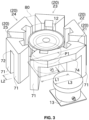
FIG. 3 is a diagonal view showing the reduction device being pulled out of the lower part of the vertical roller mill for maintenance. - Next, an embodiment of the present disclosure will be described with reference to the drawings.
FIG. 1 is a cross-sectional view of the overall configuration of avertical roller mill 1 according to one embodiment of the present disclosure. - The
vertical roller mill 1 shown inFIG. 1 is fixed to aninstallation surface 50, such as a factory floor. Thevertical roller mill 1 is capable of crushing objects that are fed into it. The object to be crushed can include, but is not limited to, cement, slag, coal, or the like. - The
vertical roller mill 1 has ahousing 11, a rotary table 12, areduction device 13, a plurality of crushingrollers 14, a plurality ofroller assemblies 15, a plurality of pressingdrive units 16, a plurality ofstands 20, and aclassifier 17. - The
housing 11 is formed in a hollow shape. The rotary table 12 and the crushingrollers 14 are located inside thehousing 11. - The rotary table 12 is rotatably supported around a rotation axis extending in a vertical direction. This rotation axis can be said to be substantially a center of the
vertical roller mill 1. The plurality ofstands 20 are arranged to surround the rotary table 12 in a plan view. - The rotary table 12 is rotated by an
electric motor 31 which is a drive source. Theelectric motor 31 is located a short distance from the center of thevertical roller mill 1 and is fixed to theinstallation surface 50. - The
reduction device 13 is located below the rotary table 12 and fixed to theinstallation surface 50. Thereduction device 13 can be configured as, for example, but not limited to, a planetary gear device. - An input shaft of the
reduction device 13 is connected to an output shaft of theelectric motor 31 via atransmission shaft 32. The rotary table 12 is mounted on the output side of thereduction device 13. - In this configuration, the rotation of the output shaft of the
electric motor 31 is transmitted to thereduction device 13 via thetransmission shaft 32. Thereduction device 13 reduces the input rotation and transmits it to the rotary table 12. As a result, the rotary table 12 rotates. - A feeding
guide 33 formed in a cylindrical shape is provided above the rotary table 12. The feedingguide 33 can guide the object to be crushed onto the rotary table 12. The feedingguide 33 is arranged diagonally through thehousing 11. - The rotary table 12 is formed in a circular shape in the plan view. The rotary table 12 can receive on its top surface the object to be crushed that falls through the feeding
guide 33. The plurality of crushingrollers 14 are arranged around the rotary table 12. - The plurality of crushing
rollers 14 are arranged so that they get on the periphery of the top surface of the rotary table 12. The plurality of crushingrollers 14 are arranged side by side in the circumferential direction of the rotary table 12. In this embodiment, six of the crushingrollers 14 are arranged at equal angular intervals, but they may be arranged at unequal intervals. In the following, the circumferential direction of the rotary table 12 may be simply referred to as circumferential direction. - Each of the crushing
rollers 14 can be moved closer to or away from the periphery of the top surface of the rotary table 12 by theroller assembly 15 and thepressing drive unit 16. Each of the crushingrollers 14 is pressed against the object to be crushed on the rotary table 12 and crushes this object. - The plurality of
roller assemblies 15 are provided around the rotary table 12 so that each of them corresponds to each of the plurality of crushingrollers 14. Each of the plurality ofroller assemblies 15 supports the crushingroller 14. - Each
roller assembly 15 has afirst arm 51 and asecond arm 52. The crushingroller 14 is attached to one end of thefirst arm 51. One end of thesecond arm 52 is connected to the other end of thefirst arm 51. - The
first arm 51 extends in a radial direction of the rotary table 12 in the plan view. Thefirst arm 51 is supported by thestand 20 about a horizontal axis and can rotate with respect to thestand 20. - The
first arm 51 is arranged through thehousing 11. Inside thehousing 11, the crushingroller 14 is rotatably supported at the end of thefirst arm 51. - The
second arm 52 is provided so that it extends in a vertical direction. An intermediate portion of thesecond arm 52 in a longitudinal direction is rotatably supported about a horizontal axis with respect to the correspondingstand 20. - The
second arm 52 is located near thehousing 11 and outside thehousing 11. Thesecond arm 52 is arranged near the end of thestand 20 in one side closer to thehousing 11. Outside of thehousing 11, thefirst arm 51 is connected to an upper end of thesecond arm 52. - The
pressing drive unit 16 is provided for each of theroller assemblies 15. Thepressing drive unit 16 is located lower than theroller assembly 15. Each of thepressing drive units 16 can press the crushingrollers 14 against the rotary table 12 via theroller assembly 15. - The
pressing drive unit 16 is a hydraulic cylinder device in this embodiment. One end of the hydraulic cylinder is connected to a lower end of thesecond arm 52 and the other end is connected to the side of theinstallation surface 50. By extending and retracting the hydraulic cylinder, the crushingroller 14 can be moved closer to or farther away from the rotary table 12. However, the configuration of thepressing drive unit 16 is not limited to the hydraulic cylinder. - The
pressing drive unit 16 can strongly press the crushingrollers 14 against the rotary table 12. The object to be crushed fed to the rotary table 12 is crushed between the crushingrollers 14 and the rotary table 12. - A hot
air supply port 35 is provided at a lower part of thehousing 11. A suitable hot air supply source is connected to the hotair supply port 35 via a duct not shown. The hot air supplied to the inside of thehousing 11 from the hotair supply port 35 blows up the crushed material crushed at the rotary table 12. - The
classifier 17 is located above the rotary table 12. Theclassifier 17 can classify the crushed material blown up by the hot air. - The
classifier 17 has aseparator 41 and areturn guide 42. - The
separator 41 is located above the rotary table 12 in thehousing 11. Theseparator 41 is driven by a separator drive unit 43 (for example, an electric motor). - The return guide 42 is located between the rotary table 12 and the
separator 41 in the vertical direction. The return guide 42 is formed in a funnel shape, with a lower opening facing the rotary table 12 and an upper opening facing theseparator 41. - A fine
powder discharge duct 44 is located at an upper part of thehousing 11. Theseparator 41 discharges the fine powder from the transferred crushed material, which is finer than a predetermined granularity (particle size), from the finepowder discharge duct 44. The remaining crushed material is returned to the rotary table 12 via thereturn guide 42 and is crushed again by the crushingrollers 14. - The plurality of
stands 20 are provided around the rotary table 12 (outside the housing 11) so that they correspond in position to the crushingrollers 14 respectively. Each of thestands 20 supports one or tworoller assemblies 15. - Next, the plurality of
stands 20 will be described in detail with reference toFIG. 2. FIG. 2 is a diagonal view of a lower part of thevertical roller mill 1. InFIG. 2 , thehousing 11, the feedingguide 33, thereturn guide 42 and the like are omitted. - The stands 20 are arranged in the circumferential direction with appropriate spacing so as to surround the rotary table 12 and the
reduction device 13 in the plan view. The plurality ofstands 20 are all constructed of concrete with embedded steel bars as reinforcement. - This embodiment of the
vertical roller mill 1 has five stands 20. Each of thestands 20 may hereinafter be referred to asfirst stand 21,second stand 22,third stand 23,fourth stand 24, andfifth stand 25 to identify each of them. - Since the
second stand 22, thethird stand 23, thefourth stand 24, and thefifth stand 25 all have the same configuration, thefifth stand 25 will be described hereinafter as representative. - As shown in
FIG. 2 , thefifth stand 25 is formed generally in an isosceles triangular shape in the plan view. Thefifth stand 25 supports oneroller assembly 15. - The
fifth stand 25 has twostand legs 71 and onebeam 72. Thestand legs 71 and thebeam 72 are formed integrally. - The
stand legs 71 are arranged in a pair spaced apart in the circumferential direction. Thebeam 72 is provided to connect upper ends of the pair ofstand legs 71 each other in the circumferential direction. - The
pressing drive unit 16 is located below thebeam 72 and between thestand leg 71 and thestand leg 71. - A
recess 73 is formed on thebeam 72 in a side close to the rotary table 12. Inside thisrecess 73, thesecond arm 52 described above provided by theroller assembly 15 is arranged. - As described above, the
fifth stand 25 has a pair of thestand legs 71 and thebeam 72 that connects the upper parts thereof. This gives the fifth stand 25 a gantry shape. - The
first stand 21 is substantially equivalent to twofifth stands 25 in one piece. Thefirst stand 21 supports tworoller assemblies 15 which are circumferentially adjacent. - The
first stand 21 has twostand legs 71 and onebeam 74. Thestand legs 71 and thebeam 74 are formed integrally. - The
stand legs 71 are arranged in a pair spaced apart in the circumferential direction of thehousing 11. Thebeam 74 is provided to connect upper ends of the pair ofstand legs 71 each other. Thebeam 74 is bent to follow an outer circumference of the rotary table 12. - The two
pressing drive units 16 are located below thebeam 74 and between thestand leg 71 and thestand leg 71. Furthermore, thetransmission shaft 32 which transmits the drive power to thereduction device 13 is located between the twopressing drive units 16. - Two
recesses 73 are formed on thebeam 74 in a side close to the rotary table 12. In eachrecess 73, thesecond arm 52 described above provided by theroller assembly 15 is arranged. - With respect to the
first stand 21, tworoller assemblies 15 are located between the two standlegs 71. With respect to thesecond stand 22, thethird stand 23, thefourth stand 24 and thefifth stand 25, oneroller assembly 15 is located between the two standlegs 71. This realizes an arrangement in which thestand leg 71 and theroller assembly 15 are in different phases each other in the plan view. - Next, the
first stand 21 will be described in detail. - As described above, in the circumferential direction of the rotary table 12, the dimension of the
first stand 21 are generally equal to the dimension of two other stands. On the other hand, the number ofstand legs 71 is the same for thefirst stand 21 and the other stands. Therefore, by using thefirst stand 21, essentially two standlegs 71 can be omitted. - The
stand legs 71 of thefirst stand 21 are located at only two circumferential ends and no stand legs are provided in the intermediate position of the circumferential direction. The tworoller assemblies 15 are arranged between thestand legs 71 which are provided at both ends in the circumferential direction in thefirst stand 21. - Considering the bisection point P1 of the circumferential length of the
first stand 21, the tworoller assemblies 15 are arranged between, in the plan view, thestand leg 71 closest to this bisection point P1 on one side in the circumferential direction and thestand leg 71 closest to the bisection point P1 on the other side in the circumferential direction. That is, thebeam 72 is provided between thestand leg 71 closest to the bisection point P1 on one side in the circumferential direction and thestand leg 71 closest to the bisection point P1 on the other side in the circumferential direction, and the tworoller assemblies 15 are fixed to thiscommon beam 72. No stand legs are located at an intermediate part of thebeam 72 in the circumferential direction. - In the plan view, one of the two
roller assemblies 15 is located between the bisection point P1 and thestand leg 71 that is on circumferential one side and closest from this bisection point P1. The remaining one of theroller assemblies 15 is located between the bisection point P1 and thestand leg 71 that is on circumferential the other side and closest from this bisection point P1. - The
beam 74 of thefirst stand 21 is longer in the circumferential direction than thebeam 72 of the other stands. Therefore, the circumferential dimension L1 of the internal space of the gantry-shaped first stand 21 (the space between thestand leg 71 and the stand leg 71) is also longer than the circumferential dimension L2 of the internal space in the other stands (L1 > L2). - Therefore, in the
first stand 21, the space between thestand leg 71 and thestand leg 71 can be wider. In this embodiment, this space is used to locate thetransmission shaft 32 and theelectric motor 31. As a result, thevertical roller mill 1 can be made compact as a whole. - In this embodiment, the above circumferential dimension L1 with respect to the internal space of the
first stand 21 is slightly larger than the dimension L3 of thereduction device 13 shown inFIG. 3 (L1 > L3). Therefore, by detaching thepressing drive unit 16, theelectric motor 31, thetransmission shaft 32, and the like arranged at thefirst stand 21 and moving them to another location, thereduction device 13 can pass through the internal space of thefirst stand 21 as shown inFIG. 3 . The two standlegs 71 are located to sandwich the passage of thereduction device 13. As a result, thereduction device 13 can be extracted from thevertical roller mill 1 through the space below thebeam 72 without having to be lifted, thus improving the efficiency of maintenance work. - Thus, in this embodiment of the
vertical roller mill 1, thereduction device 13 can be pulled out of thefirst stand 21 by passing through the gantry-shapedfirst stand 21. - In the configuration of
PTL 1, the reduction device is located much lower relative to the rotary table in order to extract the rotary table without interference between the reduction device and the stand. In this embodiment, the space for the path for extracting thereduction device 13 to the outside can be secured inside the gantry-shapedfirst stand 21. Thus, thestand 20 with a simplified shape can be realized, and the connection structure between thereduction device 13 and the rotary table 12 can also be simplified. - As explained above, this embodiment of the
vertical roller mill 1 has the rotary table 12, the plurality of crushingrollers 14, the plurality ofroller assemblies 15, and the plurality of stands 20. The rotary table 12 is rotatably provided. The crushingrollers 14 are capable of crushing the object to be crushed by being pressed against the object on the rotary table 12. The plurality of crushingrollers 14 are provided corresponding to theroller assemblies 15. The stands 20 are arranged around the rotary table 12 and support theroller assemblies 15. The stands 20 include thefirst stand 21. Thefirst stand 21 supports the plurality ofroller assemblies 15 that are arranged adjacent to each other in the circumferential direction of the rotary table 12. Thefirst stand 21 has the plurality ofstand legs 71 and thebeam 74. Thestand legs 71 are provided to extend vertically and are arranged in a pair in the circumferential direction of the rotary table 12. Thebeam 74 connects the upper parts of thestand legs 71 each other in the circumferential direction of the rotary table 12. Thefirst stand 21 is configured in a gantry shape by thestand legs 71 and thebeam 74. - This allows the
stand 20 as a whole to be configured in a simplified manner, since the plurality ofroller assemblies 15 can be supported by the singlefirst stand 21. In addition, the internal space of the gantry-shaped first stand 21 can be wide enough to be easily utilized to accommodate various components. - In this embodiment of the
vertical roller mill 1, the plurality ofroller assemblies 15 are arranged between thestand leg 71 on one side in the circumferential direction closest from the bisection point P1 of the circumferential length of thefirst stand 21 and thestand leg 71 on the other side in the circumferential direction closest from the bisection point P1. - This allows for a larger internal space in the circumferential center of the
first stand 21. - In this embodiment of the
vertical roller mill 1, thefirst stand 21 supports two theroller assemblies 15. - This allows for a simplified configuration of the
first stand 21. - The
vertical roller mill 1 of this embodiment has thereduction device 13 that reduces the rotation input from the drive source and transmits it to the rotary table 12. The dimension L1 between thestand legs 71 in thefirst stand 21 is larger than the dimension L3 of thereduction device 13. - This allows the
reduction device 13 to be extracted to the outside of thevertical roller mill 1 by passing through the internal space of thefirst stand 21. Thus, maintenance of thereduction device 13 becomes easier. - In this embodiment of the
vertical roller mill 1, thefirst stand 21 is made of a material including concrete. - This helps to suppress vibrations and impacts that occur when the objects to be crushed are crushed by being caught between the plurality of crushing
rollers 14 and the rotary table 12. In theconcrete stand 20, thestand legs 71 are often formed in the shape of thick columns. Therefore, by configuring to support a plurality ofroller assemblies 15, as in thefirst stand 21, a large space can be obtained by omitting thestand legs 71, which is advantageous. - In this embodiment of the
vertical roller mill 1, the number of theroller assemblies 15 is six. - In the case where
many roller assemblies 15 are arranged, the circumferential spacing of the plurality ofroller assemblies 15 becomes smaller. In such a case, it is suitable to support a plurality ofroller assemblies 15 by one stand, such as thefirst stand 21, because it simplifies the configuration of thestand 20. - In this embodiment of the
vertical roller mill 1, maintenance of thereduction device 13 includes pulling thereduction device 13 through the internal space of thefirst stand 21 to the outside of thevertical roller mill 1. - This facilitates maintenance of the
reduction device 13. - While some preferred embodiments of the present disclosure have been described above, the foregoing configurations may be modified, for example, as follows.
- In the above embodiment, the number of multiple crushing rollers 14 (in other words, the number of roller assemblies 15) is six, but is not limited to this. The number of crushing
rollers 14 can be two or more. - In the above embodiment, the plurality of
stands 20 are made of concrete, but can alternatively be made of steel, for example. - In the above embodiment, the
first stand 21 supports tworoller assemblies 15 adjacent to each other in the circumferential direction of the rotary table 12, but it may support more than tworoller assemblies 15. - In the above embodiment, the number of
stand legs 71 of thefirst stand 21 is two, but it is not limited to this and can be four, for example. However, it is preferred that all standlegs 71 are located at the circumferential ends of thefirst stand 21. - The configuration of the
second stand 22, thethird stand 23, thefourth stand 24 and thefifth stand 25 is arbitrary. - For example, the top of the
third stand 23 and the top of thefourth stand 24 can be connected and integrated.FIG. 3 shows this connectingpart 80 by chain lines. Thevertical roller mill 1 may be equipped with a circulation path that discharges the coarse grains of the crushed object and leads them to the feedingguide 33. A discharge conveyor constituting this circulation path can be located below the connectingpart 80. - For example, the
second stand 22 and thethird stand 23 can be omitted and a stand similar to thefirst stand 21 can be arranged instead. The same is true for thefourth stand 24 and thefifth stand 25. - Taking into account the difference in span lengths of the
beams beam 74 in thefirst stand 21 may be larger than the thickness of thebeam 72 in the other stands. - In light of the above teachings, it is clear that the present disclosure can take many modified and variant forms. Accordingly, it is to be understood that the present disclosure may be implemented in ways other than those described herein within the scope of the appended claims.
- From the above disclosure, at least the following technical ideas can be ascertained.
- (Item 1) A vertical roller mill comprising:
- a rotary table rotatably provided;
- a plurality of crushing rollers capable of crushing an object to be crushed by being pressed against the object on the rotary table;
- a plurality of roller assemblies, each of which has the crushing roller; and
- a plurality of stands arranged around the rotary table and supporting the roller assemblies,
- wherein
- the stands include a first stand supporting a plurality of the roller assemblies arranged adjacent to each other in a circumferential direction of the rotary table,
- the first stand includes:
- a plurality of stand legs extending vertically and arranged in a pair in the circumferential direction of the rotary table; and
- a beam connecting upper parts of the stand legs in the circumferential direction of the rotary table, and
- the first stand is configured in a gantry shape by the stand legs and the beam.
- (Item 2) The vertical roller mill according to
item 1, wherein
a plurality of the roller assemblies are arranged in a plan view between the stand leg on one side in the circumferential direction closest from a bisection point of the circumferential length of the first stand and the stand leg on the other side in the circumferential direction closest from the bisection point. - (Item 3) The vertical roller mill according to
items 1 or 2, wherein,
the first stand supports two the roller assemblies. - (Item 4) The vertical roller mill according to item 3, comprising:
- a reduction device that reduces rotation input from a drive source and transmits the rotation to the rotary table, wherein
- a dimension between the stand legs of the first stand is larger than a dimension of the reduction device.
- (Item 5) The vertical roller mill according to any one of
items 1 to 4, wherein
the first stand comprises a material including concrete. - (Item 6) The vertical roller mill according to any one of
items 1 to 5, wherein
a number of the roller assemblies is six or more. - (Item 7) The vertical roller mill according to any one of
items 1 to 6, wherein
the stand leg and the roller assembly of the first stand are arranged such that the stand leg and the roller assembly are in different phases with each other. - (Item 8) A maintenance method for a reduction device of a vertical roller mill comprising:
- a rotary table rotatably provided;
- a plurality of crushing rollers capable of crushing an object to be crushed by being pressed against the object on the rotary table;
- a plurality of roller assemblies, each of which has the crushing roller;
- a plurality of stands arranged around the rotary table and supporting the roller assemblies; and
- the reduction device that reduces rotation input from a drive source and transmits the rotation to the rotary table,
- wherein
- the stands include a first stand supporting a plurality of the roller assemblies arranged adjacent to each other in a circumferential direction of the rotary table,
- the first stand includes:
- a plurality of stand legs extending vertically and arranged in a pair in the circumferential direction of the rotary table; and
- a beam connecting upper parts of the stand legs in the circumferential direction of the rotary table,
- the first stand is configured in a gantry shape by the stand legs and the beam, and
- the maintenance method includes pulling the reduction device through an internal space of the first stand to an outside of the vertical roller mill.
Claims (8)
- A vertical roller mill comprising:a rotary table rotatably provided;a plurality of crushing rollers capable of crushing an object to be crushed by being pressed against the object on the rotary table;a plurality of roller assemblies, each of which has the crushing roller; anda plurality of stands arranged around the rotary table and supporting the roller assemblies,whereinthe stands include a first stand supporting a plurality of the roller assemblies arranged adjacent to each other in a circumferential direction of the rotary table,the first stand includes:a plurality of stand legs extending vertically and arranged in a pair in the circumferential direction of the rotary table; anda beam connecting upper parts of the stand legs in the circumferential direction of the rotary table, andthe first stand is configured in a gantry shape by the stand legs and the beam.
- The vertical roller mill according to claim 1, wherein
a plurality of the roller assemblies are arranged in a plan view between the stand leg on one side in the circumferential direction closest from a bisection point of the circumferential length of the first stand and the stand leg on the other side in the circumferential direction closest from the bisection point. - The vertical roller mill according to claim 1, wherein
the first stand supports two the roller assemblies. - The vertical roller mill according to claim 3, comprising:a reduction device that reduces rotation input from a drive source and transmits the rotation to the rotary table, whereina dimension between the stand legs of the first stand is larger than a dimension of the reduction device.
- The vertical roller mill according to claim 1, wherein
the first stand comprises a material including concrete. - The vertical roller mill according to claim 1, wherein
a number of the roller assemblies is six or more. - The vertical roller mill according to claim 1, wherein
the stand leg and the roller assembly of the first stand are arranged such that the stand leg and the roller assembly are in different phases with each other. - A maintenance method for a reduction device of a vertical roller mill comprising:a rotary table rotatably provided;a plurality of crushing rollers capable of crushing an object to be crushed by being pressed against the object on the rotary table;a plurality of roller assemblies, each of which has the crushing roller;a plurality of stands arranged around the rotary table and supporting the roller assemblies; andthe reduction device that reduces rotation input from a drive source and transmits the rotation to the rotary table,whereinthe stands include a first stand supporting a plurality of the roller assemblies arranged adjacent to each other in a circumferential direction of the rotary table,the first stand includes:a plurality of stand legs extending vertically and arranged in a pair in the circumferential direction of the rotary table; anda beam connecting upper parts of the stand legs in the circumferential direction of the rotary table,the first stand is configured in a gantry shape by the stand legs and the beam, andthe maintenance method includes pulling the reduction device through an internal space of the first stand to an outside of the vertical roller mill.
Applications Claiming Priority (2)
| Application Number | Priority Date | Filing Date | Title |
|---|---|---|---|
| JP2022127482A JP2024024559A (en) | 2022-08-09 | 2022-08-09 | Maintenance method for vertical roller mill and reduction gear |
| PCT/JP2023/029007 WO2024034623A1 (en) | 2022-08-09 | 2023-08-08 | Vertical roller mill and maintenance method for deceleration device |
Publications (2)
| Publication Number | Publication Date |
|---|---|
| EP4570380A1 true EP4570380A1 (en) | 2025-06-18 |
| EP4570380A4 EP4570380A4 (en) | 2026-08-12 |
Family
ID=89851876
Family Applications (1)
| Application Number | Title | Priority Date | Filing Date |
|---|---|---|---|
| EP23852585.1A Pending EP4570380A4 (en) | 2022-08-09 | 2023-08-08 | VERTICAL ROLLER MILL AND MAINTENANCE PROCEDURES FOR DELAY DEVICE |
Country Status (4)
| Country | Link |
|---|---|
| EP (1) | EP4570380A4 (en) |
| JP (1) | JP2024024559A (en) |
| CN (1) | CN119698327A (en) |
| WO (1) | WO2024034623A1 (en) |
Family Cites Families (11)
| Publication number | Priority date | Publication date | Assignee | Title |
|---|---|---|---|---|
| JPS5836651A (en) * | 1981-08-27 | 1983-03-03 | 住友セメント株式会社 | Shaft type crushing apparatus |
| DE3801728C2 (en) * | 1988-01-21 | 1998-07-02 | Krupp Polysius Ag | Roller mill |
| DE102005030145B4 (en) * | 2005-06-28 | 2007-10-04 | Loesche Gmbh | Safety system for a roller mill |
| JP4965984B2 (en) * | 2006-12-04 | 2012-07-04 | 川崎重工業株式会社 | Vertical roller mill |
| DE102008015142A1 (en) * | 2008-03-20 | 2009-09-24 | Gebr. Pfeiffer Ag | roller mill |
| JP5345004B2 (en) * | 2009-06-15 | 2013-11-20 | 川崎重工業株式会社 | Vertical roller mill |
| JP5809708B2 (en) | 2011-11-11 | 2015-11-11 | 川崎重工業株式会社 | Vertical roller mill |
| CN104056691B (en) * | 2013-03-21 | 2018-01-12 | 川崎重工业株式会社 | Vertical roll grinder |
| DE102014000549B4 (en) * | 2014-01-15 | 2020-07-02 | Renk Aktiengesellschaft | Housing for a drive arrangement of a vertical roller mill |
| JP6678061B2 (en) * | 2016-04-25 | 2020-04-08 | 川崎重工業株式会社 | Vertical roller mill |
| EP3727697B1 (en) * | 2019-01-17 | 2022-04-27 | Loesche GmbH | Roll lever module |
-
2022
- 2022-08-09 JP JP2022127482A patent/JP2024024559A/en active Pending
-
2023
- 2023-08-08 CN CN202380058551.0A patent/CN119698327A/en active Pending
- 2023-08-08 EP EP23852585.1A patent/EP4570380A4/en active Pending
- 2023-08-08 WO PCT/JP2023/029007 patent/WO2024034623A1/en not_active Ceased
Also Published As
| Publication number | Publication date |
|---|---|
| CN119698327A (en) | 2025-03-25 |
| EP4570380A4 (en) | 2026-08-12 |
| WO2024034623A1 (en) | 2024-02-15 |
| JP2024024559A (en) | 2024-02-22 |
Similar Documents
| Publication | Publication Date | Title |
|---|---|---|
| US10556237B2 (en) | Device and method for ore-crushing with recycling | |
| EP2777814B1 (en) | Vertical roller mill | |
| US6557790B2 (en) | Circuit grinding apparatus with high-pressure roller mill and sifter | |
| EP0812622A2 (en) | Crusher | |
| US8651405B2 (en) | Roller mill | |
| JPH0889828A (en) | Mill reducer and mill equipped with this reducer | |
| US11679964B2 (en) | System, method and apparatus for servicing a pulverizer | |
| AU2017248526B2 (en) | Comminuting plant with a comminuting machine | |
| US4013235A (en) | Pulverizer hydraulic drive | |
| JP2024024559A (en) | Maintenance method for vertical roller mill and reduction gear | |
| US20130341449A1 (en) | Anvil unit for a material reducing machine | |
| US4288040A (en) | Low profile crushing apparatus | |
| KR20220040952A (en) | Impact Cone Crusher | |
| EP3159060B1 (en) | Vertical roller mill | |
| EP3863767B1 (en) | Hammer mill for milling refuse | |
| CN218902094U (en) | Mining cage crusher | |
| JP5345004B2 (en) | Vertical roller mill | |
| CN208963984U (en) | A kind of charging gear | |
| CN223915517U (en) | Two-stage ring hammer crusher | |
| CN220460778U (en) | Vertical mill grinding roller convenient to overhaul | |
| US20260021490A1 (en) | Gyratory crusher, a method for rotating an upper crusher frame and a retrofitting kit | |
| CN208449572U (en) | A kind of stagewise crushing plant with novel base | |
| JPS6043776B2 (en) | Grinding equipment | |
| KR20220040948A (en) | Concrasha with multistage mantle structure | |
| CN109095132A (en) | A kind of charging gear |
Legal Events
| Date | Code | Title | Description |
|---|---|---|---|
| STAA | Information on the status of an ep patent application or granted ep patent |
Free format text: STATUS: THE INTERNATIONAL PUBLICATION HAS BEEN MADE |
|
| PUAI | Public reference made under article 153(3) epc to a published international application that has entered the european phase |
Free format text: ORIGINAL CODE: 0009012 |
|
| STAA | Information on the status of an ep patent application or granted ep patent |
Free format text: STATUS: REQUEST FOR EXAMINATION WAS MADE |
|
| 17P | Request for examination filed |
Effective date: 20250307 |
|
| AK | Designated contracting states |
Kind code of ref document: A1 Designated state(s): AL AT BE BG CH CY CZ DE DK EE ES FI FR GB GR HR HU IE IS IT LI LT LU LV MC ME MK MT NL NO PL PT RO RS SE SI SK SM TR |
|
| DAV | Request for validation of the european patent (deleted) | ||
| DAX | Request for extension of the european patent (deleted) | ||
| A4 | Supplementary search report drawn up and despatched |
Effective date: 20260710 |
|
| RIC1 | Information provided on ipc code assigned before grant |
Ipc: B02C 15/04 20060101AFI20260709BHEP Ipc: B02C 15/00 20060101ALI20260709BHEP |