EP4570158A1 - Cup washer - Google Patents
Cup washer Download PDFInfo
- Publication number
- EP4570158A1 EP4570158A1 EP24156235.4A EP24156235A EP4570158A1 EP 4570158 A1 EP4570158 A1 EP 4570158A1 EP 24156235 A EP24156235 A EP 24156235A EP 4570158 A1 EP4570158 A1 EP 4570158A1
- Authority
- EP
- European Patent Office
- Prior art keywords
- additive
- pump
- supply pipe
- inlet
- supply
- Prior art date
- Legal status (The legal status is an assumption and is not a legal conclusion. Google has not performed a legal analysis and makes no representation as to the accuracy of the status listed.)
- Pending
Links
Images




Classifications
-
- A—HUMAN NECESSITIES
- A47—FURNITURE; DOMESTIC ARTICLES OR APPLIANCES; COFFEE MILLS; SPICE MILLS; SUCTION CLEANERS IN GENERAL
- A47L—DOMESTIC WASHING OR CLEANING; SUCTION CLEANERS IN GENERAL
- A47L15/00—Washing or rinsing machines for crockery or tableware
- A47L15/0065—Washing or rinsing machines for crockery or tableware specially adapted for drinking glasses
-
- A—HUMAN NECESSITIES
- A47—FURNITURE; DOMESTIC ARTICLES OR APPLIANCES; COFFEE MILLS; SPICE MILLS; SUCTION CLEANERS IN GENERAL
- A47L—DOMESTIC WASHING OR CLEANING; SUCTION CLEANERS IN GENERAL
- A47L15/00—Washing or rinsing machines for crockery or tableware
- A47L15/42—Details
- A47L15/4246—Details of the tub
-
- A—HUMAN NECESSITIES
- A47—FURNITURE; DOMESTIC ARTICLES OR APPLIANCES; COFFEE MILLS; SPICE MILLS; SUCTION CLEANERS IN GENERAL
- A47L—DOMESTIC WASHING OR CLEANING; SUCTION CLEANERS IN GENERAL
- A47L15/00—Washing or rinsing machines for crockery or tableware
- A47L15/42—Details
- A47L15/44—Devices for adding cleaning agents; Devices for dispensing cleaning agents, rinsing aids or deodorants
-
- A—HUMAN NECESSITIES
- A47—FURNITURE; DOMESTIC ARTICLES OR APPLIANCES; COFFEE MILLS; SPICE MILLS; SUCTION CLEANERS IN GENERAL
- A47L—DOMESTIC WASHING OR CLEANING; SUCTION CLEANERS IN GENERAL
- A47L15/00—Washing or rinsing machines for crockery or tableware
- A47L15/42—Details
- A47L15/44—Devices for adding cleaning agents; Devices for dispensing cleaning agents, rinsing aids or deodorants
- A47L15/4418—Devices for adding cleaning agents; Devices for dispensing cleaning agents, rinsing aids or deodorants in the form of liquids
-
- A—HUMAN NECESSITIES
- A47—FURNITURE; DOMESTIC ARTICLES OR APPLIANCES; COFFEE MILLS; SPICE MILLS; SUCTION CLEANERS IN GENERAL
- A47L—DOMESTIC WASHING OR CLEANING; SUCTION CLEANERS IN GENERAL
- A47L15/00—Washing or rinsing machines for crockery or tableware
- A47L15/42—Details
- A47L15/44—Devices for adding cleaning agents; Devices for dispensing cleaning agents, rinsing aids or deodorants
- A47L15/449—Metering controlling devices
-
- F—MECHANICAL ENGINEERING; LIGHTING; HEATING; WEAPONS; BLASTING
- F04—POSITIVE - DISPLACEMENT MACHINES FOR LIQUIDS; PUMPS FOR LIQUIDS OR ELASTIC FLUIDS
- F04B—POSITIVE-DISPLACEMENT MACHINES FOR LIQUIDS; PUMPS
- F04B43/00—Machines, pumps, or pumping installations having flexible working members
- F04B43/12—Machines, pumps, or pumping installations having flexible working members having peristaltic action
- F04B43/1238—Machines, pumps, or pumping installations having flexible working members having peristaltic action using only one roller as the squeezing element, the roller moving on an arc of a circle during squeezing
- F04B43/1246—Machines, pumps, or pumping installations having flexible working members having peristaltic action using only one roller as the squeezing element, the roller moving on an arc of a circle during squeezing the roller being placed at the outside of the tubular flexible member
-
- A—HUMAN NECESSITIES
- A47—FURNITURE; DOMESTIC ARTICLES OR APPLIANCES; COFFEE MILLS; SPICE MILLS; SUCTION CLEANERS IN GENERAL
- A47L—DOMESTIC WASHING OR CLEANING; SUCTION CLEANERS IN GENERAL
- A47L2401/00—Automatic detection in controlling methods of washing or rinsing machines for crockery or tableware, e.g. information provided by sensors entered into controlling devices
- A47L2401/02—Consumable products information, e.g. information on detergent, rinsing aid or salt; Dispensing device information, e.g. information on the type, e.g. detachable, or status of the device
-
- A—HUMAN NECESSITIES
- A47—FURNITURE; DOMESTIC ARTICLES OR APPLIANCES; COFFEE MILLS; SPICE MILLS; SUCTION CLEANERS IN GENERAL
- A47L—DOMESTIC WASHING OR CLEANING; SUCTION CLEANERS IN GENERAL
- A47L2501/00—Output in controlling method of washing or rinsing machines for crockery or tableware, i.e. quantities or components controlled, or actions performed by the controlling device executing the controlling method
- A47L2501/07—Consumable products, e.g. detergent, rinse aids or salt
-
- F—MECHANICAL ENGINEERING; LIGHTING; HEATING; WEAPONS; BLASTING
- F04—POSITIVE - DISPLACEMENT MACHINES FOR LIQUIDS; PUMPS FOR LIQUIDS OR ELASTIC FLUIDS
- F04B—POSITIVE-DISPLACEMENT MACHINES FOR LIQUIDS; PUMPS
- F04B43/00—Machines, pumps, or pumping installations having flexible working members
- F04B43/08—Machines, pumps, or pumping installations having flexible working members having tubular flexible members
- F04B43/09—Pumps having electric drive
Definitions
- the present disclosure relates to a cup washer, and more specifically, to a cup washer that washes a cup by spraying water.
- a cup washer is a device that washes a cup by spraying water. Recently, as the awareness of practicing carbon neutrality has expanded throughout society, the number of people carrying personal or reusable cups has increased. Accordingly, the number of government offices, companies, and stores where cup washers are installed for the hygiene and convenience of users (employees) is increasing.
- Korean Patent No. 2114048 discloses a "compact automatic cup washer” which includes a housing, a support pad, a rotating frame, an external nozzle, an external brush, a sterilizing and drying unit, a detergent storage unit, and a pipe opening and closing unit.
- the pipe opening and closing unit includes a first valve configured to open and close a supply pipe through which washing water is supplied, and athird valve configured to open and close a passage between the detergent storage unit and the supply pipe.
- the detergent storage unit is a tank in which a liquid detergent is stored.
- Patent Publication No. WO2023/274943 discloses a "dishwasher detergent dispenser".
- the dishwasher detergent dispenser is installed in a dishwasher.
- the detergent dispenser is installed on the inner wall of the door.
- the detergent dispenser includes a housing compartment, a supply container, and a delivery mechanism (a pump unit or a pump driver).
- the pump driver and the housing compartment are first coupled to the inner wall of the door, and then the supply container is coupled to the housing compartment. At this time, the pump unit is coupled between the supply vessel and the housing compartment.
- the supply container defines a space inside which the detergent is filled (hereinafter, referred to as a "filling space").
- the pump driver includes an electric motor and a drive shaft.
- the pump unit includes a flexible tube, a rotor, and a plurality of pump elements (a plurality of rollers).
- the pump elements connected to the drive shaft rotate to pressurize the flexible tube, and the detergent in the flexible tube flows out into the washing chamber.
- the inlet and outlet of the pump unit are located below the drive shaft, and the upper portion of the flexible tube is higher than the lower portion of the filling space. Therefore, the detergent in the filling space rises along the flexible tube, then falls, and then flows out into the washing chamber. Therefore, when the height of the detergent in the filling space is lower than the upper portion of the flexible tube, all of the detergent in the filling space may not flow out into the washing chamber through the flexible tube, and the remaining amount may remain in the filling space and the lower portion of the flexible tube.
- the pump driver, the housing compartment, the pump unit, and the supply container are sequentially assembled to the inner wall of the door. Therefore, to repair or replace the pump driver, it is necessary to remove all of the housing compartment, the pump unit, and the supply container from the inner wall of the door. Therefore, it takes a long time to maintain the pump driver. Additionally, when the pump unit is separated during this process, there is a possibility that some of the detergent may leak out from the inlet and outlet of the pump unit.
- the amount of detergent that flows out into the washing chamber through a flexible tube is generally proportional to the rotation amount of a pump element (roller).
- the amount of detergent flowing into the washing chamber is controlled by controlling the operation (time) of the electric motor. Therefore, there are limitations in precisely controlling the amount of the detergent flowing into the washing chamber.
- the present disclosure is to solve the above-described problems of a cup washer that washes a cup by spraying water.
- the present disclosure is to provide a cup washer in which an additive storage and input structure is optimized such that the entire additive stored therein can be introduced into a pump and the entire additive discharged by the pump can be put into a tub.
- the present disclosure is to provide a cup washer in which a pump assembly structure is simplified and optimized so that the pump can be more easily and efficiently maintained and managed.
- the present disclosure is to provide a cup washer in which the amount of pressurization of a tube can be correctly monitored and the amount of the additive to be put into the tub can be precisely controlled.
- the present application discloses a cup washer that washes cups by spraying water into a tub, wherein the cup washer may include an additive storage part and an additive supply part.
- the additive storage part may store an additive in the storage space.
- the additive supply part may supply the additive into a tub.
- the additive supply part may include an additive pump and a first additive supply pipe.
- the additive pump may be placed below the additive storage part.
- the first additive supply pipe may connect the lower portion of the additive storage part to the inlet to provide a first supply passage through which the additive of the additive storage part moves toward the inlet of the additive pump.
- the first additive supply pipe and the inlet may be connected at a predetermined angle.
- the additive supply part may include a pump housing.
- the pump housing is located lower than the bottom of the storage space and may accommodate an additive pump therein.
- the first additive supply pipe may be coupled to the additive storage part and the pump housing.
- An additive discharge hole into which the first additive supply pipe is vertically inserted may be provided in the lower portion of the additive storage part.
- a pair of sealing members may be interposed between the outer surface of the first additive supply pipe and the inner surface of the additive discharge hole, wherein the pair of sealing members may be vertically spaced apart from each other within the additive discharge hole.
- the additive supply part may include a second additive supply pipe.
- the second additive supply pipe may be connected to the outlet to provide a second supply passage through which the additive discharged from the outlet of the additive pump located below the inlet moves to the outside of the pump housing.
- the second additive supply pipe and the outlet may be connected at a predetermined angle.
- the first additive supply pipe and the second additive supply pipe may be configured as a single supply pipe.
- first additive supply pipe and the second additive supply pipe may be configured as separate supply pipes.
- the first additive supply pipe and the second additive supply pipe may be manufactured separately and coupled in the form of a longitudinally long pipe in appearance.
- the first supply passage and the second supply passage may be partitioned by a pipe wall located between the heights of the inlet and outlet.
- the pipe wall may be placed at a height closer to the inlet than the outlet.
- the additive pump may include an additive tube and a rotating roller.
- the additive tube may include an inlet and an outlet.
- the rotating roller may be rotated by the additive motor to pressurize the additive tube.
- a power shaft configured to transmit the torque of the additive motor to the rotating roller may be provided between the heights of the inlet and the outlet.
- the additive tube may have a shape bent between the inlet and the outlet.
- the pump housing may include a housing body, a first housing cover, and a second housing cover.
- the housing body may include an intermediate partition through which the power shaft passes, and the intermediate partition may partition a first accommodation space configured to accommodate the additive pump and a second accommodation space configured to accommodate the additive motor.
- the first housing cover may be configured to open and close the first accommodation space.
- the second housing cover may be configured to open and close the second accommodation space.
- the first housing cover and the second housing cover may be coupled to the lower portion of the additive storage part from opposite sides with respect to the first additive supply pipe.
- the additive pump may include a magnetic force member and a magnetic force detector.
- the magnetic member may be configured to be rotated by the additive motor.
- the magnetic force detector may be provided on one side of the rotation path of the magnetic force member to detect the rotation of the rotating roller.
- the amount of the additive added may be controlled by a signal from the magnetic force detector.
- the first additive supply pipe and the inlet may be connected at an angle of 90 degrees.
- the second additive supply pipe and the outlet may be connected at an angle of 90 degrees.
- the second additive supply pipe may be coupled with the pump housing.
- the additive supply part may include an additive transfer pipe.
- the additive transfer pipe may connect the second additive supply pipe to the tub to supply the additive into the tub from below the outlet.
- the additive supply part may supply the additive into the tub through an additive inlet provided in the first region of the inner wall of the tub.
- the cup washer described herein may include a washing water supply part configured to supply water to the first region.
- the additive storage part may include a first additive storage part and a second additive storage part.
- the first additive storage part may store a first additive in a first storage space.
- the second additive storage part may store a second additive in a second storage space.
- the additive supply part may include a first additive supply part and a second additive supply part.
- the first additive supply part may supply the first additive into the tub.
- the second additive supply part may supply the second additive into the tub.
- the cup washer described herein may include a controller configured to individually control the first additive supply part and the second additive supply part.
- the first additive supply part may be configured to supply the first additive into the tub through a first additive inlet formed in the first region of the inner wall of the tub.
- the second additive supply part may be configured to supply the second additive into the tub through the second additive inlet formed in the first region.
- the first additive supply pipe connects the lower portion of the additive storage part to the inlet of the additive pump so that the first supply passage through which the additive of the additive storage part moves toward the inlet of the additive pump can be provided.
- the first additive supply pipe and the inlet may be connected at a predetermined angle. Therefore, by placing the additive tube on one side of the additive supply pipe, the additive pump and the pump housing can be efficiently placed in the space below the additive storage part.
- the second additive supply pipe may be connected to the outlet of the additive pump.
- the second additive supply pipe may provide a second supply passage through which the additive discharged from the outlet of the additive pump located below the inlet moves to the outside of the pump housing.
- the second additive supply pipe and the outlet of the additive pump may be connected at a predetermined angle. Therefore, by placing the additive tube on one side of the additive supply pipe, the additive pump and the pump housing can be efficiently placed in the space below the additive storage part.
- the pump housing may accommodate the additive pump therein.
- the pump housing may be placed lower than the bottom of the storage space. Therefore, the additive pump can be placed lower than the bottom of the storage space. Therefore, the additive in the storage space can move to the additive pump by gravity.
- the power shaft configured to transmit the torque of the additive motor to the rotating roller may be provided between the heights of the inlet and the outlet. Therefore, the additive tube can be placed between the height of the inlet and outlet.
- the additive tube may be connected to the first additive supply pipe at approximately the shortest distance. Therefore, almost all of the additives in an inflow section can be moved to a pressing section by gravity without remaining in the inflow section.
- the additive tube may be connected to the second additive supply pipe at approximately the shortest distance. Therefore, almost all of the additives in a discharge section can be moved to the second supply passage by gravity without remaining in the discharge section.
- the first additive supply pipe and the second additive supply pipe may be configured as a single supply pipe, and the first supply passage and the second supply passage may be partitioned by the pipe wall.
- the pipe wall may be located between the heights of the inlet and outlet of the additive pump. In this case, the pipe wall may be placed at a height closer to the inlet than the outlet of the additive pump. Therefore, almost all of the additives introduced into the first supply passage from the storage space can move from the lower end portion of the first supply passage toward the inlet of the additive pump.
- a pair of sealing members may be interposed between the outer surface of the first additive supply pipe and the inner surface of the additive discharge hole.
- the pair of sealing members may be vertically spaced apart from each other within the additive discharge hole.
- the pair of sealing members may doubly prevent additive leakage through a space between the outer surface of the first additive supply pipe and the inner surface of the additive discharge hole. Therefore, leakage of the additive through the space between the outer surface of the first additive supply pipe and the inner surface of the additive discharge hole can be blocked.
- the pump housing may configure a first accommodation space and a second accommodation space therein.
- the first accommodation space may accommodate the additive pump.
- the second accommodation space may accommodate the additive motor.
- the first accommodation space and the second accommodation space may be partitioned by an intermediate partition.
- the first housing cover may be configured to open and close the first accommodation space.
- the second housing cover may be configured to open and close the second accommodation space. Therefore, the additive pump can be easily maintained and repaired by opening the first housing cover.
- the additive motor can be easily maintained and repaired by opening the second housing cover.
- close contact ribs which are in close contact with the outer surface of the additive pump may be provided on the intermediate partition and the first housing cover.
- the close contact ribs may provide a movement boundary of the additive pump. Therefore, even when external force or vibration is transferred to the pump housing, the relative movement between the additive pump and the pump housing can be blocked. Therefore, the relative movement between the additive supply pipe and the additive pump can be blocked inside the pump housing.
- close contact ribs that are in close contact with the outer surface of the additive motor may be provided on the intermediate partition and the second housing cover.
- the close contact ribs may form a movement boundary of the additive motor. Therefore, even when external force or vibration is transferred to the pump housing, the relative movement between the additive motor and the pump housing may be blocked. Therefore, the relative movement between the additive motor inside the pump housing can be blocked.
- the first housing cover and the second housing cover may be coupled to the lower portion of the additive storage part from opposite sides with respect to the first additive supply pipe. Therefore, even when external force or vibration is transferred to the pump housing, the relative movement between the additive storage part and the pump housing can be blocked on the opposite sides with the first additive supply pipe interposed therebetween. Therefore, the state in which the first additive supply pipe is coupled to the additive storage part can be firmly maintained. Therefore, leakage of the additive through the space between the outer surface of the first additive supply pipe and the inner surface of the additive discharge hole can be blocked.
- the additive pump may include a magnetic force member and a magnetic force detector.
- the magnetic force detector may be configured to detector the magnetic force member on one side of the rotation path of the magnetic force member centered around the roller central shaft. Therefore, the controller may detect the rotation of the rotating roller with the magnetic force detector. Therefore, the controller can precisely control the amount of the additive supplied into the tub.
- the additive transfer pipe may connect the second additive supply pipe to the tub.
- the additive transfer pipe may be connected to the tub below the outlet. Therefore, the additive transfer pipe can supply the additive into the tub from below the outlet. Therefore, almost all of the additive discharged from the additive pump to the second supply passage can move into the tub by gravity.
- the second additive transfer pipe may have a shorter length than the first additive transfer pipe. Therefore, even when the second additive is supplied in a smaller amount than the first additive, almost all of the second additive can move into the tub rather than remaining inside the second additive transfer pipe.
- the first lower storage unit and the second lower storage unit may be manufactured in the same form. Therefore, when manufacturing the first additive storage part and the second additive storage part, the first lower storage unit and the second lower storage unit can be manufactured in the same mold. Therefore, the process of manufacturing the additive storage part can be simplified.
- the first additive supply part and the second additive supply part may be manufactured in the same form, except for the lengths of the additive transfer pipes.
- the first additive supply part and the second additive supply part may be manufactured in the same manufacturing process, and may be divided into the first additive supply part and a second additive supply part depending on an assembly location. Therefore, the manufacturing process of the additive supply part can be simplified.
- the X direction, Y direction, and Z direction to be described in embodiments of the present disclosure may be orthogonal to each other.
- Each of the X and Y directions may be parallel to the horizontal direction, and the Z direction may be parallel to the vertical direction.
- the Y direction may be parallel to the front-rear direction.
- the Y direction may be parallel to the left-right direction.
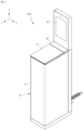
- FIG. 1 is a perspective view of the cup washer 1000 according to an embodiment of the present disclosure viewed from a front upper side.
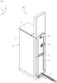
- FIG. 2 is a perspective view of the cup washer 1000 of FIG. 1 viewed from a rear upper side.
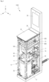
- FIG. 3 is a perspective view of the cup washer 1000 of FIG. 1 in the state in which a front panel 21 is removed.
- the cup washer 1000 may be installed in government offices, companies, or stores.
- the above-mentioned personal cup or reusable cup may mean a cup (made of a glass or plastic material), a mug, a tumbler, or the like.
- the cup washer 1000 may have a tower shape that is long substantially in the vertical direction. Therefore, the floor area required for installation of the cup washer 1000 may be small compared to the total volume of the cup washer 1000.
- the cup washer 1000 may include a frame 10, a panel 20, a display unit 30, a tub 100, a spray unit 300, a water reservoir 50, a sump 60, a circulation pump 70, a drain pump 80, an additive storage part 500, an additive supply part 600, a drying part 400, and a controller 40.
- the controller 40 may integrally control the display unit 30, the circulation pump 70, the drain pump 80, and the additive supply part 600.
- the frame 10 may configure the framework of the cup washer 1000.
- the frame 10 may include a base frame 13, a front frame 11, a rear frame 12, and a horizontal frame 14.
- the base frame 13 may configure the lowermost portion of the cup washer 1000.
- the base frame 13 may be seated on the ground.
- the front frame 11 and the rear frame 12 may define a shape extending upward from the edges of the base frame 13.
- the horizontal frame 14 may interconnect the front frame 11 and the rear frame 12 in the horizontal direction.
- the panel 20 may be coupled to the frame 10 to isolate the components of the cup washer 1000 from the external environment.
- the panel 20 may include a front panel 21, a rear panel 22, a door 25, and a storage unit cover 26.
- the front panel 21 may be coupled to the frame 10 to define the front surface and both side surfaces of the cup washer 1000 under the door 25.
- the rear panel 22 may be coupled to the frame 10 to define the rear surface of the cup washer 1000 below the display unit 30.
- a vent 22a may be provided in the rear panel 22. Outside air may flow into the drying part 400 through the vent 22a.
- An air outlet 22b may be provided in the rear panel 22. Air from the drying part 400 may be discharged to the outside through the air outlet 22b.
- a handle 23 may be provided on the rear panel 22. A manager may easily move the cup washer 1000 by holding the handle 23.
- the display unit 30 may be provided in the upper portion ofthe cup washer 1000.
- the screen of the display unit 30 may face the front side of the cup washer 1000. Therefore, the user of the cup washer 1000 may visually check the screen of the display unit 30 from the front side of the cup washer 1000.
- the display unit 30 may output the operating state ofthe cup washer 1000, such as "wash”, "rinse", and "dry".
- the display unit 30 may be configured with a touch panel. The user may input an operation command for the cup washer 1000 through the display unit 30.
- the user may select a washing mode through the screen of the display unit 30.
- a washing mode may refer to a mode in which a cup C is washed using a detergent and a conditioner.
- the quick washing mode may refer to a mode in which the cup C is washed only by spraying water without a detergent or a conditioner.
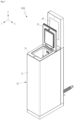
- FIG. 4 is a partial perspective view of the cup washer 1000 of FIG. 1 , illustrating the state in which a door 25 is opened.
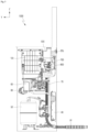
- FIG. 5 is a side view of the cup washer 1000 of FIG. 1 , in which the frame 10, the panel 20, the door 25, and the display unit 30 are not illustrated.
- the panel 20 may include a top panel 24.
- the top panel 24 may be coupled to the upper end portion of the front panel 21.
- the top panel 24 may isolate the components inside the front panel 21 from the external environment at the upper end portion of the front panel 21, except for an upper opening of the tub 100 and an upper opening of the additive storage part 500.
- the storage unit cover 26 may open or close the upper opening of the additive storage part 500.
- the door 25 may open or close the top opening of the tub 100.
- the door 25 may be rotatably coupled to the top panel 24.
- the door 25 When the door 25 is closed (see FIG. 1 ), the door 25 may protrude forward from the front panel 21.
- the user may easily rotate (open) the door 25 by lifting the forward protruding portion upward.
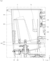
- FIG. 6 is a partial cross-sectional view of the cup washer 1000 of FIG. 5 , illustrating a cup C and a cup lid Ca mounted on the rack 200 with imaginary lines.
- the tub 100 may provide therein a space (hereinafter, referred to as a "washing space") in which the cup C is washed.
- the tub 100 may be in the form of ahollow three-dimensional object with an opening (hereinafter, referred to as a "cup inlet") at approximately the upper end thereof.
- the door 25 can open or close the cup inlet. The user may put the cup C into the washing space or take out the cup C from the washing space through the cup inlet.
- a rack 200 on which the cup C and the cup lid Ca are mounted may be provided in the washing space.
- the rack 200 may be put into or taken out from the washing space through the cup inlet.
- the cup C and the cup lid Ca may be spaced apart from the inner surface of the tub 100 while being mounted on the rack 200.
- the cup C may be placed on the rack 200 with its top and bottom turned upside down.
- the cup washer 1000 may include a spray unit 300.
- the spray unit 300 may be installed in the lower portion of the tub 100. When the cup C is mounted on the rack 200, the upper opening of the cup C may be located above the spray unit 300.
- the spray unit 300 is able to spray water toward the inside and outside of the cup C in the washing space.
- the spray unit 300 may include a first spray nozzle 310 and a second spray nozzle 320.
- FIG. 7 is a schematic view of the cup washer 1000 according to an embodiment of the present disclosure.
- FIG. 7 is a schematic view illustrating the movement paths of water, additive, and air, and the relative arrangement of components may differ from reality.
- the dotted line arrows may indicate the path of water sprayed by the first spray nozzle 310.
- the solid arrows may indicate the path of water sprayed by the second spray nozzle 320.
- the thick black arrow may indicate the movement path of the additive.
- the thick white arrows may refer to air movement paths.
- the water reservoir 50 is able to store water.
- the water reservoir 50 may be heavier than other components.
- the water reservoir 50 may be coupled to the top surface of the base frame 13. Therefore, the overall center of gravity of the cup washer 1000 may be lowered. Therefore, even when the cup washer 1000 is configured in a tower shape that is long substantially in the vertical direction, the possibility of the cup washer 1000 falling over may be reduced.
- the water reservoir 50 may be connected to a water supply pipe. Water from the water supply pipe may be suppliedto the water reservoir 50.
- a water level sensor may be installed in the water reservoir 50.
- An opening/closing valve may be provided between the water supply pipe and the water reservoir 50. The controller 40 can control the opening/closing valve by receiving a signal from the water level sensor.
- a heater and a temperature sensor may be provided in the water reservoir 50.
- the heater may heat the water in the water reservoir 50.
- the controller 40 may control the heater by receiving a signal from the temperature sensor.
- the water in the water reservoir 50 may be supplied into the tub 100 through the washing water supply part 90.
- the washing water supply part 90 may include a washing water supply pipe 91 and an opening/closing valve 92.
- the controller 40 may control the opening/closing valve 92.
- the additive storage part 500 may store an additive therein.
- the additive supply part 600 may supply the additive stored in the additive storage part 500 into the tub 100.
- the user may select a washing mode through the screen of the display unit 30.
- a washing mode through the screen of the display unit 30.
- the user may select a ⁇ normal washing mode" or a ⁇ quick washing mode" through the screen of the display unit 30.
- the normal washing mode may refer to a mode in which a cup C is washed using a detergent and a conditioner.
- the quick washing mode may refer to a mode in which a cup C is washed only by spraying water without a detergent or a conditioner.
- the normal washing mode may include a normal washing step and a drying step.
- the water in the water reservoir 50 may be supplied into the tub 100 through the washing water supply part 90.
- the washing water supply part 90 may include a washing water supply pipe 91 and an opening/closing valve.
- the additive supply part 600 may supply the additive into the tub 100 for a set period of time. The additive may be mixed with water within the tub 100.
- the water mixed with the additive may flow into the sump 60 on the lower side of the tub 100 through the filter part 800 by gravity.
- the circulation pump 70 may press the water flowing into the sump 60 toward the first spray nozzle 310.
- the first spray nozzle 310 may spray the water mixed with the additive toward the inside and outside of the cup C.
- the circulation pump 70 may supply water flowing into the sump 60 into the tub 100 through the washing water spray unit 95.
- the washing water spray unit 95 may spray the water mixed with the additive toward the cup lid Ca.
- the circulation pump 70 may operate for a set period of time. When the set period of time elapses, the water flowing into the sump 60 may move to a drain pipe 81 through the drain pump 80 and may be drained out of the cup washer 1000 (completing of the normal washing step).
- the additive may include a first additive and a second additive.
- the first additive may be provided as a detergent.
- the second additive may be provided as a conditioner.
- the normal washing step may include a first normal washing step and a second normal washing step.
- the first normal washing step may be the step of washing the cup C with the water mixed with the first additive.
- the second normal washing step may be the step of washing the cup C with the water mixed with the second additive.
- the first normal washing step and the second normal washing step may be performed sequentially.
- the drying step may be performed.
- the drying part 400 may supply heated air into the tub 100. During this process, moist air within the tub 100 may be discharged to the outside.
- the drying step may be performed for a set period of time (completing of the drying step).
- the second spray nozzle 320 may be connected to the water supply pipe.
- a three-way valve may be installed between the water supply pipe and the water reservoir 50.
- the second spray nozzle 320 may be connected to the water supply pipe through the three-way valve.
- An opening/closing valve may be provided between the second spray nozzle 320 and the three-way valve.
- the controller 40 may control the three-way valve and the open/close valve.
- the quick washing mode may include a quick washing step and a drying step.
- the second spray nozzle 320 may be connected to the water supply pipe through the three-way valve. In the quick washing mode, the additive may not be supplied into the tub 100.
- the second spray nozzle 320 may spray water not mixed with the additive into the cup C.
- the opening/closing valve may open the flow path between the water supply pipe and the second spray nozzle 320 for a set period of time. When the set period of time elapses, the water flowing into the sump 60 may move to a drain pipe 81 through the drain pump 80 and may be drained out of the cup washer 1000 (completing of the quick washing step).
- the drying step may be performed.
- the drying part 400 may supply heated air into the tub 100. During this process, moist air within the tub 100 may be discharged to the outside.
- the drying step may be performed for a set period of time (completing of the drying step).
- FIG. 8 is a partial perspective view of the cup washer 1000 of FIG. 1 , illustrating the state in which the storage unit cover 26 is opened.
- FIG. 9 is a partial rear view of the cup washer 1000 of FIG. 5 , illustrating the tub 100, the additive storage part 500, and the additive supply part 600.
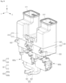
- FIG. 10 is a perspective view illustrating the additive storage part 500 and the additive supply part 600 of FIG. 9 .
- the additive storage part 500 may be provided behind the tub 100.
- the additive storage part 500 may be coupled to the tub 100 by a coupling member such as a bolt.
- Bolt coupling portions 503 where coupling members are coupled to the additive storage part 500 and the tub 100 may be formed.
- the additive storage part 500 may store an additive Ag in an inner portion thereof (hereinafter, referred to as a "storage space 501").
- the additive Ag may include a first additive Ag1 and a second additive Ag2.
- the first additive Ag1 may be provided as a detergent.
- the second additive Ag2 may be provided as a conditioner.
- the additive storage part 500 may include a first additive storage part 510 and a second additive storage part 520.
- the first additive storage part 510 may store the first additive Ag1 inside an inner portion thereof (hereinafter, referred to as a "first storage space 511").
- the first additive storage part 510 may have an opening (hereinafter, referred to as "first additive inlet") at the upper end thereof.
- the user may fill the first additive Ag 1 into the first storage space 511 through the first additive inlet.
- An additive discharge hole 502 may be provided in the lower portion of the first additive storage part 510.
- the second additive storage part 520 may store the second additive Ag2 in the inner portion thereof (hereinafter, referred to as a "second storage space 521").
- the second additive storage part 520 may have an opening (hereinafter, referred to as a "second additive inlet”) at the upper end thereof.
- the user may fill the second additive Ag2 into the second storage space 521 through the second additive inlet.
- An additive discharge hole 502 may be provided in the lower portion of the second additive storage part 520.
- the storage unit cover 26 may simultaneously open or close the first additive inlet and the second additive inlet.
- the top panel 24 may isolate the components inside the front panel 21 from the external environment at the upper end portion of the front panel 21, except for the cup inlet and the additive inlets.
- the edge portion (hereinafter, referred to as a "cover edge portion") of the storage unit cover 26 may be bent downward. In the state in which the cover edge portion seated on the top panel 24, the storage unit cover 26 may simultaneously close the first additive inlet and the second additive inlet.
- the first additive storage part 510 may include a first upper storage unit 512 and a first lower storage unit 513.
- the first upper storage unit 512 may define the upper portion of the first storage space 511.
- the first lower storage unit 513 may define the lower portion of the first storage space 511.
- the lower end portion of the first upper storage unit 512 and the upper end portion of the first lower storage unit 513 may be bonded to each other by adhesive, heat fusion, or the like.
- a floater and a floater sensor may be installed in the first storage space 511.
- the floater may be floated by the first additive Ag 1.
- the floater sensor may detect the height of the floater.
- the controller 40 may receive a signal from the floater sensor.
- the controller 40 may output the amount of the first additive Ag 1 on the screen of the display unit 30.
- the second additive storage part 520 may include a second upper storage unit 522 and a second lower storage unit 523.
- the second upper storage unit 522 may define the upper portion of the second storage space 521.
- the second lower storage unit 523 may define the lower portion of the second storage space 521.
- the lower end portion ofthe second upper storage unit 522 and the upper end portion of the second lower storage unit 523 may be bonded to each other by adhesive, heat fusion, or the like.
- a floater and a floater sensor may be installed in the second storage space 521.
- the floater may be floated by the second additive Ag2.
- the floater sensor may detect the height of the floater.
- the controller 40 may receive a signal from the floater sensor.
- the controller 40 may output the amount of the second additive Ag2 on the screen of the display unit 30.
- the arrow on the X-axis may point to the right based on the user's field of view in front of the cup washer 1000.
- the arrow on the Y axis may point to the front.
- the arrow on the Z axis can point to the top.
- the first additive storage part 510 may be located on one side, and the second additive storage part 520 may be located on the other side.
- the first additive storage part 510 may be located on the left from the rear of the tub 100, and the second additive storage part 520 may be located on the right from the rear of the tub 100.
- the first upper storage unit 512 and the second upper storage unit 522 may be symmetrical with respect to the virtual YZ plane. Therefore, with respect to the X-axis direction, the first additive inlet and the second additive inlet may be spaced apart from each other (see FIG. 8 ).
- the first additive Ag1 may be prevented from flowing into the second storage space 521.
- the first lower storage unit 513 and the second lower storage unit 523 may be manufactured in the same form. Therefore, when manufacturing the first additive storage part 510 and the second additive storage part 520, the first lower storage unit 513 and the second lower storage unit 523 may be manufactured in the same mold. Therefore, the process of manufacturing the additive storage part 500 can be simplified.
- the additive supply part 600 may be provided below the additive storage part 500 behind the tub 100.
- the additive supply part 600 may be coupled to the additive storage part 500 by a coupling member and hook coupling.
- the additive supply part 600 may supply the additive Ag from the storage space 501 into the tub 100.
- the additive Ag may include a first additive Ag 1 and a second additive Ag2.
- the first additive Ag 1 may be provided as a detergent.
- the second additive Ag2 may be provided as a conditioner.
- the additive supply part 600 may include a first additive supply part 600a and a second additive supply part 600b.
- the first additive supply part 600a may be provided below the first additive storage part 510 behind the tub 100.
- the first additive supply part 600a may supply the first additive Ag1 from the first storage space 511 into the tub 100.
- the second additive supply part 600b may be provided below the second additive storage part 520 behind the tub 100.
- the second additive supply part 600b may supply the second additive Ag2 from the second storage space 521 into the tub 100.
- the additive Ag may include a first additive Ag1 and a second additive Ag2.
- the normal washing step may include a first normal washing step and a second normal washing step.
- the first normal washing step may be the step of washing the cup C with the water mixed with the first additive Ag1.
- the second normal washing step may be the step of washing the cup C with the water mixed with the second additive Ag2.
- the controller 40 may individually control the first additive supply part 600a and the second additive supply part 600b. Accordingly, the controller 40 may sequentially perform the first normal washing step and the second normal washing step. That is, after completing the washing of the cup C using the first additive Ag1 (first normal washing step), the controller 40 may perform the washing of the cup C using the second additive Ag2 (second normal washing step).
- the first additive supply part 600a and the second additive supply part 600b may be manufactured in the same form, except for the lengths of the additive transfer pipes 640.
- the first additive supply part 600a and the second additive supply part 600b may be manufactured in the same manufacturing process, and the first additive supply part 600a and the second additive supply part 600b may be separated depending on the assembly locations thereof. Therefore, the manufacturing process of the additive supply part 600 can be simplified.
- the additive supply part 600 should be understood to mean the first additive supply part 600a and the second additive supply part 600b.
- the additive supply part 600 may include an additive pump 610, an additive supply pipe 620, a pump housing 630, and an additive transfer pipe 640.
- the additive supply pipe 620 may include a first additive supply pipe 621 and a second additive supply pipe 622.
- the first additive supply pipe 621 and the second additive supply pipe 622 may be configured as a single supply pipe. That is, the first additive supply pipe 621 and the second additive supply pipe 622 may be manufactured as one piece, and thus the additive supply pipe 620 may have a longitudinally long pipe shape in appearance.
- the first additive supply pipe 621 may form the upper portion of the additive supply pipe 620.
- the first additive supply pipe 621 may take a form of a circular hollow tube that is long substantially in the vertical direction.
- the first additive supply pipe 621 may connect the lower portion of the additive storage part 500 to the inlet 611a of the additive pump 610.
- the first additive supply pipe 621 may provide a passage (hereinafter, referred to as a "first supply passage 621a") through which the additive Ag of the additive storage part 500 moves toward the inlet 611a of the additive pump 610.
- the first supply passage 621a may have a long shape substantially in the vertical direction.
- An inlet insertion portion 621b that is inserted into the inlet 611a of the additive pump 610 may be provided in the lower portion of the first additive supply pipe 621.
- An additive discharge hole 502 into which the first additive supply pipe 621 is inserted in the vertical direction may be provided in the lower portion of the additive storage part 500.
- the inner surface of the additive discharge hole 502 may have a long cylindrical shape in the vertical direction.
- the first additive supply pipe 621 may be inserted into the additive discharge hole 502 by moving upward from the bottom of the additive storage part 500. Therefore, the first additive supply pipe 621 may be coupled to the additive storage part 500.
- a first supply pipe flange 621c may be provided on the outer surface of the first additive supply pipe 621.
- the first supply pipe flange 621c may protrude in the radial direction along the circumferential direction from the outer surface of the first additive supply pipe 621.
- the top surface of the first supply pipe flange 621c may be caught the lower end of the additive discharge hole 502. Therefore, the first additive supply pipe 621 may be inserted into the additive discharge hole 502 at a predetermined depth (height).
- the bottom of the additive storage part 500 may slope downward toward the additive discharge hole 502. Therefore, almost all of the additive Ag filled in the storage space 501 may move toward the additive discharge hole 502 by gravity.
- the upper end of the first additive supply pipe 621 may be somewhat higher than the lowest portion of the storage space 501.
- the opening of the first supply passage 621a may be open not only upward but also to the side.
- the opening of the first supply passage 621a may have substantially the same height as the lowest portion of the storage space 501. Therefore, almost all of the additive Ag filled in the storage space 501 may move to the first supply passage 621aby gravity.
- a pair of sealing members 624 may be interposed between the outer surface of the first additive supply pipe 621 and the inner surface of the additive discharge hole 502.
- the sealing members 624 may be O-rings.
- the pair of sealing members 624 may be spaced apart from each other in the vertical direction within the additive discharge hole 502.
- the upper sealing member 624 may be located in the upper end portion of the additive discharge hole 502.
- the lower sealing member 624 may be located in the lower end portion of the additive discharge hole 502.
- the pair of sealing members 624 may doubly prevent leakage of the additive Ag through the space between the outer surface of the first additive supply pipe 621 and the inner surface of the additive discharge hole 502. Therefore, the leakage of the additive Ag through the space between the outer surface of the first additive supply pipe 621 and the inner surface of the additive discharge hole 502 can be blocked.
- the second additive supply pipe 622 may define the lower portion of the additive supply pipe 620.
- the second additive supply pipe 622 may take a form of a circular hollow tube that is long substantially in the vertical direction.
- the second additive supply pipe 622 may connect the outlet 611b of the additive pump 610 to the additive transfer pipe 640.
- the second additive supply pipe 622 may provide a passage (hereinafter referred to as a "second supply passage 622a") through which the additive Ag discharged from the outlet 611b of the additive pump 610 moves to the outside of the pump housing 630.
- the second supply passage 622a may have along shape substantially in the vertical direction.
- An outlet insertion portion 622b that is inserted into the outlet 611b of the additive pump 610 may be provided at the upper portion ofthe second additive supply pipe 622.
- the first supply passage 621a and the second supply passage 622a may be partitioned by a pipe wall 623.
- the pipe wall 623 may be located between the heights of the inlet 611a and the outlet 611b of the additive pump 610. At this time, the pipe wall 623 may be placed at a height closer to the inlet 611a than the outlet 611b of the additive pump 610. Therefore, almost all ofthe additive Ag flowing from the storage space 501 into the first supply passage 621a may move from the lower end portion of the first supply passage 621a toward the inlet 611a of the additive pump 610.
- the pump housing 630 may accommodate the additive pump 610 therein.
- the pump housing 630 may be placed lower than under the bottom of the storage space 501. Therefore, the additive pump 610 may be placed lower than the bottom of the storage space 501. Therefore, the additive Ag in the storage space 501 may move to the additive pump 610 by gravity.
- the pump housing 630 may include a first accommodation space 631 and a second accommodation space 632 therein.
- the first accommodation space 631 may refer to a space that accommodates the additive pump 610.
- the second accommodation space 632 may refer to a space that accommodates the additive motor 613.
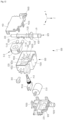
- the pump housing 630 may include a housing body 633, a first housing cover 634, and a second housing cover 635.
- the housing body 633 may include an outer body 633a and an intermediate partition 633b.
- the outer body 633a may define a first accommodation space 631 and a second accommodation space 632 therein together with the first housing cover 634 and the second housing cover 635.
- the first accommodation space 631 and the second accommodation space 632 may be partitioned by the intermediate partition 633b.
- a plurality of protrusions may be formed on the outer body 633a.
- a plurality of protruding locking portions 634a may be provided at an edge of the first housing cover 634.
- the first housing cover 634 may move rearward (in a direction opposite to the direction indicated by the Y-axis arrow) so that the protrusion locking portions 634a can be caught by the body protrusions 633c. Accordingly, the first housing cover 634 can be coupled to the outer body 633a. In this case, the first housing cover 634 may close the first accommodation space 631.
- the protrusion locking portions 634a are spaced apart from the body protrusions 633c, the first housing cover 634 can be separated from the outer body 633a. Therefore, the first housing cover 634 can open the first accommodation space 631.
- the additive supply pipe 620 may be coupled to the pump housing 630 in the first accommodation space 631.
- a first coupling flange 621d may be provided on the outer surface of the first additive supply pipe 621.
- the first coupling flange 621d may protrude in the radial direction along the circumferential direction from the outer surface of the first additive supply pipe 621.
- Partition protrusions 633d which come into close contact with the outer surface of the first additive supply pipe 621, may be provided on the intermediate partition 633b and the first housing cover 634.
- the first additive supply pipe 621 may be coupled to the pump housing 630 by the first coupling flange 621d and the partition protrusions 633d.
- the partition protrusions 633d may provide a vertical movement boundary of the first coupling flange 621d. Therefore, even if external force or vibration is transferred to the pump housing 630, the relative movement between the first additive supply pipe 621 and the pump housing 630 can be blocked. Therefore, the inlet insertion portion 621b can be firmly maintained in the inlet 611a of the additive pump 610 inside the pump housing 630.
- a second coupling flange may be provided on the outer surface of the second additive supply pipe 622.
- the second coupling flange may protrude in the radial direction along the circumferential direction from the outer surface of the second additive supply pipe 622.
- the partition protrusions 633d which come into close contact with the outer surface of the second additive supply pipe 622, may be provided on the intermediate partition 633b.
- the second additive supply pipe 622 may be coupled to the pump housing 630 by the second coupling flange and the partition protrusions 633d.
- the partition protrusions 633d may provide a vertical movement boundary of the second coupling flange. Therefore, even when external force or vibration is transferred to the pump housing 630, the relative movement between the second additive supply pipe 622 and the pump housing 630 can be blocked. Therefore, the outlet insertion portion 622b can be firmly maintained in the outlet 611b of the additive pump 610 inside the pump housing 630.
- the additive pump 610 may be coupled to the pump housing 630 in the first accommodation space 631.
- Close contact ribs 633e which come into close contact with the outer surface of the additive pump 610, may be provided on the intermediate partition 633b and the first housing cover 634.
- the close contact ribs 633e may define a movement boundary of the additive pump 610. Therefore, even when external force or vibration is transferred to the pump housing 630, the relative movement between the additive pump 610 and the pump housing 630 can be blocked. Therefore, the relative movement of the additive supply pipe 620 and the additive pump 610 within the pump housing 630 can be blocked.
- a plurality of protruding locking portions 635a may be provided at an edge of the second housing cover 635.
- the second housing cover 635 may move forward (in the direction indicated by the Y-axis arrow) so that the protrusion locking portions 635a can be caught by the body protrusions 633c. Accordingly, the second housing cover 635 can be coupled to the outer body 633a. At this time, the second housing cover 635 may close the second accommodation space 632.
- the protrusion locking portions 635a are spaced apart from the body protrusions 633c, the second housing cover 635 can be separated from the outer body 633a. Therefore, the second housing cover 635 can open the second accommodation space 632.
- the additive pump 613 and a motor connector 613a may be coupled to the pump housing 630 in the second accommodation space 632.
- the motor connector 613a may be electrically connected to the additive motor 613 by an electric wire.
- a socket may be connected to the motor connector 613a.
- the socket may be connected to the controller 40. Therefore, a signal from the controller 40 and power may be transmitted to the additive motor 613.
- Close contact ribs 633e which come into close contact with the outer surface of the additive motor 613, may be provided on the intermediate partition 633b and the second housing cover 635.
- the close contact ribs 633e may define a movement boundary of the additive pump 613. Therefore, even when external force or vibration is transferred to the pump housing 630, the relative movement between the additive motor 613 and the pump housing 630 can be blocked. Therefore, the relative movement of the additive motor 613 inside the pump housing 630 can be blocked.
- the first housing cover 634 may be coupled to the lower portion of the additive storage part 500.
- a first cover fastening portion 634b may be provided on the first housing cover 634, and a first storage unit fastening portion 504 may be provided on the lower portion of the additive storage portion 500.
- the first cover fastening portion 634b may be coupled to the first storage unit fastening portion 504.
- the first cover fastening portion 634b and the first storage unit fastening portion 504 may be detachably coupled to each other with a quick release buckle structure.
- the second housing cover 635 may be coupled to the lower portion of the additive storage part 500.
- a second cover fastening portion 635b may be provided on the second housing cover 635, and a second storage unit fastening portion 505 may be provided on the lower portion of the additive storage part 500.
- the second cover fastening portion 635b may be coupled to the second storage unit fastening portion 505.
- the second cover fastening portion 635b and the second storage unit fastening portion 505 may be detachably coupled to each other with a bolt fastening structure.
- the first housing cover 634 and the second housing cover 635 may be coupled to the lower portion of the additive storage part 500 from opposite sides with respect to the first additive supply pipe 621. Therefore, even when external force or vibration is transferred to the pump housing 630, the relative movement between the additive storage part 500 and the pump housing 630 can be blocked on both sides with the first additive supply pipe 621 interposed therebetween. Therefore, the state in which the first additive supply pipe 621 is coupled to the additive storage part 500 can be firmly maintained. Therefore, the leakage of the additive Ag through the space between the outer surface of the first additive supply pipe 621 and the inner surface of the additive discharge hole 502 can be blocked.
- the additive pump 610 may press the additive Ag introduced into the first supply passage 621a toward the second supply passage 622a.
- the additive pump 610 may be disposed below the additive storage part 500. Therefore, the additive Ag in the storage space 501 may move to the additive pump 610 by gravity.
- the additive pump 610 may include an additive tube 611, a pump cover 617, a rotating roller 612, an additive motor 613, and a power shaft 614.
- the additive tube 611 is made of a tube made of an elastically deformable material.
- the additive tube 611 may include an inlet 611a and an outlet 611b.
- the additive tube 611 may be bent between the inlet 611a and the outlet 61 1b.
- the additive tube 611 may be bent substantially in a " ⁇ " shape of between the inlet 611a and the outlet 611b.
- the additive tube 611 may provide a passage (hereinafter, referred to as a "flexible passage") through which the additive Ag flowing into the inlet 61 1a moves to the outlet 611b.
- the inlet 611a of the additive tube 611 may be connected to the first supply passage 621a.
- the outlet 611b may be connected to the second supply passage 622a.
- An inlet insertion portion 621b may be provided in the lower portion of the first additive supply pipe 621.
- the inlet insertion portion 621b may have a circular tube shape.
- the inlet insertion portion 621b may be inserted into the inlet 611a of the additive tube 611.
- the inlet insertion portion 621b may connect the first supply passage 621a to the flexible passage.
- the outer diameter of the inlet insertion portion 621b may be larger than the inner diameter of the inlet 611a. Therefore, while the inlet 611a is elastically deformed, the inlet insertion portion 621b may be forcibly inserted into the inlet 611a of the additive tube 611.
- a protrusion may be provided on the outer surface of the inlet insertion portion 621b. The protrusion may protrude radially along the circumferential direction. Therefore, the amount of elastic deformation of the inlet 611a may increase at the protrusion. Therefore, the inlet insertion portion 621b can be firmly maintained in the inlet 611a of the additive pump 610 inside the pump housing 630.
- An outlet insertion portion 622b may be provided on the upper portion of the second additive supply pipe 622.
- the outlet insertion portion 622b may have a circular tube shape.
- the outlet insertion portion 622b may be inserted into the outlet 611b of the additive tube 611.
- the outlet insertion portion 622b may connect the second supply passage 622a to the flexible passage.
- the outer diameter of the outlet insertion portion 622b may be larger than the inner diameter of the outlet 611b. Therefore, while the outlet 611b is elastically deformed, the outlet insertion portion 622b may be forcibly inserted into the outlet 611b of the additive tube 611.
- a protrusion may be provided on the outer surface of the outlet insertion portion 622b. The protrusion may protrude radially along the circumferential direction. Therefore, the amount of elastic deformation of the outlet 611b may increase at the protrusion. Therefore, the outlet insertion portion 622b can be firmly maintained in the outlet 611b of the additive pump 610 inside the pump housing 630.
- the first additive supply pipe 621 and the second additive supply pipe 622 may be manufactured as one piece to have a circular hollow tube shape that is long substantially in the vertical direction. Therefore, the arrangement of the additive tube 611 can be optimized by placing the additive tube 611 on one side of the additive supply pipe 620.
- the additive tube 611 may be placed in the direction indicated by the X-axis arrow.
- the additive pump 610 and pump housing 630 can be efficiently placed in the space below the additive storage part 500 by providing the additive discharge hole 502 on a relatively left side (opposite to the direction indicated by the X-axis arrow) in the lower portion of the first additive storage part 510 with respect to the X-axis.
- the first additive supply pipe 621 and the inlet 611a may be connected at a predetermined angle.
- the inlet insertion portion 621b may protrude from the lower portion of the first additive supply pipe 621 in the direction of the X-axis arrow, and the first additive supply pipe 621 and the inlet 611a may be connected at an angle of about 90 degrees.
- the second additive supply pipe 622 and the outlet 611b may be connected at a predetermined angle.
- the outlet insertion portion 622b may protrude from the upper portion of the second additive supply pipe 622 in the direction of the X-axis arrow, and the second additive supply pipe 622 and the outlet 611b may be connected at an angle of about 90 degrees.
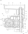
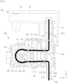
- FIG. 14 is a cross-sectional view taken along line A-A' of FIG. 11 , illustrating the flow of an additive.
- the additive tube 611 may be divided into an inflow section Ts1, a pressing section Ts2, and a discharge section Ts3 along the longitudinal direction.
- the pressing section Ts2 may be a section in which the rotating roller 612 presses the additive Ag toward the outlet 611b.
- the inflow section Ts1 may be a section in which the additive Ag flowing into the inlet 611a moves toward the pressing section Ts2.
- the discharge section Ts3 may be a section in which the additive Ag that has passed the pressing section Ts2 moves toward the outlet 611b.
- the pump cover 617 may accommodate the pressing section Ts2 of the additive tube 611 therein.
- the pressing section Ts2 of the additive tube 611 may be arranged along the circumferential direction around the roller central shaft 621a inside the pump cover 617.
- the inner surface of the pump cover 617 may come into contact with the pressing section Ts2 of the additive tube 611 on the opposite side to the roller central shaft 621a.
- a radially expanded portion (hereinafter, referred to as a "tube expansion portion”) may be provided on the outer surface of the additive tube 611 in the inflow section Ts1 and the discharge section Ts3.
- the tube expansion portion may be inserted and coupled to the pump cover 617. Accordingly, the pressing section Ts2 of the additive tube 611 can be maintained in the state of being arranged along the circumferential direction around the roller central shaft 621a.
- the pump cover 617 may accommodate the rotating roller 612 and the pressing section Ts2 of the additive tube 611 therein.
- the pressing section Ts2 of the additive tube 611 may be disposed in the rotating path of the rotating roller 612. Therefore, the rotating roller 612 may pressing the pressing section Ts2 of the additive tube 611 while being rotated by the additive motor 613. With reference to FIG. 14 , the rotating roller 612 may press the pressing section TS2 of the additive tube 611 while rotating counterclockwise. Therefore, the additive Ag in the flexible passage can move from the pressing section Ts2 to the discharge section Ts3. In this case, the additive Ag in the flexible passage can move from the inflow section Ts1 to the pressing section Ts2.
- the torque of the additive motor 613 may be transferred to the central shaft of the rotating roller 612 (hereinafter, referred to as a "roller central shaft 621a") by the power shaft 614.
- the roller central shaft 621a may be rotatably coupled to the pump cover 617.
- the additive tube 611 may be placed in the direction indicated by the X-axis arrow, and the roller center shaft 621a and the power shaft 614 may be arranged parallel to the Y-axis direction.
- the power shaft 614 may be provided between the heights of the inlet 611a and the outlet 611b. Therefore, the inflow section Ts1, the pressing section Ts2, and the discharge section Ts3 of the additive tube 611 may be arranged between the heights of the inlet 611a and the outlet 611b.
- the inflow section Ts1 may be connected to the first additive supply pipe 621 at substantially the shortest distance.
- the inflow section Ts 1 may be arranged substantially parallel to the X-axis. Therefore, almost all of the additive Ag in the inflow section Ts1 can move to the pressing section Ts2 by gravity without remaining in the inflow section Ts1.
- the discharge section Ts3 may be connected to the second additive supply pipe 622 at substantially the shortest distance.
- the discharge section Ts3 may be arranged substantially parallel to the X-axis. Therefore, almost all of the additive Ag in the discharge section Ts3 can move to the second supply passage 622a by gravity without remaining in the discharge section Ts3.
- the additive pump 610 may be coupled to the pump housing 630 in the first accommodation space 631.
- the additive motor 613 may be coupled to the pump housing 630 in the second accommodation space 632.
- the power shaft 614 may pass through the intermediate partition 633b and may be coupled to the roller central shaft 621a.
- the power shaft 614 may be rotatably coupled to the intermediate partition 633b and/or the second housing cover 635.
- the shaft of the additive motor 613 (hereinafter, referred to as a ⁇ motor shaft") and the power shaft 614 may be connected to each other by a gear.
- the power shaft 614 may be arranged parallel to the Y-axis direction, and the motor shaft may be arranged parallel to the X-axis direction.
- the motor shaft and power shaft 614 may be connected to each other by a worm and a worm gear.
- the worm may be provided on the motor shaft, and the worm gear may be provided on the power shaft 614.
- the rotating rollers 612 may be spaced apart from the roller central shaft 621a in the radial direction, and the rotating shaft of each rotating roller 612 (hereinafter, referred to as a "roller shaft 612b") may be coupled to the roller central shaft 621a Therefore, the rotating rollers 612 can rotate along the circumferential direction around the roller central shaft 621a
- three rotating rollers 612 may be provided, and the rotating rollers 612 may form an angle of 120 degrees with each other around the roller central shaft 621a
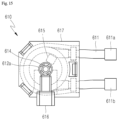
- FIG. 15 is a view illustrating the magnetic member 615 and the magnetic force detector 616 of the additive pump 610 of FIG. 12 .
- the additive pump 610 may include a magnetic force member 615 and a magnetic force detector 616.
- the magnetic member 615 may be provided with a permanent magnet.
- the magnetic member 615 may be spaced apart from the roller central shaft 621a in the radial direction and may be coupled to the roller central shaft 621a. Therefore, the magnetic member 615 can rotate along the circumferential direction around the roller central shaft 621a together with the rotating roller 612 by the additive motor 613.
- the magnetic force detector 616 may detect the magnetic force member 615.
- a detector insertion portion may be provided in the housing body 633.
- the magnetic force detector 616 may be inserted into the detector insertion portion.
- the magnetic force detector 616 may be provided on one side of the rotation path of the magnetic member 615 centered on the roller central shaft 621a while being inserted into the detector insertion portion.
- the magnetic force detector 616 may be configured with a Hall sensor.
- the magnetic force detector 616 may detect the magnetic force member 615 on one side of the rotation path of the magnetic force member 615 centered on the roller central shaft 621a.
- the magnetic force detector 616 may be connected to the controller 40. Therefore, the controller 40 may detect the rotation of the rotating roller 612 by the magnetic force detector 616.
- the controller 40 may control the input amount of the additive Ag by a signal from the magnetic force detector 616. For example, the controller 40 may stop the additive motor 613 when receiving a signal from the magnetic force detector 616 N times after rotating the additive motor 613. Therefore, the controller 40 can precisely control the amount of additive Ag supplied into the tub 100.
- FIG. 16 is a view of a washing space inside the tub 10 of FIG. 6 viewed from a front upper side.
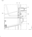
- FIG. 17 is a partial enlarged view of FIG. 6 , illustrating a washing water inflow pipe and an additive transfer pipe 640.
- the additive transfer pipe 640 may connect the second additive supply pipe 622 to the tub 100.
- the additive transfer pipe 640 may be connected to the tub 100 below the outlet 611b. Therefore, the additive transfer pipe 640 can supply the additive Ag into the tub 100 from below the outlet 611b. Therefore, almost all of the additive Ag discharged from the additive pump 610 to the second supply passage 622a can move into the tub 100 by gravity.
- the additive transfer pipe 640 may be connected to the additive inlet 103 on the inner wall of the tub 100. That is, the additive supply part 600 may supply the additive Ag into the tub 100 through the additive inlet 103.
- the washing water supply part 90 may supply water to a specific region (hereinafter, referred to as a "first region 104") on the inner wall of the tub 100.
- the additive inlet 103 may be provided in the first region 104 of the inner wall of the tub 100.
- the first region 104 may be located between the first additive supply part 600a and the second additive supply part 600b with respect to the X-axis.
- the additive transfer pipe 640 may include a first additive transfer pipe 641 and a second additive transfer pipe 642 (see FIG. 9 ).
- the first additive transfer pipe 641 may connect the second additive supply pipe 622 of the first additive supply part 600a to the tub 100.
- the first additive transfer pipe 641 may be connected to the tub 100 below the outlet 611b. Therefore, the first additive transfer pipe 641 can supply the first additive Ag1 into the tub 100 from below the outlet 611b. Accordingly, almost all of the additive Ag discharged from the additive pump 610 of the first additive supply part 600a to the second supply passage 622a can move into the tub 100 by gravity.
- the first additive transfer pipe 641 may be connected to the first additive inlet 103a on the inner wall of the tub 100. That is, the first additive supply part 600a may supply the first additive Ag1 into the tub 100 through the first additive inlet 103a.
- the first additive inlet 103a may be provided in the first region 104 of the inner wall of the tub 100.
- the second additive transfer pipe 642 may connect the second additive supply pipe 622 of the second additive supply part 600b to the tub 100.
- the second additive transfer pipe 642 may be connected to the tub 100 below the outlet 611b. Therefore, the second additive transfer pipe 642 can supply the second additive Ag2 into the tub 100 from below the outlet 611b. Accordingly, almost all of the additive Ag discharged from the additive pump 610 of the second additive supply part 600a to the second supply passage 622a can move into the tub 100 by gravity.
- the second additive transfer pipe 642 may be connected to the second additive inlet 103a on the inner wall of the tub 100. That is, the second additive supply part 600b may supply the second additive Ag2 into the tub 100 through the second additive inlet 103b.
- the second additive inlet 103b may be provided in the first region 104 of the inner wall of the tub 100.
- the first region 104 may be located between the first additive supply part 600a and the second additive supply part 600b with respect to the X-axis.
- the first additive Ag1 may be provided as a detergent.
- the second additive Ag2 may be provided as a conditioner. When washing the cup C, a smaller amount of the conditioner than the detergent (about 0.2 times the amount of the detergent) may be required.
- the second additive transfer pipe 642 may have a shorter length than the first additive transfer pipe 641. Therefore, even when the second additive Ag2 is supplied in a smaller amount than the first additive Ag1, almost all of the second additive Ag2 can move into the tub 100 rather than remaining inside the second additive transfer pipe 642.
- the washing water supply part 90 may include a washing water supply pipe 91 and an opening/closing valve 92.
- the controller 40 may control the opening/closing valve 92.
- the washing water supply pipe 91 may be connected to a washing water inlet 102 on the inner wall of the tub 100.
- the washing water inlet 102 may be located above the additive inlet 103 within the first region 104.
- the water discharged from the washing water inlet 102 may fall toward the additive inlet 103 by gravity. Accordingly, the washing water supply part 90 can supply water to the first region 104.
- the first additive inlet 103a and the second additive inlet 103b may be spaced apart from each other in the horizontal direction within the first region 104. With respect to the X-axis, the first additive inlet 103a and the second additive inlet 103b may be spaced apart from the washing water inlet 102 at equal intervals in the horizontal direction. Accordingly, the first additive Ag1 discharged from the first additive inlet 103a into the tub 100 may be mixed with the water discharged from the washing water inlet 102. In addition, the first additive Ag2 discharged from the second additive inlet 103b into the tub 100 may be mixed with the water discharged from the washing water inlet 102.
- a mixing guide 270 may be provided in front of the first region 104 in the washing space.
- the mixing guide 270 may be detachably coupled to the rack 200.
- the mixing guide 270 may guide the water flowing into the tub 100 through the washing water inlet 102 toward the additive inlet 103.
- the mixing guide 270 may define a space (hereinafter, referred to as a "mixing space 270a") in which water is mixed with the additive Ag while moving between the first region 104 and the mixing guide 270.
- the mixing space 270a may be provided in front of the first region 104.
- a gap may be provided between the mixing guide 270 and the inner wall of the tub 100 below the mixing guide 270. Therefore, the water discharged from the washing water inlet 102 may pass through the first region 104 and may fall from the lower portion of the mixing guide 270 into the tub 100. The water discharged from the washing water inlet 102 may form a constant flow rate in the mixing space 270a. Therefore, the additive Ag discharged into the tub 100 from the additive inlet 103 can be quickly mixed with the water discharged from the washing water inlet 102 in the mixing space 270a.
Landscapes
- Engineering & Computer Science (AREA)
- Mechanical Engineering (AREA)
- General Engineering & Computer Science (AREA)
- Washing And Drying Of Tableware (AREA)
- Detail Structures Of Washing Machines And Dryers (AREA)
Abstract
Disclosed is a cup washer. The cup washer (1000) of the present disclosure includes an additive storage part (500) and an additive supply part (600). The additive storage part (500) is configured to store an additive in a storage space (501). The additive supply part (600) is configured to supply the additive into the tub (100). The additive supply part (600) includes an additive pump (610) and a first additive supply pipe (621). The additive pump (610) is located below the additive storage part (500). The first additive supply pipe (621) connects the lower portion of the additive storage part (500) to the inlet (611a) of the additive pump (610). The first additive supply pipe (621) is configured to provide a first supply passage (621a) through which the additive of the additive storage part (500) moves toward the inlet (611a) of the additive pump (610). The first additive supply pipe (621) and the inlet (611a) are connected to each other at a predetermined angle.
Description
- This application is based on and claims priority under 35 U.S.C. 119 to
Korean Patent Application No. 10-2023-0180144, filed on December 12, 2023 - The present disclosure relates to a cup washer, and more specifically, to a cup washer that washes a cup by spraying water.
- A cup washer is a device that washes a cup by spraying water. Recently, as the awareness of practicing carbon neutrality has expanded throughout society, the number of people carrying personal or reusable cups has increased. Accordingly, the number of government offices, companies, and stores where cup washers are installed for the hygiene and convenience of users (employees) is increasing.
-
Korean Patent No. 2114048 - According to Prior Art Document 1, since the detergent is supplied to the supply pipe only by opening the third valve by a controller, there is a limitation in precisely controlling the amount of detergent supplied to the supply pipe.
- Regarding detergent input technology, International Patent Publication No.
WO2023/274943 (hereinafter, referred to as "Prior Document 2") discloses a "dishwasher detergent dispenser". The dishwasher detergent dispenser is installed in a dishwasher. - An internal washing chamber in the dishwasher is opened and closed by a door. The detergent dispenser is installed on the inner wall of the door. The detergent dispenser includes a housing compartment, a supply container, and a delivery mechanism (a pump unit or a pump driver). The pump driver and the housing compartment are first coupled to the inner wall of the door, and then the supply container is coupled to the housing compartment. At this time, the pump unit is coupled between the supply vessel and the housing compartment. The supply container defines a space inside which the detergent is filled (hereinafter, referred to as a "filling space").
- The pump driver includes an electric motor and a drive shaft. The pump unit includes a flexible tube, a rotor, and a plurality of pump elements (a plurality of rollers). When the electric motor rotates, the pump elements connected to the drive shaft rotate to pressurize the flexible tube, and the detergent in the flexible tube flows out into the washing chamber.
- According to Prior Art Document 2, the inlet and outlet of the pump unit are located below the drive shaft, and the upper portion of the flexible tube is higher than the lower portion of the filling space. Therefore, the detergent in the filling space rises along the flexible tube, then falls, and then flows out into the washing chamber. Therefore, when the height of the detergent in the filling space is lower than the upper portion of the flexible tube, all of the detergent in the filling space may not flow out into the washing chamber through the flexible tube, and the remaining amount may remain in the filling space and the lower portion of the flexible tube.
- According to Prior Art Document 2, the pump driver, the housing compartment, the pump unit, and the supply container are sequentially assembled to the inner wall of the door. Therefore, to repair or replace the pump driver, it is necessary to remove all of the housing compartment, the pump unit, and the supply container from the inner wall of the door. Therefore, it takes a long time to maintain the pump driver. Additionally, when the pump unit is separated during this process, there is a possibility that some of the detergent may leak out from the inlet and outlet of the pump unit.
- The amount of detergent that flows out into the washing chamber through a flexible tube is generally proportional to the rotation amount of a pump element (roller). However, according to Prior Art Document 2, the amount of detergent flowing into the washing chamber is controlled by controlling the operation (time) of the electric motor. Therefore, there are limitations in precisely controlling the amount of the detergent flowing into the washing chamber.
- The present disclosure is to solve the above-described problems of a cup washer that washes a cup by spraying water.
- Specifically, the present disclosure is to provide a cup washer in which an additive storage and input structure is optimized such that the entire additive stored therein can be introduced into a pump and the entire additive discharged by the pump can be put into a tub.
- In addition, the present disclosure is to provide a cup washer in which a pump assembly structure is simplified and optimized so that the pump can be more easily and efficiently maintained and managed.
- Furthermore, the present disclosure is to provide a cup washer in which the amount of pressurization of a tube can be correctly monitored and the amount of the additive to be put into the tub can be precisely controlled.
- The technical problems to be addressed by the present disclosure are not limited to those described above, and other technical problems, which are not described above, will be clearly understood by a person ordinarily skilled in the related art to which the present disclosure belongs.
- The present application discloses a cup washer that washes cups by spraying water into a tub, wherein the cup washer may include an additive storage part and an additive supply part.
- The additive storage part may store an additive in the storage space.
- The additive supply part may supply the additive into a tub.
- The additive supply part may include an additive pump and a first additive supply pipe.
- The additive pump may be placed below the additive storage part.
- The first additive supply pipe may connect the lower portion of the additive storage part to the inlet to provide a first supply passage through which the additive of the additive storage part moves toward the inlet of the additive pump.
- The first additive supply pipe and the inlet may be connected at a predetermined angle.
- The additive supply part may include a pump housing.
- The pump housing is located lower than the bottom of the storage space and may accommodate an additive pump therein.
- The first additive supply pipe may be coupled to the additive storage part and the pump housing.
- An additive discharge hole into which the first additive supply pipe is vertically inserted may be provided in the lower portion of the additive storage part.
- A pair of sealing members may be interposed between the outer surface of the first additive supply pipe and the inner surface of the additive discharge hole, wherein the pair of sealing members may be vertically spaced apart from each other within the additive discharge hole.
- The additive supply part may include a second additive supply pipe.
- The second additive supply pipe may be connected to the outlet to provide a second supply passage through which the additive discharged from the outlet of the additive pump located below the inlet moves to the outside of the pump housing.
- The second additive supply pipe and the outlet may be connected at a predetermined angle.
- The first additive supply pipe and the second additive supply pipe may be configured as a single supply pipe.
- Alternatively, the first additive supply pipe and the second additive supply pipe may be configured as separate supply pipes. The first additive supply pipe and the second additive supply pipe may be manufactured separately and coupled in the form of a longitudinally long pipe in appearance.
- The first supply passage and the second supply passage may be partitioned by a pipe wall located between the heights of the inlet and outlet.
- The pipe wall may be placed at a height closer to the inlet than the outlet.
- The additive pump may include an additive tube and a rotating roller.
- The additive tube may include an inlet and an outlet.
- The rotating roller may be rotated by the additive motor to pressurize the additive tube.
- A power shaft configured to transmit the torque of the additive motor to the rotating roller may be provided between the heights of the inlet and the outlet.
- The additive tube may have a shape bent between the inlet and the outlet.
- The pump housing may include a housing body, a first housing cover, and a second housing cover.
- The housing body may include an intermediate partition through which the power shaft passes, and the intermediate partition may partition a first accommodation space configured to accommodate the additive pump and a second accommodation space configured to accommodate the additive motor.
- The first housing cover may be configured to open and close the first accommodation space.
- The second housing cover may be configured to open and close the second accommodation space.
- The first housing cover and the second housing cover may be coupled to the lower portion of the additive storage part from opposite sides with respect to the first additive supply pipe.
- The additive pump may include a magnetic force member and a magnetic force detector.
- The magnetic member may be configured to be rotated by the additive motor.
- The magnetic force detector may be provided on one side of the rotation path of the magnetic force member to detect the rotation of the rotating roller.
- The amount of the additive added may be controlled by a signal from the magnetic force detector.
- The first additive supply pipe and the inlet may be connected at an angle of 90 degrees.
- The second additive supply pipe and the outlet may be connected at an angle of 90 degrees.
- The second additive supply pipe may be coupled with the pump housing.
- The additive supply part may include an additive transfer pipe.
- The additive transfer pipe may connect the second additive supply pipe to the tub to supply the additive into the tub from below the outlet.
- The additive supply part may supply the additive into the tub through an additive inlet provided in the first region of the inner wall of the tub.
- The cup washer described herein may include a washing water supply part configured to supply water to the first region.
- The additive storage part may include a first additive storage part and a second additive storage part.
- The first additive storage part may store a first additive in a first storage space.
- The second additive storage part may store a second additive in a second storage space.
- The additive supply part may include a first additive supply part and a second additive supply part.
- The first additive supply part may supply the first additive into the tub.
- The second additive supply part may supply the second additive into the tub.
- The cup washer described herein may include a controller configured to individually control the first additive supply part and the second additive supply part.
- The first additive supply part may be configured to supply the first additive into the tub through a first additive inlet formed in the first region of the inner wall of the tub.
- The second additive supply part may be configured to supply the second additive into the tub through the second additive inlet formed in the first region.
- With the cup washer according to an embodiment of the present disclosure, the first additive supply pipe connects the lower portion of the additive storage part to the inlet of the additive pump so that the first supply passage through which the additive of the additive storage part moves toward the inlet of the additive pump can be provided. At this time, the first additive supply pipe and the inlet may be connected at a predetermined angle. Therefore, by placing the additive tube on one side of the additive supply pipe, the additive pump and the pump housing can be efficiently placed in the space below the additive storage part.
- With the cup washer according to an embodiment of the present disclosure, the second additive supply pipe may be connected to the outlet of the additive pump. The second additive supply pipe may provide a second supply passage through which the additive discharged from the outlet of the additive pump located below the inlet moves to the outside of the pump housing. In this case, the second additive supply pipe and the outlet of the additive pump may be connected at a predetermined angle. Therefore, by placing the additive tube on one side of the additive supply pipe, the additive pump and the pump housing can be efficiently placed in the space below the additive storage part.
- With the cup washer according to an embodiment of the present disclosure, the pump housing may accommodate the additive pump therein. The pump housing may be placed lower than the bottom of the storage space. Therefore, the additive pump can be placed lower than the bottom of the storage space. Therefore, the additive in the storage space can move to the additive pump by gravity.
- With the cup washer according to an embodiment of the present disclosure, the power shaft configured to transmit the torque of the additive motor to the rotating roller may be provided between the heights of the inlet and the outlet. Therefore, the additive tube can be placed between the height of the inlet and outlet. In addition, the additive tube may be connected to the first additive supply pipe at approximately the shortest distance. Therefore, almost all of the additives in an inflow section can be moved to a pressing section by gravity without remaining in the inflow section. In addition, the additive tube may be connected to the second additive supply pipe at approximately the shortest distance. Therefore, almost all of the additives in a discharge section can be moved to the second supply passage by gravity without remaining in the discharge section.
- With the cup washer according to an embodiment of the present disclosure, the first additive supply pipe and the second additive supply pipe may be configured as a single supply pipe, and the first supply passage and the second supply passage may be partitioned by the pipe wall. The pipe wall may be located between the heights of the inlet and outlet of the additive pump. In this case, the pipe wall may be placed at a height closer to the inlet than the outlet of the additive pump. Therefore, almost all of the additives introduced into the first supply passage from the storage space can move from the lower end portion of the first supply passage toward the inlet of the additive pump.
- With the cup washer according to an embodiment of the present disclosure, a pair of sealing members may be interposed between the outer surface of the first additive supply pipe and the inner surface of the additive discharge hole. The pair of sealing members may be vertically spaced apart from each other within the additive discharge hole. The pair of sealing members may doubly prevent additive leakage through a space between the outer surface of the first additive supply pipe and the inner surface of the additive discharge hole. Therefore, leakage of the additive through the space between the outer surface of the first additive supply pipe and the inner surface of the additive discharge hole can be blocked.
- With the cup washer according to an embodiment of the present disclosure, the pump housing may configure a first accommodation space and a second accommodation space therein. The first accommodation space may accommodate the additive pump. The second accommodation space may accommodate the additive motor. The first accommodation space and the second accommodation space may be partitioned by an intermediate partition. The first housing cover may be configured to open and close the first accommodation space. The second housing cover may be configured to open and close the second accommodation space. Therefore, the additive pump can be easily maintained and repaired by opening the first housing cover. In addition, the additive motor can be easily maintained and repaired by opening the second housing cover.
- With the cup washer according to an embodiment of the present disclosure, close contact ribs, which are in close contact with the outer surface of the additive pump may be provided on the intermediate partition and the first housing cover. In the state in which the close contact ribs are in close contact with the outer surface of the additive pump in the first accommodation space, the close contact ribs may provide a movement boundary of the additive pump. Therefore, even when external force or vibration is transferred to the pump housing, the relative movement between the additive pump and the pump housing can be blocked. Therefore, the relative movement between the additive supply pipe and the additive pump can be blocked inside the pump housing.
- With the cup washer according to an embodiment of the present disclosure, close contact ribs that are in close contact with the outer surface of the additive motor may be provided on the intermediate partition and the second housing cover. In the state in which the close contact ribs are in close contact with the outer surface of the additive motor in the second accommodation space, the close contact ribs may form a movement boundary of the additive motor. Therefore, even when external force or vibration is transferred to the pump housing, the relative movement between the additive motor and the pump housing may be blocked. Therefore, the relative movement between the additive motor inside the pump housing can be blocked.
- With the cup washer according to an embodiment of the present disclosure, the first housing cover and the second housing cover may be coupled to the lower portion of the additive storage part from opposite sides with respect to the first additive supply pipe. Therefore, even when external force or vibration is transferred to the pump housing, the relative movement between the additive storage part and the pump housing can be blocked on the opposite sides with the first additive supply pipe interposed therebetween. Therefore, the state in which the first additive supply pipe is coupled to the additive storage part can be firmly maintained. Therefore, leakage of the additive through the space between the outer surface of the first additive supply pipe and the inner surface of the additive discharge hole can be blocked.
- With the cup washer according to an embodiment of the present disclosure, the additive pump may include a magnetic force member and a magnetic force detector. The magnetic force detector may be configured to detector the magnetic force member on one side of the rotation path of the magnetic force member centered around the roller central shaft. Therefore, the controller may detect the rotation of the rotating roller with the magnetic force detector. Therefore, the controller can precisely control the amount of the additive supplied into the tub.
- With the cup washer according to an embodiment of the present disclosure, the additive transfer pipe may connect the second additive supply pipe to the tub. The additive transfer pipe may be connected to the tub below the outlet. Therefore, the additive transfer pipe can supply the additive into the tub from below the outlet. Therefore, almost all of the additive discharged from the additive pump to the second supply passage can move into the tub by gravity.
- According to the cup washer according to an embodiment of the present disclosure, the second additive transfer pipe may have a shorter length than the first additive transfer pipe. Therefore, even when the second additive is supplied in a smaller amount than the first additive, almost all of the second additive can move into the tub rather than remaining inside the second additive transfer pipe.
- According to the cup washer according to an embodiment of the present disclosure, the first lower storage unit and the second lower storage unit may be manufactured in the same form. Therefore, when manufacturing the first additive storage part and the second additive storage part, the first lower storage unit and the second lower storage unit can be manufactured in the same mold. Therefore, the process of manufacturing the additive storage part can be simplified.
- With the cup washer according to an embodiment of the present disclosure, the first additive supply part and the second additive supply part may be manufactured in the same form, except for the lengths of the additive transfer pipes. When manufacturing the cup washer, the first additive supply part and the second additive supply part may be manufactured in the same manufacturing process, and may be divided into the first additive supply part and a second additive supply part depending on an assembly location. Therefore, the manufacturing process of the additive supply part can be simplified.
- The above and other aspects, features, and advantages of the present disclosure will be more apparent from the following detailed description taken in conjunction with the accompanying drawings, in which:
-
FIG. 1 is a perspective view of the cup washer according to an embodiment of the present disclosure viewed from a front upper side; -
FIG. 2 is a perspective view of the cup washer ofFIG. 1 viewed from a rear upper side; - FIG. is a perspective view of the cup washer of
FIG. 1 in the state in which a front panel is removed; -
FIG. 4 is a partial perspective view of the cup washer ofFIG. 1 , illustrating the state in which a door is opened; -
FIG. 5 is a side view of the cup washer ofFIG. 1 in which a frame, a panel, a door, and a display unit are not illustrated; -
FIG. 6 is a partial cross-sectional view of the cup washer ofFIG. 5 in which a cup and a cup lid mounted on a rack are illustrated with imaginary lines; -
FIG. 7 is a schematic view of a cup washer according to an embodiment of the present disclosure; -
FIG. 8 is a partial perspective view of the cup washer ofFIG. 1 , illustrating the state in which a storage unit cover is opened; -
FIG. 9 is a partial rear view of the cup washer ofFIG. 5 , illustrating a tub, an additive storage part, and an additive supply part; -
FIG. 10 is a perspective view illustrating the additive storage part and the additive supply part ofFIG. 9 ; -
FIG. 11 is a side view illustrating the additive storage part and the additive supply part ofFIG. 10 ; -
FIG. 12 is an exploded perspective view of the additive supply part ofFIG. 10 ; -
FIG. 13 is a cross-sectional view taken along line A-A' inFIG. 11 ; -
FIG. 14 is a cross-sectional view taken along line A-A' ofFIG. 11 , illustrating the flow of an additive; -
FIG. 15 is a view illustrating a magnetic force member and a magnetic force detector of the additive pump ofFIG. 12 ; -
FIG. 16 is a view of a washing space inside the tub ofFIG. 6 viewed from a front upper side; and -
FIG. 17 is a partial enlarged view ofFIG. 6 , illustrating a washing water inflow pipe and an additive transfer pipe. - Hereinafter, embodiments of the present disclosure will be described in detail with reference to the accompanying drawings. However, in the following description of the present disclosure, descriptions of already well-known functions or constructions will be omitted in order to make the gist of the present disclosure clear.
- The X direction, Y direction, and Z direction to be described in embodiments of the present disclosure may be orthogonal to each other. Each of the X and Y directions may be parallel to the horizontal direction, and the Z direction may be parallel to the vertical direction. When the X direction is parallel to the left-right direction, the Y direction may be parallel to the front-rear direction. When the X direction is parallel to the front-rear direction, the Y direction may be parallel to the left-right direction.
-
FIG. 1 is a perspective view of thecup washer 1000 according to an embodiment of the present disclosure viewed from a front upper side. -
FIG. 2 is a perspective view of thecup washer 1000 ofFIG. 1 viewed from a rear upper side. -
FIG. 3 is a perspective view of thecup washer 1000 ofFIG. 1 in the state in which afront panel 21 is removed. - Recently, as the awareness of practicing carbon neutrality has expanded throughout society, the number of people carrying personal or reusable cups has increased. Accordingly, the number of government offices, companies, and stores where cup washers are installed for the hygiene and convenience of users (employees) is increasing. The
cup washer 1000 according to an embodiment of the present disclosure may be installed in government offices, companies, or stores. The above-mentioned personal cup or reusable cup may mean a cup (made of a glass or plastic material), a mug, a tumbler, or the like. - The
cup washer 1000 according to an embodiment of the present disclosure may have a tower shape that is long substantially in the vertical direction. Therefore, the floor area required for installation of thecup washer 1000 may be small compared to the total volume of thecup washer 1000. - The
cup washer 1000 according to an embodiment of the present disclosure may include aframe 10, apanel 20, adisplay unit 30, atub 100, aspray unit 300, awater reservoir 50, asump 60, acirculation pump 70, adrain pump 80, anadditive storage part 500, anadditive supply part 600, a dryingpart 400, and acontroller 40. Thecontroller 40 may integrally control thedisplay unit 30, thecirculation pump 70, thedrain pump 80, and theadditive supply part 600. - The
frame 10 may configure the framework of thecup washer 1000. Theframe 10 may include abase frame 13, afront frame 11, arear frame 12, and ahorizontal frame 14. - The
base frame 13 may configure the lowermost portion of thecup washer 1000. Thebase frame 13 may be seated on the ground. Thefront frame 11 and therear frame 12 may define a shape extending upward from the edges of thebase frame 13. Thehorizontal frame 14 may interconnect thefront frame 11 and therear frame 12 in the horizontal direction. - The
panel 20 may be coupled to theframe 10 to isolate the components of thecup washer 1000 from the external environment. Thepanel 20 may include afront panel 21, arear panel 22, adoor 25, and astorage unit cover 26. - The
front panel 21 may be coupled to theframe 10 to define the front surface and both side surfaces of thecup washer 1000 under thedoor 25. Therear panel 22 may be coupled to theframe 10 to define the rear surface of thecup washer 1000 below thedisplay unit 30. - A
vent 22a may be provided in therear panel 22. Outside air may flow into the dryingpart 400 through thevent 22a. Anair outlet 22b may be provided in therear panel 22. Air from the dryingpart 400 may be discharged to the outside through theair outlet 22b. Ahandle 23 may be provided on therear panel 22. A manager may easily move thecup washer 1000 by holding thehandle 23. - The
display unit 30 may be provided in the upper portion ofthecup washer 1000. The screen of thedisplay unit 30 may face the front side of thecup washer 1000. Therefore, the user of thecup washer 1000 may visually check the screen of thedisplay unit 30 from the front side of thecup washer 1000. Thedisplay unit 30 may output the operating state ofthecup washer 1000, such as "wash", "rinse", and "dry". - The
display unit 30 may be configured with a touch panel. The user may input an operation command for thecup washer 1000 through thedisplay unit 30. - The user may select a washing mode through the screen of the
display unit 30. As an example, the user may select a "normal washing mode" or a "quick washing mode" through the screen of thedisplay unit 30. The normal washing mode may refer to a mode in which a cup C is washed using a detergent and a conditioner. The quick washing mode may refer to a mode in which the cup C is washed only by spraying water without a detergent or a conditioner. -
FIG. 4 is a partial perspective view of thecup washer 1000 ofFIG. 1 , illustrating the state in which adoor 25 is opened. -
FIG. 5 is a side view of thecup washer 1000 ofFIG. 1 , in which theframe 10, thepanel 20, thedoor 25, and thedisplay unit 30 are not illustrated. - The
panel 20 may include atop panel 24. Thetop panel 24 may be coupled to the upper end portion of thefront panel 21. Thetop panel 24 may isolate the components inside thefront panel 21 from the external environment at the upper end portion of thefront panel 21, except for an upper opening of thetub 100 and an upper opening of theadditive storage part 500. Thestorage unit cover 26 may open or close the upper opening of theadditive storage part 500. - The
door 25 may open or close the top opening of thetub 100. Thedoor 25 may be rotatably coupled to thetop panel 24. When thedoor 25 is closed (seeFIG. 1 ), thedoor 25 may protrude forward from thefront panel 21. When thedoor 25 is closed, the user may easily rotate (open) thedoor 25 by lifting the forward protruding portion upward. -
FIG. 6 is a partial cross-sectional view of thecup washer 1000 ofFIG. 5 , illustrating a cup C and a cup lid Ca mounted on therack 200 with imaginary lines. - The
tub 100 may provide therein a space (hereinafter, referred to as a "washing space") in which the cup C is washed. Thetub 100 may be in the form of ahollow three-dimensional object with an opening (hereinafter, referred to as a "cup inlet") at approximately the upper end thereof. Thedoor 25 can open or close the cup inlet. The user may put the cup C into the washing space or take out the cup C from the washing space through the cup inlet. - A
rack 200 on which the cup C and the cup lid Ca are mounted may be provided in the washing space. Therack 200 may be put into or taken out from the washing space through the cup inlet. The cup C and the cup lid Ca may be spaced apart from the inner surface of thetub 100 while being mounted on therack 200. The cup C may be placed on therack 200 with its top and bottom turned upside down. - The
cup washer 1000 according to an embodiment of the present disclosure may include aspray unit 300. Thespray unit 300 may be installed in the lower portion of thetub 100. When the cup C is mounted on therack 200, the upper opening of the cup C may be located above thespray unit 300. Thespray unit 300 is able to spray water toward the inside and outside of the cup C in the washing space. Thespray unit 300 may include afirst spray nozzle 310 and asecond spray nozzle 320. -
FIG. 7 is a schematic view of thecup washer 1000 according to an embodiment of the present disclosure.FIG. 7 is a schematic view illustrating the movement paths of water, additive, and air, and the relative arrangement of components may differ from reality. - In
FIG. 7 , the dotted line arrows may indicate the path of water sprayed by thefirst spray nozzle 310. In addition, the solid arrows may indicate the path of water sprayed by thesecond spray nozzle 320. In addition, the thick black arrow may indicate the movement path of the additive. In addition, the thick white arrows may refer to air movement paths. - The
water reservoir 50 is able to store water. Thewater reservoir 50 may be heavier than other components. Thewater reservoir 50 may be coupled to the top surface of thebase frame 13. Therefore, the overall center of gravity of thecup washer 1000 may be lowered. Therefore, even when thecup washer 1000 is configured in a tower shape that is long substantially in the vertical direction, the possibility of thecup washer 1000 falling over may be reduced. - The
water reservoir 50 may be connected to a water supply pipe. Water from the water supply pipe may be suppliedto thewater reservoir 50. A water level sensormay be installed in thewater reservoir 50. An opening/closing valve may be provided between the water supply pipe and thewater reservoir 50. Thecontroller 40 can control the opening/closing valve by receiving a signal from the water level sensor. - A heater and a temperature sensor may be provided in the
water reservoir 50. The heater may heat the water in thewater reservoir 50. Thecontroller 40 may control the heater by receiving a signal from the temperature sensor. - The water in the
water reservoir 50 may be supplied into thetub 100 through the washingwater supply part 90. The washingwater supply part 90 may include a washingwater supply pipe 91 and an opening/closingvalve 92. Thecontroller 40 may control the opening/closingvalve 92. - The
additive storage part 500 may store an additive therein. Theadditive supply part 600 may supply the additive stored in theadditive storage part 500 into thetub 100. - As described above, the user may select a washing mode through the screen of the
display unit 30. As an example, the user may select a `normal washing mode" or a `quick washing mode" through the screen of thedisplay unit 30. - The normal washing mode may refer to a mode in which a cup C is washed using a detergent and a conditioner. The quick washing mode may refer to a mode in which a cup C is washed only by spraying water without a detergent or a conditioner.
- The normal washing mode may include a normal washing step and a drying step. When the user selects the "normal washing mode" through the screen of the
display unit 30, the water in thewater reservoir 50 may be supplied into thetub 100 through the washingwater supply part 90. The washingwater supply part 90 may include a washingwater supply pipe 91 and an opening/closing valve. In this case, theadditive supply part 600 may supply the additive into thetub 100 for a set period of time. The additive may be mixed with water within thetub 100. - The water mixed with the additive may flow into the
sump 60 on the lower side of thetub 100 through thefilter part 800 by gravity. Thecirculation pump 70 may press the water flowing into thesump 60 toward thefirst spray nozzle 310. - The
first spray nozzle 310 may spray the water mixed with the additive toward the inside and outside of the cup C. In addition, thecirculation pump 70 may supply water flowing into thesump 60 into thetub 100 through the washingwater spray unit 95. The washingwater spray unit 95 may spray the water mixed with the additive toward the cup lid Ca. - The
circulation pump 70 may operate for a set period of time. When the set period of time elapses, the water flowing into thesump 60 may move to adrain pipe 81 through thedrain pump 80 and may be drained out of the cup washer 1000 (completing of the normal washing step). - The additive may include a first additive and a second additive. The first additive may be provided as a detergent. The second additive may be provided as a conditioner. In this case, the normal washing step may include a first normal washing step and a second normal washing step.
- The first normal washing step may be the step of washing the cup C with the water mixed with the first additive. The second normal washing step may be the step of washing the cup C with the water mixed with the second additive. The first normal washing step and the second normal washing step may be performed sequentially.
- Once the normal washing step is completed, the drying step may be performed. The drying
part 400 may supply heated air into thetub 100. During this process, moist air within thetub 100 may be discharged to the outside. The drying step may be performed for a set period of time (completing of the drying step). - The
second spray nozzle 320 may be connected to the water supply pipe. A three-way valve may be installed between the water supply pipe and thewater reservoir 50. Thesecond spray nozzle 320 may be connected to the water supply pipe through the three-way valve. An opening/closing valve may be provided between thesecond spray nozzle 320 and the three-way valve. Thecontroller 40 may control the three-way valve and the open/close valve. - The quick washing mode may include a quick washing step and a drying step. When the user selects the "quick washing mode" through the screen of the
display unit 30, thesecond spray nozzle 320 may be connected to the water supply pipe through the three-way valve. In the quick washing mode, the additive may not be supplied into thetub 100. - The
second spray nozzle 320 may spray water not mixed with the additive into the cup C. The opening/closing valve may open the flow path between the water supply pipe and thesecond spray nozzle 320 for a set period of time. When the set period of time elapses, the water flowing into thesump 60 may move to adrain pipe 81 through thedrain pump 80 and may be drained out of the cup washer 1000 (completing of the quick washing step). - Once the quick washing step is completed, the drying step may be performed. The drying
part 400 may supply heated air into thetub 100. During this process, moist air within thetub 100 may be discharged to the outside. The drying step may be performed for a set period of time (completing of the drying step). -
FIG. 8 is a partial perspective view of thecup washer 1000 ofFIG. 1 , illustrating the state in which thestorage unit cover 26 is opened. -
FIG. 9 is a partial rear view of thecup washer 1000 ofFIG. 5 , illustrating thetub 100, theadditive storage part 500, and theadditive supply part 600. -
FIG. 10 is a perspective view illustrating theadditive storage part 500 and theadditive supply part 600 ofFIG. 9 . - The
additive storage part 500 may be provided behind thetub 100. Theadditive storage part 500 may be coupled to thetub 100 by a coupling member such as a bolt.Bolt coupling portions 503 where coupling members are coupled to theadditive storage part 500 and thetub 100 may be formed. - The
additive storage part 500 may store an additive Ag in an inner portion thereof (hereinafter, referred to as a "storage space 501"). The additive Ag may include a first additive Ag1 and a second additive Ag2. The first additive Ag1 may be provided as a detergent. The second additive Ag2 may be provided as a conditioner. Theadditive storage part 500 may include a firstadditive storage part 510 and a secondadditive storage part 520. - The first
additive storage part 510 may store the first additive Ag1 inside an inner portion thereof (hereinafter, referred to as a "first storage space 511"). The firstadditive storage part 510 may have an opening (hereinafter, referred to as "first additive inlet") at the upper end thereof. The user may fill the first additive Ag 1 into thefirst storage space 511 through the first additive inlet. Anadditive discharge hole 502 may be provided in the lower portion of the firstadditive storage part 510. - The second
additive storage part 520 may store the second additive Ag2 in the inner portion thereof (hereinafter, referred to as a "second storage space 521"). The secondadditive storage part 520 may have an opening (hereinafter, referred to as a "second additive inlet") at the upper end thereof. The user may fill the second additive Ag2 into the second storage space 521 through the second additive inlet. Anadditive discharge hole 502 may be provided in the lower portion of the secondadditive storage part 520. - The
storage unit cover 26 may simultaneously open or close the first additive inlet and the second additive inlet. Thetop panel 24 may isolate the components inside thefront panel 21 from the external environment at the upper end portion of thefront panel 21, except for the cup inlet and the additive inlets. The edge portion (hereinafter, referred to as a "cover edge portion") of thestorage unit cover 26 may be bent downward. In the state in which the cover edge portion seated on thetop panel 24, thestorage unit cover 26 may simultaneously close the first additive inlet and the second additive inlet. - The first
additive storage part 510 may include a firstupper storage unit 512 and a firstlower storage unit 513. The firstupper storage unit 512 may define the upper portion of thefirst storage space 511. The firstlower storage unit 513 may define the lower portion of thefirst storage space 511. The lower end portion of the firstupper storage unit 512 and the upper end portion of the firstlower storage unit 513 may be bonded to each other by adhesive, heat fusion, or the like. - A floater and a floater sensor may be installed in the
first storage space 511. The floater may be floated by the first additive Ag 1. The floater sensor may detect the height of the floater. Thecontroller 40 may receive a signal from the floater sensor. Thecontroller 40 may output the amount of the first additive Ag 1 on the screen of thedisplay unit 30. - The second
additive storage part 520 may include a secondupper storage unit 522 and a secondlower storage unit 523. The secondupper storage unit 522 may define the upper portion of the second storage space 521. The secondlower storage unit 523 may define the lower portion of the second storage space 521. The lower end portion ofthe secondupper storage unit 522 and the upper end portion of the secondlower storage unit 523 may be bonded to each other by adhesive, heat fusion, or the like. - A floater and a floater sensor may be installed in the second storage space 521. The floater may be floated by the second additive Ag2. The floater sensor may detect the height of the floater. The
controller 40 may receive a signal from the floater sensor. Thecontroller 40 may output the amount of the second additive Ag2 on the screen of thedisplay unit 30. - The arrow on the X-axis may point to the right based on the user's field of view in front of the
cup washer 1000. The arrow on the Y axis may point to the front. The arrow on the Z axis can point to the top. With respect to the X-axis direction, the firstadditive storage part 510 may be located on one side, and the secondadditive storage part 520 may be located on the other side. In an embodiment of the present disclosure, the firstadditive storage part 510 may be located on the left from the rear of thetub 100, and the secondadditive storage part 520 may be located on the right from the rear of thetub 100. - The first
upper storage unit 512 and the secondupper storage unit 522 may be symmetrical with respect to the virtual YZ plane. Therefore, with respect to the X-axis direction, the first additive inlet and the second additive inlet may be spaced apart from each other (seeFIG. 8 ). - Therefore, even if the first additive Ag1 falls or overflows between the first additive inlet and the second additive inlet due to the user's carelessness or the tilt of the
cup washer 1000, the first additive Ag1 may be prevented from flowing into the second storage space 521. - The first
lower storage unit 513 and the secondlower storage unit 523 may be manufactured in the same form. Therefore, when manufacturing the firstadditive storage part 510 and the secondadditive storage part 520, the firstlower storage unit 513 and the secondlower storage unit 523 may be manufactured in the same mold. Therefore, the process of manufacturing theadditive storage part 500 can be simplified. - The
additive supply part 600 may be provided below theadditive storage part 500 behind thetub 100. Theadditive supply part 600 may be coupled to theadditive storage part 500 by a coupling member and hook coupling. - The
additive supply part 600 may supply the additive Ag from thestorage space 501 into thetub 100. As described above, the additive Ag may include a first additive Ag 1 and a second additive Ag2. The first additive Ag 1 may be provided as a detergent. The second additive Ag2 may be provided as a conditioner. Theadditive supply part 600 may include a firstadditive supply part 600a and a secondadditive supply part 600b. - The first
additive supply part 600a may be provided below the firstadditive storage part 510 behind thetub 100. The firstadditive supply part 600a may supply the first additive Ag1 from thefirst storage space 511 into thetub 100. - The second
additive supply part 600b may be provided below the secondadditive storage part 520 behind thetub 100. The secondadditive supply part 600b may supply the second additive Ag2 from the second storage space 521 into thetub 100. - As described above, the additive Ag may include a first additive Ag1 and a second additive Ag2. In this case, the normal washing step may include a first normal washing step and a second normal washing step. The first normal washing step may be the step of washing the cup C with the water mixed with the first additive Ag1. The second normal washing step may be the step of washing the cup C with the water mixed with the second additive Ag2.
- The
controller 40 may individually control the firstadditive supply part 600a and the secondadditive supply part 600b. Accordingly, thecontroller 40 may sequentially perform the first normal washing step and the second normal washing step. That is, after completing the washing of the cup C using the first additive Ag1 (first normal washing step), thecontroller 40 may perform the washing of the cup C using the second additive Ag2 (second normal washing step). - The first
additive supply part 600a and the secondadditive supply part 600b may be manufactured in the same form, except for the lengths of theadditive transfer pipes 640. When manufacturing thecup washer 1000, the firstadditive supply part 600a and the secondadditive supply part 600b may be manufactured in the same manufacturing process, and the firstadditive supply part 600a and the secondadditive supply part 600b may be separated depending on the assembly locations thereof. Therefore, the manufacturing process of theadditive supply part 600 can be simplified. - Since the first
additive supply part 600a and the secondadditive supply part 600b are manufactured in the same form, the detailed configurations of the firstadditive supply part 600a and the secondadditive supply part 600b will be described simultaneously below. Hereinafter, theadditive supply part 600 should be understood to mean the firstadditive supply part 600a and the secondadditive supply part 600b. -
FIG. 11 is a side view illustrating theadditive storage part 500 and theadditive supply part 600 ofFIG. 10 . -
FIG. 12 is an exploded perspective view of theadditive supply part 60 ofFIG. 10 . -
FIG. 13 is a cross-sectional view taken along line A-A' inFIG. 11 . - The
additive supply part 600 may include anadditive pump 610, anadditive supply pipe 620, apump housing 630, and anadditive transfer pipe 640. - The
additive supply pipe 620 may include a firstadditive supply pipe 621 and a secondadditive supply pipe 622. The firstadditive supply pipe 621 and the secondadditive supply pipe 622 may be configured as a single supply pipe. That is, the firstadditive supply pipe 621 and the secondadditive supply pipe 622 may be manufactured as one piece, and thus theadditive supply pipe 620 may have a longitudinally long pipe shape in appearance. - The first
additive supply pipe 621 may form the upper portion of theadditive supply pipe 620. The firstadditive supply pipe 621 may take a form of a circular hollow tube that is long substantially in the vertical direction. - The first
additive supply pipe 621 may connect the lower portion of theadditive storage part 500 to theinlet 611a of theadditive pump 610. The firstadditive supply pipe 621 may provide a passage (hereinafter, referred to as a "first supply passage 621a") through which the additive Ag of theadditive storage part 500 moves toward theinlet 611a of theadditive pump 610. Thefirst supply passage 621a may have a long shape substantially in the vertical direction. Aninlet insertion portion 621b that is inserted into theinlet 611a of theadditive pump 610 may be provided in the lower portion of the firstadditive supply pipe 621. - An
additive discharge hole 502 into which the firstadditive supply pipe 621 is inserted in the vertical direction may be provided in the lower portion of theadditive storage part 500. The inner surface of theadditive discharge hole 502 may have a long cylindrical shape in the vertical direction. The firstadditive supply pipe 621 may be inserted into theadditive discharge hole 502 by moving upward from the bottom of theadditive storage part 500. Therefore, the firstadditive supply pipe 621 may be coupled to theadditive storage part 500. - A first
supply pipe flange 621c may be provided on the outer surface of the firstadditive supply pipe 621. The firstsupply pipe flange 621c may protrude in the radial direction along the circumferential direction from the outer surface of the firstadditive supply pipe 621. When the firstadditive supply pipe 621 is inserted into theadditive discharge hole 502, the top surface of the firstsupply pipe flange 621c may be caught the lower end of theadditive discharge hole 502. Therefore, the firstadditive supply pipe 621 may be inserted into theadditive discharge hole 502 at a predetermined depth (height). - In the
storage space 501, the bottom of theadditive storage part 500 may slope downward toward theadditive discharge hole 502. Therefore, almost all of the additive Ag filled in thestorage space 501 may move toward theadditive discharge hole 502 by gravity. - In the state in which the top surface of the first
supply pipe flange 621c is caught at the lower end of theadditive discharge hole 502, the upper end of the firstadditive supply pipe 621 may be somewhat higher than the lowest portion of thestorage space 501. In the upper end portion of the firstadditive supply pipe 621, the opening of thefirst supply passage 621a may be open not only upward but also to the side. - Accordingly, in the upper end portion of the first
additive supply pipe 621, the opening of thefirst supply passage 621a may have substantially the same height as the lowest portion of thestorage space 501. Therefore, almost all of the additive Ag filled in thestorage space 501 may move to the first supply passage 621aby gravity. - A pair of sealing
members 624 may be interposed between the outer surface of the firstadditive supply pipe 621 and the inner surface of theadditive discharge hole 502. The sealingmembers 624 may be O-rings. The pair of sealingmembers 624 may be spaced apart from each other in the vertical direction within theadditive discharge hole 502. - Of the pair of sealing
members 624, theupper sealing member 624 may be located in the upper end portion of theadditive discharge hole 502. Of the pair of sealingmembers 624, thelower sealing member 624 may be located in the lower end portion of theadditive discharge hole 502. The pair of sealingmembers 624 may doubly prevent leakage of the additive Ag through the space between the outer surface of the firstadditive supply pipe 621 and the inner surface of theadditive discharge hole 502. Therefore, the leakage of the additive Ag through the space between the outer surface of the firstadditive supply pipe 621 and the inner surface of theadditive discharge hole 502 can be blocked. - The second
additive supply pipe 622 may define the lower portion of theadditive supply pipe 620. The secondadditive supply pipe 622 may take a form of a circular hollow tube that is long substantially in the vertical direction. - The second
additive supply pipe 622 may connect theoutlet 611b of theadditive pump 610 to theadditive transfer pipe 640. The secondadditive supply pipe 622 may provide a passage (hereinafter referred to as a "second supply passage 622a") through which the additive Ag discharged from theoutlet 611b of theadditive pump 610 moves to the outside of thepump housing 630. The second supply passage 622amay have along shape substantially in the vertical direction. Anoutlet insertion portion 622b that is inserted into theoutlet 611b of theadditive pump 610 may be provided at the upper portion ofthe secondadditive supply pipe 622. - The
first supply passage 621a and thesecond supply passage 622a may be partitioned by apipe wall 623. Thepipe wall 623 may be located between the heights of theinlet 611a and theoutlet 611b of theadditive pump 610. At this time, thepipe wall 623 may be placed at a height closer to theinlet 611a than theoutlet 611b of theadditive pump 610. Therefore, almost all ofthe additive Ag flowing from thestorage space 501 into thefirst supply passage 621a may move from the lower end portion of thefirst supply passage 621a toward theinlet 611a of theadditive pump 610. - The
pump housing 630 may accommodate theadditive pump 610 therein. Thepump housing 630 may be placed lower than under the bottom of thestorage space 501. Therefore, theadditive pump 610 may be placed lower than the bottom of thestorage space 501. Therefore, the additive Ag in thestorage space 501 may move to theadditive pump 610 by gravity. - The
pump housing 630 may include afirst accommodation space 631 and asecond accommodation space 632 therein. Thefirst accommodation space 631 may refer to a space that accommodates theadditive pump 610. Thesecond accommodation space 632 may refer to a space that accommodates theadditive motor 613. - The
pump housing 630 may include ahousing body 633, afirst housing cover 634, and asecond housing cover 635. - The
housing body 633 may include anouter body 633a and anintermediate partition 633b. Theouter body 633a may define afirst accommodation space 631 and asecond accommodation space 632 therein together with thefirst housing cover 634 and thesecond housing cover 635. Thefirst accommodation space 631 and thesecond accommodation space 632 may be partitioned by theintermediate partition 633b. - A plurality of protrusions (hereinafter, referred to as a "
body protrusions 633c") may be formed on theouter body 633a. A plurality of protruding lockingportions 634a may be provided at an edge of thefirst housing cover 634. With reference toFIG. 12 , thefirst housing cover 634 may move rearward (in a direction opposite to the direction indicated by the Y-axis arrow) so that theprotrusion locking portions 634a can be caught by thebody protrusions 633c. Accordingly, thefirst housing cover 634 can be coupled to theouter body 633a. In this case, thefirst housing cover 634 may close thefirst accommodation space 631. When theprotrusion locking portions 634a are spaced apart from thebody protrusions 633c, thefirst housing cover 634 can be separated from theouter body 633a. Therefore, thefirst housing cover 634 can open thefirst accommodation space 631. - When the
first housing cover 634 closes thefirst accommodation space 631, theadditive supply pipe 620 may be coupled to thepump housing 630 in thefirst accommodation space 631. - A
first coupling flange 621d may be provided on the outer surface of the firstadditive supply pipe 621. Thefirst coupling flange 621d may protrude in the radial direction along the circumferential direction from the outer surface of the firstadditive supply pipe 621.Partition protrusions 633d, which come into close contact with the outer surface of the firstadditive supply pipe 621, may be provided on theintermediate partition 633b and thefirst housing cover 634. The firstadditive supply pipe 621 may be coupled to thepump housing 630 by thefirst coupling flange 621d and thepartition protrusions 633d. - In the state in which the
partition protrusions 633d are in close contact with the outer surface of the firstadditive supply pipe 621, thepartition protrusions 633d may provide a vertical movement boundary of thefirst coupling flange 621d. Therefore, even if external force or vibration is transferred to thepump housing 630, the relative movement between the firstadditive supply pipe 621 and thepump housing 630 can be blocked. Therefore, theinlet insertion portion 621b can be firmly maintained in theinlet 611a of theadditive pump 610 inside thepump housing 630. - A second coupling flange may be provided on the outer surface of the second
additive supply pipe 622. The second coupling flange may protrude in the radial direction along the circumferential direction from the outer surface of the secondadditive supply pipe 622. Thepartition protrusions 633d, which come into close contact with the outer surface of the secondadditive supply pipe 622, may be provided on theintermediate partition 633b. The secondadditive supply pipe 622 may be coupled to thepump housing 630 by the second coupling flange and thepartition protrusions 633d. - In the state in which the
partition protrusions 633d are in close contact with the outer surface of the secondadditive supply pipe 622, thepartition protrusions 633d may provide a vertical movement boundary of the second coupling flange. Therefore, even when external force or vibration is transferred to thepump housing 630, the relative movement between the secondadditive supply pipe 622 and thepump housing 630 can be blocked. Therefore, theoutlet insertion portion 622b can be firmly maintained in theoutlet 611b of theadditive pump 610 inside thepump housing 630. - When the
first housing cover 634 closes thefirst accommodation space 631, theadditive pump 610 may be coupled to thepump housing 630 in thefirst accommodation space 631. -
Close contact ribs 633e, which come into close contact with the outer surface of theadditive pump 610, may be provided on theintermediate partition 633b and thefirst housing cover 634. In the state in which theclose contact ribs 633e are in close contact with the outer surface of theadditive pump 610 in thefirst accommodation space 631, theclose contact ribs 633e may define a movement boundary of theadditive pump 610. Therefore, even when external force or vibration is transferred to thepump housing 630, the relative movement between theadditive pump 610 and thepump housing 630 can be blocked. Therefore, the relative movement of theadditive supply pipe 620 and theadditive pump 610 within thepump housing 630 can be blocked. - A plurality of protruding locking
portions 635a may be provided at an edge of thesecond housing cover 635. With reference toFIG. 12 , thesecond housing cover 635 may move forward (in the direction indicated by the Y-axis arrow) so that theprotrusion locking portions 635a can be caught by thebody protrusions 633c. Accordingly, thesecond housing cover 635 can be coupled to theouter body 633a. At this time, thesecond housing cover 635 may close thesecond accommodation space 632. When theprotrusion locking portions 635a are spaced apart from thebody protrusions 633c, thesecond housing cover 635 can be separated from theouter body 633a. Therefore, thesecond housing cover 635 can open thesecond accommodation space 632. - When the
second housing cover 635 closes thesecond accommodation space 632, theadditive pump 613 and amotor connector 613a may be coupled to thepump housing 630 in thesecond accommodation space 632. Themotor connector 613a may be electrically connected to theadditive motor 613 by an electric wire. A socket may be connected to themotor connector 613a. The socket may be connected to thecontroller 40. Therefore, a signal from thecontroller 40 and power may be transmitted to theadditive motor 613. -
Close contact ribs 633e, which come into close contact with the outer surface of theadditive motor 613, may be provided on theintermediate partition 633b and thesecond housing cover 635. In the state in which theclose contact ribs 633e are in close contact with the outer surface of theadditive motor 613 in thesecond accommodation space 632, theclose contact ribs 633e may define a movement boundary of theadditive pump 613. Therefore, even when external force or vibration is transferred to thepump housing 630, the relative movement between theadditive motor 613 and thepump housing 630 can be blocked. Therefore, the relative movement of theadditive motor 613 inside thepump housing 630 can be blocked. - The
first housing cover 634 may be coupled to the lower portion of theadditive storage part 500. A firstcover fastening portion 634b may be provided on thefirst housing cover 634, and a first storageunit fastening portion 504 may be provided on the lower portion of theadditive storage portion 500. The firstcover fastening portion 634b may be coupled to the first storageunit fastening portion 504. As an example, the firstcover fastening portion 634b and the first storageunit fastening portion 504 may be detachably coupled to each other with a quick release buckle structure. - The
second housing cover 635 may be coupled to the lower portion of theadditive storage part 500. A secondcover fastening portion 635b may be provided on thesecond housing cover 635, and a second storageunit fastening portion 505 may be provided on the lower portion of theadditive storage part 500. The secondcover fastening portion 635b may be coupled to the second storageunit fastening portion 505. As an example, the secondcover fastening portion 635b and the second storageunit fastening portion 505 may be detachably coupled to each other with a bolt fastening structure. - The
first housing cover 634 and thesecond housing cover 635 may be coupled to the lower portion of theadditive storage part 500 from opposite sides with respect to the firstadditive supply pipe 621. Therefore, even when external force or vibration is transferred to thepump housing 630, the relative movement between theadditive storage part 500 and thepump housing 630 can be blocked on both sides with the firstadditive supply pipe 621 interposed therebetween. Therefore, the state in which the firstadditive supply pipe 621 is coupled to theadditive storage part 500 can be firmly maintained. Therefore, the leakage of the additive Ag through the space between the outer surface of the firstadditive supply pipe 621 and the inner surface of theadditive discharge hole 502 can be blocked. - The
additive pump 610 may press the additive Ag introduced into thefirst supply passage 621a toward thesecond supply passage 622a. Theadditive pump 610 may be disposed below theadditive storage part 500. Therefore, the additive Ag in thestorage space 501 may move to theadditive pump 610 by gravity. - The
additive pump 610 may include anadditive tube 611, apump cover 617, arotating roller 612, anadditive motor 613, and apower shaft 614. - The
additive tube 611 is made of a tube made of an elastically deformable material. Theadditive tube 611 may include aninlet 611a and anoutlet 611b. Theadditive tube 611 may be bent between theinlet 611a and the outlet 61 1b. As an example, theadditive tube 611 may be bent substantially in a "⊂" shape of between theinlet 611a and theoutlet 611b. - The
additive tube 611 may provide a passage (hereinafter, referred to as a "flexible passage") through which the additive Ag flowing into the inlet 61 1a moves to theoutlet 611b. Theinlet 611a of theadditive tube 611 may be connected to thefirst supply passage 621a. Theoutlet 611b may be connected to thesecond supply passage 622a. - An
inlet insertion portion 621b may be provided in the lower portion of the firstadditive supply pipe 621. Theinlet insertion portion 621b may have a circular tube shape. Theinlet insertion portion 621b may be inserted into theinlet 611a of theadditive tube 611. Theinlet insertion portion 621b may connect thefirst supply passage 621a to the flexible passage. - The outer diameter of the
inlet insertion portion 621b may be larger than the inner diameter of theinlet 611a. Therefore, while theinlet 611a is elastically deformed, theinlet insertion portion 621b may be forcibly inserted into theinlet 611a of theadditive tube 611. A protrusion may be provided on the outer surface of theinlet insertion portion 621b. The protrusion may protrude radially along the circumferential direction. Therefore, the amount of elastic deformation of theinlet 611a may increase at the protrusion. Therefore, theinlet insertion portion 621b can be firmly maintained in theinlet 611a of theadditive pump 610 inside thepump housing 630. - An
outlet insertion portion 622b may be provided on the upper portion of the secondadditive supply pipe 622. Theoutlet insertion portion 622b may have a circular tube shape. Theoutlet insertion portion 622b may be inserted into theoutlet 611b of theadditive tube 611. Theoutlet insertion portion 622b may connect thesecond supply passage 622a to the flexible passage. - The outer diameter of the
outlet insertion portion 622b may be larger than the inner diameter of theoutlet 611b. Therefore, while theoutlet 611b is elastically deformed, theoutlet insertion portion 622b may be forcibly inserted into theoutlet 611b of theadditive tube 611. A protrusion may be provided on the outer surface of theoutlet insertion portion 622b. The protrusion may protrude radially along the circumferential direction. Therefore, the amount of elastic deformation of theoutlet 611b may increase at the protrusion. Therefore, theoutlet insertion portion 622b can be firmly maintained in theoutlet 611b of theadditive pump 610 inside thepump housing 630. - As described above, the first
additive supply pipe 621 and the secondadditive supply pipe 622 may be manufactured as one piece to have a circular hollow tube shape that is long substantially in the vertical direction. Therefore, the arrangement of theadditive tube 611 can be optimized by placing theadditive tube 611 on one side of theadditive supply pipe 620. For example, with respect to theadditive supply pipe 620, theadditive tube 611 may be placed in the direction indicated by the X-axis arrow. In this case, theadditive pump 610 and pumphousing 630 can be efficiently placed in the space below theadditive storage part 500 by providing theadditive discharge hole 502 on a relatively left side (opposite to the direction indicated by the X-axis arrow) in the lower portion of the firstadditive storage part 510 with respect to the X-axis. - The first
additive supply pipe 621 and theinlet 611a may be connected at a predetermined angle. As an example, theinlet insertion portion 621b may protrude from the lower portion of the firstadditive supply pipe 621 in the direction of the X-axis arrow, and the firstadditive supply pipe 621 and theinlet 611a may be connected at an angle of about 90 degrees. - The second
additive supply pipe 622 and theoutlet 611b may be connected at a predetermined angle. As an example, theoutlet insertion portion 622b may protrude from the upper portion of the secondadditive supply pipe 622 in the direction of the X-axis arrow, and the secondadditive supply pipe 622 and theoutlet 611b may be connected at an angle of about 90 degrees. -
FIG. 14 is a cross-sectional view taken along line A-A' ofFIG. 11 , illustrating the flow of an additive. - The
additive tube 611 may be divided into an inflow section Ts1, a pressing section Ts2, and a discharge section Ts3 along the longitudinal direction. The pressing section Ts2 may be a section in which therotating roller 612 presses the additive Ag toward theoutlet 611b. The inflow section Ts1 may be a section in which the additive Ag flowing into theinlet 611a moves toward the pressing section Ts2. The discharge section Ts3 may be a section in which the additive Ag that has passed the pressing section Ts2 moves toward theoutlet 611b. - The
pump cover 617 may accommodate the pressing section Ts2 of theadditive tube 611 therein. The pressing section Ts2 of theadditive tube 611 may be arranged along the circumferential direction around the rollercentral shaft 621a inside thepump cover 617. The inner surface of thepump cover 617 may come into contact with the pressing section Ts2 of theadditive tube 611 on the opposite side to the rollercentral shaft 621a. A radially expanded portion (hereinafter, referred to as a "tube expansion portion") may be provided on the outer surface of theadditive tube 611 in the inflow section Ts1 and the discharge section Ts3. The tube expansion portion may be inserted and coupled to thepump cover 617. Accordingly, the pressing section Ts2 of theadditive tube 611 can be maintained in the state of being arranged along the circumferential direction around the rollercentral shaft 621a. - The
pump cover 617 may accommodate therotating roller 612 and the pressing section Ts2 of theadditive tube 611 therein. The pressing section Ts2 of theadditive tube 611 may be disposed in the rotating path of therotating roller 612. Therefore, therotating roller 612 may pressing the pressing section Ts2 of theadditive tube 611 while being rotated by theadditive motor 613. With reference toFIG. 14 , therotating roller 612 may press the pressing section TS2 of theadditive tube 611 while rotating counterclockwise. Therefore, the additive Ag in the flexible passage can move from the pressing section Ts2 to the discharge section Ts3. In this case, the additive Ag in the flexible passage can move from the inflow section Ts1 to the pressing section Ts2. - The torque of the
additive motor 613 may be transferred to the central shaft of the rotating roller 612 (hereinafter, referred to as a "rollercentral shaft 621a") by thepower shaft 614. The rollercentral shaft 621a may be rotatably coupled to thepump cover 617. For example, with respect to theadditive supply pipe 620, theadditive tube 611 may be placed in the direction indicated by the X-axis arrow, and theroller center shaft 621a and thepower shaft 614 may be arranged parallel to the Y-axis direction. - The
power shaft 614 may be provided between the heights of theinlet 611a and theoutlet 611b. Therefore, the inflow section Ts1, the pressing section Ts2, and the discharge section Ts3 of theadditive tube 611 may be arranged between the heights of theinlet 611a and theoutlet 611b. In addition, the inflow section Ts1 may be connected to the firstadditive supply pipe 621 at substantially the shortest distance. For example, the inflow section Ts 1 may be arranged substantially parallel to the X-axis. Therefore, almost all of the additive Ag in the inflow section Ts1 can move to the pressing section Ts2 by gravity without remaining in the inflow section Ts1. In addition, the discharge section Ts3 may be connected to the secondadditive supply pipe 622 at substantially the shortest distance. For example, the discharge section Ts3 may be arranged substantially parallel to the X-axis. Therefore, almost all of the additive Ag in the discharge section Ts3 can move to thesecond supply passage 622a by gravity without remaining in the discharge section Ts3. - As described above, the
additive pump 610 may be coupled to thepump housing 630 in thefirst accommodation space 631. In addition, theadditive motor 613 may be coupled to thepump housing 630 in thesecond accommodation space 632. Thepower shaft 614 may pass through theintermediate partition 633b and may be coupled to the rollercentral shaft 621a. Thepower shaft 614 may be rotatably coupled to theintermediate partition 633b and/or thesecond housing cover 635. - The shaft of the additive motor 613 (hereinafter, referred to as a `motor shaft") and the
power shaft 614 may be connected to each other by a gear. For example, thepower shaft 614 may be arranged parallel to the Y-axis direction, and the motor shaft may be arranged parallel to the X-axis direction. In addition, the motor shaft andpower shaft 614 may be connected to each other by a worm and a worm gear. The worm may be provided on the motor shaft, and the worm gear may be provided on thepower shaft 614. - Transmission of motion from the worm to the worm gear is possible, but transmission of motion from the worm gear to the worm is not possible. Therefore, the rotation of the
power shaft 614 can be blocked when the motor shaft is stopped (when thecontroller 40 does not operate the additive motor 613). Therefore, the rotation of therotating roller 612 due to unintentional recovery of elasticity of theadditive tube 611 or pressure change in the flexible passage can be prevented. Therefore, thecontroller 40 can block the additive Ag from moving into thetub 100 when theadditive motor 613 does not operate. - There may be a plurality of
rotating rollers 612. Therotating rollers 612 may be spaced apart from the rollercentral shaft 621a in the radial direction, and the rotating shaft of each rotating roller 612 (hereinafter, referred to as a "roller shaft 612b") may be coupled to the rollercentral shaft 621a Therefore, the rotatingrollers 612 can rotate along the circumferential direction around the rollercentral shaft 621a For example, threerotating rollers 612 may be provided, and therotating rollers 612 may form an angle of 120 degrees with each other around the rollercentral shaft 621a -
FIG. 15 is a view illustrating themagnetic member 615 and themagnetic force detector 616 of theadditive pump 610 ofFIG. 12 . - The
additive pump 610 may include amagnetic force member 615 and amagnetic force detector 616. - The
magnetic member 615 may be provided with a permanent magnet. Themagnetic member 615 may be spaced apart from the rollercentral shaft 621a in the radial direction and may be coupled to the rollercentral shaft 621a. Therefore, themagnetic member 615 can rotate along the circumferential direction around the rollercentral shaft 621a together with therotating roller 612 by theadditive motor 613. - The
magnetic force detector 616 may detect themagnetic force member 615. A detector insertion portion may be provided in thehousing body 633. Themagnetic force detector 616 may be inserted into the detector insertion portion. Themagnetic force detector 616 may be provided on one side of the rotation path of themagnetic member 615 centered on the rollercentral shaft 621a while being inserted into the detector insertion portion. - The
magnetic force detector 616 may be configured with a Hall sensor. Themagnetic force detector 616 may detect themagnetic force member 615 on one side of the rotation path of themagnetic force member 615 centered on the rollercentral shaft 621a. Themagnetic force detector 616 may be connected to thecontroller 40. Therefore, thecontroller 40 may detect the rotation of therotating roller 612 by themagnetic force detector 616. Thecontroller 40 may control the input amount of the additive Ag by a signal from themagnetic force detector 616. For example, thecontroller 40 may stop theadditive motor 613 when receiving a signal from the magnetic force detector 616 N times after rotating theadditive motor 613. Therefore, thecontroller 40 can precisely control the amount of additive Ag supplied into thetub 100. -
FIG. 16 is a view of a washing space inside thetub 10 ofFIG. 6 viewed from a front upper side. -
FIG. 17 is a partial enlarged view ofFIG. 6 , illustrating a washing water inflow pipe and anadditive transfer pipe 640. - The
additive transfer pipe 640 may connect the secondadditive supply pipe 622 to thetub 100. Theadditive transfer pipe 640 may be connected to thetub 100 below theoutlet 611b. Therefore, theadditive transfer pipe 640 can supply the additive Ag into thetub 100 from below theoutlet 611b. Therefore, almost all of the additive Ag discharged from theadditive pump 610 to thesecond supply passage 622a can move into thetub 100 by gravity. - The
additive transfer pipe 640 may be connected to theadditive inlet 103 on the inner wall of thetub 100. That is, theadditive supply part 600 may supply the additive Ag into thetub 100 through theadditive inlet 103. The washingwater supply part 90 may supply water to a specific region (hereinafter, referred to as a "first region 104") on the inner wall of thetub 100. Theadditive inlet 103 may be provided in thefirst region 104 of the inner wall of thetub 100. Thefirst region 104 may be located between the firstadditive supply part 600a and the secondadditive supply part 600b with respect to the X-axis. - The
additive transfer pipe 640 may include a firstadditive transfer pipe 641 and a second additive transfer pipe 642 (seeFIG. 9 ). - The first
additive transfer pipe 641 may connect the secondadditive supply pipe 622 of the firstadditive supply part 600a to thetub 100. The firstadditive transfer pipe 641 may be connected to thetub 100 below theoutlet 611b. Therefore, the firstadditive transfer pipe 641 can supply the first additive Ag1 into thetub 100 from below theoutlet 611b. Accordingly, almost all of the additive Ag discharged from theadditive pump 610 of the firstadditive supply part 600a to thesecond supply passage 622a can move into thetub 100 by gravity. - The first
additive transfer pipe 641 may be connected to thefirst additive inlet 103a on the inner wall of thetub 100. That is, the firstadditive supply part 600a may supply the first additive Ag1 into thetub 100 through thefirst additive inlet 103a. Thefirst additive inlet 103a may be provided in thefirst region 104 of the inner wall of thetub 100. - The second
additive transfer pipe 642 may connect the secondadditive supply pipe 622 of the secondadditive supply part 600b to thetub 100. The secondadditive transfer pipe 642 may be connected to thetub 100 below theoutlet 611b. Therefore, the secondadditive transfer pipe 642 can supply the second additive Ag2 into thetub 100 from below theoutlet 611b. Accordingly, almost all of the additive Ag discharged from theadditive pump 610 of the secondadditive supply part 600a to thesecond supply passage 622a can move into thetub 100 by gravity. - The second
additive transfer pipe 642 may be connected to thesecond additive inlet 103a on the inner wall of thetub 100. That is, the secondadditive supply part 600b may supply the second additive Ag2 into thetub 100 through the secondadditive inlet 103b. The secondadditive inlet 103b may be provided in thefirst region 104 of the inner wall of thetub 100. - As described above, the
first region 104 may be located between the firstadditive supply part 600a and the secondadditive supply part 600b with respect to the X-axis. The first additive Ag1 may be provided as a detergent. The second additive Ag2 may be provided as a conditioner. When washing the cup C, a smaller amount of the conditioner than the detergent (about 0.2 times the amount of the detergent) may be required. The secondadditive transfer pipe 642 may have a shorter length than the firstadditive transfer pipe 641. Therefore, even when the second additive Ag2 is supplied in a smaller amount than the first additive Ag1, almost all of the second additive Ag2 can move into thetub 100 rather than remaining inside the secondadditive transfer pipe 642. - As described above, the water in the
water reservoir 50 may be supplied into thetub 100 through the washing water supply part 90 (seeFIG. 7 ). The washingwater supply part 90 may include a washingwater supply pipe 91 and an opening/closingvalve 92. Thecontroller 40 may control the opening/closingvalve 92. - The washing
water supply pipe 91 may be connected to awashing water inlet 102 on the inner wall of thetub 100. Thewashing water inlet 102 may be located above theadditive inlet 103 within thefirst region 104. The water discharged from thewashing water inlet 102 may fall toward theadditive inlet 103 by gravity. Accordingly, the washingwater supply part 90 can supply water to thefirst region 104. - The
first additive inlet 103a and the secondadditive inlet 103b may be spaced apart from each other in the horizontal direction within thefirst region 104. With respect to the X-axis, thefirst additive inlet 103a and the secondadditive inlet 103b may be spaced apart from thewashing water inlet 102 at equal intervals in the horizontal direction. Accordingly, the first additive Ag1 discharged from thefirst additive inlet 103a into thetub 100 may be mixed with the water discharged from thewashing water inlet 102. In addition, the first additive Ag2 discharged from the secondadditive inlet 103b into thetub 100 may be mixed with the water discharged from thewashing water inlet 102. - A mixing
guide 270 may be provided in front of thefirst region 104 in the washing space. The mixingguide 270 may be detachably coupled to therack 200. The mixingguide 270 may guide the water flowing into thetub 100 through thewashing water inlet 102 toward theadditive inlet 103. The mixingguide 270 may define a space (hereinafter, referred to as a "mixing space 270a") in which water is mixed with the additive Ag while moving between thefirst region 104 and the mixingguide 270. The mixing space 270a may be provided in front of thefirst region 104. - A gap may be provided between the mixing
guide 270 and the inner wall of thetub 100 below the mixingguide 270. Therefore, the water discharged from thewashing water inlet 102 may pass through thefirst region 104 and may fall from the lower portion of the mixingguide 270 into thetub 100. The water discharged from thewashing water inlet 102 may form a constant flow rate in the mixing space 270a. Therefore, the additive Ag discharged into thetub 100 from theadditive inlet 103 can be quickly mixed with the water discharged from thewashing water inlet 102 in the mixing space 270a. - Although specific embodiments of the present disclosure have been described and illustrated above, it is evident to a person ordinarily skilled in the art that the present disclosure is not limited to the described embodiments, and various changes and modifications can be made without departing from the technical idea and scope of the present disclosure. Accordingly, such modifications or variations should not be understood individually from the technical spirit and viewpoint of the present disclosure, and the modifications and variations should be deemed to fall within the scope of the claims of the present disclosure.
Claims (15)
- A cup washer (1000) configured to wash a cup (C) by spraying water into a tub (100), the cup washer (1000) comprising:an additive storage part (500) configured to store an additive (Ag) in a storage space (501); andan additive supply part (600) configured to supply the additive(Ag) into the tub (100),wherein the additive supply part (600) comprises:an additive pump (610) disposed below the additive storage part (500); anda first additive supply pipe (621) configured to connect a lower portion of the additive storage part (500) to an inlet (611a) of the additive pump (610) to provide a first supply passage (621a) through which the additive (C) of the additive storage part (500) moves toward the inlet (611a) of the additive pump (610),andwherein the first additive supply pipe (621) and the inlet (611a) are connected at a predetermined angle.
- The cup washer (1000) of claim 1, wherein the additive supply part (600) comprises a pump housing (630) disposed lowerthan a bottom of the storage space (501) and configured to accommodate the additive pump (610) therein, and
wherein the first additive supply pipe (621) is coupled to the additive storage part (500) and the pump housing (630). - The cup washer (1000) of claim 2, wherein the additive storage part (500) has an additive discharge hole (502) provided in a lower thereof the first additive supply pipe (621) being vertically inserted into the additive discharge hole (502), and
wherein a pair of sealing members (624) is interposed between an outer surface of the first additive supply pipe (621) and an inner surface of the additive discharge hole (502), wherein the pair of sealing members (624) are vertically spaced apart from each other within the additive discharge hole (502). - The cup washer (1000) of claim 2 or 3, wherein the additive supply part (600) comprises a second additive supply pipe (622) connected to the outlet of the additive pump (610) to provide a second supply passage (622a) through which the additive (Ag) discharged from the outlet(611b) of the additive pump (610) located under the inlet (611a) moves to an outside of the pump housing (630), and
wherein the second additive supply pipe (622) and the outlet (611b) are connected at a predetermined angle. - The cup washer (1000) of claim 4, wherein the first additive supply pipe (621) and the second additive supply pipe (622) are configured as a single supply pipe, and
wherein the first supply passage (621a) and the second supply passage (622a) are partitioned by a pipe wall (623) located between heights of the inlet (611a) and the outlet (611b). - The cup washer (1000) of claim 5, wherein the pipe wall (623) is disposed at a height closer to the inlet (611a) than the outlet (611b).
- The cup washer (1000) of any one of claims 4 to 6, wherein the additive pump (610) comprises:an additive tube (611) comprising the inlet (611a) and the outlet (611b); anda rotating roller (612) configured to rotate by an additive motor (613) to pressurize the additive tube (611), andwherein a power shaft (614) configured to transmit torque of the additive motor (613) to the rotating roller (612) is provided between heights of the inlet (611a) and the outlet (611b).
- The cup washer (1000) of claim 7, wherein the additive tube (611) has a shape bent between the inlet (611a) and the outlet (611b).
- The cup washer (1000) of claim 7 or 8, wherein the pump housing (630) comprises:a housing body (633) comprising an intermediate partition through which the power shaft (614) passes, wherein the intermediate partition is configured to partition a first accommodation space (631) configured to accommodate the additive pump (610) and a second accommodation space (632) configured to accommodate the additive motor (613);a first housing cover (634) configured to open and close the first accommodation space (631); anda second housing cover (635) configured to open and close the second accommodation space (632).
- The cup washer (1000) of claim 9, wherein the first housing cover (634) and the second housing cover (635) are coupled to a lower portion of the additive storage part (500) from opposite sides with respect to the first additive supply pipe (621).
- The cup washer (1000) of any one of claims 7 to 10, wherein the additive pump (610) comprises:a magnetic member (615) configured to rotate by the additive motor (613); anda magnetic force sensor (616) provided on one side of a rotation path of the magnetic force member to detect the rotation of the rotating roller (612), andwherein an input amount of the additive is controlled by a signal from the magnetic force sensor (616).
- The cup washer (1000) of any one of claims 4 to 11, wherein the first additive supply pipe (621) and the inlet (611a) are connected to each other at an angle of 90 degrees, and
wherein the second additive supply pipe (622) and the outlet (611b) are connected to each other at an angle of 90 degrees. - The cup washer (1000) of any one of claims 4 to 12, wherein the second additive supply pipe (622) is coupled to the pump housing (630).
- The cup washer (1000) of any one of claims 4 to 13, wherein the additive supply part (600) comprises an additive transfer pipe (640) configured to connect the second additive supply pipe (622) to the tub (100) to supply the additive (Ag) into the tub (100) from below the outlet (611b).
- The cup washer (1000) of any one of claims 1 to 14, wherein the additive supply part (600) is configured to supply the additive into the tub (100) through an additive inlet (611a) provided in a first region of an inner wall of the tub (100), and
wherein the cup washer (1000) further comprises a washing water supply part (90) configured to supply water to the first region (104).
Applications Claiming Priority (1)
| Application Number | Priority Date | Filing Date | Title |
|---|---|---|---|
| KR1020230180144A KR20250090083A (en) | 2023-12-12 | 2023-12-12 | Cup washer |
Publications (1)
| Publication Number | Publication Date |
|---|---|
| EP4570158A1 true EP4570158A1 (en) | 2025-06-18 |
Family
ID=89854368
Family Applications (1)
| Application Number | Title | Priority Date | Filing Date |
|---|---|---|---|
| EP24156235.4A Pending EP4570158A1 (en) | 2023-12-12 | 2024-02-07 | Cup washer |
Country Status (3)
| Country | Link |
|---|---|
| US (1) | US12588797B2 (en) |
| EP (1) | EP4570158A1 (en) |
| KR (1) | KR20250090083A (en) |
Citations (6)
| Publication number | Priority date | Publication date | Assignee | Title |
|---|---|---|---|---|
| EP2044877A1 (en) * | 2007-10-05 | 2009-04-08 | Whirlpool Corporation | Washing appliance with multiple source wash aid pump |
| CN110367905A (en) * | 2019-08-06 | 2019-10-25 | 火星人厨具股份有限公司 | A kind of automatic jettison system of dishwashing liquid |
| WO2020047681A1 (en) * | 2018-09-06 | 2020-03-12 | V-Zug Ag | Detergent cartridge and household appliance |
| KR102114048B1 (en) | 2018-12-07 | 2020-05-25 | 김연정 | Automatic cup washer of compact type |
| EP3683349A1 (en) * | 2019-01-18 | 2020-07-22 | ELBI International S.p.A. | Apparatus for dispensing a washing agent, in particular for a washing machine |
| WO2023274943A1 (en) | 2021-06-28 | 2023-01-05 | Gorenje D.O.O. | Dishwasher detergent dispenser arrangement |
Family Cites Families (3)
| Publication number | Priority date | Publication date | Assignee | Title |
|---|---|---|---|---|
| KR100390806B1 (en) | 2000-11-03 | 2003-07-12 | 강문희 | Automatic washing-machine for table dishes |
| CN108761566A (en) | 2018-09-03 | 2018-11-06 | 南京福碧源环境技术有限公司 | Multigroup infrared inductor infrared intensity debugging apparatus |
| KR102373124B1 (en) | 2020-07-02 | 2022-03-11 | 광동케미칼 주식회사 | Apparatus for adding cleaning and rinsing agents into tableware washing machine |
-
2023
- 2023-12-12 KR KR1020230180144A patent/KR20250090083A/en active Pending
-
2024
- 2024-02-06 US US18/434,004 patent/US12588797B2/en active Active
- 2024-02-07 EP EP24156235.4A patent/EP4570158A1/en active Pending
Patent Citations (6)
| Publication number | Priority date | Publication date | Assignee | Title |
|---|---|---|---|---|
| EP2044877A1 (en) * | 2007-10-05 | 2009-04-08 | Whirlpool Corporation | Washing appliance with multiple source wash aid pump |
| WO2020047681A1 (en) * | 2018-09-06 | 2020-03-12 | V-Zug Ag | Detergent cartridge and household appliance |
| KR102114048B1 (en) | 2018-12-07 | 2020-05-25 | 김연정 | Automatic cup washer of compact type |
| EP3683349A1 (en) * | 2019-01-18 | 2020-07-22 | ELBI International S.p.A. | Apparatus for dispensing a washing agent, in particular for a washing machine |
| CN110367905A (en) * | 2019-08-06 | 2019-10-25 | 火星人厨具股份有限公司 | A kind of automatic jettison system of dishwashing liquid |
| WO2023274943A1 (en) | 2021-06-28 | 2023-01-05 | Gorenje D.O.O. | Dishwasher detergent dispenser arrangement |
Also Published As
| Publication number | Publication date |
|---|---|
| KR20250090083A (en) | 2025-06-19 |
| US20250185875A1 (en) | 2025-06-12 |
| US12588797B2 (en) | 2026-03-31 |
Similar Documents
| Publication | Publication Date | Title |
|---|---|---|
| CA2561674C (en) | Bulk dispensing system for washing machine | |
| EP2476791B1 (en) | Detergent case and washing machine having the same | |
| US20200141039A1 (en) | Washing machine and method for controlling washing machine | |
| EP2142697B1 (en) | Laundry washing machine | |
| KR101482110B1 (en) | washer | |
| US20180044840A1 (en) | Washing machine | |
| EP2930263A1 (en) | Washing machine | |
| CN107447432B (en) | Clothes treating device | |
| US8844325B2 (en) | Liquid additive dispensing apparatus for a washing machine | |
| CN112760934A (en) | Washing machine and control method thereof | |
| US20170137985A1 (en) | Washing machine | |
| CN107780159B (en) | Detergent delivery system for laundry treatment device and laundry treatment device | |
| KR20180074458A (en) | Washing machine | |
| KR20180074460A (en) | Washing machine | |
| US20050236019A1 (en) | Dish washer and method for controlling the same | |
| JP2012170697A (en) | Drum washing machine | |
| EP4570158A1 (en) | Cup washer | |
| US12371842B2 (en) | Detergent supply device and washing machine including the same | |
| US12582282B2 (en) | Cup washer | |
| EP4581999A1 (en) | Cup washer | |
| EP4570156A1 (en) | Cup washer | |
| KR20210136665A (en) | Dishwasher and water jacket included therein | |
| KR20240097450A (en) | Dish washer | |
| JP2019115793A (en) | Washing machine | |
| KR20240043074A (en) | Cup washer |
Legal Events
| Date | Code | Title | Description |
|---|---|---|---|
| PUAI | Public reference made under article 153(3) epc to a published international application that has entered the european phase |
Free format text: ORIGINAL CODE: 0009012 |
|
| STAA | Information on the status of an ep patent application or granted ep patent |
Free format text: STATUS: REQUEST FOR EXAMINATION WAS MADE |
|
| 17P | Request for examination filed |
Effective date: 20240301 |
|
| AK | Designated contracting states |
Kind code of ref document: A1 Designated state(s): AL AT BE BG CH CY CZ DE DK EE ES FI FR GB GR HR HU IE IS IT LI LT LU LV MC ME MK MT NL NO PL PT RO RS SE SI SK SM TR |