EP4568425A1 - Laser powered plasma based euv generation system - Google Patents
Laser powered plasma based euv generation system Download PDFInfo
- Publication number
- EP4568425A1 EP4568425A1 EP23214202.6A EP23214202A EP4568425A1 EP 4568425 A1 EP4568425 A1 EP 4568425A1 EP 23214202 A EP23214202 A EP 23214202A EP 4568425 A1 EP4568425 A1 EP 4568425A1
- Authority
- EP
- European Patent Office
- Prior art keywords
- polarization state
- pickup
- reverse
- lpp
- generation system
- Prior art date
- Legal status (The legal status is an assumption and is not a legal conclusion. Google has not performed a legal analysis and makes no representation as to the accuracy of the status listed.)
- Withdrawn
Links
Images

Classifications
-
- H—ELECTRICITY
- H05—ELECTRIC TECHNIQUES NOT OTHERWISE PROVIDED FOR
- H05G—X-RAY TECHNIQUE
- H05G2/00—Apparatus or processes specially adapted for producing X-rays, not involving X-ray tubes, e.g. involving generation of a plasma
- H05G2/001—Production of X-ray radiation generated from plasma
- H05G2/008—Production of X-ray radiation generated from plasma involving an energy-carrying beam in the process of plasma generation
Definitions
- the present invention relates to a laser powered plasma, LPP, based EUV generation system. Furthermore, the present invention relates to a lithographic apparatus comprising the laser powered plasma, LPP based EUV generation system and to a method of generating EUV by laser powered plasma, LPP.
- a lithographic apparatus is a machine constructed to apply a desired pattern onto a substrate.
- a lithographic apparatus can be used, for example, in the manufacture of integrated circuits (ICs).
- a lithographic apparatus may, for example, project a pattern at a patterning device (e.g., a mask) onto a layer of radiation-sensitive material (resist) provided on a substrate.
- a patterning device e.g., a mask
- resist radiation-sensitive material
- a lithographic apparatus may use electromagnetic radiation.
- the wavelength of this radiation determines the minimum size of features which can be formed on the substrate.
- a lithographic apparatus which uses extreme ultraviolet (EUV) radiation, having a wavelength within the range 4-20 nm, for example 6.7 nm or 13.5 nm, may be used to form smaller features on a substrate than a lithographic apparatus which uses, for example, radiation with a wavelength of 193 nm.
- EUV extreme ultraviolet
- lithographic apparatuses it is known for lithographic apparatuses to rely on a plasma for exposing substrates to EUV radiation.
- This plasma can be generated by vaporizing droplets of tin by means of laser radiation.
- the droplet is irradiated by a pre-pulse to shape the droplet.
- the droplet is irradiated by a rarefaction pulse to generate a plasma.
- a reflection and/or scattering from the pre-pulse on the droplet may be measured in order to determine a position of the droplet.
- an amplitude of the pre-pulse is measured and compared to an amplitude of the reflection and/or scattering from the pre-pulse on the droplet.
- a beam-pickup transmits a fraction of the pre-pulse to a sensor.
- the beam-pickup transmits a fraction of the reflection and/or scattering from the pre-pulse to the sensor.
- An amount of energy reflected and/or scattered on the droplet may be relatively low, causing a signal to noise ratio of the measurement to be low.
- a laser powered plasma, LPP, based EUV generation system configured to generate EUV light by irradiating droplets of a target material with at least one laser beam
- the system comprising a metrology module configured to determine a position of a droplet of the target material by comparing a portion of a forward beam with a portion of a reverse beam that is reflected off from the target material, wherein the metrology module comprises:
- a lithographic apparatus comprising the laser powered plasma, LPP based EUV generation system according to the invention.
- a method of generating EUV by laser powered plasma, LPP, wherein EUV light is generated by irradiating droplets of a target material with at least one laser beam comprising determining by a metrology module a position of a droplet of the target material by comparing a portion of a forward beam with a portion of a reverse beam that is reflected off from the target material, wherein the metrology module comprises:
- the EUV radiation source 10 may include a pulsed or continuous laser source 22, which may for example be a pulsed gas discharge CO2 laser source producing a beam 12 of radiation at a wavelength generally below 20 pm, for example, in the range of about 10.6 pm or to about 0.5 pm or less.
- the pulsed gas discharge CO2 laser source may have DC or RF excitation operating at high power and at a high pulse repetition rate.
- the EUV radiation source 10 may also include one or more modules such as a conditioning laser 23 emitting a beam 25 of conditioning radiation as explained above.
- the EUV radiation source 10 also includes a target delivery system 24 for delivering target material in the form of liquid droplets or a continuous liquid stream.
- the target material is a liquid, but it could also, for example, be a solid.
- the target material may be made up of tin or a tin compound, although other materials could be used.
- the target material delivery system 24 introduces the droplets 14 of the target material into the interior of a vacuum chamber 26 to an irradiation region 28 where the target material may be irradiated to produce plasma.
- an electrical charge is placed on the target material to permit the target material to be steered toward or away from the irradiation region 28.
- an irradiation region is a region where target material irradiation is to occur and is an irradiation region even at times when no irradiation is actually occurring.
- the EUV light source may also include a beam focusing and steering system 32.
- the components are arranged so that the droplets 14 travel substantially horizontally.
- the direction from the laser source 22 towards the irradiation region 28, that is, the nominal direction of propagation of the beam 12, may be taken as the Z axis.
- the path the droplets 14 take from the target material delivery system 24 to the irradiation region 28 may be taken as the X axis.
- the view of FIG. 1 is thus normal to the XZ plane.
- a system in which the droplets 14 travel substantially horizontally is depicted, it will be understood by one having ordinary skill in the art that other arrangements can be used in which the droplets travel vertically or at some angle with respect to gravity between and including 90° (horizontal) and 0° (vertical).
- the EUV radiation source 10 may also include an EUV light source controller system 60, which may also include a laser firing control system 65, along with the beam steering system 32.
- the EUV radiation source 10 may also include a detector such as a target position detection system which may include one or more droplet imagers 70 that generate an output indicative of the absolute or relative position of a target droplet, e.g., relative to the irradiation region 28, and provide this output to a target position detection feedback system 62.
- the target position detection feedback system 62 may use the output of the droplet imager 70 to compute a target position and trajectory, from which a target error can be computed.
- the target error can be computed on a droplet-by-droplet basis, or on average, or on some other basis.
- the target error may then be provided as an input to the EUV light source controller 60.
- the EUV light source controller 60 can generate a control signal such as a laser position, direction, or timing correction signal and provide this control signal to the laser beam steering system 32.
- the laser beam steering system 32 can use the control signal to change the location and/or focal power of the laser beam focal spot within the chamber 26.
- the laser beam steering system 32 can also use the control signal to change the geometry of the interaction of the beam 12 and the droplet 14. For example, the beam 12 can be made to strike the droplet 14 off-center or at an angle of incidence other than directly head-on.
- the target material delivery system 24 may include a target delivery control system 90.
- the target delivery control system 90 is operable in response to a signal, for example, the target error described above, or some quantity derived from the target error provided by the system controller 60, to adjust the paths of the target droplets 14 through the irradiation region 28. This may be accomplished, for example, by repositioning the point at which a target delivery mechanism 92 releases the target droplets 14. The droplet release point may be repositioned, for example, by tilting the target delivery mechanism 92 or by shifting the target delivery mechanism 92.
- the target delivery mechanism 92 extends into the chamber 26 and is preferably externally supplied with target material and with gas from a gas source to place the target material in the target delivery mechanism 92 under pressure.
- the radiation source 10 may also include one or more optical elements.
- a collector 30 is used as an example of such an optical element, but the discussion applies to other optical elements as well.
- the collector 30 may be a normal incidence reflector, for example, implemented as a multilayer mirror (MEM) fabricated by depositing many pairs of Mo and Si layers on a substrate with additional thin barrier layers, for example B4C, ZrC, S 13N4 or C, deposited at each interface between layer pairs to effectively block thermally- induced interlayer diffusion, but the collector 30 may be formed of other layers of material in other embodiments .
- MEM multilayer mirror
- the collector 30 may be in the form of a prolate ellipsoid, with a central aperture to allow the laser beam 12 to pass through and reach the irradiation region 28.
- the collector 30 may be, e.g., in the shape of an ellipsoid that has a first focus at the irradiation region 28 and a second focus at a so-called intermediate point 40 (also called the intermediate focus 40) where the EUV radiation may be output from the EUV radiation source 10 and input to, e.g., an integrated circuit lithography scanner or stepper 50.
- the scanner or stepper 50 uses the radiation, for example, to process a silicon wafer workpiece 52 in a known manner using a reticle or mask 54.
- the silicon wafer workpiece 52 is then additionally processed in a known manner to obtain integrated circuit devices.
- Z is the direction along which the laser beam 12 propagates and is also the direction from the collector 30 to the irradiation site 28 and the EUV intermediate focus 40.
- X is in the droplet propagation plane.
- Y is orthogonal to the XZ plane. To make this a right-handed coordinate system, the trajectory of the droplets 14 is taken to be in the -X direction.
- the term "irradiation site” is used to connote the position 28 in the chamber 26 where the target material 14 is struck with a main pulse. It may coincide with the primary focus of the collector mirror 30.
- one droplet detection metrology utilizes darkfield illumination, where the backscatter from a droplet passing through a laser curtain is collected near the primary focus.
- the metrology module detects the droplet crossing at a specific location in space to provide a trigger to the system controls to enable all ensuing sequences to generate EUV light.
- An example of such a system is shown schematically in FIG. 2 , in which a droplet detection controller 122 causes a droplet illumination module (DIM) 124 to illuminate a droplet 14.
- a droplet detection module (DDM) 126 detects the radiation backscattered by the droplet to permit the droplet detection controller 122 to derive information such as the position of the droplet 14.
- the form of the target material is referred to as a droplet even if one or more conditioning pulses have altered the target material from a true droplet form.
- the detection process described above in connection with FIG. 2 may be used to detect the droplets after they have fully coalesced from smaller droplets and tune the operation of the droplet generator.
- the EUV generation system may be based on laser powered plasma, LPP.
- the droplet of target material is conditioned in that the droplet of target material is first irradiated by a pre-pulse which changes a shape of the droplet, e.g. into a disk shape, followed by the irradiation of the thus shaped droplet by a rarefaction pulse to generate a plasma of the target material.
- the main pulse may then be irradiated to the plasma of the target material.
- FIG. 3 depicts a schematic view of a metrology module.
- the metrology module comprises a polarization state dependent beam pickup PDBP and a polarization state adjuster PSA.
- the polarization state adjuster PSA is arranged downstream of the polarization state dependent beam pickup PDBP to adjust a polarization state of a forward beam PP-FB, as explained below.
- the forward beam such as the forward beam of the pre-pulse PP generated by a pre-pulse generator, is incident on the polarization state dependent beam pickup PDBP.
- a portion of the forward beam is split by the polarization state dependent beam pickup, the portion being provided to a forward beam sensor FBS configured to sense the portion of the forward beam.
- the remainder of the forward beam is transmitted by the polarization state dependent beam pickup to the polarization state adjuster.
- the polarization state adjuster is configured to adjust, i.e. change, a polarization state of the forward beam.
- the forward beam with changed polarization state, is transmitted to the droplet of target material.
- a portion of the forward beam is reflected off the droplet of target material, to form a reverse beam PP-RB.
- the reverse beam is incident on the polarization state adjuster, where the polarization state of the reverse beam is adjusted, i.e. changed, and then the reverse beam PP-RB further propagates to the polarization state dependent beam pickup, where a portion of the reverse beam is split to propagate to the reverse beam sensor RBS.
- the reverse beam that reaches the polarization state dependent beam pickup has twice been subjected to polarization state change by the polarization state adjuster, namely a change of the polarization state of the forward beam towards the droplet of target material and a change of the polarization state of the reverse beam.
- the twice changed polarization state of the reverse beam incident at the polarization stated dependent beam pickup may differ from the polarization state of the forward beam incident at the polarization stated dependent beam pickup.
- the beam pickup is polarization state dependent, i.e. the portions split from the forward and reverse beams may depend on the polarization state.
- an intensity of the reverse beam may be smaller than an intensity of the forward beam.
- the intensity of the reverse beam may be substantially smaller than the intensity of the forward beam.
- a signal to noise ratio of measurement of the portion of the forward beam by the forward beam sensor may for example be substantially higher than a signal to noise ratio of the measurement of the portion of the return beam by the return beam sensor.
- the ability to split different portions of the forward beam and of the reverse beam may enable to take account of the (e.g. substantial) difference in intensity of the forward beam and the reverse beam.
- the portion of the return beam split by the polarization dependent beam pickup may be substantially larger than the portion of the forward beam split by the polarization state dependent beam pickup.
- an intensity of the portion of the reverse beam as received by reverse beam sensor may be increased.
- a signal to noise ratio of the measurement of the reverse beam at the reverse beam sensor may be enhanced, which may enable to more accurately measure the reverse beam.
- the metrology module may determine a position of the droplet of target material using the measurement of the reverse beam reflected from the droplet of target material, a position of the droplet of target material may be determined more accurately.
- the polarization state dependent beam pickup comprises two surfaces, indicated by S1 and S2.
- the forward beam is incident on the first surface S1 of the polarization state dependent beam pickup where it is diffracted and propagates to the second surface S2 of the polarization state dependent beam pickup.
- the second surface may comprise a polarization dependent coating, which reflects a portion of the forward beam and diffracts the remainder of the forward beam. The portion that is reflected on the second surface propagates back to the first surface, where it is diffracted to propagate to the forward beam sensor. The remainder of the forward beam, which is diffracted at the second surface, propagates to the polarization state adjuster.
- the reverse beam after having propagated through the polarization state adjuster, where the polarization of the reverse beam is changed, is incident on the second surface S2 of the polarization dependent beam pickup at the second surface, a portion of the reverse beam is reflected and propagates to the reverse beam sensor. The remainder of the reverse beam is diffracted at the second surface, propagates to the first surface, where it is again diffracted and to propagate towards the light source of the forward beam.
- the second surface may be provided with a polarization dependent coating whereby a portion reflected by the coating depends on the polarization state of the beam, i.e. the forward and reverse beam.
- the polarization state of one of the forward beam and the reverse beam may be horizontal and the polarization state of the other one of the forward and the reverse beam may be vertical.
- the polarization state dependent beam pickup may be arranged to pick up a horizontal polarization state portion of a horizontal polarization state of the beam and a vertical polarization state portion of a vertical polarization state of the beam, wherein the horizontal polarization state portion differs from the vertical polarization state portion.
- the forward beam may be a laser beam having a vertical or horizontal polarization.
- the forward beam as emitted by a laser is p (vertically) polarized while the return beam, of which the polarization is changed twice by the polarization state adjuster, is s (horizontally) polarized, as represented by p (denoting vertical polarization) and s (denoting horizontal polarization) in Figure 3 .
- the opposite polarizations i.e. vertical and horizontal
- a large difference in the properties of the polarization state dependent beam pickup may be achieved: at one of the vertical and horizontal polarization directions, the portion split from the beam may be large while with the other one of the vertical and horizontal polarization directions, the portion split from the beam may be small.
- a large difference in the portions split from the forward and reverse beam may be achieved.
- the second surface may exhibit a high reflectance for s polarization and a low reflectance for p polarization. Accordingly, in case the forward beam is p polarized, and the reverse beam is s polarized, a small portion of the forward beam is split (reflected) while a large portion of the reverse beam is split (reflected), thereby enabling to enhance a signal to noise ratio of the measurement of the reverse beam at the reverse beam sensor.
- the polarization state dependent beam pickup may be configured to split a portion of the forward beam and a portion of the reverse beam by reflecting the respective portions while diffracting the remainders of the forward and reverse beams.
- the horizontal polarization state portion may exceed the vertical polarization state portion to obtain at the reverse beam sensor a large portion of the reverse beam having a horizontal polarization state and to obtain at the forward beam sensor a small(er) portion of the forward beam having a vertical polarization state.
- the difference in polarization state dependent reflectivity may be high, e.g. exceeding a factor 10, the reflectivity for s polarization state may e.g. be at least a factor 10 higher than the reflectivity of the p polarization state.
- the horizontal polarization state portion may exceed the vertical polarization state portion by a factor of at least 10.
- the polarization state dependent beam pickup may be configured to split a portion of 2 % at vertical polarization state (p) and a portion of 60% at horizontal polarization state (s).
- p vertical polarization state
- s horizontal polarization state
- 2% may be split to the forward beam sensor
- a reverse beam having the horizontal polarization state 60% may be split to the reverse beam sensor.
- the polarization state adjuster may comprise any optical element to capable of changing a polarization state.
- the polarization state adjuster comprises a quarter wave plate.
- the quarter wave pate is configured to change the polarization state of a beam from vertical (p) to circular.
- the quarter wave plate is configured to change the polarization state of a beam from circular to horizontal (s). Accordingly, quarter wave plate may change the polarization in a well defined way.
- the quarter wave plate may for example be position in the forward beam path and in the reverse beam path. Reverting to the above example of a forward beam emitted by a forward beam light source, the forward beam having a p polarization state, the quarter wave plate may change the polarization of the forward beam from p (i.e.
- the forward beam incident at the polarization state dependent beam pickup exhibits the p polarization state while the reverse beam incident at the polarization state dependent beam pickup exhibits the s polarization state, as explained above.
- the forward beam FB as described above may be a pre-pulse PP configured to condition the droplet of target material.
- the Laser Powered Plasma based EUV generation system may further be configured to guide a rarefaction pulse through the polarization state dependent beam pickup and the polarization state adjuster, to facilitate alignment of the pre-pulse and the rarefaction pulse.
- the polarization dependent beam pickup may be configured to split a portion of the rarefaction pulse, which them propagates to the forward beam sensor. The forward beam sensor may thereby be used to further sense the portion of the rarefaction pulse, thus enabling to make use of the same sensor.
- lithographic apparatus in the manufacture of ICs, it should be understood that the lithographic apparatus described herein may have other applications. Possible other applications include the manufacture of integrated optical systems, guidance and detection patterns for magnetic domain memories, flat-panel displays, liquid-crystal displays (LCDs), thin-film magnetic heads, etc.
- Embodiments of the invention may form part of a mask inspection apparatus, a metrology apparatus, or any apparatus that measures or processes an object such as a wafer (or other substrate) or mask (or other patterning device). These apparatus may be generally referred to as lithographic tools. Such a lithographic tool may use vacuum conditions or ambient (non-vacuum) conditions.
- embodiments of the invention may be implemented in hardware, firmware, software, or any combination thereof. Embodiments of the invention may also be implemented as instructions stored on a machine-readable medium, which may be read and executed by one or more processors.
- a machine-readable medium may include any mechanism for storing or transmitting information in a form readable by a machine (e.g., a computing device).
- a machine-readable medium may include read only memory (ROM); random access memory (RAM); magnetic storage media; optical storage media; flash memory devices; electrical, optical, acoustical or other forms of propagated signals (e.g. carrier waves, infrared signals, digital signals, etc.), and others.
- firmware, software, routines, instructions may be described herein as performing certain actions.
Landscapes
- Physics & Mathematics (AREA)
- Optics & Photonics (AREA)
- Engineering & Computer Science (AREA)
- Plasma & Fusion (AREA)
- X-Ray Techniques (AREA)
Abstract
A laser powered plasma, LPP, based EUV generation system is configured to generate EUV light by irradiating droplets of a target material with at least one laser beam. The system comprises a metrology module configured to determine a position of a droplet of the target material by comparing a portion of a forward beam with a portion of a reverse beam that is reflected off from the target material. The metrology module comprises a polarization state dependent beam pickup arranged to split a portion from the forward beam and the reverse beam depending on a polarization state, and a polarization state adjuster arranged downstream of a beam path when compared to the polarization state dependent beam pickup, arranged to change a polarization state of at least one of the forward beam and the reverse beam such that the polarization states of the forward and reverse beams incident at the polarization state dependent beam pickup differs.
Description
- The present invention relates to a laser powered plasma, LPP, based EUV generation system. Furthermore, the present invention relates to a lithographic apparatus comprising the laser powered plasma, LPP based EUV generation system and to a method of generating EUV by laser powered plasma, LPP.
- A lithographic apparatus is a machine constructed to apply a desired pattern onto a substrate. A lithographic apparatus can be used, for example, in the manufacture of integrated circuits (ICs). A lithographic apparatus may, for example, project a pattern at a patterning device (e.g., a mask) onto a layer of radiation-sensitive material (resist) provided on a substrate.
- To project a pattern on a substrate a lithographic apparatus may use electromagnetic radiation. The wavelength of this radiation determines the minimum size of features which can be formed on the substrate. A lithographic apparatus, which uses extreme ultraviolet (EUV) radiation, having a wavelength within the range 4-20 nm, for example 6.7 nm or 13.5 nm, may be used to form smaller features on a substrate than a lithographic apparatus which uses, for example, radiation with a wavelength of 193 nm.
- It is known for lithographic apparatuses to rely on a plasma for exposing substrates to EUV radiation. This plasma can be generated by vaporizing droplets of tin by means of laser radiation. First, the droplet is irradiated by a pre-pulse to shape the droplet. Then, the droplet is irradiated by a rarefaction pulse to generate a plasma.
- A reflection and/or scattering from the pre-pulse on the droplet may be measured in order to determine a position of the droplet. In order to accurately determine a reflection and/or scattering from the pre-pulse on the droplet, an amplitude of the pre-pulse is measured and compared to an amplitude of the reflection and/or scattering from the pre-pulse on the droplet. Thereto, a beam-pickup transmits a fraction of the pre-pulse to a sensor. Furthermore, the beam-pickup transmits a fraction of the reflection and/or scattering from the pre-pulse to the sensor. An amount of energy reflected and/or scattered on the droplet may be relatively low, causing a signal to noise ratio of the measurement to be low.
- The invention intends to enable an accurate measurement of the pre-pulse. According to an embodiment of the invention, there is provided a laser powered plasma, LPP, based EUV generation system configured to generate EUV light by irradiating droplets of a target material with at least one laser beam, the system comprising a metrology module configured to determine a position of a droplet of the target material by comparing a portion of a forward beam with a portion of a reverse beam that is reflected off from the target material, wherein the metrology module comprises:
- a polarization state dependent beam pickup arranged to split a portion from the forward beam and a portion from the reverse beam, wherein the portions depend on a polarization state of forward and reverse beam incident on the polarization state dependent beam pickup, and
- a polarization state adjuster arranged downstream of a beam path when compared to the polarization state dependent beam pickup, wherein the polarization state adjuster is arranged to change a polarization state of at least one of the forward beam and the reverse beam such that the polarization state of the reverse beam incident at the polarization state dependent beam pickup differs from the polarization state of the forward beam incident at the polarization state dependent beam pickup.
- According to another embodiment of the invention, there is provided a lithographic apparatus comprising the laser powered plasma, LPP based EUV generation system according to the invention.
- According to yet another embodiment of the invention, there is provided a method of generating EUV by laser powered plasma, LPP, wherein EUV light is generated by irradiating droplets of a target material with at least one laser beam, the method comprising determining by a metrology module a position of a droplet of the target material by comparing a portion of a forward beam with a portion of a reverse beam that is reflected off from the target material, wherein the metrology module comprises:
- a polarization state dependent beam pickup arranged to split a portion from the forward beam and a portion from the reverse beam, wherein the portions depend on a polarization state of forward and reverse beam incident on the polarization state dependent beam pickup, and
- a polarization state adjuster arranged downstream of a beam path when compared to the polarization state dependent beam pickup, wherein the polarization state adjuster is arranged to change a polarization state of at least one of the forward beam and the reverse beam such that the polarization state of the reverse beam incident at the polarization state dependent beam pickup differs from the polarization state of the forward beam incident at the polarization state dependent beam pickup.
- Embodiments of the invention will now be described, by way of example only, with reference to the accompanying schematic drawings, in which:
-
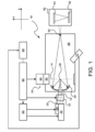
Figure 1 depicts a schematic, not-to-scale view of an overall broad conception for a laser-produced plasma EUV radiation source system; -
Figure 2 depicts a schematic, not-to-scale view of a target material metrology module; and -
Figure 3 depicts a schematic view of a part of a metrology module as may be employed in an EUV generation system of a lithographic apparatus. - With initial reference to
FIG. 1 , there is shown a schematic view of an exemplar. EUV radiation source, e.g., a laser produced plasmaEUV radiation source 10 according to one aspect of an embodiment of the presently disclosed subject matter. As shown, the EUVradiation source 10 may include a pulsed orcontinuous laser source 22, which may for example be a pulsed gas discharge CO2 laser source producing a beam 12 of radiation at a wavelength generally below 20 pm, for example, in the range of about 10.6 pm or to about 0.5 pm or less. The pulsed gas discharge CO2 laser source may have DC or RF excitation operating at high power and at a high pulse repetition rate. The EUVradiation source 10 may also include one or more modules such as aconditioning laser 23 emitting abeam 25 of conditioning radiation as explained above. - The EUV
radiation source 10 also includes atarget delivery system 24 for delivering target material in the form of liquid droplets or a continuous liquid stream. In this example, the target material is a liquid, but it could also, for example, be a solid. The target material may be made up of tin or a tin compound, although other materials could be used. In the system depicted the targetmaterial delivery system 24 introduces thedroplets 14 of the target material into the interior of avacuum chamber 26 to anirradiation region 28 where the target material may be irradiated to produce plasma. In some cases, an electrical charge is placed on the target material to permit the target material to be steered toward or away from theirradiation region 28. It should be noted that as used herein an irradiation region is a region where target material irradiation is to occur and is an irradiation region even at times when no irradiation is actually occurring. The EUV light source may also include a beam focusing andsteering system 32. - In the system shown, the components are arranged so that the
droplets 14 travel substantially horizontally. The direction from thelaser source 22 towards theirradiation region 28, that is, the nominal direction of propagation of the beam 12, may be taken as the Z axis. The path thedroplets 14 take from the targetmaterial delivery system 24 to theirradiation region 28 may be taken as the X axis. The view ofFIG. 1 is thus normal to the XZ plane. Also, while a system in which thedroplets 14 travel substantially horizontally is depicted, it will be understood by one having ordinary skill in the art that other arrangements can be used in which the droplets travel vertically or at some angle with respect to gravity between and including 90° (horizontal) and 0° (vertical). - The EUV
radiation source 10 may also include an EUV lightsource controller system 60, which may also include a laserfiring control system 65, along with thebeam steering system 32. The EUVradiation source 10 may also include a detector such as a target position detection system which may include one ormore droplet imagers 70 that generate an output indicative of the absolute or relative position of a target droplet, e.g., relative to theirradiation region 28, and provide this output to a target positiondetection feedback system 62. - The target position
detection feedback system 62 may use the output of thedroplet imager 70 to compute a target position and trajectory, from which a target error can be computed. The target error can be computed on a droplet-by-droplet basis, or on average, or on some other basis. The target error may then be provided as an input to the EUVlight source controller 60. In response, the EUVlight source controller 60 can generate a control signal such as a laser position, direction, or timing correction signal and provide this control signal to the laserbeam steering system 32. The laserbeam steering system 32 can use the control signal to change the location and/or focal power of the laser beam focal spot within thechamber 26. The laserbeam steering system 32 can also use the control signal to change the geometry of the interaction of the beam 12 and thedroplet 14. For example, the beam 12 can be made to strike thedroplet 14 off-center or at an angle of incidence other than directly head-on. - As shown in
FIG. 1 , the targetmaterial delivery system 24 may include a targetdelivery control system 90. The targetdelivery control system 90 is operable in response to a signal, for example, the target error described above, or some quantity derived from the target error provided by thesystem controller 60, to adjust the paths of thetarget droplets 14 through theirradiation region 28. This may be accomplished, for example, by repositioning the point at which atarget delivery mechanism 92 releases thetarget droplets 14. The droplet release point may be repositioned, for example, by tilting thetarget delivery mechanism 92 or by shifting thetarget delivery mechanism 92. Thetarget delivery mechanism 92 extends into thechamber 26 and is preferably externally supplied with target material and with gas from a gas source to place the target material in thetarget delivery mechanism 92 under pressure. - Continuing with
FIG. 1 , theradiation source 10 may also include one or more optical elements. In the following discussion, acollector 30 is used as an example of such an optical element, but the discussion applies to other optical elements as well. Thecollector 30 may be a normal incidence reflector, for example, implemented as a multilayer mirror (MEM) fabricated by depositing many pairs of Mo and Si layers on a substrate with additional thin barrier layers, for example B4C, ZrC, S 13N4 or C, deposited at each interface between layer pairs to effectively block thermally- induced interlayer diffusion, but thecollector 30 may be formed of other layers of material in other embodiments . Thecollector 30 may be in the form of a prolate ellipsoid, with a central aperture to allow the laser beam 12 to pass through and reach theirradiation region 28. Thecollector 30 may be, e.g., in the shape of an ellipsoid that has a first focus at theirradiation region 28 and a second focus at a so-called intermediate point 40 (also called the intermediate focus 40) where the EUV radiation may be output from theEUV radiation source 10 and input to, e.g., an integrated circuit lithography scanner orstepper 50. The scanner orstepper 50 uses the radiation, for example, to process asilicon wafer workpiece 52 in a known manner using a reticle ormask 54. Thesilicon wafer workpiece 52 is then additionally processed in a known manner to obtain integrated circuit devices. - As mentioned, in general, for a reference coordinate system, Z is the direction along which the laser beam 12 propagates and is also the direction from the
collector 30 to theirradiation site 28 and the EUVintermediate focus 40. X is in the droplet propagation plane. Y is orthogonal to the XZ plane. To make this a right-handed coordinate system, the trajectory of thedroplets 14 is taken to be in the -X direction. - In the example shown, the
target material 14 is in the form of a stream of droplets released by atarget material dispenser 92, which in the example is a droplet generator. Thetarget material droplet 14 can be ionized by a main pulse in this form. Alternatively, thetarget material 14 can be preconditioned for ionization with aconditioning pulse 25 that can, for example, change the geometric distribution of thetarget material 14. Thus, it may be necessary both to hit thetarget material 14 accurately with the conditioning pulse to ensure thetarget material 14 is in the desired form (disk, cloud, etc.), and to hit the target accurately with the main pulse to promote efficient production of EUV radiation. - As used herein, the term "irradiation site" is used to connote the
position 28 in thechamber 26 where thetarget material 14 is struck with a main pulse. It may coincide with the primary focus of thecollector mirror 30. - As mentioned, one droplet detection metrology utilizes darkfield illumination, where the backscatter from a droplet passing through a laser curtain is collected near the primary focus. The metrology module detects the droplet crossing at a specific location in space to provide a trigger to the system controls to enable all ensuing sequences to generate EUV light. An example of such a system is shown schematically in
FIG. 2 , in which adroplet detection controller 122 causes a droplet illumination module (DIM) 124 to illuminate adroplet 14. A droplet detection module (DDM) 126 detects the radiation backscattered by the droplet to permit thedroplet detection controller 122 to derive information such as the position of thedroplet 14. Note that herein, the form of the target material is referred to as a droplet even if one or more conditioning pulses have altered the target material from a true droplet form. The detection process described above in connection withFIG. 2 may be used to detect the droplets after they have fully coalesced from smaller droplets and tune the operation of the droplet generator. - In other embodiments, the EUV generation system may be based on laser powered plasma, LPP. The droplet of target material is conditioned in that the droplet of target material is first irradiated by a pre-pulse which changes a shape of the droplet, e.g. into a disk shape, followed by the irradiation of the thus shaped droplet by a rarefaction pulse to generate a plasma of the target material. The main pulse may then be irradiated to the plasma of the target material.
-
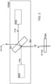
Figure 3 depicts a schematic view of a metrology module. The metrology module comprises a polarization state dependent beam pickup PDBP and a polarization state adjuster PSA. The polarization state adjuster PSA is arranged downstream of the polarization state dependent beam pickup PDBP to adjust a polarization state of a forward beam PP-FB, as explained below. The forward beam, such as the forward beam of the pre-pulse PP generated by a pre-pulse generator, is incident on the polarization state dependent beam pickup PDBP. A portion of the forward beam is split by the polarization state dependent beam pickup, the portion being provided to a forward beam sensor FBS configured to sense the portion of the forward beam. The remainder of the forward beam is transmitted by the polarization state dependent beam pickup to the polarization state adjuster. The polarization state adjuster is configured to adjust, i.e. change, a polarization state of the forward beam. The forward beam, with changed polarization state, is transmitted to the droplet of target material. A portion of the forward beam is reflected off the droplet of target material, to form a reverse beam PP-RB. The reverse beam is incident on the polarization state adjuster, where the polarization state of the reverse beam is adjusted, i.e. changed, and then the reverse beam PP-RB further propagates to the polarization state dependent beam pickup, where a portion of the reverse beam is split to propagate to the reverse beam sensor RBS. At the polarization state dependent beam pickup, the reverse beam that reaches the polarization state dependent beam pickup has twice been subjected to polarization state change by the polarization state adjuster, namely a change of the polarization state of the forward beam towards the droplet of target material and a change of the polarization state of the reverse beam. The twice changed polarization state of the reverse beam incident at the polarization stated dependent beam pickup may differ from the polarization state of the forward beam incident at the polarization stated dependent beam pickup. As the beam pickup is polarization state dependent, i.e. the portions split from the forward and reverse beams may depend on the polarization state. - The amount of energy reflected by the droplet of target material may be small. As a consequence, an intensity of the reverse beam may be smaller than an intensity of the forward beam. For example, the intensity of the reverse beam may be substantially smaller than the intensity of the forward beam. In such case a signal to noise ratio of measurement of the portion of the forward beam by the forward beam sensor may for example be substantially higher than a signal to noise ratio of the measurement of the portion of the return beam by the return beam sensor. The ability to split different portions of the forward beam and of the reverse beam, may enable to take account of the (e.g. substantial) difference in intensity of the forward beam and the reverse beam. For example, the portion of the return beam split by the polarization dependent beam pickup may be substantially larger than the portion of the forward beam split by the polarization state dependent beam pickup. As a consequence, an intensity of the portion of the reverse beam as received by reverse beam sensor may be increased. Thereby, a signal to noise ratio of the measurement of the reverse beam at the reverse beam sensor may be enhanced, which may enable to more accurately measure the reverse beam. As the metrology module may determine a position of the droplet of target material using the measurement of the reverse beam reflected from the droplet of target material, a position of the droplet of target material may be determined more accurately.
- Reverting to
Figure 3 in some more detail, the polarization state dependent beam pickup comprises two surfaces, indicated by S1 and S2. The forward beam is incident on the first surface S1 of the polarization state dependent beam pickup where it is diffracted and propagates to the second surface S2 of the polarization state dependent beam pickup. The second surface may comprise a polarization dependent coating, which reflects a portion of the forward beam and diffracts the remainder of the forward beam. The portion that is reflected on the second surface propagates back to the first surface, where it is diffracted to propagate to the forward beam sensor. The remainder of the forward beam, which is diffracted at the second surface, propagates to the polarization state adjuster. - The reverse beam, after having propagated through the polarization state adjuster, where the polarization of the reverse beam is changed, is incident on the second surface S2 of the polarization dependent beam pickup at the second surface, a portion of the reverse beam is reflected and propagates to the reverse beam sensor. The remainder of the reverse beam is diffracted at the second surface, propagates to the first surface, where it is again diffracted and to propagate towards the light source of the forward beam.
- The second surface may be provided with a polarization dependent coating whereby a portion reflected by the coating depends on the polarization state of the beam, i.e. the forward and reverse beam.
- For example, at the polarization state dependent beam pickup, the polarization state of one of the forward beam and the reverse beam may be horizontal and the polarization state of the other one of the forward and the reverse beam may be vertical. The polarization state dependent beam pickup may be arranged to pick up a horizontal polarization state portion of a horizontal polarization state of the beam and a vertical polarization state portion of a vertical polarization state of the beam, wherein the horizontal polarization state portion differs from the vertical polarization state portion. The forward beam may be a laser beam having a vertical or horizontal polarization. For example, the forward beam as emitted by a laser is p (vertically) polarized while the return beam, of which the polarization is changed twice by the polarization state adjuster, is s (horizontally) polarized, as represented by p (denoting vertical polarization) and s (denoting horizontal polarization) in
Figure 3 . Accordingly, with the opposite polarizations, i.e. vertical and horizontal, a large difference in the properties of the polarization state dependent beam pickup may be achieved: at one of the vertical and horizontal polarization directions, the portion split from the beam may be large while with the other one of the vertical and horizontal polarization directions, the portion split from the beam may be small. Thus, a large difference in the portions split from the forward and reverse beam may be achieved. - For example, the second surface may exhibit a high reflectance for s polarization and a low reflectance for p polarization. Accordingly, in case the forward beam is p polarized, and the reverse beam is s polarized, a small portion of the forward beam is split (reflected) while a large portion of the reverse beam is split (reflected), thereby enabling to enhance a signal to noise ratio of the measurement of the reverse beam at the reverse beam sensor. The polarization state dependent beam pickup may be configured to split a portion of the forward beam and a portion of the reverse beam by reflecting the respective portions while diffracting the remainders of the forward and reverse beams.
- For example, taking account of the polarization state dependent properties of reflection at a surface of the polarization state dependent beam pickup, the horizontal polarization state portion may exceed the vertical polarization state portion to obtain at the reverse beam sensor a large portion of the reverse beam having a horizontal polarization state and to obtain at the forward beam sensor a small(er) portion of the forward beam having a vertical polarization state. The difference in polarization state dependent reflectivity may be high, e.g. exceeding a
factor 10, the reflectivity for s polarization state may e.g. be at least afactor 10 higher than the reflectivity of the p polarization state. As a result, the horizontal polarization state portion may exceed the vertical polarization state portion by a factor of at least 10. As an example, the polarization state dependent beam pickup may be configured to split a portion of 2 % at vertical polarization state (p) and a portion of 60% at horizontal polarization state (s). Thus, with a forward beam having the vertical polarization state, 2% may be split to the forward beam sensor, while a reverse beam having the horizontal polarization state, 60% may be split to the reverse beam sensor. - The polarization state adjuster may comprise any optical element to capable of changing a polarization state. In an embodiment, the polarization state adjuster comprises a quarter wave plate. The quarter wave pate is configured to change the polarization state of a beam from vertical (p) to circular. Furthermore, the quarter wave plate is configured to change the polarization state of a beam from circular to horizontal (s). Accordingly, quarter wave plate may change the polarization in a well defined way. The quarter wave plate may for example be position in the forward beam path and in the reverse beam path. Reverting to the above example of a forward beam emitted by a forward beam light source, the forward beam having a p polarization state, the quarter wave plate may change the polarization of the forward beam from p (i.e. vertical) to circular, i.e. in the forward beam path, while the quarter wave plate changing the polarization state of the reverse beam reflected from the droplet of target material from circular to s (i.e. horizontal). Thus, the forward beam incident at the polarization state dependent beam pickup exhibits the p polarization state while the reverse beam incident at the polarization state dependent beam pickup exhibits the s polarization state, as explained above.
- The forward beam FB as described above may be a pre-pulse PP configured to condition the droplet of target material. The Laser Powered Plasma based EUV generation system may further be configured to guide a rarefaction pulse through the polarization state dependent beam pickup and the polarization state adjuster, to facilitate alignment of the pre-pulse and the rarefaction pulse. Furthermore, the polarization dependent beam pickup may be configured to split a portion of the rarefaction pulse, which them propagates to the forward beam sensor. The forward beam sensor may thereby be used to further sense the portion of the rarefaction pulse, thus enabling to make use of the same sensor.
- Although specific reference may be made in this text to the use of lithographic apparatus in the manufacture of ICs, it should be understood that the lithographic apparatus described herein may have other applications. Possible other applications include the manufacture of integrated optical systems, guidance and detection patterns for magnetic domain memories, flat-panel displays, liquid-crystal displays (LCDs), thin-film magnetic heads, etc.
- Although specific reference may be made in this text to embodiments of the invention in the context of a lithographic apparatus, embodiments of the invention may be used in other apparatus. Embodiments of the invention may form part of a mask inspection apparatus, a metrology apparatus, or any apparatus that measures or processes an object such as a wafer (or other substrate) or mask (or other patterning device). These apparatus may be generally referred to as lithographic tools. Such a lithographic tool may use vacuum conditions or ambient (non-vacuum) conditions.
- Where the context allows, embodiments of the invention may be implemented in hardware, firmware, software, or any combination thereof. Embodiments of the invention may also be implemented as instructions stored on a machine-readable medium, which may be read and executed by one or more processors. A machine-readable medium may include any mechanism for storing or transmitting information in a form readable by a machine (e.g., a computing device). For example, a machine-readable medium may include read only memory (ROM); random access memory (RAM); magnetic storage media; optical storage media; flash memory devices; electrical, optical, acoustical or other forms of propagated signals (e.g. carrier waves, infrared signals, digital signals, etc.), and others. Further, firmware, software, routines, instructions may be described herein as performing certain actions. However, it should be appreciated that such descriptions are merely for convenience and that such actions in fact result from computing devices, processors, controllers, or other devices executing the firmware, software, routines, instructions, etc. and in doing that may cause actuators or other devices to interact with the physical world.
- While specific embodiments of the invention have been described above, it will be appreciated that the invention may be practiced otherwise than as described. The descriptions above are intended to be illustrative, not limiting. Thus it will be apparent to one skilled in the art that modifications may be made to the invention as described without departing from the scope of the claims set out below.
Claims (15)
- A laser powered plasma, LPP, based EUV generation system configured to generate EUV light by irradiating droplets of a target material with at least one laser beam, the system comprising a metrology module configured to determine a position of a droplet of the target material by comparing a portion of a forward beam with a portion of a reverse beam that is reflected off from the target material, wherein the metrology module comprises:- a polarization state dependent beam pickup arranged to split a portion from the forward beam and a portion from the reverse beam, wherein the portions depend on a polarization state of forward and reverse beam incident on the polarization state dependent beam pickup, and- a polarization state adjuster arranged downstream of a beam path when compared to the polarization state dependent beam pickup, wherein the polarization state adjuster is arranged to change a polarization state of at least one of the forward beam and the reverse beam such that the polarization state of the reverse beam incident at the polarization state dependent beam pickup differs from the polarization state of the forward beam incident at the polarization state dependent beam pickup.
- The LPP based EUV generation system according to any one of the preceding claims, wherein the polarization state dependent beam pickup is arranged to pick up a horizontal polarization state portion of a horizontal polarization state of the beam and a vertical polarization state portion of a vertical polarization state of the beam, wherein the horizontal polarization state portion differs from the vertical polarization state portion.
- The LPP based EUV generation system according to polarization state dependent beam pickup comprises a surface exhibiting a polarization state dependent reflectivity.
- The LPP based EUV generation system according to claim 2 or 3, wherein the horizontal polarization state portion exceeds the vertical polarization state portion.
- The LPP based EUV generation system according to claim 4, wherein the horizontal polarization state portion exceeds the vertical polarization state portion by a factor of at least 10.
- The LPP based EUV generation system according to any one of claims 2-5, wherein the polarization state dependent beam pickup is arranged to direct the portion from the forward beam to a forward beam sensor and to direct the portion from the reverse beam to a reverse beam sensor.
- The LPP based EUV generation system according to any one of the preceding claims, wherein the polarization state adjuster comprises a Quarter Wave plate.
- The LPP based EUV generation system according to any one of the preceding claims, wherein the polarization state adjuster is positioned in the forward beam path of the forward beam and in the reverse beam path of the reverse beam.
- The LPP based EUV generation system according to any one of the preceding claims, further configured to guide a rarefaction pulse through the polarization state dependent beam pickup and the polarization state adjuster.
- The LPP based EUV generation system according to any one of the preceding claims, wherein a wavelength of the forward beam is below 1500nm, preferably 1064nm or lower.
- A lithographic apparatus comprising the laser powered plasma, LPP based EUV generation system according to any one of the preceding claims.
- A method of generating EUV by laser powered plasma, LPP, wherein EUV light is generated by irradiating droplets of a target material with at least one laser beam, the method comprising determining by a metrology module a position of a droplet of the target material by comparing a portion of a forward beam with a portion of a reverse beam that is reflected off from the target material, wherein the metrology module comprises:- a polarization state dependent beam pickup arranged to split a portion from the forward beam and a portion from the reverse beam, wherein the portions depend on a polarization state of forward and reverse beam incident on the polarization state dependent beam pickup, and- a polarization state adjuster arranged downstream of a beam path when compared to the polarization state dependent beam pickup, wherein the polarization state adjuster is arranged to change a polarization state of at least one of the forward beam and the reverse beam such that the polarization state of the reverse beam incident at the polarization state dependent beam pickup differs from the polarization state of the forward beam incident at the polarization state dependent beam pickup.
- The method of generating EUV by laser powered plasma, LPP according to claim 12, wherein the polarization state dependent beam pickup is arranged to pick up a horizontal polarization state portion of a horizontal polarization state of the beam and a vertical polarization state portion of a vertical polarization state of the beam, wherein the horizontal polarization state portion differs from the vertical polarization state portion.
- The method of generating EUV by laser powered plasma, LPP according to claim 13, wherein the horizontal polarization state portion exceeds the vertical polarization state portion.
- The method of generating EUV by laser powered plasma, LPP according to any one of claims 12 or 14, wherein the polarization state adjuster comprises a Quarter Wave plate.
Priority Applications (3)
| Application Number | Priority Date | Filing Date | Title |
|---|---|---|---|
| EP23214202.6A EP4568425A1 (en) | 2023-12-05 | 2023-12-05 | Laser powered plasma based euv generation system |
| PCT/EP2024/082211 WO2025119612A1 (en) | 2023-12-05 | 2024-11-13 | Laser powered plasma based euv generation system |
| TW113146912A TW202531786A (en) | 2023-12-05 | 2024-12-04 | Laser powered plasma based euv generation system |
Applications Claiming Priority (1)
| Application Number | Priority Date | Filing Date | Title |
|---|---|---|---|
| EP23214202.6A EP4568425A1 (en) | 2023-12-05 | 2023-12-05 | Laser powered plasma based euv generation system |
Publications (1)
| Publication Number | Publication Date |
|---|---|
| EP4568425A1 true EP4568425A1 (en) | 2025-06-11 |
Family
ID=89119261
Family Applications (1)
| Application Number | Title | Priority Date | Filing Date |
|---|---|---|---|
| EP23214202.6A Withdrawn EP4568425A1 (en) | 2023-12-05 | 2023-12-05 | Laser powered plasma based euv generation system |
Country Status (3)
| Country | Link |
|---|---|
| EP (1) | EP4568425A1 (en) |
| TW (1) | TW202531786A (en) |
| WO (1) | WO2025119612A1 (en) |
Citations (2)
| Publication number | Priority date | Publication date | Assignee | Title |
|---|---|---|---|---|
| US20140333915A1 (en) * | 2011-12-06 | 2014-11-13 | Asml Netherlands B.V. | Radiation Source |
| US10048199B1 (en) * | 2017-03-20 | 2018-08-14 | Asml Netherlands B.V. | Metrology system for an extreme ultraviolet light source |
-
2023
- 2023-12-05 EP EP23214202.6A patent/EP4568425A1/en not_active Withdrawn
-
2024
- 2024-11-13 WO PCT/EP2024/082211 patent/WO2025119612A1/en active Pending
- 2024-12-04 TW TW113146912A patent/TW202531786A/en unknown
Patent Citations (2)
| Publication number | Priority date | Publication date | Assignee | Title |
|---|---|---|---|---|
| US20140333915A1 (en) * | 2011-12-06 | 2014-11-13 | Asml Netherlands B.V. | Radiation Source |
| US10048199B1 (en) * | 2017-03-20 | 2018-08-14 | Asml Netherlands B.V. | Metrology system for an extreme ultraviolet light source |
Non-Patent Citations (1)
| Title |
|---|
| "A MODULE FOR A LASER-PRODUCED PLASMA RADIATION SOURCE", vol. 713, no. 59, 7 August 2023 (2023-08-07), XP007151657, ISSN: 0374-4353, Retrieved from the Internet <URL:https://www.researchdisclosure.com/database/RD713059> [retrieved on 20230807] * |
Also Published As
| Publication number | Publication date |
|---|---|
| TW202531786A (en) | 2025-08-01 |
| WO2025119612A1 (en) | 2025-06-12 |
Similar Documents
| Publication | Publication Date | Title |
|---|---|---|
| JP6401283B2 (en) | System and method for controlling droplets of a target material in an EUV light source | |
| US12171053B2 (en) | System for monitoring a plasma | |
| US9986628B2 (en) | Method and apparatus for generating radiation | |
| US11467498B2 (en) | Extreme ultraviolet control system | |
| CN112771999B (en) | Laser systems for target metrology and modification in EUV sources | |
| US6690764B2 (en) | X-ray sources that maintain production of rotationally symmetrical x-ray flux during use | |
| US10490313B2 (en) | Method of controlling debris in an EUV light source | |
| JP2018536199A (en) | EUV source chamber and gas flow mode for a lithographic apparatus, multilayer mirror, and lithographic apparatus | |
| WO2019192841A1 (en) | Spatial modulation of a light beam | |
| KR20150140324A (en) | Source collector apparatus, lithographic apparatus and method | |
| US11153959B2 (en) | Apparatus and method for generating extreme ultraviolet radiation | |
| US20200178380A1 (en) | Method and device for measuring contamination in euv source | |
| TW201313075A (en) | Radiation source and lithography device | |
| WO2025119612A1 (en) | Laser powered plasma based euv generation system | |
| US9645500B2 (en) | Radiation source and lithographic apparatus | |
| KR102901744B1 (en) | Measurement system for use with optical amplification cavities | |
| TWI825198B (en) | Extreme ultraviolet (euv) light source and apparatus for the same, apparatus for forming optical pulse, and method of adjusting property of optical pulse | |
| US20240361222A1 (en) | Droplet detection metrology utilizing metrology beam scattering | |
| WO2025140811A1 (en) | Extreme ultraviolet light generation sequence for an extreme ultraviolet light source | |
| CN118648198A (en) | Laser beam steering system and method | |
| WO2023126106A1 (en) | Laser beam steering system and method | |
| WO2025026646A1 (en) | A module for a laser-produced plasma radiation source | |
| NL2012718A (en) | Radiation systems and associated methods. |
Legal Events
| Date | Code | Title | Description |
|---|---|---|---|
| PUAI | Public reference made under article 153(3) epc to a published international application that has entered the european phase |
Free format text: ORIGINAL CODE: 0009012 |
|
| STAA | Information on the status of an ep patent application or granted ep patent |
Free format text: STATUS: THE APPLICATION HAS BEEN PUBLISHED |
|
| AK | Designated contracting states |
Kind code of ref document: A1 Designated state(s): AL AT BE BG CH CY CZ DE DK EE ES FI FR GB GR HR HU IE IS IT LI LT LU LV MC ME MK MT NL NO PL PT RO RS SE SI SK SM TR |
|
| STAA | Information on the status of an ep patent application or granted ep patent |
Free format text: STATUS: THE APPLICATION IS DEEMED TO BE WITHDRAWN |
|
| 18D | Application deemed to be withdrawn |
Effective date: 20251212 |