EP4568232A1 - Verfahren und system zur steuerung des leistungsschalters eines fahrzeugs - Google Patents
Verfahren und system zur steuerung des leistungsschalters eines fahrzeugs Download PDFInfo
- Publication number
- EP4568232A1 EP4568232A1 EP24217123.9A EP24217123A EP4568232A1 EP 4568232 A1 EP4568232 A1 EP 4568232A1 EP 24217123 A EP24217123 A EP 24217123A EP 4568232 A1 EP4568232 A1 EP 4568232A1
- Authority
- EP
- European Patent Office
- Prior art keywords
- vehicle
- instruction
- power switch
- network
- moving state
- Prior art date
- Legal status (The legal status is an assumption and is not a legal conclusion. Google has not performed a legal analysis and makes no representation as to the accuracy of the status listed.)
- Pending
Links
Images


Classifications
-
- H—ELECTRICITY
- H04—ELECTRIC COMMUNICATION TECHNIQUE
- H04L—TRANSMISSION OF DIGITAL INFORMATION, e.g. TELEGRAPHIC COMMUNICATION
- H04L67/00—Network arrangements or protocols for supporting network services or applications
- H04L67/01—Protocols
- H04L67/1396—Protocols specially adapted for monitoring users' activity
-
- B—PERFORMING OPERATIONS; TRANSPORTING
- B60—VEHICLES IN GENERAL
- B60L—PROPULSION OF ELECTRICALLY-PROPELLED VEHICLES; SUPPLYING ELECTRIC POWER FOR AUXILIARY EQUIPMENT OF ELECTRICALLY-PROPELLED VEHICLES; ELECTRODYNAMIC BRAKE SYSTEMS FOR VEHICLES IN GENERAL; MAGNETIC SUSPENSION OR LEVITATION FOR VEHICLES; MONITORING OPERATING VARIABLES OF ELECTRICALLY-PROPELLED VEHICLES; ELECTRIC SAFETY DEVICES FOR ELECTRICALLY-PROPELLED VEHICLES
- B60L2200/00—Type of vehicles
- B60L2200/12—Bikes
-
- B—PERFORMING OPERATIONS; TRANSPORTING
- B60—VEHICLES IN GENERAL
- B60L—PROPULSION OF ELECTRICALLY-PROPELLED VEHICLES; SUPPLYING ELECTRIC POWER FOR AUXILIARY EQUIPMENT OF ELECTRICALLY-PROPELLED VEHICLES; ELECTRODYNAMIC BRAKE SYSTEMS FOR VEHICLES IN GENERAL; MAGNETIC SUSPENSION OR LEVITATION FOR VEHICLES; MONITORING OPERATING VARIABLES OF ELECTRICALLY-PROPELLED VEHICLES; ELECTRIC SAFETY DEVICES FOR ELECTRICALLY-PROPELLED VEHICLES
- B60L2240/00—Control parameters of input or output; Target parameters
- B60L2240/70—Interactions with external data bases, e.g. traffic centres
-
- B—PERFORMING OPERATIONS; TRANSPORTING
- B60—VEHICLES IN GENERAL
- B60L—PROPULSION OF ELECTRICALLY-PROPELLED VEHICLES; SUPPLYING ELECTRIC POWER FOR AUXILIARY EQUIPMENT OF ELECTRICALLY-PROPELLED VEHICLES; ELECTRODYNAMIC BRAKE SYSTEMS FOR VEHICLES IN GENERAL; MAGNETIC SUSPENSION OR LEVITATION FOR VEHICLES; MONITORING OPERATING VARIABLES OF ELECTRICALLY-PROPELLED VEHICLES; ELECTRIC SAFETY DEVICES FOR ELECTRICALLY-PROPELLED VEHICLES
- B60L2260/00—Operating Modes
- B60L2260/20—Drive modes; Transition between modes
- B60L2260/22—Standstill, e.g. zero speed
-
- B—PERFORMING OPERATIONS; TRANSPORTING
- B60—VEHICLES IN GENERAL
- B60L—PROPULSION OF ELECTRICALLY-PROPELLED VEHICLES; SUPPLYING ELECTRIC POWER FOR AUXILIARY EQUIPMENT OF ELECTRICALLY-PROPELLED VEHICLES; ELECTRODYNAMIC BRAKE SYSTEMS FOR VEHICLES IN GENERAL; MAGNETIC SUSPENSION OR LEVITATION FOR VEHICLES; MONITORING OPERATING VARIABLES OF ELECTRICALLY-PROPELLED VEHICLES; ELECTRIC SAFETY DEVICES FOR ELECTRICALLY-PROPELLED VEHICLES
- B60L2260/00—Operating Modes
- B60L2260/20—Drive modes; Transition between modes
- B60L2260/26—Transition between different drive modes
Definitions
- the disclosure relates to a method and a system for controlling a power switch of a vehicle, and more particularly to a method and a system where a remote server can be utilized to control a power switch of a vehicle over a network.
- an object of the disclosure is to provide a power-switch control system for a vehicle and a method for controlling a power switch of a vehicle that can alleviate at least one of the drawbacks of the prior art.
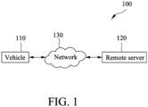
- FIG. 1 illustrates a power-switch control system 100 for a vehicle according to an embodiment of the present disclosure.
- the power-switch control system 100 at least includes a vehicle 110 and a remote server 120.
- the vehicle 110 and the remote server 120 can be coupled to each other via a network 130.
- the network 130 may be a wired network, a telecommunications network, or a wireless network (such as a Bluetooth ® network, a Wi-Fi network or the like).
- the vehicle 110 may be a traditional vehicle (e.g., a gasoline car or a motorcycle) that uses petroleum as an energy source.
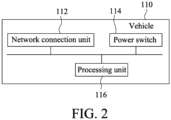
- FIG. 2 illustrates the vehicle 110 according to an embodiment of the disclosure.
- the vehicle 110 may at least include a network connection unit 112, a power switch 114 (also known as an ignition switch) for ignition, and a processing unit 116.
- the network connection unit 112 may connect to a network, so as to enable the vehicle 110 to have network connectivity.
- the network may be a wired network, a telecommunications network, or a wireless network such as a Bluetooth ® network, a Wi-Fi network or the like. Turning the power switch 114 on or off would activate the main electrical systems for the vehicle 110 and enable the vehicle 110 to be powered on or off.
- the processing unit 116 is coupled to the network connection unit 112 and the power switch 114, and is configured to control operations of all the hardware and software in the vehicle 110, and to cooperate with the remote server 120 (see Figure 1 ) to implement a method for controlling a power switch of a vehicle of the present disclosure. Details will be discussed later.
- the vehicle 110 may be an electric vehicle (e.g., an electric car or an electric motorcycle) that uses electricity as an energy source.
- Figure 3 illustrates an electric vehicle 300 according to an embodiment of the disclosure.
- the electric vehicle 300 according to the embodiment of the present disclosure may be an electric carrier (for example, an electric automobile or an electric motorcycle) that is powered with a battery serving as an energy source.
- the electric vehicle 300 at least includes a battery storage unit 310, a network connection unit 320, a power switch 330, a motor unit 340 and a processing unit 350.
- the battery storage unit 310 is configured to receive at least one battery, such as a battery 312.
- the battery 312 may be a battery module that includes at least one battery cell for storing and releasing electricity.
- the at least one battery may be connected in series or in parallel to provide electricity to the motor unit 340 of the electric vehicle 300 for operation.
- the network connection unit 320 may connect to a network so as to enable the electric vehicle 300 to have network connectivity.
- the network may be a wired network, a telecommunications network or a wireless network (such as a Bluetooth ® network, a Wi-Fi network or the like). Turning the power switch 330 on or off would activate the main electrical systems for the electric vehicle 300 and enable the electric vehicle 300 to be powered on or off.
- the motor unit 340 is configured to operate to drive the electric vehicle 300 and other components of the electric vehicle 300 that operate in virtue of rotation.
- the processing unit 350 is coupled to the aforementioned elements, and is configured to control operations of all hardware and software in the electric vehicle 300 and to cooperate with the remote server 120 (see Figure 1 ) to implement the method of the present disclosure. Details will be discussed later. It is noted that in some embodiments, the electric vehicle 300 may include a storage unit (not shown in the drawings). The storage unit may store relevant information regarding the electric vehicle 300 and/or the battery 312.
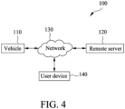
- FIG. 4 illustrates a power-switch control system 100 for a vehicle according to another embodiment of the present disclosure.
- the power-switch control system 100 for a vehicle according to the embodiment of the present disclosure at least includes a vehicle 110, a remote server 120 and a user device 140.
- the vehicle 110, the remote server 120 and the user device 140 may be coupled to each other via a network 130.
- the network 130 may be a wired network, a telecommunications network or a wireless network (such as a Bluetooth ® network, a Wi-Fi network or the like).
- the user device 140 may be a mobile device (such as a smartphone) that corresponds to a user of the vehicle 110.
- the aforementioned user device 140 is merely an example for the present disclosure, and the present disclosure is not limited thereto. It is noted that the user device 140 may be paired with and be connected to the vehicle 110 for performing data transmission. It is noted that the remote server 120 may be an electronic device. The remote server 120 may simultaneously manage a plurality of vehicles that are located at one location or are located at different locations via the network 130, and a plurality of charging stations. It is reminded that the charging stations may include a plurality of batteries for provision to at least one vehicle (such as an electric motorcycle or an electric car) for access. The vehicle 110, the remote server 120 and the user device 140 may cooperate to implement the method of the present disclosure, and the details thereof will be explained later.
- Figure 5 illustrates the method for controlling a power switch of a vehicle according to an embodiment of the present disclosure.
- the method according to the embodiment of the present disclosure is adapted to be used on a vehicle and a remote server.
- the remote server is utilized to determine whether it is feasible to connect to the vehicle via a network.
- the network may be a wired network, a telecommunications network or a wireless network (such as a Bluetooth ® network, a Wi-Fi network or the like).
- the remote server transmits a first instruction to the vehicle via the network. It is noted that the first instruction is used to turn on or off a power switch of the vehicle.
- the remote server cancels transmission of the first instruction.
- step S550 the vehicle (more specifically, a processing unit of the vehicle) determines whether the vehicle is in a moving state.
- the vehicle determines whether the vehicle is in a moving state.
- step S570 the vehicle ignores the first instruction. In other words, the first instruction will not be executed when the vehicle is in the moving state.
- step S580 the vehicle controls, in response to the first instruction, the power switch of the vehicle to turn the power switch on or off.
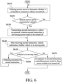
- Figure 6 illustrates the method for controlling a power switch of a vehicle according to another embodiment of the present disclosure.
- the method according to the embodiment of the present disclosure is adapted to be used on a vehicle and a remote server.
- the remote server is utilized to determine whether it is feasible to connect to the vehicle via a network.
- the network may be a wired network, a telecommunications network or a wireless network (such as a Bluetooth ® network, a Wi-Fi network or the like).
- a flow of the method returns to step S610.
- the remote server transmits a second instruction to the vehicle via the network. It is noted that the second instruction is used to force a power switch of the vehicle to be turned off.
- step S640 the vehicle (more specifically, a processing unit of the vehicle) determines whether the vehicle is in a moving state.
- the vehicle determines whether the vehicle is in a moving state.
- step S660 execution of the second instruction is delayed, and the flow returns to step S640 to keep determining whether the vehicle is in the moving state.
- step S670 the vehicle controls, in response to the second instruction, the power switch of the vehicle so as to force the power switch to be turned off.
- the vehicle delays execution of the second instruction until the vehicle is not in the moving state, at which time the second instruction is executed for turning off the power switch of the vehicle.
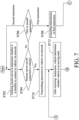
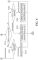
- Figures 7 and 8 cooperatively illustrate the method for controlling a power switch of a vehicle according to still another embodiment of the present disclosure.
- the method according to the embodiment of the present disclosure is adapted to be used on a vehicle and a remote server.
- the remote server is utilized to determine whether it is feasible to connect to the vehicle via a network.
- the network may be a wired network, a telecommunications network or a wireless network (such as a Bluetooth ® network, a Wi-Fi network or the like).
- the remote server determines whether an instruction transmitted this time by the remote server is a first instruction or a second instruction . It is noted that the first instruction is used to turn on or off a power switch of the vehicle, and the second instruction is used to force the power switch of the vehicle to be turned off.
- the flow returns to step S702.
- the remote server cancels transmission of the first instruction.
- the remote server is capable of being connected to the vehicle via the network (Yes in step S704), as shown in step S710, the remote server transmits the instruction to the vehicle via the network.
- the vehicle determines whether the vehicle is in a moving state.
- the vehicle determines whether the instruction received by the vehicle is the first instruction or the second instruction.
- the flow returns to step S712.
- the vehicle ignores the first instruction. In other words, the first instruction is not executed when the vehicle is in the moving state.
- the vehicle determines whether the instruction received by the vehicle is the first instruction or the second instruction.
- the vehicle controls the power switch of the vehicle to turn the power switch on or off.
- the vehicle controls the power switch of the vehicle to force the power switch to be turned off.
- the vehicle delays execution of the second instruction until the vehicle is not in the moving state, at which time the second instruction is executed for turning off the power switch of the vehicle.
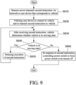
- Figure 9 illustrates the method for controlling a power switch of a vehicle according to further another embodiment of the present disclosure.
- the method according to the embodiment of the present disclosure is adapted to be used on a vehicle, a user device and a remote server.
- the remote server transmits a second instruction to the user device that corresponds to the vehicle via a network.
- the network may be a wired network, a telecommunications network or a wireless network (such as a Bluetooth ® network, a Wi-Fi network or the like).
- the second instruction is used to force a power switch of the vehicle to be turned off.
- the user device is utilized to connect to the vehicle via the network (such as a Wi-Fi network or a Bluetooth network), and to transmit the second instruction to the vehicle.
- step S830 the vehicle (more specifically, a processing unit of the vehicle) determines whether the vehicle is in a moving state.
- the vehicle determines whether the vehicle is in a moving state.
- execution of the second instruction is delayed, and the flow returns to step S830 to keep determining whether the vehicle is in the moving state or not.
- the vehicle controls, in response to the second instruction, the power switch of the vehicle to force the power switch to be turned off.
- the vehicle delays execution of the second instruction until the vehicle is not in the moving state, at which time the second instruction is executed for turning off the power switch of the vehicle.
- the remote server can be utilized to control the power switch of the vehicle via the network, thereby providing a mechanism for management and control that is relatively more flexible and appropriate, which provides users with a better experience, and protects the rights and interests of business owners.
- the method of the present invention may be implemented as a set of program codes.
- the set of program codes may be stored in a physical storage medium, such as a floppy disk, a compact disk, a hard disk, or any machine-readable (e.g., computer-readable) storage medium, or may be implemented as a computer program product that is not limited in the physical form.
- a machine e.g., a computer
- the machine turns into a device for implementing the method of the present invention.
- the program codes may also be transmitted by a transmission medium, such as one or more wires, cables, optical fibers, or any other transmission means, and when the program codes are received, loaded, and executed by a machine (e.g., a computer), such machine turns into a device for implementing the method of the present invention.
- a machine e.g., a computer
- the program codes When the method is implemented by a general purpose processor, the program codes cause the processor to operate as a specific device having a function similar to an application-specific integrated circuit (ASIC).
- ASIC application-specific integrated circuit
Landscapes
- Engineering & Computer Science (AREA)
- Computer Networks & Wireless Communication (AREA)
- Signal Processing (AREA)
- Electric Propulsion And Braking For Vehicles (AREA)
- Selective Calling Equipment (AREA)
- Remote Monitoring And Control Of Power-Distribution Networks (AREA)
- Traffic Control Systems (AREA)
Applications Claiming Priority (1)
| Application Number | Priority Date | Filing Date | Title |
|---|---|---|---|
| TW112147232A TWI870139B (zh) | 2023-12-05 | 2023-12-05 | 車輛之電門控制方法及系統 |
Publications (1)
| Publication Number | Publication Date |
|---|---|
| EP4568232A1 true EP4568232A1 (de) | 2025-06-11 |
Family
ID=93796796
Family Applications (1)
| Application Number | Title | Priority Date | Filing Date |
|---|---|---|---|
| EP24217123.9A Pending EP4568232A1 (de) | 2023-12-05 | 2024-12-03 | Verfahren und system zur steuerung des leistungsschalters eines fahrzeugs |
Country Status (3)
| Country | Link |
|---|---|
| EP (1) | EP4568232A1 (de) |
| JP (1) | JP2025090552A (de) |
| TW (1) | TWI870139B (de) |
Citations (3)
| Publication number | Priority date | Publication date | Assignee | Title |
|---|---|---|---|---|
| CN107077133A (zh) * | 2014-09-29 | 2017-08-18 | 安飞士巴吉租车公司 | 用于车队中的车辆和车队管理系统之间的双向数据通信的远程信息处理系统、方法和装置 |
| CN109641569B (zh) * | 2016-12-22 | 2020-07-03 | 全球移动服务株式会社 | 车辆远程控制系统 |
| US11538097B2 (en) * | 2015-08-04 | 2022-12-27 | Gogoro Inc. | Apparatus, method and article for electric vehicle sharing |
Family Cites Families (3)
| Publication number | Priority date | Publication date | Assignee | Title |
|---|---|---|---|---|
| JP4176610B2 (ja) * | 2003-10-15 | 2008-11-05 | 本田技研工業株式会社 | スクータ型車両 |
| CN109625149B (zh) * | 2019-01-07 | 2021-11-19 | 九号智能(常州)科技有限公司 | 电动车的控制方法及电动车 |
| US12151770B2 (en) * | 2021-12-22 | 2024-11-26 | Zero Motorcycles, Inc. | Switchgear for vehicle and vehicle including switchgear |
-
2023
- 2023-12-05 TW TW112147232A patent/TWI870139B/zh active
-
2024
- 2024-12-03 EP EP24217123.9A patent/EP4568232A1/de active Pending
- 2024-12-04 JP JP2024211612A patent/JP2025090552A/ja active Pending
Patent Citations (3)
| Publication number | Priority date | Publication date | Assignee | Title |
|---|---|---|---|---|
| CN107077133A (zh) * | 2014-09-29 | 2017-08-18 | 安飞士巴吉租车公司 | 用于车队中的车辆和车队管理系统之间的双向数据通信的远程信息处理系统、方法和装置 |
| US11538097B2 (en) * | 2015-08-04 | 2022-12-27 | Gogoro Inc. | Apparatus, method and article for electric vehicle sharing |
| CN109641569B (zh) * | 2016-12-22 | 2020-07-03 | 全球移动服务株式会社 | 车辆远程控制系统 |
Also Published As
| Publication number | Publication date |
|---|---|
| TW202523556A (zh) | 2025-06-16 |
| TWI870139B (zh) | 2025-01-11 |
| JP2025090552A (ja) | 2025-06-17 |
Similar Documents
| Publication | Publication Date | Title |
|---|---|---|
| US9886813B2 (en) | Providing multimedia contents to user equipment associated with electric vehicle | |
| US20020025832A1 (en) | Controlling data transmission involving a wireless telephone | |
| US20140232323A1 (en) | Charging system and charging method for use in electric vehicle | |
| JP2005521336A (ja) | 移動端末においてタスクを経時的に分配する方法、デバイスおよびプロセス | |
| US11627612B2 (en) | Method and apparatus for efficient vehicle data reporting | |
| CN103179181A (zh) | 用于在电动车充电时发送和接收数据的系统和方法 | |
| US12103421B2 (en) | Charging management methods and systems for electric vehicle charging stations | |
| US12519322B2 (en) | Control device, power supply device, computer-readable storage medium, and control method | |
| US10499239B2 (en) | Method and apparatus for cellular subscription tethering | |
| US10581273B2 (en) | Wireless charging receiver group authentication | |
| KR20170062253A (ko) | 다양한 프로토콜 지원이 가능한 전기차 충전 인프라 통신 데이터 처리 시스템 및 방법 | |
| CN110171320A (zh) | 一种自启动充电方法、系统及装置 | |
| EP4568232A1 (de) | Verfahren und system zur steuerung des leistungsschalters eines fahrzeugs | |
| US20220274500A1 (en) | Electric vehicle charging management methods and systems | |
| US10396979B2 (en) | Methods and systems for creating a unique identification number to maintain customer privacy | |
| US9380158B2 (en) | Method and apparatus for do not disturb message delivery | |
| KR102672979B1 (ko) | 전기차 충전 보조 장치 및 방법 | |
| US7260457B2 (en) | Secondary power supply for telematics terminal | |
| US12151583B2 (en) | Charging management methods and systems for electric vehicle charging stations | |
| CN116639075B (zh) | 控制方法 | |
| KR102528534B1 (ko) | 전기 자동차 충전 인프라 운영 관리 장치를 통한 전기 자동차 충전기의 충전량 제어 방법 | |
| CN120151380A (zh) | 车辆的电门控制方法及系统 | |
| CN220842440U (zh) | 车载显示组件和车辆 | |
| US20230111442A1 (en) | Apparatus and method for updating controller for mobility device | |
| US20120196550A1 (en) | Apparatus for vehicle and signal processing method |
Legal Events
| Date | Code | Title | Description |
|---|---|---|---|
| PUAI | Public reference made under article 153(3) epc to a published international application that has entered the european phase |
Free format text: ORIGINAL CODE: 0009012 |
|
| STAA | Information on the status of an ep patent application or granted ep patent |
Free format text: STATUS: THE APPLICATION HAS BEEN PUBLISHED |
|
| AK | Designated contracting states |
Kind code of ref document: A1 Designated state(s): AL AT BE BG CH CY CZ DE DK EE ES FI FR GB GR HR HU IE IS IT LI LT LU LV MC ME MK MT NL NO PL PT RO RS SE SI SK SM TR |
|
| STAA | Information on the status of an ep patent application or granted ep patent |
Free format text: STATUS: REQUEST FOR EXAMINATION WAS MADE |
|
| 17P | Request for examination filed |
Effective date: 20251013 |