EP4568148A1 - Verfahren, empfänger und system zur schnellen decodierung einer drahtlosen übertragung mit mehreren paketen - Google Patents
Verfahren, empfänger und system zur schnellen decodierung einer drahtlosen übertragung mit mehreren paketen Download PDFInfo
- Publication number
- EP4568148A1 EP4568148A1 EP23214841.1A EP23214841A EP4568148A1 EP 4568148 A1 EP4568148 A1 EP 4568148A1 EP 23214841 A EP23214841 A EP 23214841A EP 4568148 A1 EP4568148 A1 EP 4568148A1
- Authority
- EP
- European Patent Office
- Prior art keywords
- packet
- bits
- received
- payload
- encoder output
- Prior art date
- Legal status (The legal status is an assumption and is not a legal conclusion. Google has not performed a legal analysis and makes no representation as to the accuracy of the status listed.)
- Pending
Links
Images
Classifications
-
- H—ELECTRICITY
- H04—ELECTRIC COMMUNICATION TECHNIQUE
- H04L—TRANSMISSION OF DIGITAL INFORMATION, e.g. TELEGRAPHIC COMMUNICATION
- H04L1/00—Arrangements for detecting or preventing errors in the information received
- H04L1/004—Arrangements for detecting or preventing errors in the information received by using forward error control
- H04L1/0056—Systems characterized by the type of code used
- H04L1/0059—Convolutional codes
-
- H—ELECTRICITY
- H03—ELECTRONIC CIRCUITRY
- H03M—CODING; DECODING; CODE CONVERSION IN GENERAL
- H03M13/00—Coding, decoding or code conversion, for error detection or error correction; Coding theory basic assumptions; Coding bounds; Error probability evaluation methods; Channel models; Simulation or testing of codes
- H03M13/03—Error detection or forward error correction by redundancy in data representation, i.e. code words containing more digits than the source words
- H03M13/05—Error detection or forward error correction by redundancy in data representation, i.e. code words containing more digits than the source words using block codes, i.e. a predetermined number of check bits joined to a predetermined number of information bits
- H03M13/09—Error detection only, e.g. using cyclic redundancy check [CRC] codes or single parity bit
-
- H—ELECTRICITY
- H03—ELECTRONIC CIRCUITRY
- H03M—CODING; DECODING; CODE CONVERSION IN GENERAL
- H03M13/00—Coding, decoding or code conversion, for error detection or error correction; Coding theory basic assumptions; Coding bounds; Error probability evaluation methods; Channel models; Simulation or testing of codes
- H03M13/03—Error detection or forward error correction by redundancy in data representation, i.e. code words containing more digits than the source words
- H03M13/23—Error detection or forward error correction by redundancy in data representation, i.e. code words containing more digits than the source words using convolutional codes, e.g. unit memory codes
-
- H—ELECTRICITY
- H03—ELECTRONIC CIRCUITRY
- H03M—CODING; DECODING; CODE CONVERSION IN GENERAL
- H03M13/00—Coding, decoding or code conversion, for error detection or error correction; Coding theory basic assumptions; Coding bounds; Error probability evaluation methods; Channel models; Simulation or testing of codes
- H03M13/63—Joint error correction and other techniques
- H03M13/635—Error control coding in combination with rate matching
- H03M13/6362—Error control coding in combination with rate matching by puncturing
-
- H—ELECTRICITY
- H03—ELECTRONIC CIRCUITRY
- H03M—CODING; DECODING; CODE CONVERSION IN GENERAL
- H03M13/00—Coding, decoding or code conversion, for error detection or error correction; Coding theory basic assumptions; Coding bounds; Error probability evaluation methods; Channel models; Simulation or testing of codes
- H03M13/65—Purpose and implementation aspects
- H03M13/6508—Flexibility, adaptability, parametrability and configurability of the implementation
- H03M13/6516—Support of multiple code parameters, e.g. generalized Reed-Solomon decoder for a variety of generator polynomials or Galois fields
-
- H—ELECTRICITY
- H03—ELECTRONIC CIRCUITRY
- H03M—CODING; DECODING; CODE CONVERSION IN GENERAL
- H03M13/00—Coding, decoding or code conversion, for error detection or error correction; Coding theory basic assumptions; Coding bounds; Error probability evaluation methods; Channel models; Simulation or testing of codes
- H03M13/65—Purpose and implementation aspects
- H03M13/6561—Parallelized implementations
-
- H—ELECTRICITY
- H04—ELECTRIC COMMUNICATION TECHNIQUE
- H04L—TRANSMISSION OF DIGITAL INFORMATION, e.g. TELEGRAPHIC COMMUNICATION
- H04L1/00—Arrangements for detecting or preventing errors in the information received
- H04L1/004—Arrangements for detecting or preventing errors in the information received by using forward error control
- H04L1/0045—Arrangements at the receiver end
- H04L1/0052—Realisations of complexity reduction techniques, e.g. pipelining or use of look-up tables
-
- H—ELECTRICITY
- H04—ELECTRIC COMMUNICATION TECHNIQUE
- H04L—TRANSMISSION OF DIGITAL INFORMATION, e.g. TELEGRAPHIC COMMUNICATION
- H04L1/00—Arrangements for detecting or preventing errors in the information received
- H04L1/004—Arrangements for detecting or preventing errors in the information received by using forward error control
- H04L1/0056—Systems characterized by the type of code used
- H04L1/0061—Error detection codes
-
- H—ELECTRICITY
- H04—ELECTRIC COMMUNICATION TECHNIQUE
- H04L—TRANSMISSION OF DIGITAL INFORMATION, e.g. TELEGRAPHIC COMMUNICATION
- H04L1/00—Arrangements for detecting or preventing errors in the information received
- H04L1/004—Arrangements for detecting or preventing errors in the information received by using forward error control
- H04L1/0056—Systems characterized by the type of code used
- H04L1/0067—Rate matching
- H04L1/0068—Rate matching by puncturing
- H04L1/0069—Puncturing patterns
Definitions
- the present invention is directed to a method for fast decoding of a wireless transmission comprising multiple packets to obtain a payload comprising a plurality of payload bits at a receiver.
- the invention is further directed to a receiver configured to perform a method for fast decoding of a wireless transmission as well as a system comprising a transmitter configured for transmitting a wireless transmission comprising multiple packets as well as a receiver configured for fast decoding of the wireless transmission.
- Smart utility meters such as smart water meters, smart heat meters, smart gas meters or smart electricity meters oftentimes use low-power wide area networks (LPWAN) for radio transmissions of measurement data to a central receiver or base station.
- the radio transmissions may in some embodiments be unidirectional in which case the smart meter transmitting the data over the LPWAN does not have a back channel for receiving communications from the receiver. This precludes amongst others the transmission of feedback from the receiver.
- the base station can neither confirm the successful receipt of a packet nor request the retransmission of a missing data packet oran unsuccessfully transmitted data packet.
- the radio transmission may be bidirectional also allowing communications from the base station to the smart meter.
- Base stations for smart meters commonly receive transmission from many smart meters. Each of the smart meters transmits data packets independently without knowledge of the remaining transmitters paired with the same base station. Also, other third-parties use the same frequencies that are used for LPWAN protocols since the use of the frequencies is not exclusive. Interference is thus a severe problem at base station where packets from different smart meters and transmissions from other parties may collide.
- One way of tackling interference at the base station is to shorten the time each radio transmission takes, i.e., the on-air time of the transmitters. The longer a transmission occupies the medium in a congested environment, the greater the probability that a packet will collide with other packets. Therefore, reducing the on-air time is an effective strategy for combating interference.
- Shortening the on-air time has further benefits for battery-powered smart meters. Due to strict lifetime requirements of between 10 years to 20 years, the maximum current that can be drawn from the battery of a smart meter is typically much less than what is required for a transmission. Hence, some form of energy buffer such as a high-quality capacitor or super capacitor is required to enable transmissions. As the size or capacity of the energy buffer increases with on-air time, so does the cost of the energy buffer. Hence, the on-air time is also a driver for costs of the smart meters. Consequently, a short on-air time is an important design parameter for LPWAN protocols as it effects both the costs of the smart meters as well as congestion at the base station.
- the on-air time can be reduced in various ways, for example, by increasing the symbol rate, optimizing the frame structure, limiting the packet size, or fragmenting the payload.
- the on-air time can be effectively reduced by employing multi-burst transmissions with incremental redundancy as disclosed, for example, in EP 2 924 907 A1 .
- each payload is encoded at the transmitter using forward error correction and then transmitted in multiple packets.
- Each packet comprises a subset of the encoded payload. The subsets are chosen so that it is possible to recover the unencoded payload at the receiver from each individual packet using a forward error correction algorithm such as Viterbi or Turbo decoding.
- a packet identification number needs to be included in the header of each packet to identify the subset of encoded bits included in the respective packet. This allows decoding the packet using forward error correction or combing the respective packet with other packets.
- including a packet identification number has the downside of increasing the on-air time as additional control information in form of the packet identification number needs to be transmitted with every packet.
- decoding every received packet using forward error correction is computationally expensive which is a particular problem at base stations which are paired with many smart meters and, therefore, receive large numbers of packets in parallel.
- the problem is solved by a method for fast decoding of a wireless transmission comprising multiple packets, a receiver implementing the method as well as a system comprising a transmitter and a corresponding receiver according to the respective independent claims.
- Preferred embodiments of the method and the system are the subject matter of the dependent claims.
- the problem underlying the present invention is solved by a method for fast decoding of a wireless transmission comprising multiple packets to obtain a payload comprising a plurality of payload bits at a receiver.
- Each packet of the multiple packets comprises a subset of a plurality of encoder output bits.
- the plurality of encoder output bits was obtained at a transmitter by encoding the payload bits with a plurality of convolutional encoders with different polynomials.
- the subset for each packet was selected according to a packet-specific puncturing pattern from the plurality of encoder output bits.
- the packet-specific puncturing pattern is selected at the transmitter from a set of predetermined packet-specific puncturing patterns.
- Each subset of the plurality of encoder output bits selected for a packet of the multiple packets allows decoding the entire payload.
- the method includes receiving a packet of the multiple packets at the receiver comprising a plurality of received encoder output bits.
- a packet-specific puncturing pattern is selected from the set of predetermined packet-specific puncturing patterns. Based on the selected packet-specific puncturing pattern, for each received encoder output bit in the received packet the convolutional encoder that would have been used to obtain the respective encoder output bit according to the selected packet-specific puncturing pattern is determined and an inverse of the determined convolutional encoder is used to decode the respective encoder output bit to obtain the corresponding payload bit.
- an integrity check of the obtained payload bits is performed to determine whether the packet was received error free and whether the selected packet-specific puncturing pattern was used at the transmitter to select the encoder output bits for the received packet.
- the present invention provides a fast method for retrieving a payload that has been transmitted in multiple packets as part of a multi-burst transmission. It is primarily intended to be used for retrieving payloads wirelessly transmitted by smart meters via a LPWAN to a central base station.
- the LPWAN may allow unidirectional or bidirectional communication between the transmitter and the receiver.
- the aim of the decoding scheme employed at the receiver is to reduce the computational load caused by the decoding of the packets by offering a lightweight decoding of multi-burst protocols.
- decoding advantageously avoids the use of time-consuming and resource heavy forward error correction decoding where a message was received error-free. Thus, for error-free packets the computational load of the receiver and also the time required for decoding packets is considerably reduced.
- the packets to be decoded at the receiver are part of multi-packet or multi-burst transmission carrying a single payload.
- the payload comprises a plurality of payload bits that are encoded at the transmitter for forward error correction.
- the transmitter comprises multiple convolutional encoders with different polynomials.
- a transmitter may comprise L different convolutional encoders for encoding a payload of M payload bits which results in L ⁇ M encoded bits or encoder output bits.
- Each of the L different convolutional encoders employs a different polynomial for encoding the same payload, i.e., each of the convolutional encoders uses a different encoder transfer function H ( z ).
- a convolutional encoder with a unity transfer function does not encode payload bits for forward error correction. Therefore, the encoder output bits of this specific encoder correspond to the payload bits.
- a subset of the encoder output bits is selected according to a packet-specific puncturing pattern.
- the packet-specific puncturing patterns could also be referred to as selection patterns and define for each packet of the multi-burst transmission which output bits are selected from which of the convolutional encoders to be transmitted as part of which packet. For example, if the wireless transmission comprises N packets, there are N different packet-specific puncturing patterns for selecting N subsets S 1 , S 2 , ..., S N of encoder output bits, one for each packet.
- the puncturing patterns are packet-specific in that there is one specific puncturing pattern for each packet of the multiple packets, i.e., there is a first packet-specific puncturing pattern for the first packet, a second packet-specific puncturing pattern for the second packet, and so on. Together the N packet-specific puncturing patterns form a set of predetermined packet-specific puncturing patterns.
- the encoder output bits for each of the packets are selected so that initial payload can be reconstructed from each of the packets without needing additional information carried in any of the other packets.
- Each packet comprises at least one encoder output bit for each unencoded payload bit.
- each packet comprises at least M encoder output bits for a payload with M payload bits. Since the payload can be retrieved from each packet individually, combining packets is only necessary in case decoding of all individual packets fails.
- a packet may comprise further bits in addition to those selected according to the specific packet puncturing pattern.
- each packet additionally comprises at least one of synchronization bits and header bits.
- At least one packet of the multiple packets is received at a receiver.
- the receiver may, for example, be a base station or gateway for an LPWAN.
- the packet comprises a plurality of received encoder output bits and may further comprise additional bits such as synchronization bits and header bits.
- the receiver selects or picks one packet-specific puncturing pattern from the set of predetermined packet-specific puncturing patterns.
- the receiver does not know which packets of the multiple packets has been received at the receiver. The receiver thus has to guess or make an assumption which of the N packets has been received.
- different strategies can be used to select a selection or puncturing pattern.
- the receiver always starts with the packet-specific puncturing pattern used at the transmitter for selecting the encoder output bits for the first packet. This will usually be the optimal choice.
- a receiver could take into consideration that one or more other packets of the multiple packets have been already received that may have been transmitted by the same transmitter and so the receiver may choose to pick a packet-specific puncturing pattern used for selecting the subset of bits for a subsequent packet.
- the receiver Having selected a packet-specific puncturing pattern, the receiver then tries to decode the received packet. To this end, the receiver makes use of the fact that a convolutional encoder can be seen as a binary linear time invariant system. The transfer functions of the convolutional encoders can thus be inverted, and the received encoder output bits can be propagated backwards through the convolutional encoder to retrieve the payload provided that the packet was received error free.
- the convolutional encoder with the encoder transfer function H -1 ( z ) will subsequently also be referred to as the inverse convolutional encoder to the convolutional encoder with the encoder transfer function H ( z ).
- the transmitter has L convolutional encoders, there are also L corresponding inverse convolutional encoders at the receiver.
- the receiver After receiving a packet and picking a puncturing pattern potentially used to select the encoder output bits for the packet, the receiver decodes the received encoder output bits using the L inverse convolutional encoders to obtain the original payload bits.
- the puncturing pattern indicates to the receiver which inverse convolutional encoder has to be used to decode which received encoder output bit assuming that the correct puncturing bit was used.
- the receiver After decoding all received encoder output bits using the inverse convolutional encoder, the receiver performs an integrity check of the obtained payload bits. Using the integrity check it can be confirmed whether the correct packet-specific puncturing pattern has been selected and whether the received packet was error-free.
- the integrity check may be made using error-detecting codes such as, for example, a cyclic redundancy check (CRC). To this end, one or more integrity check bits may have to be included into the payload.
- CRC cyclic redundancy check
- the method for fast decoding advantageously provides a fast way of determining a payload that was transmitted using a multi-packet or multi-burst transmissions.
- the invention advantageously reduces the computational effort required for decoding a packet as an error-free received packet is decoded using an inverse convolutional encoder and forward error correction is avoided.
- the method also allows decoding packets without a packet identifier in the packet header as the packet-specific puncturing pattern is inferred and does not have to be transmitted.
- the on-air time required for each transmission can be reduced which results in fewer collisions due to less congestion of the medium at the receiver.
- by reducing the on-air time of the transmitter less transmission power is used which is always beneficial for battery-powered devices such as many smart meters.
- an other packet-specific puncturing pattern is selected from the set of predetermined packet-specific puncturing patterns. Based on the other packet-specific puncturing pattern, for each received encoder output bit in the received packet the convolutional encoder used to obtain the respective encoder output bit is determined and an inverse of the determined convolutional encoder is used to decode the respective encoder output bit to obtain the corresponding payload bit. After decoding all received encoder output bits of the received packet using the other packet-specific puncturing pattern, an integrity check of the obtained payload bits is performed to determine whether the packet was received error free and whether the other packet-specific puncturing pattern was used at the transmitter to select the encoder output bits for the received packet.
- the preferred embodiment of the method is carried out in case the final check of the first try to decode a packet shows that the packet was not received error free and/or that the wrong puncturing pattern had been chosen. Assuming that the wrong puncturing pattern had been chosen, the receiver picks another patent-specific puncturing pattern and then tries decoding the received packet in the already described manner using the inverse convolutional encoders.
- the puncturing pattern can be chosen randomly from the set of predetermined packet-specific puncturing patterns excluding any puncturing pattern that has already been tried on this packet.
- the next puncturing pattern that is used could be the puncturing pattern that is used for selecting the encoder output bits for the packet n + 1 at the transmitter.
- the method may continue to cycle through the remaining packet-specific puncturing patterns until the integrity check on the obtained payload bits is successful. Different strategies may be applied. The method may cycle through all packet-specific puncturing patterns in the set of predetermined packet-specific puncturing patterns or only selected packet-specific puncturing patterns before turning to other packets or taking other steps.
- the method in case the integrity check fails for at least one and preferably all packet-specific puncturing patterns in the set of predetermined packet-specific puncturing patterns for the received packet, the method involves trying to decode the received packet using forward error correction.
- the method includes trying to recover the payload using forward error correction decoding.
- the skilled person is well aware of different methods of forward error correction decoding that may be implemented.
- the method further includes determining that the payload encoded in the plurality of packets has been received error free, discarding any other packets of the multiple packets already received at the receiver carrying the same payload, and discarding any other packets of the multiple packets subsequently received at the receiver carrying the same payload.
- the receiver stops any further action aiming to decode packets carrying the same payload in encoded form.
- any previously received packet carrying encoder output bits selected from the same set of encoder output bits that were not successfully decoded and therefore kept for combination with other packets is discarded and any future packet received from the same transmitter carrying encoder output bits from the same set of encoder output bits is also discarded.
- Packets received from the same transmitter may, for example, be identified using a transmitter identifier or a protocol identifier such as a syncword or a preamble included in a header of the packet. Alternatively or additionally, packets could also be identified based on the timing in which they are received. This includes considering the spacing in time between subsequent packages and/or the time window over which the packets are received.
- the method further includes encoding the corresponding payload bit with the remaining convolutional encoders of the plurality of different convolutional encoders to update a state of each of the remaining convolutional encoders.
- the receiver moves to update the state of all other inverse convolutional encoders after a payload bit was recovered using one of the inverse convolutional receivers. This may be necessary if according to the selected puncturing pattern, encoder output bits from more than one convolutional encoder were included in the received packet since the state of a convolutional encoder depends on the bits previously encoded with said convolutional encoder.
- a receiver comprising L convolutional encoders corresponding to the L convolutional encoders of the transmitter.
- the L convolutional encoders of the receiver have polynomials identical to those of the convolutional encoders of the transmitter.
- the receiver has a corresponding (non-inverse) convolutional encoder with the encoder transfer function H(z).
- the corresponding inverse and non-inverse convolutional encoders share their state.
- This may, for example, be achieved using a tapped delay line shared between a convolutional encoder with the encoder transfer function H ( z ) and an inverse convolutional encoder with the encoder transfer function H -1 ( z ).
- the shared state of a convolutional encoder and the corresponding inverse convolutional encoder will be the same regardless as to whether a payload bit is encoded with the convolutional encoder or the encoder output bit corresponding to that payload bit is decoded using the corresponding inverse convolutional decoder.
- the decoded bit is fed back into the other convolutional encoders at the receiver to update the combined state of the convolutional encoders and their inverses.
- each packet of the multiple packets further comprises at least one redundant bit selected at the transmitter from the encoder output bits according to the packet-specific puncturing pattern, wherein the one or more redundant bits carry information redundant to at least one other encoder output bit included in the subset of encoder output bits selected for the respective packet.
- the received packet comprises at least one received redundant bit. After obtaining one or more payload bits from which the at least one received redundant bit was obtained at the transmitter as part of the encoder output bits, the one or more obtained payload bits are encoded with the respective convolutional encoders at the receiver to obtain the encoder output bits corresponding to the redundant bits.
- the at least one received redundant bit does not match the at least one redundant bit obtained at the receiver from the one or more obtained payload bits, it is determined that the packet was not received error free and/or the selected packet-specific puncturing pattern was not used at the transmitter to select the encoder output bits for the received packet.
- the received packet comprises more received encoder output bits than necessary to convey the information included in the original payload. At least one of these additional bits carries redundant information which adds error correction information.
- the received packet comprises multiple redundant bits forming a set of redundant bits. The redundant bits are also selected at the transmitter from the output of the convolutional encoders based on the puncturing pattern, i.e., from the encoder output bits.
- the redundant bits are obtained from the same payload bits as the non-redundant bits and selected for the received packet using the same packet-specific puncturing pattern. Therefore, at the receiver the redundant bits can advantageously be used to perform an early verification whether the correct puncturing pattern was selected and/or whether the packet was received error free.
- the decoded payload bits obtained at the receiver are fed into convolutional encoders corresponding to the convolutional encoders that were to obtain the redundant bits at the transmitter.
- the redundant bits obtained at the receiver have to be identical to the redundant bits received from the transmitter if the packet was received without errors.
- the states of the corresponding inverted convolutional encoders are kept up to date by feeding back the decoded payload bits.
- the receiver thus essentially creates a receiver version of the redundant bits and can identify which convolutional encoder created the redundant bits from which payload bits from the selected packet-specific puncturing pattern. If the correct puncturing pattern was selected and if the packet was received error-free, the received redundant bits are identical to the redundant bits created by the receiver from the decoded payload bits. If there is a discrepancy, either the packet was not received error-free, or a different puncturing pattern was used at the transmitter for selecting the encoder output bits and the payload bits for the received packet. Hence, comparing the received redundant bits to the redundant bits created at the receiver from the decoded payload bits allows performing an integrity check.
- the integrity check based on comparing the one or more received redundant bits to the one or more redundant bits created at the receiver from the decoded payload can be made while the decoding of the payload bits is ongoing, i.e., whenever a decoded payload bit has been obtained at the receiver, it is immediately encoded at the receiver using the convolutional encoders to obtain the corresponding encoder output bits. If among the newly created encoder output bits is one of the one or more redundant bits included in the received packet, the comparison of the received redundant bit and the redundant bit created from the decoded payload bits can be performed immediately. In case the two bits do not match, it can be concluded that either the wrong puncturing pattern was selected or that the packet was not received error-free.
- Processing of the received packet using the selected packet-specific puncturing pattern can be stopped in case the received redundant bit does not match the redundant bit obtained from the decoded payload bits. Since a redundant bit may have been generated from a few payload bits only, decoding of the received encoder output bits can be terminated after these few payload bits have been decoded.
- each packet comprises at least N redundant bits, wherein N is greater than or equal to 5 and preferably greater than or equal to 7.
- N is greater than or equal to 5 and preferably greater than or equal to 7.
- At least five and preferably seven or more redundant bits are included in each packet.
- five or more and preferably seven or more redundant bits can be correctly obtained from the decoded payload bits, it can be concluded that it is likely that the correct polynomial was chosen and that the encoder output bits from which the redundant bit was obtained at the transmitter were received error free. Since there is a 50% chance of a false positive for each redundant bit, the chance of obtaining five redundant bits correctly from a received packet using the wrong puncturing pattern is about 3%. Obtaining 7 or more received redundant bits from decoded payload bits is even less likely, i.e., the chance is less than 1%.
- the receiver can immediately begin forward error correction decoding on the packet. As it was determined that the correct puncturing pattern had been identified, there is no need to try further puncturing patterns. Furthermore, in case forward error correction on the current packet is not successful, the receiver can infer which puncturing pattern was used for the next packet that is received from the same transmitter.
- each packet of the multiple packets further comprises at least one of a plurality of header bits and a plurality of synchronization bits.
- the method further comprises the steps of determining a bit error rate of the at least one of a plurality of header bits and a plurality of synchronization bits of the received packet and stop processing the received packet if the determined bit error rate exceeds a threshold.
- the header and/or synchronization bits of a packet are decoded, and a bit error rate (BER) is determined for these bits.
- the BER of the header and/or synchronization bits is used as a measure for the overall BER of the received packet. In case the BER is so high that it is unlikely that decoding using the present method will be successful, processing of the current packet alone is stopped and the packet is saved for combination with other packets for forward error decoding.
- all packet-specific puncturing patterns are configured so that all non-redundant encoder output bits received in a packet can be decoded using the inverse of the same convolutional encoder to obtain the corresponding payload bits.
- the bit error rate can be defined in different ways but essentially puts the number of faulty bits received from a transmitter in relation to the overall number of bits received from the transmitter. Since it can be determined beforehand at which bit error rate the error correction decoding of a single packet will fail without combining the packet with other packets, the bit error rate of the preamble and/or the header of packet can be compared to a threshold. If the bit error rate exceeds the threshold, it is unlikely that error correction decoding of the packet alone will be successful. In this case processing of the single packet is stopped and the packet is stored for combining with other packets as part of the incremental redundancy.
- the invention is directed to a receiver for wirelessly receiving a wireless transmission comprising multiple packets.
- the receiver is configured to perform the method according to any of the preceding embodiments. Since the receiver implements one or more embodiments of the previously described method, it is not described in more detail to avoid repetitions. Instead, reference is made to the above detailed description of the different embodiment of a method for fast decoding of a wireless transmission.
- the invention is directed to a system comprising a receiver according to the preceding embodiment and a transmitter.
- the transmitter is configured to transmit a payload comprising a plurality of payload bits in multiple packets, each packet of the multiple packets comprising a subset of a plurality of encoder output bits.
- the transmitter is configured to encode the payload bits with a plurality of different convolutional encoders for forward error correction to obtain the plurality of encoder output bits, select the subset for each packet according to a packet-specific puncturing pattern from the plurality of encoder output bits, and transmit the packet.
- the packet-specific puncturing pattern is selected at the transmitter from a set of predetermined packet-specific puncturing patterns.
- the packet-specific puncturing patterns are configured so that each packet of the multiple packets is individually decodable.
- the packet-specific puncturing patterns are configured so that each packet comprises only encoder output bits obtained using one convolutional encoder of the plurality of different convolutional encoders.
- the system thus includes at least one transmitter and a receiver as previously described.
- Different ways of implementing the at least one transmitter and the functioning thereof have already been described as part of the above preferred embodiments of a method for fast decoding of a wireless transmission.
- the receiver corresponds to the previously described receiver. Therefore, to avoid unnecessary repetitions, reference is made to the preceding description of the preferred embodiments of the method for details, exemplary embodiments and advantages of the system.
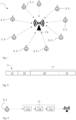
- FIG. 1 shows an exemplary embodiment of a wireless data transmission system 1 operating on an LPWAN protocol.
- the system 1 comprises a plurality of smart meters 3 each comprising a transmitter 5 and a single base station 7 comprising a receiver 9.
- the transmitters 5 and the receiver 9 are not shown as individual components in the figures. However, it is understood that each transmitter and each receiver comprise at least one antenna, receive and/or transmit circuitry and at least one processor for encoding or decoding data.
- the LPWAN protocol as shown in Figure 1 only uses unidirectional communication from the transmitters 5 to the receiver 9 but not in the opposite direction. However, all devices 3, 7 may also include transceivers and the system 1 may allow bidirectional communication between the smart meters 3 and the base station 7.
- the smart meters 3 transmit measurement results to the base station 7 at regular or irregular intervals. Since the smart meters 3 in the exemplary embodiment are battery powered, the power available for wireless data transmission is limited. Note that the batteries are not shown in the figures. The limitation is not only caused by the fact that the battery needs to keep the device operation for timespans ranging between 10 years and 20 years and conserving power is critical for such batteries, but also by the fact that only a very limited current can be drained from these batteries. Due to limited current directly available from the battery, the smart meters 3 comprise additional capacitors which provide the power required for data transmission to the base station 7. High-quality capacitors are expensive. Therefore, keeping the power required for data transmissions low also benefits the production costs of the smart meters 3.
- One straightforward way of limiting the power required for sending a transmission is the reduction of the on-air time, i.e., the time it takes to send out a message. Reducing the on-air time can, in particular, be achieved by reducing the number of bits that are transmitted with every packet.
- the packet 11 comprises a synchronization section 13, a header 15 and a payload section 17.
- the bits of the synchronization section 13 allow the transmitter to detect that a packet is being received and enable the receiving of the subsequent information.
- the header section 15 includes information that is deemed essential for processing the packet 11, but none of that information is related to the measurement results that shall be transmitted from the smart meter 3 to the base station 7. This information is entirely included in the payload section 17 which additional carries error correction information.
- One straightforward way of reducing the length of a packet 11 and thereby the on-air time is to remove information from the packet's header or header section 15 that is not essential for successfully decoding the packet 11.
- Another way of reducing the on-air time is the implementation of incremental redundancy, where a payload encoded for forward error correction at the transmitter 5 is split into multiple packets 11a, 11b, 11c, i.e., the packets 11a, 11b, 11c form a multi-burst or multi-packet transmission 12 as shown schematically in Figure 3 .
- the bits for each of the packets 11a, 11b, 11c are selected from the payload bits encoded at the transmitters so that the payload can be obtained at the receiver? using forward error correction decoding from each of the packets 11a, 11b, 11c independently.
- one or more received packets 11a, 11b, 1 1c can be combined to increase the amount of redundant information available for forward error correction.
- Using incremental redundancy reduces the on-air time required for each individual packet 11a, 11b, 11c as compared to a single packet including all payload and error correction bits. Therefore, smaller capacitors at the transmitter 5 in the smart meter 3 can be used as less energy is required per transmission.
- the header of each packet 11a, 11b, 11c of a multi-packet transmission comprises an identifier allowing a receiver 9 of a packet of the multi-packet transmission to identify which packet 11a, 11b, 11c in the sequence of packets 11a, 11b, 11c has been received.
- This identifier is not included in the header 15 of the packets 11 in the exemplary embodiments.
- the fast-decoding method implemented by the receiver 9 does not require a packet identifier in the header. By shortening the header, the overall length of the packet 11 and thus the on-air time can be reduced, thereby reducing the power consumption at the transmitter 5 in the battery-powered smart meter 3.
- the method could also be implemented if the header would include a packet identifier.
- FIG. 1 Another benefit of reducing the on-air time is achieved at the receiver 9.
- nine smart meters 3 are transmitting packets 11 with measurements results to the base station 7.
- several hundred or several thousand smart meters 3 will be associated with a single base station 7. Since none of the smart meters 3 is aware of any of the other smart meters 3, the transmissions of the smart meters 3 are not coordinated, the transmission medium at the receiver9 may be congested and transmissions from different transmitters 5 can collide. Reducing the transmission time of each packet 11, i.e., the time each packet 11 occupies the transmission medium reduces the risk of collisions and increases the chances that the payload of a packet can be decoded successfully.
- the payload 19 comprises in total M bits made up from data bits and integrity check bits.
- the data bits carry information such as measurement data that shall be sent from the transmitter 5 to the receiver 9, whereas the integrity check bits are included in the payload to verify whether the payload 19 has been correctly decoded at the receiver 9.
- the payload 19 has 14 bits: 10111100010011.
- the payload 19 comprises 14 bytes: BC4D789AF135E26BC4D789AF135E.
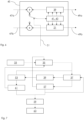
- the payload 19 of M bits is encoded using L convolutional encoders 21a, 21b, ..., 21n.
- Each of the L convolutional encoders employs a different polynomial or encoder transfer function H ( z ) .
- four convolutional encoders are used for encoding the payload 19.
- he first encoder transfer function is the unity function, i.e., the encoded bits are identical to the unencoded bits.
- the combined output of all L convolutional encoders 21a, 21b, ..., 21n is subsequently referred to as the set S of encoder output bits 23.
- the set of encoder output bits comprises L. M bits. From the set of encoders bits, subsets S 1 , S 2 , ..., S n of encoder output bits 25a, ..., 25m are selected for the N packets 11 to be transmitted according to packet-specific puncturing patterns 27a, ..., 27m.
- each of the packets 11a, 11b, 11c of the first exemplary embodiment comprises 16 bits: 14 bits are selected to represent the information contained in the payload 19, whereas the remaining two bits are redundant bits carrying redundant information that is intended to be used for forward error correction at the receiver 9.
- each of the packets 11a, 11b, 11c of the second exemplary embodiment comprises 16 bytes. 14 bytes carry the information of the payload 19 and two bytes carry redundant information intended for forward error correction. In Figure 2 this is shown by the dashed line separating the payload section 17 of the packet 11 into a non-redundant section 29 carrying the non-redundant bits and a redundant section 31 carrying the additional redundant bits for forward error correction.
- the packet-specific puncturing patterns 27a, ..., 27m of the first and second exemplary embodiment are configured in a similar way for selecting encoder output bits from different convolutional encoders 21a, 21b, ..., 21n.
- the first puncturing pattern 21a is configured for selecting all encoder output bits obtained using the first convolutional encoder 21a as the bits representing the payload 19. Further, the 7 th and 14 th bit are selected from the output of the fourth convolutional encoder.
- all encoder output bits from the second convolutional encoder 21b and the 6 th and 13 th bit are selected from the fourth convolutional encode.
- the third subset 25c all encoder output bits from the third convolutional encoder 21b and the 5 th and 12 th bit are selected from the fourth convolutional encoder.
- S 1 BC4D789AF135E26BC4D789AF135EA6A0
- S 2 DF074536E0283620B8CA9D7493FE2489
- S 3 FD3CEDA018121F97B98B2C7155AA4B99 .
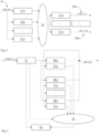
- Figure 5 is a flow chart schematically depicting how the received bits of a packet are decoded
- Figure 7 outlines the steps performed according to the exemplary embodiment of the method.
- the receiver 9 After receiving a packet 11 of the multi-packet transmission at a receiver 9, the receiver 9 first processes the synchronization section 13 and the header 15 in a well-known manner which is not described in any more detail here. However, it is noted that the receiver 9 does not obtain any indication from the header 15 of the packet 11 as which packet 11 in the multi-packet transmission 12 has been received, i.e., the receiver 9 does not positively know which packet 11 of the sequence of packets 11 has been received.
- the receiver 9 determines the bit error rate (BER) of the header 15 and the synchronization section 13 of the received packet. If the BER exceeds a predetermined threshold, the receiver 9 determines that it is unlikely that forward error decoding the packet 11 alone without the additional redundant information from the other packets 11 of the multi-burst transmission 12 will be successful. In this case, the processing of the packet 11 alone is terminated and it is stored for further combined forward error decoding with other packets of the multi-packet transmission 12. In case the BER is below the threshold, the method moved to the second step 35.
- BER bit error rate
- a packet-specific puncturing pattern is selected at the receiver 9 which could have been used to select the received encoder output bits at the transmitter 5.
- the receiver 9 commences with the puncturing pattern applied for the first packet 11a in the multi-burst transmission 12. If the receiver 9 is aware of other packets 11 from the same multi-burst transmission, the receiver 9 aims to infer from the previously received packets 11 which puncturing pattern may have been used for the current packet 11. For example, the receiver 9 may have been able to establish for a previously received packet the correct puncturing pattern but failed to decode the packet 11 due to transmission errors. In that case, the receiver 9 can conclude which puncturing pattern must have been used for the current packet 11.
- the receiver 9 next tries decoding the received encoder output bits using convolutional encoders 39a, 39b, ..., 39n with inverse polynomials compared to the convolutional encoders 21a, 21b, ..., 21n used at the transmitter 5 for encoding the payload 19.
- convolutional encoders 39a, 39b, ..., 39n with inverse polynomials compared to the convolutional encoders 21a, 21b, ..., 21n used at the transmitter 5 for encoding the payload 19.
- the inverse convolutional encoders 39a, 39b, ..., 39n can be used to retrieve the original payload with a minimum of computational effort.
- each received bit is processed individually.
- a puncturing unit 41 at the receiver establishes for each bit from which of the L convolutional encoders 21a, 21b, ..., 21n had been used to obtain the respective bit (provided that the correct packet-specific puncturing pattern has been selected) and whether the respective bit is a non-redundant bit or a redundant bit.
- the receiver 9 comprises for every inverse convolutional encoder 39a, 39b, ..., 39n with the encoder transfer function H -1 ( z ) the corresponding non-inverted convolutional encoder 21a, 21b, ..., 21n with the encoder transfer function H ( z ).
- every inverse convolutional encoder 39 at the receiver 9 shares it state 41 with a corresponding non-inverted convolutional encoder 21.
- the state 41 is in the exemplary embodiment formed by a tapped delay line 43.
- the conceptual combination of the convolutional encoder 21 and the inverse convolutional encoder39 with the shared state 41 is subsequently referred to as a bidirectional encoder 45.
- the bidirectional encoder 45 has two inputs and two outputs: a first input 47a for encoded bits, a second input 47b for decoded bits, a first output 49a for decoded bits, and a second output 49b for encoded bits.
- a control line 51 is provided for switching between the first input 47a and the second input 47b.
- the control line 51 activates the first input 47a.
- the received bit is propagated through the inverse convolution encoder 39 and the state 41 of the both the inverse convolutional encoder 39 and non-inverted convolutional encoder 21 are updated.
- the decoded bit is obtained at the corresponding first output 49a.
- the status of all other convolutional decoders 39b, ..., 39n is updated in the fifth step 53 by propagating the decoded bit through the non-inverted convolutional decoders 21b, ..., 21n.
- the just decoded bit is sent to the respective inputs 47b for decoded bits and the control line 51 is set so that the bidirectional encoder 45 processes decoded bits.
- the respective encoded bits are obtained and stored collectively as encoder output bits 55.
- the receiver 39 returns to the third step 37 for processing the next received bit by determining based on the selected puncturing pattern whether the next bit is redundant and which encoder 21a, 21b, ..., 21n supposedly produced the respective bit at the transmitter 5. If the subsequent bit carries non-redundant information, the previous processing steps are repeated. However, if the next received bit is a redundant bit, processing proceeds to the sixth step 57.
- the sixth step 57 it is determined whether the received redundant bit can be obtained from the decoded bits at the receiver 9. For example, if the received redundant bit was according to the selected puncturing pattern obtained by encoding the first seven payload bits at the fourth convolutional encoder, the same redundant bit should be obtained from the fourth non-inverted convolutional encoder 21 when encoding the seventh decoded bit.
- the comparison is performed in Figure 5 using a compare unit 56.
- the likelihood of having selected the correct puncturing pattern is > 99%.
- a received redundant bit does not match the redundant bit obtained from the decoded payload bits, a new puncturing pattern can be selected, i.e., the method moves to the second step 35. If all puncturing patterns have been tried or if it has been determined at an earlier stage that the correct puncturing pattern was used, the receiver9 tries decoding the packet 11 using forward error correction decoding in a seventh step 59.
- the redundant bit is, for example, transmitted as one of the last bits in a packet 11 but from the puncturing pattern is known that the redundant bit was obtained by encoding only a few of the payload bits, the redundant bit can and should be processed as soon as all bits have been decoded that are required for establishing whether the redundant bit can be obtained from the decoded bits. In case a redundant bit cannot be successfully obtained from the decoded bits, fast decoding of the packet 11 without forward error decoding can be terminated early to preserve processing resources.
- an integrity check is performed using CRC bits that are included in the payload 19. If the integrity check is successful, it is concluded that the payload has been successfully decoded, processing of all other packets 11 of the same multi-packet transmission 12 is halted, and the remaining packets 11 are discarded.
- forward error correction decoding is performed according to the seventh step 59. If forward error correction decoding also fails, the packet is stored in a nineth step 63 for further combination with other packets 11 to implement the established concept of incremental redundancy.
Landscapes
- Engineering & Computer Science (AREA)
- Physics & Mathematics (AREA)
- Probability & Statistics with Applications (AREA)
- Theoretical Computer Science (AREA)
- Computer Networks & Wireless Communication (AREA)
- Signal Processing (AREA)
- Mathematical Physics (AREA)
- Detection And Prevention Of Errors In Transmission (AREA)
Priority Applications (1)
| Application Number | Priority Date | Filing Date | Title |
|---|---|---|---|
| EP23214841.1A EP4568148A1 (de) | 2023-12-07 | 2023-12-07 | Verfahren, empfänger und system zur schnellen decodierung einer drahtlosen übertragung mit mehreren paketen |
Applications Claiming Priority (1)
| Application Number | Priority Date | Filing Date | Title |
|---|---|---|---|
| EP23214841.1A EP4568148A1 (de) | 2023-12-07 | 2023-12-07 | Verfahren, empfänger und system zur schnellen decodierung einer drahtlosen übertragung mit mehreren paketen |
Publications (1)
| Publication Number | Publication Date |
|---|---|
| EP4568148A1 true EP4568148A1 (de) | 2025-06-11 |
Family
ID=89121707
Family Applications (1)
| Application Number | Title | Priority Date | Filing Date |
|---|---|---|---|
| EP23214841.1A Pending EP4568148A1 (de) | 2023-12-07 | 2023-12-07 | Verfahren, empfänger und system zur schnellen decodierung einer drahtlosen übertragung mit mehreren paketen |
Country Status (1)
| Country | Link |
|---|---|
| EP (1) | EP4568148A1 (de) |
Citations (3)
| Publication number | Priority date | Publication date | Assignee | Title |
|---|---|---|---|---|
| EP2924907A1 (de) | 2010-07-15 | 2015-09-30 | Fraunhofer-Gesellschaft zur Förderung der angewandten Forschung e.V. | Konzept zur kombination codierter datenpakete mit robustem headerschutz |
| WO2016161843A1 (en) * | 2015-04-10 | 2016-10-13 | Huawei Technologies Co., Ltd. | System and method for duplicating preamble information |
| US20200287660A1 (en) * | 2019-03-06 | 2020-09-10 | Jung Hoon SUH | Bcc puncturing patterns for data retransmission in wireless network |
-
2023
- 2023-12-07 EP EP23214841.1A patent/EP4568148A1/de active Pending
Patent Citations (3)
| Publication number | Priority date | Publication date | Assignee | Title |
|---|---|---|---|---|
| EP2924907A1 (de) | 2010-07-15 | 2015-09-30 | Fraunhofer-Gesellschaft zur Förderung der angewandten Forschung e.V. | Konzept zur kombination codierter datenpakete mit robustem headerschutz |
| WO2016161843A1 (en) * | 2015-04-10 | 2016-10-13 | Huawei Technologies Co., Ltd. | System and method for duplicating preamble information |
| US20200287660A1 (en) * | 2019-03-06 | 2020-09-10 | Jung Hoon SUH | Bcc puncturing patterns for data retransmission in wireless network |
Similar Documents
| Publication | Publication Date | Title |
|---|---|---|
| CN1853380B (zh) | 有效的自动重复请求的方法和装置 | |
| US10084569B2 (en) | Data sending method and apparatus | |
| EP2540024B1 (de) | System und verfahren zum senden und empfangen von bestätigungsinformationen | |
| CN101136722B (zh) | 一种适用于高速移动终端的数据发送方法及传输设备 | |
| EP2924907B1 (de) | Konzept zur kombination codierter datenpakete mit robustem headerschutz | |
| US10516505B2 (en) | Baseband processors, base station, user device, and methods thereof | |
| EP1154576A2 (de) | Fehlerdetektion für ARQ Systeme | |
| RU2531264C2 (ru) | Способ кодирования информации обратной связи harq с помощью двух отдельных кодовых слоев с неравной защитой от ошибок для dtх и ack/nack | |
| CN109889308B (zh) | 物联网中联合极化编译码的混合自动重传请求方法 | |
| US11088780B2 (en) | Low complexity blind detection of code rate | |
| WO2009015170A1 (en) | Hybrid automatic repeat request (harq) systems and methods for packet-based networks | |
| US10700816B2 (en) | Method for performing HARQ using polar code | |
| JP2007043550A (ja) | 通信方法および通信システム | |
| US7797604B2 (en) | Codeword automatic repeat request/decoding method and transmission/reception apparatus using feedback information | |
| JP4509383B2 (ja) | 組み合わせハイブリッド自動再送信要求手法 | |
| CN109639397B (zh) | 一种复合信道下极化码的混合自动重传请求方法 | |
| RU2462822C2 (ru) | Способ подтверждения приема данных | |
| US10819472B2 (en) | Method for performing HARQ by using polar code having random length | |
| CN103414543B (zh) | 一种调整harq缓存量的方法及终端 | |
| Dong et al. | CARE: Corruption-aware retransmission with adaptive coding for the low-power wireless | |
| EP3526916B1 (de) | Datencodierung und -decodierung | |
| EP4568148A1 (de) | Verfahren, empfänger und system zur schnellen decodierung einer drahtlosen übertragung mit mehreren paketen | |
| CN113366785A (zh) | 用于重传mac协议数据单元(mpdu)的通信发射器 | |
| Chan et al. | Adaptive type II hybrid ARQ scheme using zigzag code | |
| Wu et al. | ACR: Active collision recovery in dense wireless sensor networks |
Legal Events
| Date | Code | Title | Description |
|---|---|---|---|
| PUAI | Public reference made under article 153(3) epc to a published international application that has entered the european phase |
Free format text: ORIGINAL CODE: 0009012 |
|
| STAA | Information on the status of an ep patent application or granted ep patent |
Free format text: STATUS: THE APPLICATION HAS BEEN PUBLISHED |
|
| AK | Designated contracting states |
Kind code of ref document: A1 Designated state(s): AL AT BE BG CH CY CZ DE DK EE ES FI FR GB GR HR HU IE IS IT LI LT LU LV MC ME MK MT NL NO PL PT RO RS SE SI SK SM TR |
|
| STAA | Information on the status of an ep patent application or granted ep patent |
Free format text: STATUS: REQUEST FOR EXAMINATION WAS MADE |
|
| 17P | Request for examination filed |
Effective date: 20251106 |
|
| GRAP | Despatch of communication of intention to grant a patent |
Free format text: ORIGINAL CODE: EPIDOSNIGR1 |
|
| STAA | Information on the status of an ep patent application or granted ep patent |
Free format text: STATUS: GRANT OF PATENT IS INTENDED |
|
| RIC1 | Information provided on ipc code assigned before grant |
Ipc: H04L 1/00 20060101AFI20260206BHEP Ipc: H03M 13/23 20060101ALI20260206BHEP Ipc: H03M 13/00 20060101ALI20260206BHEP |
|
| INTG | Intention to grant announced |
Effective date: 20260316 |