EP4568064A2 - Unterbrechungsfreie stromversorgungssysteme und verfahren zur unterstützung von hocheffizientem bypass-betrieb mit einer stromquelle mit variabler verfügbarkeit - Google Patents
Unterbrechungsfreie stromversorgungssysteme und verfahren zur unterstützung von hocheffizientem bypass-betrieb mit einer stromquelle mit variabler verfügbarkeit Download PDFInfo
- Publication number
- EP4568064A2 EP4568064A2 EP25172191.6A EP25172191A EP4568064A2 EP 4568064 A2 EP4568064 A2 EP 4568064A2 EP 25172191 A EP25172191 A EP 25172191A EP 4568064 A2 EP4568064 A2 EP 4568064A2
- Authority
- EP
- European Patent Office
- Prior art keywords
- power
- power source
- converter
- coupled
- power conversion
- Prior art date
- Legal status (The legal status is an assumption and is not a legal conclusion. Google has not performed a legal analysis and makes no representation as to the accuracy of the status listed.)
- Pending
Links
Images



Classifications
-
- H—ELECTRICITY
- H02—GENERATION; CONVERSION OR DISTRIBUTION OF ELECTRIC POWER
- H02J—ELECTRIC POWER NETWORKS; CIRCUIT ARRANGEMENTS OR SYSTEMS FOR SUPPLYING OR DISTRIBUTING ELECTRIC POWER; SYSTEMS FOR STORING ELECTRIC ENERGY
- H02J9/00—Circuit arrangements for emergency or stand-by power supply, e.g. for emergency lighting
- H02J9/04—Circuit arrangements for emergency or stand-by power supply, e.g. for emergency lighting in which the distribution system is disconnected from the normal source and connected to a standby source
-
- H—ELECTRICITY
- H02—GENERATION; CONVERSION OR DISTRIBUTION OF ELECTRIC POWER
- H02J—ELECTRIC POWER NETWORKS; CIRCUIT ARRANGEMENTS OR SYSTEMS FOR SUPPLYING OR DISTRIBUTING ELECTRIC POWER; SYSTEMS FOR STORING ELECTRIC ENERGY
- H02J3/00—Circuit arrangements for AC mains or AC distribution networks
- H02J3/38—Arrangements for feeding a single network from two or more generators or sources in parallel; Arrangements for feeding already energised networks from additional generators or sources in parallel
- H02J3/381—Dispersed generators
-
- H—ELECTRICITY
- H02—GENERATION; CONVERSION OR DISTRIBUTION OF ELECTRIC POWER
- H02J—ELECTRIC POWER NETWORKS; CIRCUIT ARRANGEMENTS OR SYSTEMS FOR SUPPLYING OR DISTRIBUTING ELECTRIC POWER; SYSTEMS FOR STORING ELECTRIC ENERGY
- H02J9/00—Circuit arrangements for emergency or stand-by power supply, e.g. for emergency lighting
- H02J9/04—Circuit arrangements for emergency or stand-by power supply, e.g. for emergency lighting in which the distribution system is disconnected from the normal source and connected to a standby source
- H02J9/06—Circuit arrangements for emergency or stand-by power supply, e.g. for emergency lighting in which the distribution system is disconnected from the normal source and connected to a standby source with automatic change-over, e.g. UPS systems
- H02J9/062—Circuit arrangements for emergency or stand-by power supply, e.g. for emergency lighting in which the distribution system is disconnected from the normal source and connected to a standby source with automatic change-over, e.g. UPS systems for AC powered loads
-
- H—ELECTRICITY
- H02—GENERATION; CONVERSION OR DISTRIBUTION OF ELECTRIC POWER
- H02J—ELECTRIC POWER NETWORKS; CIRCUIT ARRANGEMENTS OR SYSTEMS FOR SUPPLYING OR DISTRIBUTING ELECTRIC POWER; SYSTEMS FOR STORING ELECTRIC ENERGY
- H02J2101/00—Supply or distribution of decentralised, dispersed or local electric power generation
- H02J2101/20—Dispersed power generation using renewable energy sources
- H02J2101/22—Solar energy
- H02J2101/24—Photovoltaics
-
- H—ELECTRICITY
- H02—GENERATION; CONVERSION OR DISTRIBUTION OF ELECTRIC POWER
- H02J—ELECTRIC POWER NETWORKS; CIRCUIT ARRANGEMENTS OR SYSTEMS FOR SUPPLYING OR DISTRIBUTING ELECTRIC POWER; SYSTEMS FOR STORING ELECTRIC ENERGY
- H02J2101/00—Supply or distribution of decentralised, dispersed or local electric power generation
- H02J2101/20—Dispersed power generation using renewable energy sources
- H02J2101/28—Wind energy
-
- H—ELECTRICITY
- H02—GENERATION; CONVERSION OR DISTRIBUTION OF ELECTRIC POWER
- H02J—ELECTRIC POWER NETWORKS; CIRCUIT ARRANGEMENTS OR SYSTEMS FOR SUPPLYING OR DISTRIBUTING ELECTRIC POWER; SYSTEMS FOR STORING ELECTRIC ENERGY
- H02J2105/00—Networks for supplying or distributing electric power characterised by their spatial reach or by the load
- H02J2105/40—Networks for supplying or distributing electric power characterised by their spatial reach or by the load characterised by the loads connecting to the networks or being supplied by the networks
- H02J2105/42—Home appliances
- H02J2105/425—Home appliances the loads being an Information and Communication Technology [ICT] facility
-
- Y—GENERAL TAGGING OF NEW TECHNOLOGICAL DEVELOPMENTS; GENERAL TAGGING OF CROSS-SECTIONAL TECHNOLOGIES SPANNING OVER SEVERAL SECTIONS OF THE IPC; TECHNICAL SUBJECTS COVERED BY FORMER USPC CROSS-REFERENCE ART COLLECTIONS [XRACs] AND DIGESTS
- Y02—TECHNOLOGIES OR APPLICATIONS FOR MITIGATION OR ADAPTATION AGAINST CLIMATE CHANGE
- Y02B—CLIMATE CHANGE MITIGATION TECHNOLOGIES RELATED TO BUILDINGS, e.g. HOUSING, HOUSE APPLIANCES OR RELATED END-USER APPLICATIONS
- Y02B10/00—Integration of renewable energy sources in buildings
- Y02B10/70—Hybrid systems, e.g. uninterruptible or back-up power supplies integrating renewable energies
-
- Y—GENERAL TAGGING OF NEW TECHNOLOGICAL DEVELOPMENTS; GENERAL TAGGING OF CROSS-SECTIONAL TECHNOLOGIES SPANNING OVER SEVERAL SECTIONS OF THE IPC; TECHNICAL SUBJECTS COVERED BY FORMER USPC CROSS-REFERENCE ART COLLECTIONS [XRACs] AND DIGESTS
- Y02—TECHNOLOGIES OR APPLICATIONS FOR MITIGATION OR ADAPTATION AGAINST CLIMATE CHANGE
- Y02E—REDUCTION OF GREENHOUSE GAS [GHG] EMISSIONS, RELATED TO ENERGY GENERATION, TRANSMISSION OR DISTRIBUTION
- Y02E10/00—Energy generation through renewable energy sources
- Y02E10/50—Photovoltaic [PV] energy
- Y02E10/56—Power conversion systems, e.g. maximum power point trackers
-
- Y—GENERAL TAGGING OF NEW TECHNOLOGICAL DEVELOPMENTS; GENERAL TAGGING OF CROSS-SECTIONAL TECHNOLOGIES SPANNING OVER SEVERAL SECTIONS OF THE IPC; TECHNICAL SUBJECTS COVERED BY FORMER USPC CROSS-REFERENCE ART COLLECTIONS [XRACs] AND DIGESTS
- Y02—TECHNOLOGIES OR APPLICATIONS FOR MITIGATION OR ADAPTATION AGAINST CLIMATE CHANGE
- Y02P—CLIMATE CHANGE MITIGATION TECHNOLOGIES IN THE PRODUCTION OR PROCESSING OF GOODS
- Y02P80/00—Climate change mitigation technologies for sector-wide applications
- Y02P80/10—Efficient use of energy, e.g. using compressed air or pressurized fluid as energy carrier
Definitions
- the inventive subject matter relates to power supply systems and methods and, more particularly, to uninterruptible power supply (UPS) systems and methods.
- UPS uninterruptible power supply
- UPS systems are commonly used in installations such as data centers, medical centers and industrial facilities. UPS systems may be used in such installations to provide backup power to maintain operation in event of failure of the primary utility supply.
- UPS systems common have an "on-line" configuration including a rectifier and inverter coupled by a DC link that is also coupled to an auxiliary power source, such as a battery, fuel cell or other energy storage device.
- a variably available renewable source such as a photovoltaic source, may be coupled to the DC link of an on-line UPS to provide supplemental power, as described, for example, in U.S. Patent No. 7,411,308 to Parmley and an article entitled " Photovoltaic UPS” by Jayasimha et al., IEEE TENCON 2003 Conference on Convergent Technologies for Asia- Pacific Region, vol. 4, pp. 1419-1423 (2003 ).
- on-line UPSs that are used in such applications may support an "efficiency" mode in which the rectifier/inverter conversion chain is bypassed using a static switch when the utility source is within nominally acceptable bounds.
- UPS uninterruptible power supply
- the UPS system further includes a control circuit operatively associated with the power conversion circuit and the switching circuit and configured to cause concurrent transfer of power to a load at the AC output from the AC power source and the variably available power source via the switching circuit and the power conversion circuit, respectively.
- the DC link is configured to receive power from an auxiliary power source and the control circuit is configured to support a mode of operation in which the power conversion circuit provides power to the load from the auxiliary power source responsive to a status of the AC power source.
- the power conversion circuit includes a first power conversion circuit
- the UPS system further includes a second power conversion circuit operatively controlled by the control circuit and including an AC/DC converter coupled to the AC input, a DC/AC converter coupled to the AC output and a DC link coupling the AC/DC converter to the DC/AC converter.
- the switching circuit may include a bypass circuit.
- the control circuit may support a mode in which power is concurrently transferred to the load from the AC power source and the variably available power source via the bypass circuit and the first power conversion circuit, respectively, and a mode in which power is concurrently transferred to the load from the variably available power source and an auxiliary power source coupled to the DC link of the first power conversion circuit.
- the control circuit may further support a mode in which power is concurrently transferred to the load from the AC power source and the variably available power source via the second power conversion circuit and the first power conversion circuit, respectively.
- the DC links of the first and second power conversion circuits are configured to receive power from respective auxiliary power sources, and the control circuit supports a mode in which power is concurrently transferred to the load from the variably available power source and from the auxiliary power sources.
- first and second power conversion circuits are included in respective first and second power conversion modules, each of which includes a converter unit flexibly configurable to operate as a rectifier and a DC/DC converter.
- the converter unit of the first power conversion circuit is configured to operate as a DC/DC converter.
- Some embodiments of the inventive subject matter provide methods of operating a UPS system including an AC input configured to be coupled to an AC power source, an AC output configured to be coupled to a load, a power conversion circuit including a first converter configured to receive power from a variably available power source, a second converter coupled to the AC output, a DC link coupling the first and second converter circuits, a switching circuit configured to selectively couple and decouple the AC input and the AC output and a control circuit operatively associated with the power conversion circuit and the switching circuit.
- the methods include concurrently transferring power to a load at the AC output from the AC power source and the variably available power source via the switching circuit and the power conversion circuit, respectively.
- the DC link may be configured to receive power from an auxiliary power source and the methods may further include providing power to the load from the auxiliary power source via the power conversion responsive to a status of the AC power source.
- the power conversion circuit may includes first power conversion circuit, the UPS system may further include a second power conversion circuit operatively controlled by the control circuit and including an AC/DC converter coupled to the AC input, a DC/AC converter coupled to the AC output and a DC link coupling the AC/DC converter to the DC/AC converter.
- the switching circuit may include a bypass circuit.
- Methods may further include concurrently transferring power to the load from the AC power source and the variably available power source via the bypass circuit and the first power conversion circuit, respectively, and concurrently transferring power to the load from the variably available power source and an auxiliary power source coupled to the DC link of the first power conversion circuit.
- Methods may further include concurrently transferring power to the load from the AC power source and the variably available power source via the second power conversion circuit and the first power conversion circuit, respectively.
- the DC links of the first and second power conversion circuits may be configured to receive power from respective auxiliary power sources, and methods may further include concurrently transferring power to the load from the variably available power source and from the auxiliary power sources.
- the first and second power conversion circuits may be included in respective first and second power conversion modules, each of which includes a converter unit configurable to operate as a rectifier and a DC/DC converter.
- the converter unit of the first power conversion circuit may be operated as DC/DC converter.
- inventive subject matter may be embodied as systems, methods and computer program products. Some embodiments of the inventive subject matter may include hardware and/or combinations of hardware and software. Some embodiments of the inventive subject matter include circuitry configured to provide functions described herein. It will be appreciated that such circuitry may include analog circuits, digital circuits, and combinations of analog and digital circuits.
- the functions/acts noted in the figures may occur out of the order noted in the block diagrams and/or operational illustrations.
- two operations shown as occurring in succession may, in fact, be executed substantially concurrently or the operations may sometimes be executed in the reverse order, depending upon the functionality/acts involved.
- variable power sources include power sources, such as solar, wind, tidal and similar renewable energy sources, having an availability (presence and/or capacity) that fluctuates with environmental conditions (e.g., availability of wind, sun or tidal change) and that are not, as a general rule, available on demand.
- power sources may also be referred to as “variable”, “intermittent” or “non-dispatchable” and, for purposes of the present application, such sources shall be referred to as “variably available power sources.”
- FIG. 1 illustrates a UPS system 100 according to some embodiments of the inventive subject matter.
- the UPS system 100 includes an AC input 101 configured to be coupled to an AC power source 10 and an AC output 102 configured to be coupled to a load 20.
- the AC power source 10 may be single or multiphase and may comprise, for example, a utility source and/or a local source, such as a generator.
- the load 20 may comprise, in general, one load or an aggregation of single and/or multiphase loads, such as a collection of three-phase and single phase loads that may be found in a typical data center or similar facility.
- the UPS system 100 includes a first power conversion circuit 110 including a first converter circuit 112 configured to receive power from a variably available power source 30, a second converter circuit 114 coupled to the AC output 102, and a DC link 115 coupling the first and second converter circuits 112, 114.
- the first converter circuit 112 may operate as an AC/DC converter (a rectifier) or as a DC/DC converter.
- the UPS system 100 also includes a second power conversion circuit 120 that is configured to operate as an on-line UPS.
- the second power conversion circuit 120 includes an AC/DC converter circuit 122 coupled to a DC/DC converter circuit 124 by a DC link 125.
- An auxiliary power source 40 (e.g., one or more batteries) is coupled to the DC link 125, and may supply backup power in the event of a failure of the AC power source 10.
- An additional auxiliary power source 40 may be coupled to the DC link 115 of the first power conversion circuit 110.
- the UPS system 100 further includes a switching circuit, here shown as a bypass circuit 150 configured to selectively bypass the second conversion circuit 120 by selectively coupling and decoupling the AC input 101 and the AC output 102.
- a control circuit 160 is operatively associated with the first power conversion circuit 110, the second power conversion circuit 120 and the bypass circuit 150 and configured to cause concurrent transfer of power to the load 20 from the AC power source 10 and the variably available power source 30 via the bypass circuit 150 and the first power conversion circuit 110, respectively.
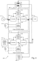
- FIG. 2 illustrates a modular UPS system 200 according to further embodiments that may provide such functionality.
- the UPS system 200 includes first and second power conversion modules 210, 220 having a common architecture, including first and second converter units 212, 214 linked by a DC bus 215, a battery interface unit 216 for coupling a battery to the DC bus 215 and a module control unit 218.
- the module control units 218 may be operatively associated with a system control circuit 240 that, for example, defines interoperation of the power conversion modules 210, 220 in various operating modes as described below.
- the modules 210, 220 may have the same or different form factors and/or capacities.
- the modules 210, 220 may have a common form factor and/or external connection configuration, and may be designed to be interchangeably installed in a system chassis.
- the second power conversion module 220 is configured to provide on-line UPS operation, with power being selectively supplied to a load 20 from an AC power source 10 and one or more backup batteries 40.
- the first power conversion module 210 is configured to provide an interface for a variably available power source 30 such as a photovoltaic source or wind power generator.
- the first converter unit 212 of the first power conversion module 210 may be configured to provide an appropriate conversion depending on the nature of the variably available power source 30, which may be different from a conversion provided by the first converter unit 212 of the first power conversion circuit 210.
- the first converter units 212 of the first and second power conversion modules 210, 220 may comprise respective active bridge circuits that are selectively configurable to operate as a rectifier or a DC/DC converter depending on, for example, control signals applied thereto by the module control units 218.
- One or more additional backup batteries may be coupled to the battery interface unit 216 of the first power conversion module 210.
- the control circuits of the UPS system 100 may support a plurality of operating modes. For example, as illustrated in FIG. 3 , when the AC power source 10 is operating within normal limits such that the second power conversion module 220 may be bypassed, power may be concurrently delivered to the load 20 from the AC power source 10 and the variably available power source 30 via the bypass circuit 230 and the first power conversion module 210, respectively. In another mode illustrated in FIG. 4 , when the bypass circuit 230 is opened and on-line conversion is performed by the second power conversion module 220, power may be concurrently delivered to the load 20 from the AC power source 10 and the variably available power source 30 via the second power conversion module 220 and the first power conversion module 210, respectively. As illustrated in FIG. 3 , when the AC power source 10 is operating within normal limits such that the second power conversion module 220 may be bypassed, power may be concurrently delivered to the load 20 from the AC power source 10 and the variably available power source 30 via the bypass circuit 230 and the first power conversion module 210, respectively. In another mode illustrated in
- power may be delivered to the load 20 from the one or more batteries 40 coupled to the second power conversion module 220 and from the variably available power source 30 via the second power conversion module 220 and the first power conversion module 210, respectively. Additional power may be supplied by one or more batteries 40 coupled to the first power conversion module 210.
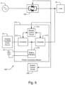
- FIG. 6 illustrates a UPS system 600 including a static switch 230 configured to couple and decouple an AC power source 10 to and from a load 20.
- a power conversion module 210 including components along the lines described above with reference to FIG. 2 is also coupled to the load 20 and is configured to transfer power from a variably available power source 30 to the load 20.
- One or more batteries 40 are coupled to the battery interface unit 216 of the power conversion module 210.
- the power conversion module 210 and the static switch 230 are cooperatively controlled by a system control circuit 240.
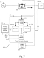
- FIG. 7 when the AC power source 10 is in a normal condition, power may be concurrently supplied from the AC power source 10 and the variably available power source 30 via the static switch 230 and the power conversion module 210, respectively.
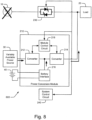
- FIG. 8 upon failure of the AC power source 10, power may be delivered to the load 20 from the variably available power source 30 and the one or more batteries 40 via the power conversion module 210.
Landscapes
- Engineering & Computer Science (AREA)
- Power Engineering (AREA)
- Business, Economics & Management (AREA)
- Emergency Management (AREA)
- Charge And Discharge Circuits For Batteries Or The Like (AREA)
- Supply And Distribution Of Alternating Current (AREA)
- Stand-By Power Supply Arrangements (AREA)
- Inverter Devices (AREA)
Applications Claiming Priority (3)
| Application Number | Priority Date | Filing Date | Title |
|---|---|---|---|
| US12/779,677 US8362647B2 (en) | 2010-05-13 | 2010-05-13 | Uninterruptible power supply systems and methods supporting high-efficiency bypassed operation with a variably available power source |
| EP11738795.1A EP2569846B8 (de) | 2010-05-13 | 2011-05-13 | Systeme und verfahren für unterbrechungsfreie stromversorgung zur unterstutzung hocheffizienter bypass-operationen mit einer stromquelle von variabler verfügbarkeit |
| PCT/IB2011/001024 WO2011141809A2 (en) | 2010-05-13 | 2011-05-13 | Uniterruptible power supply systems and methods supporting high-efficiency bypassed operation with a variably available power source |
Related Parent Applications (2)
| Application Number | Title | Priority Date | Filing Date |
|---|---|---|---|
| EP11738795.1A Division-Into EP2569846B8 (de) | 2010-05-13 | 2011-05-13 | Systeme und verfahren für unterbrechungsfreie stromversorgung zur unterstutzung hocheffizienter bypass-operationen mit einer stromquelle von variabler verfügbarkeit |
| EP11738795.1A Division EP2569846B8 (de) | 2010-05-13 | 2011-05-13 | Systeme und verfahren für unterbrechungsfreie stromversorgung zur unterstutzung hocheffizienter bypass-operationen mit einer stromquelle von variabler verfügbarkeit |
Publications (2)
| Publication Number | Publication Date |
|---|---|
| EP4568064A2 true EP4568064A2 (de) | 2025-06-11 |
| EP4568064A3 EP4568064A3 (de) | 2025-08-27 |
Family
ID=44629417
Family Applications (2)
| Application Number | Title | Priority Date | Filing Date |
|---|---|---|---|
| EP11738795.1A Active EP2569846B8 (de) | 2010-05-13 | 2011-05-13 | Systeme und verfahren für unterbrechungsfreie stromversorgung zur unterstutzung hocheffizienter bypass-operationen mit einer stromquelle von variabler verfügbarkeit |
| EP25172191.6A Pending EP4568064A3 (de) | 2010-05-13 | 2011-05-13 | Unterbrechungsfreie stromversorgungssysteme und verfahren zur unterstützung von hocheffizientem bypass-betrieb mit einer stromquelle mit variabler verfügbarkeit |
Family Applications Before (1)
| Application Number | Title | Priority Date | Filing Date |
|---|---|---|---|
| EP11738795.1A Active EP2569846B8 (de) | 2010-05-13 | 2011-05-13 | Systeme und verfahren für unterbrechungsfreie stromversorgung zur unterstutzung hocheffizienter bypass-operationen mit einer stromquelle von variabler verfügbarkeit |
Country Status (4)
| Country | Link |
|---|---|
| US (1) | US8362647B2 (de) |
| EP (2) | EP2569846B8 (de) |
| CN (1) | CN102893491B (de) |
| WO (1) | WO2011141809A2 (de) |
Families Citing this family (29)
| Publication number | Priority date | Publication date | Assignee | Title |
|---|---|---|---|---|
| US8373949B2 (en) * | 2010-06-16 | 2013-02-12 | Transocean Sedco Forex Ventures Limited | Hybrid power plant for improved efficiency and dynamic performance |
| US20120068541A1 (en) * | 2010-09-20 | 2012-03-22 | Eaton Corporation | Power supply systems and methods employing a ups interfaced generator |
| US9172271B2 (en) * | 2011-09-19 | 2015-10-27 | Schneider Electric It Corporation | Parallel control and protection for UPS |
| US20150318699A2 (en) * | 2011-09-29 | 2015-11-05 | James Frederick Wolter | Power generation system with integrated renewable energy generation, energy storage, and power control |
| US9425650B2 (en) * | 2012-01-31 | 2016-08-23 | General Electric Company | Systems, methods, and devices for control of multimode UPS |
| US9362781B2 (en) | 2012-09-14 | 2016-06-07 | Chloride Srl | Uninterruptible power supply system with fast transfer for undervoltage source line failures |
| US9806560B2 (en) * | 2012-10-04 | 2017-10-31 | Eaton Corporation | UPS with multiple independent static switches |
| US9647491B2 (en) * | 2013-07-08 | 2017-05-09 | Eaton Corporation | UPS systems and methods using variable configuration |
| US9431851B2 (en) | 2013-08-16 | 2016-08-30 | Eaton Corporation | UPS systems and methods using current-controlling low-loss modes |
| CN103683475A (zh) * | 2013-12-16 | 2014-03-26 | 广东志成冠军集团有限公司 | 一种大功率模块化ups电源 |
| US9735616B2 (en) * | 2014-03-13 | 2017-08-15 | General Electric Company | Systems and methods for providing increased fault current capability in uninterruptible power supply systems |
| CN103915886B (zh) * | 2014-03-31 | 2016-01-06 | 深圳市英威腾电源有限公司 | 不间断电源维护旁路装置及不间断电源系统 |
| GB2524992A (en) * | 2014-04-08 | 2015-10-14 | Eltek As | Electic multi-mode power converter module and power system |
| US10135292B2 (en) * | 2014-07-24 | 2018-11-20 | Neah Power Systems, Inc. | Method and system for simultaneously charging an energy storage device from multiple energy input devices |
| KR101626911B1 (ko) * | 2015-02-26 | 2016-06-02 | 연세대학교 산학협력단 | 복수개의 에너지 저장 장치를 위한 전력 제어 시스템 및 방법 |
| US9929567B2 (en) | 2015-08-26 | 2018-03-27 | Abb Schweiz Ag | Zero net energy DC datacenter power distribution architecture |
| CN105449829A (zh) * | 2015-12-21 | 2016-03-30 | 中国电子科技集团公司第十一研究所 | 一种电源保护电路 |
| US10931139B1 (en) | 2015-12-29 | 2021-02-23 | Signify Holding B.V. | Emergency battery packs for low voltage systems |
| US10424963B1 (en) * | 2016-02-18 | 2019-09-24 | Eaton Intelligent Power Limited | Methods and systems for charging a backup battery pack |
| US10103572B2 (en) * | 2016-04-27 | 2018-10-16 | Eaton Intelligent Power Limited | Uninterruptible power supply systems and methods using interconnected power routing units |
| US10374455B2 (en) | 2016-04-29 | 2019-08-06 | Hewlett Packard Enterprise Development Lp | Uninterruptible power supply including battery modules connected directly to direct current-alternating current inverter |
| KR102322366B1 (ko) * | 2017-03-02 | 2021-11-04 | 현대자동차주식회사 | 태양전지 시스템 및 그 제어 방법 |
| US10873206B2 (en) * | 2017-05-30 | 2020-12-22 | Schneider Electric It Corporation | System and method for power storage and distribution |
| WO2019040037A1 (en) * | 2017-08-21 | 2019-02-28 | General Electric Company | METHOD AND SYSTEM FOR CONTROLLING THE INTEGRATION OF A DIRECT CURRENT POWER SOURCE IN A HYBRID POWER GENERATION SYSTEM |
| US12095308B2 (en) | 2018-09-13 | 2024-09-17 | Ls Electric Co., Ltd. | Power supply device and power supply system |
| KR102299860B1 (ko) * | 2018-09-13 | 2021-09-09 | 엘에스일렉트릭 (주) | 전원 공급 장치 및 전원 공급 시스템 |
| DE102019210793A1 (de) * | 2019-07-22 | 2021-01-28 | Robert Bosch Gmbh | Elektrisches Energiespeichersystem und Verfahren zu dessen Betreiben |
| EP3772154A1 (de) * | 2019-07-31 | 2021-02-03 | ABB Schweiz AG | Ein stromversorgungssystem und eine unterbrechungsfreie stromversorgung mit dem stromversorgungssystem |
| CA3232790A1 (en) * | 2021-09-22 | 2023-03-30 | Flexgen Power Systems, Inc. | Electrical systems and methods using high capacity local bus supported by energy storage |
Citations (1)
| Publication number | Priority date | Publication date | Assignee | Title |
|---|---|---|---|---|
| US7411308B2 (en) | 2005-02-26 | 2008-08-12 | Parmley Daniel W | Renewable energy power systems |
Family Cites Families (21)
| Publication number | Priority date | Publication date | Assignee | Title |
|---|---|---|---|---|
| US5929538A (en) | 1997-06-27 | 1999-07-27 | Abacus Controls Inc. | Multimode power processor |
| US6134124A (en) | 1999-05-12 | 2000-10-17 | Abb Power T&D Company Inc. | Universal distributed-resource interface |
| US6847130B1 (en) | 2002-09-19 | 2005-01-25 | Metropolitan Industries, Inc. | Uninterruptible power system |
| EP1559179A4 (de) | 2002-10-22 | 2006-07-12 | Youtility Inc | Hybrider stromwandler mit generator mitvariabler geschwindigkeit bzw. ununterbrechbarer stromversorgung |
| US6921985B2 (en) | 2003-01-24 | 2005-07-26 | General Electric Company | Low voltage ride through for wind turbine generators |
| JP4071675B2 (ja) * | 2003-05-27 | 2008-04-02 | 東芝三菱電機産業システム株式会社 | 無停電電源装置の並列運転システム |
| CN102163872B (zh) | 2004-08-31 | 2013-02-06 | 美国能量变换公司 | 提供不间断电源的设备及其方法 |
| US20080217998A1 (en) | 2005-02-26 | 2008-09-11 | Parmley Daniel W | Renewable energy power systems |
| US7212421B2 (en) | 2005-03-15 | 2007-05-01 | Perfect Electric Power, Inc. | Combination feedback controller and power regulator using same |
| US7265458B2 (en) * | 2005-04-08 | 2007-09-04 | Eaton Power Quality Corporation | Apparatus and methods for coordinated static switch operations for load transfers in uninterruptible power supply systems |
| US7566988B2 (en) * | 2005-06-14 | 2009-07-28 | Liebert Corporation | Method and apparatus for monitoring UPS power sources |
| US20070076444A1 (en) | 2005-10-03 | 2007-04-05 | Mc Nulty Thomas C | Using a variable frequency drive for non-motor loads |
| EP2044326B1 (de) | 2006-07-06 | 2018-08-22 | Acciona Windpower, S.A. | Systeme, verfahren und vorrichtungen für eine windturbinensteuerung |
| US7652393B2 (en) | 2006-09-14 | 2010-01-26 | American Power Conversion Corporation | Apparatus and method for employing a DC source with an uninterruptible power supply |
| TWM317698U (en) * | 2006-10-17 | 2007-08-21 | Ming-Hsiang Yeh | Improved structure for electricity storage equipment |
| TWI332743B (en) * | 2006-11-30 | 2010-11-01 | Ind Tech Res Inst | Control device and method of renewable energy system signgle-phase power conditioner |
| CN101242104B (zh) | 2007-02-06 | 2011-05-04 | 鸿富锦精密工业(深圳)有限公司 | 具太阳能充电功能的不间断电源 |
| EP1965487A1 (de) | 2007-02-28 | 2008-09-03 | Gamesa Innovation & Technology, S.L. | An ein elektrisches Netz angeschlossene unterbrechungsfreie Stromversorgung |
| US20090009001A1 (en) * | 2007-07-05 | 2009-01-08 | Liebert Corporation | Method and apparatus for synchronization of actions in a parallel ups system using a serial communications bus |
| TW200915702A (en) * | 2007-09-19 | 2009-04-01 | Delta Electronics Inc | Uninterruptible power supply system and controlling method thereof |
| US20090284074A1 (en) | 2008-05-19 | 2009-11-19 | Ming-Hsiang Yeh | Inverter |
-
2010
- 2010-05-13 US US12/779,677 patent/US8362647B2/en active Active
-
2011
- 2011-05-13 EP EP11738795.1A patent/EP2569846B8/de active Active
- 2011-05-13 CN CN201180023779.3A patent/CN102893491B/zh active Active
- 2011-05-13 WO PCT/IB2011/001024 patent/WO2011141809A2/en not_active Ceased
- 2011-05-13 EP EP25172191.6A patent/EP4568064A3/de active Pending
Patent Citations (1)
| Publication number | Priority date | Publication date | Assignee | Title |
|---|---|---|---|---|
| US7411308B2 (en) | 2005-02-26 | 2008-08-12 | Parmley Daniel W | Renewable energy power systems |
Non-Patent Citations (1)
| Title |
|---|
| JAYASIMHA ET AL.: "Photovoltaic UPS", IEEE TENCON 2003 CONFERENCE ON CONVERGENT TECHNOLOGIES FOR ASIA-PACIFIC REGION, vol. 4, 2003, pages 1419 - 1423, XP010687653, DOI: 10.1109/TENCON.2003.1273152 |
Also Published As
| Publication number | Publication date |
|---|---|
| WO2011141809A3 (en) | 2012-08-23 |
| EP2569846B1 (de) | 2025-06-25 |
| US8362647B2 (en) | 2013-01-29 |
| EP2569846A2 (de) | 2013-03-20 |
| EP4568064A3 (de) | 2025-08-27 |
| CN102893491B (zh) | 2016-02-03 |
| WO2011141809A2 (en) | 2011-11-17 |
| CN102893491A (zh) | 2013-01-23 |
| US20110278933A1 (en) | 2011-11-17 |
| EP2569846B8 (de) | 2025-10-01 |
Similar Documents
| Publication | Publication Date | Title |
|---|---|---|
| US8362647B2 (en) | Uninterruptible power supply systems and methods supporting high-efficiency bypassed operation with a variably available power source | |
| US11056908B2 (en) | Uninterruptible power supply systems and methods using isolated interface for variably available power source | |
| EP2569847B1 (de) | Unterbrechungsfreie stromversorgungssysteme und verfahren mit einer isolierten schnittstelle für variabel verfügbare stromquelle | |
| US8659187B2 (en) | Uninterruptible power supply systems and methods supporting load balancing | |
| US9806560B2 (en) | UPS with multiple independent static switches | |
| US10505389B2 (en) | UPS systems and methods using dual mode rectifier/inverter | |
| US10270285B2 (en) | Multi-UPS systems with coordinated fault response and power sharing using paralleling bus | |
| US20120068541A1 (en) | Power supply systems and methods employing a ups interfaced generator | |
| US10554075B2 (en) | Uninterruptible power supply systems and methods using interconnected power routing units | |
| EP3440754A1 (de) | Leistungsverteilungssystem mit ac/dc-ringkonfiguration |
Legal Events
| Date | Code | Title | Description |
|---|---|---|---|
| PUAI | Public reference made under article 153(3) epc to a published international application that has entered the european phase |
Free format text: ORIGINAL CODE: 0009012 |
|
| STAA | Information on the status of an ep patent application or granted ep patent |
Free format text: STATUS: REQUEST FOR EXAMINATION WAS MADE |
|
| 17P | Request for examination filed |
Effective date: 20250424 |
|
| AC | Divisional application: reference to earlier application |
Ref document number: 2569846 Country of ref document: EP Kind code of ref document: P |
|
| AK | Designated contracting states |
Kind code of ref document: A2 Designated state(s): AL AT BE BG CH CY CZ DE DK EE ES FI FR GB GR HR HU IE IS IT LI LT LU LV MC MK MT NL NO PL PT RO RS SE SI SK SM TR |
|
| PUAL | Search report despatched |
Free format text: ORIGINAL CODE: 0009013 |
|
| AK | Designated contracting states |
Kind code of ref document: A3 Designated state(s): AL AT BE BG CH CY CZ DE DK EE ES FI FR GB GR HR HU IE IS IT LI LT LU LV MC MK MT NL NO PL PT RO RS SE SI SK SM TR |
|
| RIC1 | Information provided on ipc code assigned before grant |
Ipc: H02J 9/06 20060101AFI20250718BHEP Ipc: H02J 3/38 20060101ALI20250718BHEP |