EP4568028A1 - Brush unit and connection device - Google Patents
Brush unit and connection device Download PDFInfo
- Publication number
- EP4568028A1 EP4568028A1 EP23868134.0A EP23868134A EP4568028A1 EP 4568028 A1 EP4568028 A1 EP 4568028A1 EP 23868134 A EP23868134 A EP 23868134A EP 4568028 A1 EP4568028 A1 EP 4568028A1
- Authority
- EP
- European Patent Office
- Prior art keywords
- brush
- holder
- biasing
- spring
- shaft
- Prior art date
- Legal status (The legal status is an assumption and is not a legal conclusion. Google has not performed a legal analysis and makes no representation as to the accuracy of the status listed.)
- Pending
Links
Images




Classifications
-
- H—ELECTRICITY
- H01—ELECTRIC ELEMENTS
- H01R—ELECTRICALLY-CONDUCTIVE CONNECTIONS; STRUCTURAL ASSOCIATIONS OF A PLURALITY OF MUTUALLY-INSULATED ELECTRICAL CONNECTING ELEMENTS; COUPLING DEVICES; CURRENT COLLECTORS
- H01R39/00—Rotary current collectors, distributors or interrupters
- H01R39/02—Details for dynamo electric machines
- H01R39/38—Brush holders
- H01R39/381—Brush holders characterised by the application of pressure to brush
-
- H—ELECTRICITY
- H01—ELECTRIC ELEMENTS
- H01R—ELECTRICALLY-CONDUCTIVE CONNECTIONS; STRUCTURAL ASSOCIATIONS OF A PLURALITY OF MUTUALLY-INSULATED ELECTRICAL CONNECTING ELEMENTS; COUPLING DEVICES; CURRENT COLLECTORS
- H01R39/00—Rotary current collectors, distributors or interrupters
- H01R39/02—Details for dynamo electric machines
- H01R39/38—Brush holders
-
- H—ELECTRICITY
- H02—GENERATION; CONVERSION OR DISTRIBUTION OF ELECTRIC POWER
- H02K—DYNAMO-ELECTRIC MACHINES
- H02K11/00—Structural association of dynamo-electric machines with electric components or with devices for shielding, monitoring or protection
- H02K11/40—Structural association with grounding devices
-
- H—ELECTRICITY
- H02—GENERATION; CONVERSION OR DISTRIBUTION OF ELECTRIC POWER
- H02K—DYNAMO-ELECTRIC MACHINES
- H02K7/00—Arrangements for handling mechanical energy structurally associated with dynamo-electric machines, e.g. structural association with mechanical driving motors or auxiliary dynamo-electric machines
- H02K7/003—Couplings; Details of shafts
-
- H—ELECTRICITY
- H01—ELECTRIC ELEMENTS
- H01R—ELECTRICALLY-CONDUCTIVE CONNECTIONS; STRUCTURAL ASSOCIATIONS OF A PLURALITY OF MUTUALLY-INSULATED ELECTRICAL CONNECTING ELEMENTS; COUPLING DEVICES; CURRENT COLLECTORS
- H01R39/00—Rotary current collectors, distributors or interrupters
- H01R39/02—Details for dynamo electric machines
- H01R39/38—Brush holders
- H01R39/383—Brush holders characterised by the electrical connection to the brush holder
Definitions
- the present disclosure relates to a brush unit of a connection device that electrically connects a rotary shaft and a conductor, and a connection device.
- Patent Literature 1 recites that a brush unit is brought to abut on an end portion of a rotary shaft to cause a flow of an electric charge charged on the rotary shaft to a conductor such as a housing via the brush unit.
- Patent Literature 1 Japanese Patent No. 6242566
- Patent Literature 1 fails to recite details of the configuration for causing a current to flow from the rotary shaft to the conductor. For this reason, the present technical field demands a brush unit enabling improvement of assemblability to a conductor while securing conductivity with a simple configuration, and a connection device including the brush unit.
- a brush unit is [1] "a brush unit attached to a conductor and abutting on a shaft conductive part provided on a rotary shaft to electrically connect the conductor and the shaft conductive part, the brush unit including: a holder of a concave shape attached to the conductor, having conductivity, and having an opening part provided on a side of the shaft conductive part; a brush accommodated in the holder, abutting on the shaft conductive part via the opening part, and having conductivity; and a biasing part having conductivity, arranged between a bottom in the holder and the brush, and biasing the brush toward a side of the opening part, in which the brush includes: a first brush part having an abutting surface abutting on the shaft conductive part; and a second brush part having one end portion connected to the first brush part and the other end portion biased by the biasing part, the second brush part having an outer shape larger than an outer shape of the first brush part in a direction orthogonal to a bias
- the holder attached to the conductor and the brush abutting on the shaft conductive part attached to the rotary shaft are electrically connected to each other directly and/or via the biasing part.
- the brush unit can electrically connect the conductor and the shaft conductive part of the rotary shaft to each other with a simple configuration.
- the holder is provided with the projecting part.
- the brush unit can prevent the brush from jumping out from the opening part of the holder, and can be easily assembled to the conductor.
- the brush unit is allowed to have improved assemblability to the conductor while securing conductivity with a simple configuration.
- the brush unit according to one aspect of the present disclosure may be [2] "the brush unit according to the above [1], in which the biasing part is a spring of a coil shape, and at the bottom of the holder, a protrusion to which an end portion of the spring is fitted on an outer side is provided".
- the brush unit can hold the coil-shaped spring from the inside by the protrusion provided at the bottom of the holder. This enables the brush unit to have improved assemblability.
- the brush unit according to one aspect of the present disclosure may be [3] "the brush unit according to the above [1], in which the biasing part is a spring of a coil shape, an outer diameter of the spring, in the direction orthogonal to the biasing direction of the biasing part, is smaller than an outer shape of the second brush part, the holder has a spring surrounding part surrounding an outer peripheral part of the spring, and an inner dimension of the spring surrounding part in the direction orthogonal to the biasing direction of the biasing part is smaller than an inner dimension of a part surrounding the second brush part in the holder".
- the brush unit can hold the coiled-shaped spring from the outside by the spring surrounding part. This enables the brush unit to have improved assemblability.
- the brush unit according to one aspect of the present disclosure may be [4] "the brush unit according to any one of the above [1] to [3], further including: an electrode arranged at the bottom of the holder of a concave shape; and a wiring electrically connecting the electrode and the brush, in which the biasing part is arranged between the electrode and the brush".
- the electrode is pressed against the bottom of the holder by the biasing part.
- the electrode is electrically connected to the brush via the wiring. This improves conductivity between the brush and the holder. Accordingly, the brush unit is allowed to ensure high conductivity with a simple configuration.
- a connection device is [5] "a connection device electrically connecting a rotary shaft and a conductor, the connection device including: a shaft conductive part having a recess, attached to an end portion of the rotary shaft such that an opening part of the recess faces outward, and having conductivity; and the brush unit according to any one of the above [1] to [4], the brush unit having one end portion inserted into the recess of the shaft conductive part to abut on a bottom of the recess, and the other end portion attached to the conductor to electrically connect the shaft conductive part and the conductor".
- connection device includes the above-described brush unit. Therefore, the connection device is allowed to have improved assemblability to the conductor while securing conductivity with the above-described simple configuration.
- a connection device 1 electrically connects a rotary shaft 2 rotatably supported by a bearing 3 with a housing (conductor) 4.
- the rotary shaft 2 may be a shaft of an electric motor or a shaft coupled to the shaft of the electric motor via a gear.
- a part on an end portion 2a side of the rotary shaft 2 is a hollow shaft (hollow structure).
- the entire rotary shaft 2 may be a hollow shaft as well as the end portion 2a of the rotary shaft 2.
- the bearing 3 supports the rotary shaft 2 so as to be rotatable about a rotation axis L.
- a type of the bearing 3 is not particularly limited as long as the rotary shaft 2 can be rotatably supported.
- the housing 4 accommodates the connection device 1, the rotary shaft 2, the bearing 3, and the like.
- the housing 4 has conductivity.
- the connection device 1 electrically connects the rotary shaft 2 and the housing 4 to form a conductive path having a lower resistance value than that of a conductive path from the rotary shaft 2 to the housing 4 via the bearing 3.
- the connection device 1 includes a shaft conductive part 10 and a brush unit 20.
- the shaft conductive part 10 has conductivity.
- the shaft conductive part 10 has a shape having a recess 10a.
- the shaft conductive part 10 is attached to the end portion 2a of the rotary shaft 2 such that an opening part 10b of the recess 10a faces outward.
- the shaft conductive part 10 includes a ball holder 11 and a steel ball 12.
- the ball holder 11 and the steel ball 12 each have conductivity.
- the ball holder 11 has a shape having the recess 10a.
- the ball holder 11 is formed by pressing a steel plate.
- the steel ball 12 may be, for example, a ball for use for a bearing.
- the steel ball 12 is attached to a bottom 10c of the recess 10a of the ball holder 11.
- the steel ball 12 is fitted into a hole provided in the bottom 10c of the recess 10a of the ball holder 11 and is fixed by caulking.
- the steel ball 12 is provided at the bottom 10c of the recess 10a in the shaft conductive part 10, and configures an abutting part that has a protrusion shape and abuts on the brush unit 20 (an end surface S of a brush 22).
- the steel ball 12 is attached to the ball holder 11 such that a center of the steel ball 12 is located on the rotation axis L, which is a rotation center of the rotary shaft 2.
- An outer peripheral surface of the ball holder 11 is provided with a fitting part 11a fitted in and fixed to an inner peripheral surface 2b of the end portion 2a of the rotary shaft 2.
- the ball holder 11 is fitted in and fixed to the inner peripheral surface 2b of the end portion 2a of the rotary shaft 2 such that the opening part 10b of the recess 10a faces outward.
- the fitting part 11a of the ball holder 11 and the inner peripheral surface 2b of the rotary shaft 2 are engaged with each other. Therefore, the ball holder 11 rotates integrally with the rotary shaft 2.
- the steel ball 12 abuts on one end portion (the end surface S of the brush 22) of the brush unit 20 in the recess 10a of the ball holder 11.
- the one end portion of the brush unit 20 is inserted into the recess 10a of the shaft conductive part 10 to abut on the steel ball 12 provided at the bottom 10c of the recess 10a.
- the other end portion of the brush unit 20 is attached to the housing 4.
- the brush unit 20 electrically connects the shaft conductive part 10 attached to the rotary shaft 2 and the housing 4.
- the brush unit 20 includes a holder 21, the brush 22, and a spring (biasing part) 23.
- the holder 21 has a concave shape provided with an opening part 21a.
- the holder 21 has conductivity.
- An end portion of the holder 21 on the side where the opening part 21a is provided is inserted into the recess 10a of the shaft conductive part 10.
- the other end portion of the holder 21 is attached to the housing 4.
- the housing 4 has a recess 4a on the rotation axis L serving as the rotation center of the rotary shaft 2.
- the holder 21 is attached to the housing 4 with the other end portion being inserted into the recess 4a. As a result, the housing 4 and the holder 21 are electrically connected to each other.
- the brush 22 is arranged in the holder 21.
- the brush 22 has conductivity.
- the brush 22 is slidable along the rotation axis L in the holder 21.
- a carbon brush can be used.
- the end surface S on the bottom 10c side (the steel ball 12 side) of the recess 10a of the shaft conductive part 10 abuts on the steel ball 12.
- the end surface S is an abutting surface that abuts on the steel ball 12.
- a shape of the end surface S may be flat, a concave shape (as an example, a shape recessed in an arc shape), or a protrusion shape (as an example, a shape protruding in an arc shape).
- the end surface S need only be in point contact with the steel ball 12.
- the steel ball 12 is provided such that the center of the steel ball 12 is located on the rotation axis L as described above. Therefore, the end surface S of the brush 22 and the steel ball 12 are in point contact with each other on the rotation axis L. As a result, even when the shaft conductive part 10 rotates together with the rotary shaft 2, a position of a contact point between the end surface S of the brush 22 and the steel ball 12 is not deviated. In other words, a difference in peripheral speed between the end surface S and the steel ball 12 is zero at a connection part between them.
- the spring 23 is arranged between a bottom 21b of the holder 21 and the brush 22.
- the spring 23 has conductivity.
- the spring 23 is a coil-shaped compression spring.
- the spring 23 urges the brush 22 toward the opening part 21a of the holder 21. In other words, the spring 23 biases the brush 22 in a direction in which the brush 22 approaches the steel ball 12. As a result, the brush 22 is brought into point contact with the steel ball 12 in a state where the connection device 1 is attached. In other words, the brush 22 and the steel ball 12 are electrically connected.
- the brush 22 has a first brush part 22a and a second brush part 22b.
- the first brush part 22a has the end surface S abutting on the steel ball 12 at an end portion on a side where the brush unit 20 is inserted into the recess 10a of the shaft conductive part 10.
- the first brush part 22a has a columnar shape with the rotation axis L as an axis.
- the second brush part 22b is connected to the first brush part 22a.
- the second brush part 22b is located closer to the bottom 21b of the holder 21 than the first brush part 22a.
- the spring 23 is arranged between the second brush part 22b and the bottom 21b of the holder 21.
- the second brush part 22b has one end connected to the first brush part 22a and the other end portion biased by the spring 23.
- the second brush part 22b has a recess h on a surface opposed to the bottom 21b of the holder 21. An end portion of the spring 23 is fitted into the recess h. As a result, deviation of the position of the spring 23 with respect to the brush 22 is suppressed.
- the second brush part 22b has a larger outer shape than the first brush part 22a in a direction (direction orthogonal to the rotation axis L) orthogonal to a biasing direction (direction along the rotation axis L) of the spring 23.
- the fact that the outer shape of the second brush part 22b is larger than the outer shape of the first brush part 22a means that the first brush part 22a is located inside an outer edge of the second brush part 22b when viewed along an alignment direction of the second brush part 22b and the first brush part 22a.
- the second brush part 22b has a columnar shape with the rotation axis L as an axis. Therefore, in the present embodiment, the second brush part 22b has an outer diameter larger than an outer diameter of the first brush part 22a.
- the holder 21 has a cylindrical part 21c extending along the rotation axis L.
- the brush 22 is held by the holder 21 while having a moving direction restricted by abutting of an outer peripheral surface of the second brush part 22b on an inner peripheral surface of the cylindrical part 21c of the holder 21 so as to be slidable.
- the holder 21 has a projecting part 21d that projects inward from the opening part 21a.
- the projecting part 21d projects inward from an end portion of the cylindrical part 21c.
- a distal end portion of the projecting part 21d is opposed to an outer peripheral surface of the first brush part 22a.
- a surface to which the first brush part 22a is connected is referred to as a connection surface (surface) S1.
- the connection surface S1 is a surface of the second brush part 22b facing the opening part 21a side.
- the projecting part 21d is opposed to the connection surface S1 in the biasing direction (direction along the rotation axis L) of the spring 23. In this state, the connection surface S1 of the second brush part 22b is caught by the projecting part 21d, thereby preventing the brush 22 from falling off from the holder 21.
- the projecting part 21d may be formed by bending (e.g., hot curling) the end portion of the cylindrical part 21c of the holder 21.
- the holder 21, the brush 22, and the spring 23 are integrated with each other by forming the projecting part 21d by bending in a state where the spring 23 and the brush 22 are accommodated in the holder 21. This prevents the brush 22 from falling off from the holder 21 in a state where the steel ball 12 is not abutting on the brush 22 (e.g., a state at the time of assembling the brush unit 20 to the housing 4, a state before assembling the brush unit 20, and the like).
- the projecting part 21d extends over an entire circumferential area of the end portion of the cylindrical part 21c.
- the projecting part 21d has an annular shape.
- one or a plurality of the projecting parts 21d may be provided intermittently along the circumferential direction of the end portion (opening part 21a) of the cylindrical part 21c.
- the ball holder 11, the steel ball 12, the holder 21, the brush 22, and the spring 23 have conductivity. Therefore, the rotary shaft 2 is electrically connected to the housing 4 via the ball holder 11, the steel ball 12, the brush 22, the spring 23, and the holder 21. In other words, the ball holder 11, the steel ball 12, the brush 22, the spring 23, and the holder 21 form a conductive path electrically connecting the rotary shaft 2 and the housing 4. Furthermore, the rotary shaft 2 is electrically connected to the housing 4 also via the ball holder 11, the steel ball 12, the brush 22, and the holder 21.
- the brush 22 and the holder 21 are electrically directly connected to each other without via the spring 23.
- the ball holder 11, the steel ball 12, the brush 22, and the holder 21 form a conductive path electrically connecting the rotary shaft 2 and the housing 4.
- the rotary shaft 2 and the housing 4 are electrically connected to each other even when the rotary shaft 2 is in a rotating state.
- the holder 21 attached to the housing 4 and the brush 22 abutting on the shaft conductive part 10 attached to the rotary shaft 2 are electrically connected to each other directly and/or via the spring 23. Since the holder 21 is attached to the recess 4a of the housing 4, the brush unit 20 can electrically connect the shaft conductive part 10 attached to the rotary shaft 2 and the housing 4 to each other with a simple configuration. In addition, the holder 21 is provided with the projecting part 21d. As a result, the brush unit 20 can prevent the brush 22 from jumping out (coming off) from the opening part 21a of the holder 21, and can be easily assembled to the housing 4. Thus, the brush unit 20 and the connection device 1 including the brush unit 20 enable improvement of assemblability to the housing 4 while ensuring conductivity with a simple configuration.
- a brush unit 20A according to the first modification includes a holder 21A having a different shape instead of the holder 21 according to the first embodiment.
- a protrusion 21e protruding toward an opening part 21a is provided at a bottom 21b in the holder 21A.
- An end portion of a spring 23 is fitted to the outside of the protrusion 21e.
- the protrusion 21e has a cylindrical shape.
- the protrusion 21e abuts on an inner peripheral surface circumference of the coil-shaped spring 23 and holds the spring 23.
- the brush unit 20A can hold the coil-shaped spring 23 from the inside by the protrusion 21e provided at the bottom 21b of the holder 21A. This enables the brush unit 20A and a connection device including the brush unit 20A to have improved assemblability of the brush unit 20A.
- the protrusion 21e is not limited to have a cylindrical shape.
- the protrusion 21e may have a projecting part 21f that projects outward at a distal end portion of the protrusion 21e.
- the spring 23 may be hooked on the projecting part 21f.
- the holder 21A of the brush unit 20A can more firmly hold the spring 23 by the protrusion 21e and the projecting part 21f.
- the protrusion 21e may be provided with a plurality of projecting parts 21g protruding outward at the distal end portion of the protrusion 21e.
- the protrusion 21e may be provided with a plurality of projecting parts 21g protruding outward at the distal end portion of the protrusion 21e.
- three projecting parts 21g are provided at equal intervals along a circumferential direction of the protrusion 21e.
- the spring 23 is indicated by an imaginary line to indicate the projecting part 21g.
- the projecting part 21g may be formed, for example, by pushing out the end portion of the protrusion 21e toward the outside.
- the projecting part 21g may be a staking tab.
- the spring 23 is hooked on the plurality of projecting parts 21g.
- the projecting part 21g holds the spring 23.
- the holder 21A of the brush unit 20A can more firmly hold the spring 23 by the protrusion 21e and the projecting part 21g.
- a brush unit 20B according to the second modification includes a holder 21B having a different shape instead of the holder 21 according to the first embodiment.
- an outer diameter of the coil-shaped spring 23 is smaller than an outer shape (outer diameter) of a second brush part 22b of the brush 22.
- the holder 21B has a spring surrounding part 21h that surrounds an outer peripheral part of the spring 23, and a second brush surrounding part 21j that surrounds the second brush part 22b.
- each of the spring surrounding part 21h and the second brush surrounding part 21j has a cylindrical shape.
- an inner dimension (inner diameter) of the spring surrounding part 21h is smaller than an inner dimension (inner diameter) of the second brush surrounding part 21j.
- the inner diameter of the spring surrounding part 21h is preferably large enough to surround (hold) the spring 23 accommodated inside while suppressing rattling.
- the spring surrounding part 21h and the second brush surrounding part 21j are different in size (diameter). Therefore, the spring surrounding part 21h and the second brush surrounding part 21j are coupled to each other by an annular coupling part 21k.
- the coupling part 21k extends outward from an outer peripheral surface of the spring surrounding part 21h along the direction orthogonal to the biasing direction of the spring 23.
- a connection part between the spring surrounding part 21h and the second brush surrounding part 21j is a stepped part.
- the brush unit 20B is attached to a housing 4 by fitting the spring surrounding part 21h of the holder 21B into a recess 4a provided in the housing 4.
- the recess 4a is provided on an inner surface 4b of the housing 4.
- the spring surrounding part 21h of the holder 21B is fitted into the recess 4a, the coupling part 21k of the holder 21B is brought to abut on the inner surface 4b of the housing 4.
- the spring surrounding part 21h and the coupling part 21k of the holder 21 are electrically connected to the housing 4.
- the inner dimension of the spring surrounding part 21h that surrounds the spring 23 is smaller than the inner dimension of the second brush surrounding part 21j. Therefore, the holder 21B can hold the coil-shaped spring 23 from the outside by the spring surrounding part 21h while suppressing rattling. This enables the brush unit 20B and a connection device including the brush unit 20B to have improved assemblability of the brush unit 20B.
- the spring surrounding part 21h and the coupling part 21k abut on the housing 4.
- the coupling part 21k also serves as a conductive path between the holder 21B and the housing 4. Therefore, when the brush unit 20B is attached to the housing 4, the conductive performance between the holder 21B and the housing 4 can be improved.
- connection device and the brush unit are not limited to the above embodiment and various modifications.
- a shaft conductive part 10A illustrated in FIG.8 one or a plurality of holes 11b may be provided around a steel ball 12 in a ball holder 11.
- the rotary shaft 2 is a hollow shaft, and a lubricating oil is caused to flow in the rotary shaft 2.
- the shaft conductive part 10A provided with the hole 11b in the ball holder 11 it is possible to prevent a flow of the lubricating oil in the rotary shaft 2 from being hindered.
- the shaft conductive part 10A having the hole 11b is not limited to being attached to the rotary shaft 2 through which the lubricating oil is caused to flow, and may be attached to the rotary shaft 2 through which the lubricating oil is not caused to flow.
- connection device 1C electrically connects a rotary shaft 2 and a housing 4, similarly to the connection device 1 according to the first embodiment.
- the connection device 1C is configured to further improve conductivity between the rotary shaft 2 and the housing 4.
- the connection device 1C includes a shaft conductive part 10C and a brush unit 20C.
- the shaft conductive part 10C includes a ball holder 11C and a steel ball 12.
- the ball holder 11C has a shape having a recess 10a.
- An accommodation part 10d is formed at a bottom 10c of the recess 10a of the ball holder 11C.
- the steel ball 12 is accommodated in the accommodation part 10d.
- the steel ball 12 may be fixed to the accommodation part 10d by caulking in the accommodation part 10d, or may be accommodated in the accommodation part 10d so as to be movable in and out.
- one or a plurality of holes 11b are provided in the bottom 10c of the recess 10a of the ball holder 11.
- the brush unit 20C includes a holder 21, a brush 22, a spring (biasing part) 23, an electrode 24, and a wiring 25.
- the electrode 24 has conductivity.
- the electrode 24 is arranged at a bottom 21b of the holder 21.
- the electrode 24 has a protrusion 24a that protrudes toward the brush 22 side.
- the spring 23 is arranged between the electrode 24 and the brush 22. An end portion of the spring 23 is fitted into the outside of the protrusion 24a.
- the protrusion 24a can position the spring 23. Note that the electrode 24 is pressed against the bottom 21b of the holder 21 by being biased by the spring 23.
- One end portion of the wiring 25 is connected to the wiring 25.
- the other end portion of the wiring 25 is connected to the brush 22.
- the wiring 25 electrically connects the electrode 24 and the brush 22.
- the wiring 25 has flexibility, for example. Even when an interval between the electrode 24 and the brush 22 changes, the wiring 25 maintains a state in which the wiring 25 and the brush 22 are electrically connected.
- the wiring 25 passes through the inside of the coil-shaped spring 23. In the state where the opposite end portions of the wiring 25 are connected to the electrode 24 and the brush 22, respectively, the brush 22, the spring 23, the electrode 24, and the wiring 25 are integrated with each other. This enables the connection device 1C to have improved assemblability when the brush 22, the spring 23, the electrode 24, and the wiring 25 are assembled to the holder 21.
- a projecting part 21d of the holder 21 may be formed by bending similarly to the brush unit 20 described with reference to FIG.3(b) .
- the rotary shaft 2 is electrically connected to the housing 4 via the ball holder 11, the steel ball 12, the brush 22, and the holder 21.
- connection device 1C includes the electrode 24 and the wiring 25. Therefore, in the present embodiment, the rotary shaft 2 is electrically connected to the housing 4 also via the ball holder 11, the steel ball 12, the brush 22, the wiring 25, the electrode 24, and the holder 21. Thus, in the connection device 1C, the brush 22 and the electrode 24 are connected by the wiring 25. In addition, in the connection device 1C, the electrode 24 is pressed against the bottom 21b of the holder 21 by the spring 23. This enables the connection device 1C to have improved conductivity between the brush 22 and the holder 21.
- the brush unit 20C and the connection device 1C including the brush unit 20C enable improvement of assemblability to the housing 4 while ensuring high conductivity with a simple configuration.
- connection device 1C the electrode 24 abuts on the bottom 21b of the concave-shaped holder 21.
- the bottom 21b may be formed by a projecting part that projects from a cylindrical part 21c of the holder 21.
- a brush unit 20D of a connection device 1D illustrated in FIG.10 includes a holder 21D instead of the holder 21 of the brush unit 20 according to the second embodiment.
- the holder 21D includes a projecting part 21m that forms a bottom 21b of the concave-shaped holder 21D.
- the projecting part 21m is provided at an end portion of a cylindrical part 21c on a side opposite to an opening part 21a side.
- the projecting part 21m projects inward from the end portion of the cylindrical part 21c.
- the projecting part 21m abuts on an electrode 24.
- the electrode 24 is arranged at the bottom 21b of the concave-shaped holder 21D formed by the projecting part 21m.
- the projecting part 21m may be formed by bending the end portion of the cylindrical part 21c similarly to the brush unit 20 described with reference to FIG.3(b) .
- the projecting part 21m is formed by bending in a state where a brush 22, a spring 23, the electrode 24, and a wiring 25 are accommodated in the holder 21D. This enables the connection device 1D to have improved assemblability of the brush unit 20D.
- the first brush part 22a is not limited to a columnar shape, and may have a quadrangular prism shape.
- the coil-shaped spring 23 is used as the biasing part that biases the brush 22 and the like, a biasing part having another configuration may be used as long as the brush 22 and the like can be biased.
- the shaft conductive parts 10,10A, and 10C are not limited to include the steel ball 12.
- the shaft conductive part 10 and the like may be configured to be able to abut on the end surface S of the brush 22 (e.g., configured to have a protrusion).
- the present disclosure is not limited to the configuration in which the steel ball 12 is provided in the shaft conductive part 10 or the like.
- a steel ball may be attached to a distal end portion of the brush 22, and the steel ball may abut on a bottom surface of the recess 10a such as the shaft conductive part 10.
- connection device 1, 1C, 1D electrically connects the rotary shaft 2 and the housing 4
- a conductor other than the housing 4 may be electrically connected to the rotary shaft 2.
- the electrode 24 and the wiring 25 described in the second embodiment may be applied to the connection device 1 according to the first embodiment and to the various modifications.
- at least a part of the various embodiments and various modifications described above may be freely and selectively combined with each other.
Landscapes
- Engineering & Computer Science (AREA)
- Power Engineering (AREA)
- Motor Or Generator Frames (AREA)
- Motor Or Generator Current Collectors (AREA)
Abstract
A brush unit is attached to a conductor, and abuts on a shaft conductive part provided on a rotary shaft to electrically connect the conductor and the shaft conductive part. The brush unit includes a concave-shaped holder, a brush abutting on the shaft conductive part via an opening part of the holder, and a biasing part that biases the brush. The brush has a first brush part and a second brush part having a larger outer shape than the first brush part. A projecting part of the holder is opposed to a surface of the second brush part to which the first brush part is connected in a biasing direction of the biasing part.
Description
- The present disclosure relates to a brush unit of a connection device that electrically connects a rotary shaft and a conductor, and a connection device.
- There is a case where a rotary shaft driven by an electric motor is electrically charged. When electric charge charged on the rotary shaft flows as a current through a bearing that supports the rotary shaft, electronic corrosion sometimes occurs in the bearing. For example, a configuration for preventing a current from flowing through a bearing is recited in
Patent Literature 1.Patent Literature 1 recites that a brush unit is brought to abut on an end portion of a rotary shaft to cause a flow of an electric charge charged on the rotary shaft to a conductor such as a housing via the brush unit. - Patent Literature 1:
Japanese Patent No. 6242566 -
Patent Literature 1 fails to recite details of the configuration for causing a current to flow from the rotary shaft to the conductor. For this reason, the present technical field demands a brush unit enabling improvement of assemblability to a conductor while securing conductivity with a simple configuration, and a connection device including the brush unit. - A brush unit according to one aspect of the present disclosure is [1] "a brush unit attached to a conductor and abutting on a shaft conductive part provided on a rotary shaft to electrically connect the conductor and the shaft conductive part, the brush unit including: a holder of a concave shape attached to the conductor, having conductivity, and having an opening part provided on a side of the shaft conductive part; a brush accommodated in the holder, abutting on the shaft conductive part via the opening part, and having conductivity; and a biasing part having conductivity, arranged between a bottom in the holder and the brush, and biasing the brush toward a side of the opening part, in which the brush includes: a first brush part having an abutting surface abutting on the shaft conductive part; and a second brush part having one end portion connected to the first brush part and the other end portion biased by the biasing part, the second brush part having an outer shape larger than an outer shape of the first brush part in a direction orthogonal to a biasing direction of the biasing part, and the holder includes a projecting part projecting inward from the opening part, the projecting part being opposed to a surface of the second brush part to which the first brush part is connected in the biasing direction of the biasing part".
- In this brush unit, the holder attached to the conductor and the brush abutting on the shaft conductive part attached to the rotary shaft are electrically connected to each other directly and/or via the biasing part. By attaching the holder to the conductor, the brush unit can electrically connect the conductor and the shaft conductive part of the rotary shaft to each other with a simple configuration. In addition, the holder is provided with the projecting part. As a result, the brush unit can prevent the brush from jumping out from the opening part of the holder, and can be easily assembled to the conductor. Thus, the brush unit is allowed to have improved assemblability to the conductor while securing conductivity with a simple configuration.
- The brush unit according to one aspect of the present disclosure may be [2] "the brush unit according to the above [1], in which the biasing part is a spring of a coil shape, and at the bottom of the holder, a protrusion to which an end portion of the spring is fitted on an outer side is provided". In this case, the brush unit can hold the coil-shaped spring from the inside by the protrusion provided at the bottom of the holder. This enables the brush unit to have improved assemblability.
- The brush unit according to one aspect of the present disclosure may be [3] "the brush unit according to the above [1], in which the biasing part is a spring of a coil shape, an outer diameter of the spring, in the direction orthogonal to the biasing direction of the biasing part, is smaller than an outer shape of the second brush part, the holder has a spring surrounding part surrounding an outer peripheral part of the spring, and an inner dimension of the spring surrounding part in the direction orthogonal to the biasing direction of the biasing part is smaller than an inner dimension of a part surrounding the second brush part in the holder". In this case, the brush unit can hold the coiled-shaped spring from the outside by the spring surrounding part. This enables the brush unit to have improved assemblability.
- The brush unit according to one aspect of the present disclosure may be [4] "the brush unit according to any one of the above [1] to [3], further including: an electrode arranged at the bottom of the holder of a concave shape; and a wiring electrically connecting the electrode and the brush, in which the biasing part is arranged between the electrode and the brush". In this case, the electrode is pressed against the bottom of the holder by the biasing part. In addition, the electrode is electrically connected to the brush via the wiring. This improves conductivity between the brush and the holder. Accordingly, the brush unit is allowed to ensure high conductivity with a simple configuration.
- A connection device according to another aspect of the present disclosure is [5] "a connection device electrically connecting a rotary shaft and a conductor, the connection device including: a shaft conductive part having a recess, attached to an end portion of the rotary shaft such that an opening part of the recess faces outward, and having conductivity; and the brush unit according to any one of the above [1] to [4], the brush unit having one end portion inserted into the recess of the shaft conductive part to abut on a bottom of the recess, and the other end portion attached to the conductor to electrically connect the shaft conductive part and the conductor".
- The connection device includes the above-described brush unit. Therefore, the connection device is allowed to have improved assemblability to the conductor while securing conductivity with the above-described simple configuration.
- According to the present disclosure, it is possible to improve assemblability to a conductor while securing conductivity with a simple configuration.
-
-
FIG.1 is a cross-sectional view around a rotary shaft to which a connection device according to a first embodiment is attached. -
FIG.2 is an exploded perspective view of the connection device inFIG.1 . -
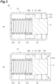
FIG.3(a) is an enlarged cross-sectional view of a brush unit inFIG.1 .FIG.3(b) is an enlarged cross-sectional view illustrating a state before processing of a holder of the brush unit. -
FIG.4 is an enlarged cross-sectional view of a brush unit according to a first modification. -
FIG.5 is a cross-sectional view illustrating another form of a protrusion according to the first modification. -
FIG.6(a) is a cross-sectional view illustrating still another form of the protrusion according to the first modification.FIG.6(b) is a cross-sectional view taken along line VIb-VIb ofFIG.6(a) . -
FIG.7 is an enlarged cross-sectional view of a brush unit according to a second modification. -
FIG.8 is an exploded perspective view of a connection device including a shaft conductive part according to a modification. -
FIG.9 is an enlarged cross-sectional view of a connection device according to a second embodiment. -
FIG.10 is an enlarged cross-sectional view illustrating a connection device according to a modification of the second embodiment. - In the following, embodiments of the present disclosure will be described with reference to the drawings. Note that the same or corresponding elements in the drawings are denoted by the same reference signs to omit redundant description thereof.
- A first embodiment of a connection device will be described. As illustrated in
FIG.1 , aconnection device 1 according to the first embodiment electrically connects arotary shaft 2 rotatably supported by abearing 3 with a housing (conductor) 4. Therotary shaft 2 may be a shaft of an electric motor or a shaft coupled to the shaft of the electric motor via a gear. In the present embodiment, a part on anend portion 2a side of therotary shaft 2 is a hollow shaft (hollow structure). Note that the entirerotary shaft 2 may be a hollow shaft as well as theend portion 2a of therotary shaft 2. Thebearing 3 supports therotary shaft 2 so as to be rotatable about a rotation axis L. A type of thebearing 3 is not particularly limited as long as therotary shaft 2 can be rotatably supported. - The
housing 4 accommodates theconnection device 1, therotary shaft 2, thebearing 3, and the like. Thehousing 4 has conductivity. In the present embodiment, theconnection device 1 electrically connects therotary shaft 2 and thehousing 4 to form a conductive path having a lower resistance value than that of a conductive path from therotary shaft 2 to thehousing 4 via thebearing 3. - As illustrated in
FIGS. 1 and2 , theconnection device 1 includes a shaftconductive part 10 and abrush unit 20. The shaftconductive part 10 has conductivity. In addition, the shaftconductive part 10 has a shape having arecess 10a. The shaftconductive part 10 is attached to theend portion 2a of therotary shaft 2 such that anopening part 10b of therecess 10a faces outward. - In more detail, the shaft
conductive part 10 includes aball holder 11 and asteel ball 12. Theball holder 11 and thesteel ball 12 each have conductivity. Theball holder 11 has a shape having therecess 10a. As an example, theball holder 11 is formed by pressing a steel plate. - The
steel ball 12 may be, for example, a ball for use for a bearing. Thesteel ball 12 is attached to a bottom 10c of therecess 10a of theball holder 11. Here, as an example, thesteel ball 12 is fitted into a hole provided in the bottom 10c of therecess 10a of theball holder 11 and is fixed by caulking. Thus, thesteel ball 12 is provided at the bottom 10c of therecess 10a in the shaftconductive part 10, and configures an abutting part that has a protrusion shape and abuts on the brush unit 20 (an end surface S of a brush 22). Thesteel ball 12 is attached to theball holder 11 such that a center of thesteel ball 12 is located on the rotation axis L, which is a rotation center of therotary shaft 2. - An outer peripheral surface of the
ball holder 11 is provided with afitting part 11a fitted in and fixed to an innerperipheral surface 2b of theend portion 2a of therotary shaft 2. Theball holder 11 is fitted in and fixed to the innerperipheral surface 2b of theend portion 2a of therotary shaft 2 such that theopening part 10b of therecess 10a faces outward. Thefitting part 11a of theball holder 11 and the innerperipheral surface 2b of therotary shaft 2 are engaged with each other. Therefore, theball holder 11 rotates integrally with therotary shaft 2. Thesteel ball 12 abuts on one end portion (the end surface S of the brush 22) of thebrush unit 20 in therecess 10a of theball holder 11. - The one end portion of the
brush unit 20 is inserted into therecess 10a of the shaftconductive part 10 to abut on thesteel ball 12 provided at the bottom 10c of therecess 10a. The other end portion of thebrush unit 20 is attached to thehousing 4. Thebrush unit 20 electrically connects the shaftconductive part 10 attached to therotary shaft 2 and thehousing 4. In more detail, thebrush unit 20 includes aholder 21, thebrush 22, and a spring (biasing part) 23. - The
holder 21 has a concave shape provided with anopening part 21a. Theholder 21 has conductivity. As a material of theholder 21, for example, metal (steel) having conductivity can be used. An end portion of theholder 21 on the side where theopening part 21a is provided is inserted into therecess 10a of the shaftconductive part 10. The other end portion of theholder 21 is attached to thehousing 4. In the present embodiment, thehousing 4 has arecess 4a on the rotation axis L serving as the rotation center of therotary shaft 2. Theholder 21 is attached to thehousing 4 with the other end portion being inserted into therecess 4a. As a result, thehousing 4 and theholder 21 are electrically connected to each other. - The
brush 22 is arranged in theholder 21. Thebrush 22 has conductivity. Thebrush 22 is slidable along the rotation axis L in theholder 21. As thebrush 22, for example, a carbon brush can be used. In thebrush 22, the end surface S on the bottom 10c side (thesteel ball 12 side) of therecess 10a of the shaftconductive part 10 abuts on thesteel ball 12. In other words, the end surface S is an abutting surface that abuts on thesteel ball 12. A shape of the end surface S may be flat, a concave shape (as an example, a shape recessed in an arc shape), or a protrusion shape (as an example, a shape protruding in an arc shape). In the present embodiment, the end surface S need only be in point contact with thesteel ball 12. - Note that the
steel ball 12 is provided such that the center of thesteel ball 12 is located on the rotation axis L as described above. Therefore, the end surface S of thebrush 22 and thesteel ball 12 are in point contact with each other on the rotation axis L. As a result, even when the shaftconductive part 10 rotates together with therotary shaft 2, a position of a contact point between the end surface S of thebrush 22 and thesteel ball 12 is not deviated. In other words, a difference in peripheral speed between the end surface S and thesteel ball 12 is zero at a connection part between them. - The
spring 23 is arranged between a bottom 21b of theholder 21 and thebrush 22. Thespring 23 has conductivity. Thespring 23 is a coil-shaped compression spring. Thespring 23 urges thebrush 22 toward theopening part 21a of theholder 21. In other words, thespring 23 biases thebrush 22 in a direction in which thebrush 22 approaches thesteel ball 12. As a result, thebrush 22 is brought into point contact with thesteel ball 12 in a state where theconnection device 1 is attached. In other words, thebrush 22 and thesteel ball 12 are electrically connected. - Here, as illustrated in
FIG.3(a) , thebrush 22 has afirst brush part 22a and asecond brush part 22b. Thefirst brush part 22a has the end surface S abutting on thesteel ball 12 at an end portion on a side where thebrush unit 20 is inserted into therecess 10a of the shaftconductive part 10. In the present embodiment, thefirst brush part 22a has a columnar shape with the rotation axis L as an axis. - The
second brush part 22b is connected to thefirst brush part 22a. Thesecond brush part 22b is located closer to the bottom 21b of theholder 21 than thefirst brush part 22a. Thespring 23 is arranged between thesecond brush part 22b and the bottom 21b of theholder 21. In other words, thesecond brush part 22b has one end connected to thefirst brush part 22a and the other end portion biased by thespring 23. Thesecond brush part 22b has a recess h on a surface opposed to the bottom 21b of theholder 21. An end portion of thespring 23 is fitted into the recess h. As a result, deviation of the position of thespring 23 with respect to thebrush 22 is suppressed. - The
second brush part 22b has a larger outer shape than thefirst brush part 22a in a direction (direction orthogonal to the rotation axis L) orthogonal to a biasing direction (direction along the rotation axis L) of thespring 23. Note that, for example, the fact that the outer shape of thesecond brush part 22b is larger than the outer shape of thefirst brush part 22a means that thefirst brush part 22a is located inside an outer edge of thesecond brush part 22b when viewed along an alignment direction of thesecond brush part 22b and thefirst brush part 22a. In the present embodiment, thesecond brush part 22b has a columnar shape with the rotation axis L as an axis. Therefore, in the present embodiment, thesecond brush part 22b has an outer diameter larger than an outer diameter of thefirst brush part 22a. - The
holder 21 has acylindrical part 21c extending along the rotation axis L. Thebrush 22 is held by theholder 21 while having a moving direction restricted by abutting of an outer peripheral surface of thesecond brush part 22b on an inner peripheral surface of thecylindrical part 21c of theholder 21 so as to be slidable. - In addition, the
holder 21 has a projectingpart 21d that projects inward from theopening part 21a. In other words, the projectingpart 21d projects inward from an end portion of thecylindrical part 21c. A distal end portion of the projectingpart 21d is opposed to an outer peripheral surface of thefirst brush part 22a. Here, in thesecond brush part 22b, a surface to which thefirst brush part 22a is connected is referred to as a connection surface (surface) S1. In other words, the connection surface S1 is a surface of thesecond brush part 22b facing theopening part 21a side. The projectingpart 21d is opposed to the connection surface S1 in the biasing direction (direction along the rotation axis L) of thespring 23. In this state, the connection surface S1 of thesecond brush part 22b is caught by the projectingpart 21d, thereby preventing thebrush 22 from falling off from theholder 21. - As illustrated in
FIG. 3(b) , the projectingpart 21d may be formed by bending (e.g., hot curling) the end portion of thecylindrical part 21c of theholder 21. In other words, theholder 21, thebrush 22, and thespring 23 are integrated with each other by forming the projectingpart 21d by bending in a state where thespring 23 and thebrush 22 are accommodated in theholder 21. This prevents thebrush 22 from falling off from theholder 21 in a state where thesteel ball 12 is not abutting on the brush 22 (e.g., a state at the time of assembling thebrush unit 20 to thehousing 4, a state before assembling thebrush unit 20, and the like). - In the present embodiment, the projecting
part 21d extends over an entire circumferential area of the end portion of thecylindrical part 21c. In other words, the projectingpart 21d has an annular shape. Not limited thereto, one or a plurality of the projectingparts 21d may be provided intermittently along the circumferential direction of the end portion (openingpart 21a) of thecylindrical part 21c. - Next, a conductive path between the
rotary shaft 2 and thehousing 4 in a case where theconnection device 1 is used will be described. In the present embodiment, theball holder 11, thesteel ball 12, theholder 21, thebrush 22, and thespring 23 have conductivity. Therefore, therotary shaft 2 is electrically connected to thehousing 4 via theball holder 11, thesteel ball 12, thebrush 22, thespring 23, and theholder 21. In other words, theball holder 11, thesteel ball 12, thebrush 22, thespring 23, and theholder 21 form a conductive path electrically connecting therotary shaft 2 and thehousing 4. Furthermore, therotary shaft 2 is electrically connected to thehousing 4 also via theball holder 11, thesteel ball 12, thebrush 22, and theholder 21. In other words, thebrush 22 and theholder 21 are electrically directly connected to each other without via thespring 23. Thus, theball holder 11, thesteel ball 12, thebrush 22, and theholder 21 form a conductive path electrically connecting therotary shaft 2 and thehousing 4. As a result, therotary shaft 2 and thehousing 4 are electrically connected to each other even when therotary shaft 2 is in a rotating state. - As described in the foregoing, in this
brush unit 20, theholder 21 attached to thehousing 4 and thebrush 22 abutting on the shaftconductive part 10 attached to therotary shaft 2 are electrically connected to each other directly and/or via thespring 23. Since theholder 21 is attached to therecess 4a of thehousing 4, thebrush unit 20 can electrically connect the shaftconductive part 10 attached to therotary shaft 2 and thehousing 4 to each other with a simple configuration. In addition, theholder 21 is provided with the projectingpart 21d. As a result, thebrush unit 20 can prevent thebrush 22 from jumping out (coming off) from theopening part 21a of theholder 21, and can be easily assembled to thehousing 4. Thus, thebrush unit 20 and theconnection device 1 including thebrush unit 20 enable improvement of assemblability to thehousing 4 while ensuring conductivity with a simple configuration. - Next, a first modification of the brush unit will be described. As illustrated in
FIG.4 , abrush unit 20A according to the first modification includes aholder 21A having a different shape instead of theholder 21 according to the first embodiment. Aprotrusion 21e protruding toward anopening part 21a is provided at a bottom 21b in theholder 21A. An end portion of aspring 23 is fitted to the outside of theprotrusion 21e. In the present modification, theprotrusion 21e has a cylindrical shape. Here, theprotrusion 21e abuts on an inner peripheral surface circumference of the coil-shapedspring 23 and holds thespring 23. - In this case, the
brush unit 20A can hold the coil-shapedspring 23 from the inside by theprotrusion 21e provided at the bottom 21b of theholder 21A. This enables thebrush unit 20A and a connection device including thebrush unit 20A to have improved assemblability of thebrush unit 20A. - Note that the
protrusion 21e is not limited to have a cylindrical shape. For example, as illustrated inFIG.5 , theprotrusion 21e may have a projectingpart 21f that projects outward at a distal end portion of theprotrusion 21e. Thespring 23 may be hooked on the projectingpart 21f. In this case, theholder 21A of thebrush unit 20A can more firmly hold thespring 23 by theprotrusion 21e and the projectingpart 21f. - Furthermore, as illustrated in
FIGS. 6(a) and 6(b) , theprotrusion 21e may be provided with a plurality of projectingparts 21g protruding outward at the distal end portion of theprotrusion 21e. In the example shown inFIGS. 6(a) and 6(b) , as an example, three projectingparts 21g are provided at equal intervals along a circumferential direction of theprotrusion 21e. Note that inFIG.6(b) , thespring 23 is indicated by an imaginary line to indicate the projectingpart 21g. The projectingpart 21g may be formed, for example, by pushing out the end portion of theprotrusion 21e toward the outside. The projectingpart 21g may be a staking tab. Thespring 23 is hooked on the plurality of projectingparts 21g. In other words, the projectingpart 21g holds thespring 23. In this case, theholder 21A of thebrush unit 20A can more firmly hold thespring 23 by theprotrusion 21e and the projectingpart 21g. - Next, a second modification of the brush unit will be described. As illustrated in
FIG.7 , abrush unit 20B according to the second modification includes aholder 21B having a different shape instead of theholder 21 according to the first embodiment. In a direction orthogonal to a biasing direction of aspring 23, an outer diameter of the coil-shapedspring 23 is smaller than an outer shape (outer diameter) of asecond brush part 22b of thebrush 22. Theholder 21B has aspring surrounding part 21h that surrounds an outer peripheral part of thespring 23, and a secondbrush surrounding part 21j that surrounds thesecond brush part 22b. In the present modification, each of thespring surrounding part 21h and the secondbrush surrounding part 21j has a cylindrical shape. - In the direction orthogonal to the biasing direction of the
spring 23, an inner dimension (inner diameter) of thespring surrounding part 21h is smaller than an inner dimension (inner diameter) of the secondbrush surrounding part 21j. The inner diameter of thespring surrounding part 21h is preferably large enough to surround (hold) thespring 23 accommodated inside while suppressing rattling. - As described above, the
spring surrounding part 21h and the secondbrush surrounding part 21j are different in size (diameter). Therefore, thespring surrounding part 21h and the secondbrush surrounding part 21j are coupled to each other by anannular coupling part 21k. Thecoupling part 21k extends outward from an outer peripheral surface of thespring surrounding part 21h along the direction orthogonal to the biasing direction of thespring 23. In other words, a connection part between thespring surrounding part 21h and the secondbrush surrounding part 21j is a stepped part. - The
brush unit 20B is attached to ahousing 4 by fitting thespring surrounding part 21h of theholder 21B into arecess 4a provided in thehousing 4. Here, therecess 4a is provided on aninner surface 4b of thehousing 4. When thespring surrounding part 21h of theholder 21B is fitted into therecess 4a, thecoupling part 21k of theholder 21B is brought to abut on theinner surface 4b of thehousing 4. In other words, in a state where thebrush unit 20B is attached to thehousing 4, thespring surrounding part 21h and thecoupling part 21k of theholder 21 are electrically connected to thehousing 4. - As described above, in the
holder 21B, the inner dimension of thespring surrounding part 21h that surrounds thespring 23 is smaller than the inner dimension of the secondbrush surrounding part 21j. Therefore, theholder 21B can hold the coil-shapedspring 23 from the outside by thespring surrounding part 21h while suppressing rattling. This enables thebrush unit 20B and a connection device including thebrush unit 20B to have improved assemblability of thebrush unit 20B. - When the
brush unit 20B is attached to thehousing 4, thespring surrounding part 21h and thecoupling part 21k abut on thehousing 4. In other words, in thebrush unit 20B, in addition to thespring surrounding part 21h fitted into therecess 4a, thecoupling part 21k also serves as a conductive path between theholder 21B and thehousing 4. Therefore, when thebrush unit 20B is attached to thehousing 4, the conductive performance between theholder 21B and thehousing 4 can be improved. - Although the first embodiment of the connection device and the various modifications of the brush unit have been described above, the connection device and the brush unit are not limited to the above embodiment and various modifications. For example, as in a shaft
conductive part 10A illustrated inFIG.8 , one or a plurality ofholes 11b may be provided around asteel ball 12 in aball holder 11. For example, there is a case where therotary shaft 2 is a hollow shaft, and a lubricating oil is caused to flow in therotary shaft 2. Even in such a case, by using the shaftconductive part 10A provided with thehole 11b in theball holder 11, it is possible to prevent a flow of the lubricating oil in therotary shaft 2 from being hindered. Note that the shaftconductive part 10A having thehole 11b is not limited to being attached to therotary shaft 2 through which the lubricating oil is caused to flow, and may be attached to therotary shaft 2 through which the lubricating oil is not caused to flow. - A second embodiment of the connection device will be described. As illustrated in
FIG.9 , a connection device 1C according to the second embodiment electrically connects arotary shaft 2 and ahousing 4, similarly to theconnection device 1 according to the first embodiment. The connection device 1C is configured to further improve conductivity between therotary shaft 2 and thehousing 4. Specifically, the connection device 1C includes a shaftconductive part 10C and a brush unit 20C. - The shaft
conductive part 10C includes a ball holder 11C and asteel ball 12. The ball holder 11C has a shape having arecess 10a. Anaccommodation part 10d is formed at a bottom 10c of therecess 10a of the ball holder 11C. Thesteel ball 12 is accommodated in theaccommodation part 10d. Thesteel ball 12 may be fixed to theaccommodation part 10d by caulking in theaccommodation part 10d, or may be accommodated in theaccommodation part 10d so as to be movable in and out. Similarly to the shaftconductive part 10A described with reference toFIG.8 , one or a plurality ofholes 11b are provided in the bottom 10c of therecess 10a of theball holder 11. - The brush unit 20C includes a
holder 21, abrush 22, a spring (biasing part) 23, anelectrode 24, and awiring 25. Theelectrode 24 has conductivity. Theelectrode 24 is arranged at a bottom 21b of theholder 21. Theelectrode 24 has aprotrusion 24a that protrudes toward thebrush 22 side. Thespring 23 is arranged between theelectrode 24 and thebrush 22. An end portion of thespring 23 is fitted into the outside of theprotrusion 24a. Theprotrusion 24a can position thespring 23. Note that theelectrode 24 is pressed against the bottom 21b of theholder 21 by being biased by thespring 23. - One end portion of the
wiring 25 is connected to thewiring 25. The other end portion of thewiring 25 is connected to thebrush 22. Thewiring 25 electrically connects theelectrode 24 and thebrush 22. Thewiring 25 has flexibility, for example. Even when an interval between theelectrode 24 and thebrush 22 changes, thewiring 25 maintains a state in which thewiring 25 and thebrush 22 are electrically connected. - The
wiring 25 passes through the inside of the coil-shapedspring 23. In the state where the opposite end portions of thewiring 25 are connected to theelectrode 24 and thebrush 22, respectively, thebrush 22, thespring 23, theelectrode 24, and thewiring 25 are integrated with each other. This enables the connection device 1C to have improved assemblability when thebrush 22, thespring 23, theelectrode 24, and thewiring 25 are assembled to theholder 21. - A projecting
part 21d of theholder 21 may be formed by bending similarly to thebrush unit 20 described with reference toFIG.3(b) . - Next, a conductive path between the
rotary shaft 2 and thehousing 4 in a case where the connection device 1C is used will be described. In the present embodiment, as in the first embodiment, therotary shaft 2 is electrically connected to thehousing 4 via theball holder 11, thesteel ball 12, thebrush 22, and theholder 21. - In addition, the connection device 1C according to the present embodiment includes the
electrode 24 and thewiring 25. Therefore, in the present embodiment, therotary shaft 2 is electrically connected to thehousing 4 also via theball holder 11, thesteel ball 12, thebrush 22, thewiring 25, theelectrode 24, and theholder 21. Thus, in the connection device 1C, thebrush 22 and theelectrode 24 are connected by thewiring 25. In addition, in the connection device 1C, theelectrode 24 is pressed against the bottom 21b of theholder 21 by thespring 23. This enables the connection device 1C to have improved conductivity between thebrush 22 and theholder 21. - As described above, the brush unit 20C and the connection device 1C including the brush unit 20C enable improvement of assemblability to the
housing 4 while ensuring high conductivity with a simple configuration. - In the connection device 1C according to the second embodiment, the
electrode 24 abuts on the bottom 21b of the concave-shapedholder 21. The bottom 21b may be formed by a projecting part that projects from acylindrical part 21c of theholder 21. Specifically, abrush unit 20D of aconnection device 1D illustrated inFIG.10 includes aholder 21D instead of theholder 21 of thebrush unit 20 according to the second embodiment. - The
holder 21D includes a projectingpart 21m that forms a bottom 21b of the concave-shapedholder 21D. The projectingpart 21m is provided at an end portion of acylindrical part 21c on a side opposite to anopening part 21a side. The projectingpart 21m projects inward from the end portion of thecylindrical part 21c. The projectingpart 21m abuts on anelectrode 24. In other words, theelectrode 24 is arranged at the bottom 21b of the concave-shapedholder 21D formed by the projectingpart 21m. - The projecting
part 21m may be formed by bending the end portion of thecylindrical part 21c similarly to thebrush unit 20 described with reference toFIG.3(b) . In this case, the projectingpart 21m is formed by bending in a state where abrush 22, aspring 23, theelectrode 24, and awiring 25 are accommodated in theholder 21D. This enables theconnection device 1D to have improved assemblability of thebrush unit 20D. - Although the embodiments of the present disclosure have been described in the foregoing, the present disclosure is not limited to the above-described embodiments. For example, the
first brush part 22a is not limited to a columnar shape, and may have a quadrangular prism shape. Although the coil-shapedspring 23 is used as the biasing part that biases thebrush 22 and the like, a biasing part having another configuration may be used as long as thebrush 22 and the like can be biased. The shaftconductive parts steel ball 12. The shaftconductive part 10 and the like may be configured to be able to abut on the end surface S of the brush 22 (e.g., configured to have a protrusion). In addition, the present disclosure is not limited to the configuration in which thesteel ball 12 is provided in the shaftconductive part 10 or the like. A steel ball may be attached to a distal end portion of thebrush 22, and the steel ball may abut on a bottom surface of therecess 10a such as the shaftconductive part 10. - Although the
connection device rotary shaft 2 and thehousing 4, a conductor other than thehousing 4 may be electrically connected to therotary shaft 2. Theelectrode 24 and thewiring 25 described in the second embodiment may be applied to theconnection device 1 according to the first embodiment and to the various modifications. In addition, at least a part of the various embodiments and various modifications described above may be freely and selectively combined with each other. -
- 1, 1C, 1D connection device
- 2 rotary shaft
- 4 housing (conductor)
- 10, 10A, 10C shaft conductive part
- 20, 20A, 20B, 20C, 20D brush unit
- 21, 21A, 21B, 21D holder
- 21a opening part
- 21d projecting part
- 21e protrusion
- 21h spring surrounding part
- 21j second brush surrounding part (part surrounding second brush part)
- 22 brush
- 22a first brush part
- 22b second brush part
- 23 spring (biasing part)
- 24 electrode
- 25 wiring
- S end surface (abutting surface)
- S1 connection surface (surface of second brush part to which first brush part is connected)
Claims (5)
- A brush unit attached to a conductor and abutting on a shaft conductive part provided on a rotary shaft to electrically connect the conductor and the shaft conductive part,
the brush unit comprising:a holder of a concave shape attached to the conductor, having conductivity, and having an opening part provided on a side of the shaft conductive part;a brush accommodated in the holder, abutting on the shaft conductive part via the opening part, and having conductivity; anda biasing part having conductivity, arranged between a bottom in the holder and the brush, and biasing the brush toward a side of the opening part, whereinthe brush includesa first brush part having an abutting surface abutting on the shaft conductive part, anda second brush part having one end portion connected to the first brush part and the other end portion biased by the biasing part,the second brush part having an outer shape larger than an outer shape of the first brush part in a direction orthogonal to a biasing direction of the biasing part,the holder includes a projecting part projecting inward from the opening part, andthe projecting part being opposed to a surface of the second brush part to which the first brush part is connected in the biasing direction of the biasing part. - The brush unit according to claim 1, whereinthe biasing part is a spring of a coil shape, andat the bottom of the holder, a protrusion to which an end portion of the spring is fitted on an outer side is provided.
- The brush unit according to claim 1, whereinthe biasing part is a spring of a coil shape,an outer diameter of the spring, in the direction orthogonal to the biasing direction of the biasing part, is smaller than an outer shape of the second brush part,the holder has a spring surrounding part surrounding an outer peripheral part of the spring, andan inner dimension of the spring surrounding part, in the direction orthogonal to the biasing direction of the biasing part, is smaller than an inner dimension of a part surrounding the second brush part in the holder.
- The brush unit according to claim 1, further comprising:an electrode arranged at a bottom of the holder of a concave shape; anda wiring electrically connecting the electrode and the brush, whereinthe biasing part is arranged between the electrode and the brush.
- A connection device electrically connecting a rotary shaft and a conductor, the connection device comprising:a shaft conductive part having a recess, attached to an end portion of the rotary shaft such that an opening part of the recess faces outward, and having conductivity; andthe brush unit according to any one of claims 1 to 4, the brush unit having one end portion inserted into the recess of the shaft conductive part to abut on a bottom of the recess, and the other end portion attached to the conductor to electrically connect the shaft conductive part and the conductor.
Applications Claiming Priority (2)
| Application Number | Priority Date | Filing Date | Title |
|---|---|---|---|
| JP2022151603 | 2022-09-22 | ||
| PCT/JP2023/033600 WO2024063013A1 (en) | 2022-09-22 | 2023-09-14 | Brush unit and connection device |
Publications (1)
| Publication Number | Publication Date |
|---|---|
| EP4568028A1 true EP4568028A1 (en) | 2025-06-11 |
Family
ID=90454395
Family Applications (1)
| Application Number | Title | Priority Date | Filing Date |
|---|---|---|---|
| EP23868134.0A Pending EP4568028A1 (en) | 2022-09-22 | 2023-09-14 | Brush unit and connection device |
Country Status (4)
| Country | Link |
|---|---|
| US (1) | US20260081394A1 (en) |
| EP (1) | EP4568028A1 (en) |
| JP (1) | JPWO2024063013A1 (en) |
| WO (1) | WO2024063013A1 (en) |
Families Citing this family (1)
| Publication number | Priority date | Publication date | Assignee | Title |
|---|---|---|---|---|
| JP2025103526A (en) * | 2023-12-27 | 2025-07-09 | 日本精工株式会社 | Brush unit and connecting device |
Family Cites Families (5)
| Publication number | Priority date | Publication date | Assignee | Title |
|---|---|---|---|---|
| JPS4831505U (en) * | 1971-08-20 | 1973-04-17 | ||
| JPH0718024U (en) * | 1993-08-31 | 1995-03-31 | エヌティエヌ株式会社 | Grounding device for bearings of railroad vehicle axles |
| JPH09149583A (en) * | 1995-11-24 | 1997-06-06 | Hitachi Koki Co Ltd | Brush equipment |
| JP6242566B2 (en) | 2012-02-27 | 2017-12-06 | 三菱重工業株式会社 | Electric corrosion prevention device |
| JP7347229B2 (en) * | 2020-01-22 | 2023-09-20 | 株式会社デンソー | dc motor |
-
2023
- 2023-09-14 US US19/106,637 patent/US20260081394A1/en active Pending
- 2023-09-14 EP EP23868134.0A patent/EP4568028A1/en active Pending
- 2023-09-14 WO PCT/JP2023/033600 patent/WO2024063013A1/en not_active Ceased
- 2023-09-14 JP JP2024548234A patent/JPWO2024063013A1/ja active Pending
Also Published As
| Publication number | Publication date |
|---|---|
| JPWO2024063013A1 (en) | 2024-03-28 |
| US20260081394A1 (en) | 2026-03-19 |
| WO2024063013A1 (en) | 2024-03-28 |
Similar Documents
| Publication | Publication Date | Title |
|---|---|---|
| EP2554437B1 (en) | Rotary connector device | |
| US8758024B2 (en) | Rotary connector device | |
| US4209213A (en) | Brush holder and slip ring assembly | |
| US7855479B2 (en) | Noise suppression structure of blower motor | |
| US9583995B2 (en) | Motor | |
| EP3429067B1 (en) | Motor, end cap and manufacturing method thereof | |
| CN111937253B (en) | Connector | |
| US6603235B1 (en) | Small-sized motor having a brush unit with an improved brush arm and terminal connections | |
| US20260081394A1 (en) | Brush unit and connection device | |
| US20250219339A1 (en) | Connection device | |
| CN102072266B (en) | Driving device | |
| US11228221B2 (en) | Motor | |
| JP5222199B2 (en) | Rotary sensor | |
| US6495939B1 (en) | Coreless motor having tubular housing with end mounting portions | |
| JP7081160B2 (en) | motor | |
| WO2019244872A1 (en) | Motor | |
| CN111668974A (en) | Brush holding structure and motor | |
| CN112805904A (en) | Motor | |
| US11942740B2 (en) | Motor having columnar brush | |
| JP4430592B2 (en) | motor | |
| JP2024139176A (en) | Connecting Devices | |
| JP6969393B2 (en) | motor | |
| JP5066135B2 (en) | Vibration motor | |
| KR102759872B1 (en) | Rotating connector device | |
| CN219554768U (en) | Electric pump |
Legal Events
| Date | Code | Title | Description |
|---|---|---|---|
| STAA | Information on the status of an ep patent application or granted ep patent |
Free format text: STATUS: THE INTERNATIONAL PUBLICATION HAS BEEN MADE |
|
| PUAI | Public reference made under article 153(3) epc to a published international application that has entered the european phase |
Free format text: ORIGINAL CODE: 0009012 |
|
| STAA | Information on the status of an ep patent application or granted ep patent |
Free format text: STATUS: REQUEST FOR EXAMINATION WAS MADE |
|
| 17P | Request for examination filed |
Effective date: 20250305 |
|
| AK | Designated contracting states |
Kind code of ref document: A1 Designated state(s): AL AT BE BG CH CY CZ DE DK EE ES FI FR GB GR HR HU IE IS IT LI LT LU LV MC ME MK MT NL NO PL PT RO RS SE SI SK SM TR |
|
| DAV | Request for validation of the european patent (deleted) | ||
| DAX | Request for extension of the european patent (deleted) |