EP4567982A1 - Battery pack - Google Patents
Battery pack Download PDFInfo
- Publication number
- EP4567982A1 EP4567982A1 EP24211222.5A EP24211222A EP4567982A1 EP 4567982 A1 EP4567982 A1 EP 4567982A1 EP 24211222 A EP24211222 A EP 24211222A EP 4567982 A1 EP4567982 A1 EP 4567982A1
- Authority
- EP
- European Patent Office
- Prior art keywords
- bent
- battery cells
- battery
- plates
- plate
- Prior art date
- Legal status (The legal status is an assumption and is not a legal conclusion. Google has not performed a legal analysis and makes no representation as to the accuracy of the status listed.)
- Pending
Links
Images









Classifications
-
- H—ELECTRICITY
- H01—ELECTRIC ELEMENTS
- H01M—PROCESSES OR MEANS, e.g. BATTERIES, FOR THE DIRECT CONVERSION OF CHEMICAL ENERGY INTO ELECTRICAL ENERGY
- H01M50/00—Constructional details or processes of manufacture of the non-active parts of electrochemical cells other than fuel cells, e.g. hybrid cells
- H01M50/20—Mountings; Secondary casings or frames; Racks, modules or packs; Suspension devices; Shock absorbers; Transport or carrying devices; Holders
- H01M50/218—Mountings; Secondary casings or frames; Racks, modules or packs; Suspension devices; Shock absorbers; Transport or carrying devices; Holders characterised by the material
- H01M50/22—Mountings; Secondary casings or frames; Racks, modules or packs; Suspension devices; Shock absorbers; Transport or carrying devices; Holders characterised by the material of the casings or racks
- H01M50/222—Inorganic material
- H01M50/224—Metals
-
- H—ELECTRICITY
- H01—ELECTRIC ELEMENTS
- H01M—PROCESSES OR MEANS, e.g. BATTERIES, FOR THE DIRECT CONVERSION OF CHEMICAL ENERGY INTO ELECTRICAL ENERGY
- H01M50/00—Constructional details or processes of manufacture of the non-active parts of electrochemical cells other than fuel cells, e.g. hybrid cells
- H01M50/20—Mountings; Secondary casings or frames; Racks, modules or packs; Suspension devices; Shock absorbers; Transport or carrying devices; Holders
- H01M50/262—Mountings; Secondary casings or frames; Racks, modules or packs; Suspension devices; Shock absorbers; Transport or carrying devices; Holders with fastening means, e.g. locks
- H01M50/264—Mountings; Secondary casings or frames; Racks, modules or packs; Suspension devices; Shock absorbers; Transport or carrying devices; Holders with fastening means, e.g. locks for cells or batteries, e.g. straps, tie rods or peripheral frames
-
- H—ELECTRICITY
- H01—ELECTRIC ELEMENTS
- H01M—PROCESSES OR MEANS, e.g. BATTERIES, FOR THE DIRECT CONVERSION OF CHEMICAL ENERGY INTO ELECTRICAL ENERGY
- H01M50/00—Constructional details or processes of manufacture of the non-active parts of electrochemical cells other than fuel cells, e.g. hybrid cells
- H01M50/20—Mountings; Secondary casings or frames; Racks, modules or packs; Suspension devices; Shock absorbers; Transport or carrying devices; Holders
- H01M50/244—Secondary casings; Racks; Suspension devices; Carrying devices; Holders characterised by their mounting method
-
- H—ELECTRICITY
- H01—ELECTRIC ELEMENTS
- H01M—PROCESSES OR MEANS, e.g. BATTERIES, FOR THE DIRECT CONVERSION OF CHEMICAL ENERGY INTO ELECTRICAL ENERGY
- H01M50/00—Constructional details or processes of manufacture of the non-active parts of electrochemical cells other than fuel cells, e.g. hybrid cells
- H01M50/20—Mountings; Secondary casings or frames; Racks, modules or packs; Suspension devices; Shock absorbers; Transport or carrying devices; Holders
- H01M50/204—Racks, modules or packs for multiple batteries or multiple cells
-
- H—ELECTRICITY
- H01—ELECTRIC ELEMENTS
- H01M—PROCESSES OR MEANS, e.g. BATTERIES, FOR THE DIRECT CONVERSION OF CHEMICAL ENERGY INTO ELECTRICAL ENERGY
- H01M50/00—Constructional details or processes of manufacture of the non-active parts of electrochemical cells other than fuel cells, e.g. hybrid cells
- H01M50/20—Mountings; Secondary casings or frames; Racks, modules or packs; Suspension devices; Shock absorbers; Transport or carrying devices; Holders
- H01M50/204—Racks, modules or packs for multiple batteries or multiple cells
- H01M50/207—Racks, modules or packs for multiple batteries or multiple cells characterised by their shape
- H01M50/209—Racks, modules or packs for multiple batteries or multiple cells characterised by their shape adapted for prismatic or rectangular cells
-
- H—ELECTRICITY
- H01—ELECTRIC ELEMENTS
- H01M—PROCESSES OR MEANS, e.g. BATTERIES, FOR THE DIRECT CONVERSION OF CHEMICAL ENERGY INTO ELECTRICAL ENERGY
- H01M50/00—Constructional details or processes of manufacture of the non-active parts of electrochemical cells other than fuel cells, e.g. hybrid cells
- H01M50/20—Mountings; Secondary casings or frames; Racks, modules or packs; Suspension devices; Shock absorbers; Transport or carrying devices; Holders
- H01M50/218—Mountings; Secondary casings or frames; Racks, modules or packs; Suspension devices; Shock absorbers; Transport or carrying devices; Holders characterised by the material
- H01M50/22—Mountings; Secondary casings or frames; Racks, modules or packs; Suspension devices; Shock absorbers; Transport or carrying devices; Holders characterised by the material of the casings or racks
- H01M50/231—Mountings; Secondary casings or frames; Racks, modules or packs; Suspension devices; Shock absorbers; Transport or carrying devices; Holders characterised by the material of the casings or racks having a layered structure
-
- H—ELECTRICITY
- H01—ELECTRIC ELEMENTS
- H01M—PROCESSES OR MEANS, e.g. BATTERIES, FOR THE DIRECT CONVERSION OF CHEMICAL ENERGY INTO ELECTRICAL ENERGY
- H01M50/00—Constructional details or processes of manufacture of the non-active parts of electrochemical cells other than fuel cells, e.g. hybrid cells
- H01M50/20—Mountings; Secondary casings or frames; Racks, modules or packs; Suspension devices; Shock absorbers; Transport or carrying devices; Holders
- H01M50/249—Mountings; Secondary casings or frames; Racks, modules or packs; Suspension devices; Shock absorbers; Transport or carrying devices; Holders specially adapted for aircraft or vehicles, e.g. cars or trains
-
- H—ELECTRICITY
- H01—ELECTRIC ELEMENTS
- H01M—PROCESSES OR MEANS, e.g. BATTERIES, FOR THE DIRECT CONVERSION OF CHEMICAL ENERGY INTO ELECTRICAL ENERGY
- H01M50/00—Constructional details or processes of manufacture of the non-active parts of electrochemical cells other than fuel cells, e.g. hybrid cells
- H01M50/20—Mountings; Secondary casings or frames; Racks, modules or packs; Suspension devices; Shock absorbers; Transport or carrying devices; Holders
- H01M50/258—Modular batteries; Casings provided with means for assembling
-
- H—ELECTRICITY
- H01—ELECTRIC ELEMENTS
- H01M—PROCESSES OR MEANS, e.g. BATTERIES, FOR THE DIRECT CONVERSION OF CHEMICAL ENERGY INTO ELECTRICAL ENERGY
- H01M50/00—Constructional details or processes of manufacture of the non-active parts of electrochemical cells other than fuel cells, e.g. hybrid cells
- H01M50/20—Mountings; Secondary casings or frames; Racks, modules or packs; Suspension devices; Shock absorbers; Transport or carrying devices; Holders
- H01M50/262—Mountings; Secondary casings or frames; Racks, modules or packs; Suspension devices; Shock absorbers; Transport or carrying devices; Holders with fastening means, e.g. locks
-
- H—ELECTRICITY
- H01—ELECTRIC ELEMENTS
- H01M—PROCESSES OR MEANS, e.g. BATTERIES, FOR THE DIRECT CONVERSION OF CHEMICAL ENERGY INTO ELECTRICAL ENERGY
- H01M50/00—Constructional details or processes of manufacture of the non-active parts of electrochemical cells other than fuel cells, e.g. hybrid cells
- H01M50/20—Mountings; Secondary casings or frames; Racks, modules or packs; Suspension devices; Shock absorbers; Transport or carrying devices; Holders
- H01M50/271—Lids or covers for the racks or secondary casings
-
- H—ELECTRICITY
- H01—ELECTRIC ELEMENTS
- H01M—PROCESSES OR MEANS, e.g. BATTERIES, FOR THE DIRECT CONVERSION OF CHEMICAL ENERGY INTO ELECTRICAL ENERGY
- H01M50/00—Constructional details or processes of manufacture of the non-active parts of electrochemical cells other than fuel cells, e.g. hybrid cells
- H01M50/20—Mountings; Secondary casings or frames; Racks, modules or packs; Suspension devices; Shock absorbers; Transport or carrying devices; Holders
- H01M50/289—Mountings; Secondary casings or frames; Racks, modules or packs; Suspension devices; Shock absorbers; Transport or carrying devices; Holders characterised by spacing elements or positioning means within frames, racks or packs
-
- H—ELECTRICITY
- H01—ELECTRIC ELEMENTS
- H01M—PROCESSES OR MEANS, e.g. BATTERIES, FOR THE DIRECT CONVERSION OF CHEMICAL ENERGY INTO ELECTRICAL ENERGY
- H01M2220/00—Batteries for particular applications
- H01M2220/20—Batteries in motive systems, e.g. vehicle, ship, plane
-
- H—ELECTRICITY
- H01—ELECTRIC ELEMENTS
- H01M—PROCESSES OR MEANS, e.g. BATTERIES, FOR THE DIRECT CONVERSION OF CHEMICAL ENERGY INTO ELECTRICAL ENERGY
- H01M50/00—Constructional details or processes of manufacture of the non-active parts of electrochemical cells other than fuel cells, e.g. hybrid cells
- H01M50/20—Mountings; Secondary casings or frames; Racks, modules or packs; Suspension devices; Shock absorbers; Transport or carrying devices; Holders
- H01M50/204—Racks, modules or packs for multiple batteries or multiple cells
- H01M50/207—Racks, modules or packs for multiple batteries or multiple cells characterised by their shape
- H01M50/211—Racks, modules or packs for multiple batteries or multiple cells characterised by their shape adapted for pouch cells
-
- Y—GENERAL TAGGING OF NEW TECHNOLOGICAL DEVELOPMENTS; GENERAL TAGGING OF CROSS-SECTIONAL TECHNOLOGIES SPANNING OVER SEVERAL SECTIONS OF THE IPC; TECHNICAL SUBJECTS COVERED BY FORMER USPC CROSS-REFERENCE ART COLLECTIONS [XRACs] AND DIGESTS
- Y02—TECHNOLOGIES OR APPLICATIONS FOR MITIGATION OR ADAPTATION AGAINST CLIMATE CHANGE
- Y02E—REDUCTION OF GREENHOUSE GAS [GHG] EMISSIONS, RELATED TO ENERGY GENERATION, TRANSMISSION OR DISTRIBUTION
- Y02E60/00—Enabling technologies; Technologies with a potential or indirect contribution to GHG emissions mitigation
- Y02E60/10—Energy storage using batteries
Definitions
- the present disclosure relates to a battery pack with enhanced structural rigidity of a frame portion of a battery module.
- a secondary battery (or a rechargeable battery) is widely used in a mobile device, an auxiliary electric power device, or the like.
- secondary batteries are also attracting attention as a main power source for an electric vehicle, a hybrid electric vehicle, a plug-in hybrid electric vehicle, or the like, which are proposed as alternatives to conventional and diesel vehicles to solve various problems such as air pollution.
- a battery module in which a plurality of battery cells are stacked and then electrically connected in series and in parallel is used due to a need for a high-output and large-capacity battery.
- the battery cells are stacked in the battery module, and terminals exposed at both ends of each battery cell are electrically connected to provide a high voltage.
- a frame constituting an outer wall of the battery module uses aluminum and stainless steel (SUS) that can be welded and do not generate rust.
- a material of a side plate is determined according to a shape and a material of an end plate with a surface where a swelling force and a compression force required for assembly act in one direction according to a direction in which the battery cell is disposed. If the end plate and the side plate are made of different materials, a same material may be included inside the plate in a special case because welding does not reach a required strength.
- the battery module may have a flange shape protruding from a side surface thereof so as to be fixed to a frame portion of a battery pack at a plurality of positions.
- the flange requires sufficient thickness and rigidity to fix the module with a relatively heavy volume.
- Embodiments of the present disclosure provide a battery pack in which structural rigidity of a frame supporting battery cells of a battery module is strengthened and a space efficiency of a battery is improved by reducing a thickness when a battery module using roll forming is manufactured.
- a battery pack includes: a frame portion forming an accommodation space; a plurality of battery modules positioned in the accommodation space of the frame portion; a lower cover that covers a lower portion of the frame portion; and an upper cover that covers an upper portion of the frame portion.
- Each of the battery modules includes: a plurality of battery cells; a plurality of side plates including bent portions that are coupled to the frame portion and support side surfaces of the plurality of battery cells; and a plurality of end plates that connect ends of the side plates to each other.
- Each of the side plates may include an inner surface that supports the side surfaces of the battery cells, and each of the side plates may be bent along an upper edge to form a folded portion that is in contact with a surface of the side plate.
- the folded portion may be welded to the surface of the side plate.
- An end portion of the folded portion may include a bent portion protruding from the side plate.
- Each of the bent portions may include a plurality of screw holes and a plurality of cutout portions may be formed between the plurality of screw holes, and fastening members may be inserted into the screw holes to fix the bent portion to the frame portions.
- the cutout portions may be formed in trapezoidal shapes.
- Each of the side plates may include bending support portion formed at a lower portion of the side plate that supports a lower surface of the battery module.
- Each of the side plates may be roll formed.
- An insulating film may be attached to a surface of the side plate facing the battery cells.
- Each of the side plates may include a side surface that supports the side surfaces of the battery cells, and the side surface may include a bent connection portion that is bent and protrudes in a direction away from the side surfaces of the battery cells.
- An avoiding bent portion may be formed at an upper edge of each of the side plates, with the avoiding bent portion being bent in the direction away from the side surfaces of the battery cells.
- each of the side plates may be connected to the side surfaces of the battery cells using an adhesive, and each of the side plates may include an adhesive bent portion that is spaced apart from the side surfaces of the battery cells at a portion of the side plate where the adhesive is applied.
- Each of the side plates may include a first side surface that supports the side surfaces of the battery cells and a second side surface that is coupled to a connection flange coupled to the frame portion
- the connection flange may include a connection plate coupled to the second side surface of the side plate and a connection protruding portion protruding in a direction away from the side plate to be coupled to the frame portion.
- a portion of each of the side plates to which the connection plates may be coupled may be bent so that a bonding bent portion spaced apart from the side surfaces of the battery cells is formed.
- An adhesive may be applied between the bonding bent portion and the side surfaces of the battery cells.
- the side plates may include: a first side portion that includes a side surface supporting the side surfaces of the battery cells, wherein an upper end of the first side portion includes a first bent outward portion that is bent in a direction away from the battery cells; and a second side portion that is coupled to an upper end of the first side portion, wherein a lower end of the second side portion includes a second bent outward portion that is bent outward in the direction away from the battery cells and is coupled to the first bent outward portion.
- the first side portion and the second side portion may be roll formed.
- the battery pack may further include an insulating plate that includes a first end connected to a side surface of one of the end plates, a second end connected to a side surface of another one of the end plates, and side surfaces supporting the side surfaces of the battery cells.
- the insulating plate may include: a first insulating plate that includes ends connected to side surfaces of the end plates to support the side surfaces of the battery cells; and a second insulating plate that includes a portion welded to a side surface of the first insulating plate and ends connected to the side surfaces of the end plates to support the side surfaces of the battery cells.
- the first insulating plate may be bent along a lower edge thereof to form a first bending support portion supporting a lower surface of the battery module
- the second insulating plate may be bent along the lower edge thereof to form a second bending support portion supporting the lower surface of the battery module.
- a first upper bent portion may be formed at an upper portion of the first insulating plate and a first lower bent portion may be formed at a lower portion of the first insulating plate, a second upper bent portion may be formed at an upper portion of the second insulating plate and a second lower bent portion may be formed at a lower portion of the second insulating plate, and the first upper bent portion and the second upper bent portion may be welded to each other and the first lower bent portion and the second lower bent portion may be welded to each other.
- the first insulating plate and the second insulating plate may be roll formed.
- the side plates may be made of stainless steel.
- An insulating film may be attached to one or more inner surfaces of one or more of the side plates.
- a side plate supporting a battery cell may be formed of a SUS material or a steel material and rigidity of a plate portion where a battery module is connected to a frame portion may be improved such that durability thereof is improved.
- the side plate supporting the battery module may be manufactured using a roll forming method.
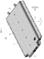
- FIG. 1 is a perspective view schematically showing a battery pack according to a first embodiment of the present disclosure
- FIG. 2 is an exploded perspective view schematically showing the battery pack of FIG. 1 .
- the battery pack 300 may include a frame portion 100 in which a plurality of frames are coupled to each other and an accommodation space is formed therein.
- a plurality of battery modules 200 are inserted into the accommodation space of the frame portion 100, a lower cover 50 covers a lower portion of the frame portion 100, and an upper cover 60 covers an upper portion of the frame portion 100.
- the frame portion 100 may include a first side frame 10 and a second side frame 20.
- a first end frame 30 and a second end frame 40 connect the first side frame 10 and the second side frame 20 to each other.
- the first side frame 10 may be coupled to one edge of the lower cover 50, and may be installed to support one side of the plurality of battery modules 200.
- the second side frame 20 may be coupled to the other edge of the lower cover 50 and may be installed to support the other side of the plurality of battery modules 200.
- the first end frame 30 may be installed to connect one end of the first side frame 10 and one end of the second side frame 20.
- one end of the first end frame 30 may be connected to the one end of the first side frame 10 by a fastening member 11
- the other end of the first end frame 30 may be connected to the one end of the second side frame 20 by the fastening member 11.
- the second end frame 40 may be installed to connect the other end of the first side frame 10 and the other end of the second side frame 20.
- one end of the second end frame 40 may be connected to the other end of the first side frame 10 by the fastening member 11
- the other end of the second end frame 40 may be connected to the other end of the second side frame 20 by the fastening member 11.
- the accommodation space may be formed inside the frame portion 100 such that the battery module 200 may be installed inside the accommodation space.
- the lower cover 50 may be coupled to the lower portion of the frame portion 100 and the upper cover 60 may be coupled to the upper portion of the frame portion 100, so that a battery cell 111 accommodated inside the frame portion 100 is supported.
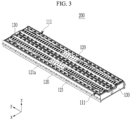
- FIG. 3 is a perspective view schematically showing the battery module according to the first embodiment of the present disclosure
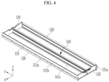
- FIG. 4 is a perspective view schematically showing a state in which a side plate and end plates of the battery module of FIG. 3 are coupled to each other.
- the battery module 200 may include a plurality of battery cells 111, a plurality of side plates 120 that support side surfaces of the plurality of battery cells 111 and are bent so that a portion of the side surface is coupled to the frame portion 100, and a plurality of end plates 130 connecting both ends of each of the plurality of side plates 120 to each other.
- the plurality of side plates 120 may be installed to support the side surfaces of the plurality of battery cells 111.
- the plurality of side plates 120 may include a first side plate and a second side plate that respectively support both opposing sides of the plurality of battery cells 111.
- the side plate, the first side plate, and the second side plate use the same reference numeral 120. That is, the first and second side plates 120 may be installed with the same size and shape, and hereinafter, the first and second side plates use the same reference numeral 120.
- the end plate 130 may be installed to connect both ends of each of the first and second side plates 120 to each other.
- the end plate may include first and second end plates 130.
- the first and second end plates may be installed with the same size and shape, and hereinafter, the first and second end plates use the same reference numeral 130.
- a portion of an edge of the side plate 120 along a length direction may be folded in a direction of one side surface.
- the side plate 120 may be installed to secure structural rigidity.
- a portion of the side plate 120 may be folded to enable an overlapping configuration of the plate so that the structural rigidity is secured.
- the side plate 120 may be formed of a SUS material or a steel material.
- an insulating plate 140 as shown in FIG. 4 may be installed at a position between rows of the plurality of battery modules 200 (further described below).
- FIG. 5 is a perspective view schematically showing the side plate according to the first embodiment of the present disclosure
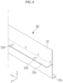
- FIG. 6 is a main portion perspective view schematically showing a portion of the side plate of FIG. 5
- FIG. 7 is a cross-sectional view schematically showing the side plate of FIG. 5 .
- the side plate 120 may have an inner surface that supports the side surfaces of the plurality of battery cells 111, and the side plate 120 may include a folding portion 121 that includes a portion folded along an upper edge to be in surface contact with an outer surface thereof. A portion of the side plate 120 may be bent so that the folding portion 121 is formed, and the folding portion 121 may be formed to increase a thickness of the side plate 120 along a width direction.
- the folding portion 121 may be formed to have a length corresponding to approximately half of a height direction (a z-axis direction) of the side plate 120.
- a bent portion 121a may protrude from an end portion of the folding portion 121 so as to protrude in a side surface direction of the side plate 120.
- a portion of the folding portion 121 formed outside the side plate 120 may be bent so that the bent portion 121a may protrude from the side plate.
- the side plate 120 at which the folding portion 121 and the bent portion 121a may be formed by roll forming.
- the side plate made of a SUS material or a steel material may be processed by the roll forming.
- bent portion 121a protrudes from a side surface of the side plate 120 is to allow the battery module 200 to be coupled to the frame portion 100 by a fastening member so that the battery module 200 is stably fixed to the frame portion 100.
- a plurality of bolt holes 121b may be formed in the bent portion 121a for coupling fastening members such as bolt members or the like.
- a bending support portion 121c may be formed at a lower portion of the side plate 120.
- the bending support portion 121c may be bent at a lower edge of the side plate 120, and may be formed at the lower portion of the side plate 120 to support a lower portion of the battery cell 111.
- the battery cell 111 may be stably fixed in a state in which the battery cell 111 is accommodated inside the frame portion 100.
- an insulating film 123 may be attached to a side surface of the side plate 120 contacting the battery cell 111. A portion of the insulating film 123 may protrude upward from the side plate 120 in a state in which it is attached to an entire surface where the battery cell 111 is in contact with the side plate 120.
- a pair of the side plates 120 may be connected to each other by a pair of the end plates 130.
- the plurality of battery modules 200 may be inserted into the frame portion 100, and the plurality of battery modules 200 may be disposed in two rows. While the present embodiment describes the plurality of battery modules 200 as being disposed in two rows inserted into the frame portion 100, the present disclosure is not necessarily limited thereto.
- the battery module 200 may be inserted as a single row in the frame portion 100 in a state in which the insulating plate 140 (described below) is removed.
- the insulating plate 140 may be installed at a position between rows of the plurality of battery modules 200. Both ends of the insulating plate 140 may be connected to the pair of end plates 130 at a position between the pair of side plates 120.
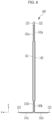
- FIG. 8 is a cross-sectional view schematically showing the insulating plate according to the first embodiment of the present disclosure.
- the insulating plate 140 may include first and second insulating plates 141 and 143. Both ends of the first and second insulating plates 141 and 143 may be connected to the pair of end plates 130. The first and second insulating plates 141 and 143 may be welded and coupled to each other in a state in which the first and second insulating plates 141 and 143 are connected to the pair of end plates 130.
- the insulating plate 140 may include the first insulating plate 141 that has both of its ends connected to side surfaces of the plurality of end plates 130 to support the side surfaces of the plurality of battery cells.
- the second insulating plate 143 that has a portion welded to a side surface of the first insulating plate 141 and has both ends connected to the side surfaces of the plurality of end plates 130 to support the side surfaces of the plurality of battery cells.
- the first insulating plate 141 may be installed to support side surfaces of the plurality of battery cells 111 disposed in a first row among the battery cells 111 that are disposed in two rows.
- a portion of the first insulating plate 141 along a length direction may be formed to be bent in a state in which both ends of the first insulating plate 141 are connected to the pair of end plates 130.
- One reason why the portion of the first insulating plate 141 along the length direction is bent is to couple the bent portion to the second insulating plate 143 by contacting the bent portion with the second insulating plate 143.
- Another reason why the portion of the first insulating plate 141 along the length direction is bent is to apply an adhesive to a space formed between the bent portion of the first insulating plate 141 and side surfaces of the battery cells 111.
- a side surface of the first insulating plate 141 may support the side surfaces of the battery cells 111, a first upper bent portion 141a may be formed at an upper portion of the first insulating plate 141, and a first lower bent portion 141b may be formed at a lower portion of the first insulating plate 141.
- the first upper bent portion 141a and the first lower bent portion 141b may be bent so that a space is formed between the first upper bent portion 141a and the first lower bent portion 141b and the side surface of the battery cell 111.
- the second insulating plate 143 may be installed to support side surfaces of the plurality of battery cells 111 disposed in a second row among the battery cells 111 that are disposed in two rows. A portion of the second insulating plate 143 along a length direction may be formed to be bent in a state in which both ends of the second insulating plate 143 are connected to the pair of end plates 130.
- a side surface of the second insulating plate 143 may support the side surfaces of the battery cells 111, a second upper bent portion 143a may be formed at an upper portion of the second insulating plate 143, and a second lower bent portion 143b may be formed at a lower portion of the second insulating plate 143.
- the first and second upper bent portions 141a and 143a may be in surface contact with each other, and the first and second lower bent portions 141b and 143b may be in surface contact with each other.
- Portions of the first and second upper bent portions 141a and 143a and portions of the first and second lower bent portions 141b and 143b that are in surface contact with each other may be welded and coupled to each other.
- Each of the first and second upper bent portions 141a and 143a and the first and second lower bent portions 141b and 143b may be formed so as to be retracted from positions of side surfaces of the first and second insulating plates 141 and 143 that are in contact with the battery cells 111.
- welding heat may not be transferred to the side surfaces of the first and second insulating plates 141 and 143 during a process in which the first and second upper bent portions 141a and 143a and the first and second lower bent portions 141b and 143b are welded to each other, and the durability of the first and second insulating plates 141 and 143 is thereby improved.
- a first bending support portion 141c that supports a lower surface of the battery module may be formed at a lower portion of the first insulating plate 141.
- a second bending support portion 143c that supports the lower surface of the battery module may be formed at a lower portion of the second insulating plate 143.
- the first bending support portion 141c and the second bending support portion 143c may protrude in opposite directions and be formed to support lower portions of the battery cells 111 in different rows.
- the insulating film 123 may be attached to the side surfaces of the first and second insulating plates 141 and 143.
- the side plate 120 supporting the battery cells 111 may be formed of a SUS material or a steel material and rigidity of a plate portion where the battery module 200 is connected to the frame portion 100 may be further improved, so that durability thereof is improved. Further, because the side plate 120 is manufactured using a roll forming method, a facility required for manufacturing the battery pack may be minimized so that a manufacturing cost is minimized.
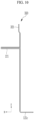
- FIG. 9 is a cross-sectional view schematically showing a side plate according to a second embodiment of the present disclosure.
- the same reference numerals as those in FIGS. 1 to 8 denote the same or similar member features having the same or similar function. Thus, detailed descriptions of the same reference numerals for each of other embodiments described below will be omitted.
- the side plate 220 may have one side surface supporting side surfaces of the plurality of battery cells 111, and the side plate 220 may include a bent connection portion 221 protruding in a direction of the other side surface by bending a portion of a side surface of the side plate 220.
- the bent connection portion 221 may have a portion between an upper edge and a lower edge of the side plate 220 and protrude outward.
- the bent connection portion 221 may protrude in an outer direction of the side plate 220 in an approximate flange shape without welding.
- the bent connection portion 221 may protrude outward such that a portion of the side plate 220 is overlapped, and the bent connection portion 221 may protrude to have a thickness approximately twice or more that of the side plate 220.
- a plurality of screw holes may be formed at the bent connection portion 221.
- Fastening members such as a bolt members or the like may be inserted to the screw holes to fix the bent connection portion to the frame portion 100 shown in FIG. 2 .
- the bending support portion 121c may be formed at a lower portion of the bent connection portion 221.
- the bending support portion 121c may be formed at a lower edge of the side plate 220. That is, the bending support portion 121c may be formed at a lower portion of the side plate 220 to support lower portions of the battery cells 111.
- the side plate 220 in which the bent connection portion 221 and the bending support portion 121c are formed may be formed by roll forming.
- a height of the side plate 220 may be determined depending on heights of the battery cells.
- a height of the bent connection portion 221 may be determined according to a height of a bolt member that is fastened to the frame portion 100.
- a protruding length of the bent connection portion 221 may be determined depending on a size of a head portion of the bolt member.
- An insulating film (not shown) may be attached to a surface of the side plate 220 contacting the battery cells 111.
- the side plate 220 of the second embodiment of the present disclosure may be more stably fixed to the frame portion 100 by two-layer overlapping protruding shapes of the bent connection portion 221. Thus, durability of the side plate 220 is improved.
- FIG. 10 is a cross-sectional view schematically showing a side plate according to a third embodiment of the present disclosure.
- the same reference numerals as those in FIGS. 1 to 9 denote the same or similar members having the same or similar functions.
- detailed descriptions of the same reference numerals are omitted.
- an avoiding bent portion 321 that is bent in a direction of the bent connection portion 221 may be formed at an upper edge of a side plate 320 of the third embodiment.
- the avoiding bent portion 321 may be formed to be bent outside the side plate 320 (that is, in a side surface direction in which the bent connection portion 221 is connected).
- the avoiding bent portion 321 may be formed by bending a portion of the upper edge of the side plate 320 in an outer direction of the side plate 320.
- the avoiding bent portion 321 may prevent a damage caused by an insulating film (not shown) attached to an inner surface of the side plate 320 interfering with an upper edge portion of the side plate 320.
- FIG. 11 is a cross-sectional view schematically showing a side plate according to a fourth embodiment of the present disclosure.
- the same reference numerals as those in FIGS. 1 to 10 denote the same or similar members having the same or similar functions.
- detailed descriptions of the same reference numerals are omitted.
- the side plate 420 according to the fourth embodiment may include a folded portion 421 in which a portion of an upper edge of the side plate 420 is folded in an outer direction of the side plate 420.
- the folded portion 421 of the fourth embodiment may prevent damage caused by an insulating film (not shown) attached to an inner surface of the side plate 420 interfering with an upper edge portion of the side plate 420.
- FIG. 12 is a cross-sectional view schematically showing a side plate according to a fifth embodiment of the present disclosure.
- the same reference numerals as those in FIGS. 1 to 11 denote the same or similar members having the same or similar functions.
- detailed descriptions of the same reference numerals are omitted.
- a portion of one side surface of the side plate 520 according to the fifth embodiment of the present disclosure may be connected to side surfaces of the plurality of battery cells by an adhesive (not shown).
- an adhesive bent portion 521 bent may be formed at a portion of the side plate 520 where the adhesive is applied.
- the adhesive bent portion 521 refers to a portion of the side plate 520 that is bent outward to form a space where the adhesive is applied between the adhesive bent portion 521 and side surfaces of the battery cells 111.
- the adhesive bent portion 521 may be formed at a lower portion where the bending support portion 121c is connected and below where the bent connection portion 221 is formed.
- the side plate 520 may be stably fixed to the battery cells 111 to stably support the battery cells 111 in an insulating state.
- the adhesive may be applied to an upper portion, a lower portion, and a middle portion of the side plate 520 and to the adhesive bent portion 521 to thereby provide stable adhesive fixation of the side plate 520 to the battery cells 111.
- the adhesive may be a structural adhesive, may be a fast-curing polyurethane type adhesive, and may be applied to a surface of the adhesive bent portion 521 at a thickness of 0.2 mm to 1 mm.
- the side plate 520 at which the adhesive bent portion 521 is formed may be formed by roll forming.
- FIG. 13 is a cross-sectional view schematically showing a side plate according to a sixth embodiment of the present disclosure.
- the same reference numerals as those in FIGS. 1 to 12 denote the same or similar members having the same or similar functions.
- detailed descriptions of the same reference numerals are omitted.
- the side plate 620 may have one side surface supporting side surfaces of the plurality of battery cells 111, and the side plate 620 may have an outer surface coupled to a connection flange 621 that is coupled to the frame portion 100.
- connection flange 621 may protrude from the side plate 620 and be in surface contact with an outer side surface of the side plate 620. Further, the connection flange 621 may be detachably coupled to the frame portion 100 by a fastening member.
- connection flange 621 may include a connection plate 621a coupled to the outer surface of the side plate 620, and a connection protruding portion 621b protruding to outside of the connection plate 621a to be connected to the frame portion 100.
- the connection plate 621a may be welded in a state in which the connection plate is in surface contact with the side surface of the side plate 620. That is, the connection plate 621a may be welded to a portion of the side surface of the side plate 620.
- connection protruding portion 621b protruding from the side surface of the connection plate 621a, and a plurality of screw holes (not shown) may be formed so that the connection protruding portion may be detachably coupled to the frame portion 100 by a bolt member.
- the side plate 620 may be formed by roll forming.
- FIG. 14 is a cross-sectional view schematically showing a side plate according to a seventh embodiment of the present disclosure.
- the same reference numerals as those in FIGS. 1 to 13 denote the same or similar members having the same or similar functions. Hereinafter, detailed descriptions of the same reference numeral are omitted.
- a portion of the side plate to which the connection plate 621a is coupled may be bent so that a bonding bent portion 721 spaced apart from an outer surface of the battery cell is formed.
- the bonding bent portion 721 may form a space in which an adhesive may be applied between the bonding bent portion 721 and outer surfaces of the battery cells 111 so that it is possible to stably support the battery cells 111 in an insulating state using the side plate 720.
- the side plate 120 at which the bonding bent portion 721 is formed may be formed by roll forming.
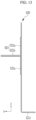
- FIG. 15 is a cross-sectional view schematically showing a side plate according to an eighth embodiment of the present disclosure.
- the same reference numerals as those in FIGS. 1 to 14 denote the same or similar members having the same or similar functions.
- detailed descriptions of the same reference numerals are omitted.
- the side plate 820 may have one side surface supporting side surfaces of the plurality of battery cells 111, and the side plate 820 may have an outer surface coupled to a bent flange 821 that is coupled to the frame portion 100.
- One side of the bent flange 821 may be coupled to a side surface of the side plate 820, and a portion of the bent flange 821 may protrude from the side surface of the side plate 820 in a state in which the portion of the bent flange is bent at an angle of approximately 90 degrees.
- the bent flange 821 may be detachably coupled to the frame portion 100 by a bolt member.
- a bonding bent portion 822 may be formed at a portion where the bent flange 821 is coupled to the side plate 820.
- an adhesive may be applied between the battery cell 111 and the bonding bent portion 822, so that the battery cell 111 and the side plate 820 may be bonded to each other.
- FIG. 16 is a cross-sectional view schematically showing a side plate according to a ninth embodiment of the present disclosure.
- the same reference numerals as those in FIGS. 1 to 15 denote the same or similar members having the same or similar functions.
- detailed descriptions of the same reference numerals are omitted.
- a first side portion 922 and a second side portion 924 may be welded and coupled to each other.
- the first side portion 922 may have one side surface supporting side surfaces of the plurality of battery cells 111, and the first side portion 922 may have an upper end edge of the first side portion 922 may include a first bent portion 922a bent outward.
- the bending support portion 121c may be bent at a lower portion of the first side portion 922 to support lower portions of the battery cells 111.
- the second side portion 924 may be coupled to an upper portion of the first side portion 922 and a lower end edge of the second side portion 924 may be bent outward.
- the second side portion 924 may include a second bent portion 924a coupled to the first bent portion 922a.
- the first bent portion 922a and the second bent portion 924a may be formed to have the same length and may be welded and coupled.
- the first and second bent portions 922a and 924a may protrude from one side of the side plate 920 to be coupled to the frame portion 100.
- the first bent portion 922a and the second bent portion 924a may include a plurality of screw holes (not shown) formed in a state in which the first bent portion 922a and the second bent portion 924a are welded.
- the first and second bent portions 922a and 924a may therefore be detachably coupled to the frame portion 100 by fastening members inserted into the screw holes.
- the first side portion 922 and the second side portion 924 may be formed by roll forming.
- FIG. 17 is a plan view schematically showing a battery module in a state in which a cutout portion is formed at a side plate according to a tenth embodiment of the present disclosure
- FIG. 18 is a main portion perspective view schematically showing a state in which the side plate with the cutout portion of FIG. 17 is installed.
- the same reference numerals as those in FIGS. 1 to 16 denote the same or similar members having the same or similar functions.
- detailed descriptions of the same reference numerals are omitted.
- cutout portions 1222 may be formed between a plurality of screw holes 121b in a bending portion 1221.
- the cutout portions 1222 may be cut in trapezoidal shapes between the plurality of screw holes 121b. But the cutout portions 1222 are not necessarily limited to a trapezoidal shape, and the cutout portions 122 may be changed to various polygonal shapes.
- a cut width of the cutout portions 1222 may be larger than a width of the bending portion 1221 in which the screw hole 121b is formed.
Landscapes
- Chemical & Material Sciences (AREA)
- Chemical Kinetics & Catalysis (AREA)
- Electrochemistry (AREA)
- General Chemical & Material Sciences (AREA)
- Engineering & Computer Science (AREA)
- Inorganic Chemistry (AREA)
- Aviation & Aerospace Engineering (AREA)
- Battery Mounting, Suspending (AREA)
- Manufacturing & Machinery (AREA)
Abstract
A battery pack includes a frame portion forming an accommodation space, a plurality of battery modules positioned in the accommodation space of the frame portion, a lower cover that covers a lower portion of the frame portion, and an upper cover that covers an upper portion of the frame portion. Each of the battery modules includes a plurality of battery cells, a plurality of side plates that include bent portions that are coupled to the frame portion and support side surfaces of the battery cells, and a plurality of end plates that connect ends of each of the side plates to each other.
Description
- The present disclosure relates to a battery pack with enhanced structural rigidity of a frame portion of a battery module.
- A secondary battery (or a rechargeable battery) is widely used in a mobile device, an auxiliary electric power device, or the like. In addition, secondary batteries are also attracting attention as a main power source for an electric vehicle, a hybrid electric vehicle, a plug-in hybrid electric vehicle, or the like, which are proposed as alternatives to conventional and diesel vehicles to solve various problems such as air pollution.
- In the electric vehicle or the like, a battery module in which a plurality of battery cells are stacked and then electrically connected in series and in parallel is used due to a need for a high-output and large-capacity battery. The battery cells are stacked in the battery module, and terminals exposed at both ends of each battery cell are electrically connected to provide a high voltage.
- A frame constituting an outer wall of the battery module uses aluminum and stainless steel (SUS) that can be welded and do not generate rust. A material of a side plate is determined according to a shape and a material of an end plate with a surface where a swelling force and a compression force required for assembly act in one direction according to a direction in which the battery cell is disposed. If the end plate and the side plate are made of different materials, a same material may be included inside the plate in a special case because welding does not reach a required strength.
- In a long battery module having a predetermined length or more, the battery module may have a flange shape protruding from a side surface thereof so as to be fixed to a frame portion of a battery pack at a plurality of positions. In the long battery module, the flange requires sufficient thickness and rigidity to fix the module with a relatively heavy volume.
- In accordance with the present invention a battery pack, as set forth in independent claim 1, is provided. Preferred embodiments of the invention are described in the dependent claims.
- Embodiments of the present disclosure provide a battery pack in which structural rigidity of a frame supporting battery cells of a battery module is strengthened and a space efficiency of a battery is improved by reducing a thickness when a battery module using roll forming is manufactured.
- A battery pack according to embodiments of the present disclosure includes: a frame portion forming an accommodation space; a plurality of battery modules positioned in the accommodation space of the frame portion; a lower cover that covers a lower portion of the frame portion; and an upper cover that covers an upper portion of the frame portion. Each of the battery modules includes: a plurality of battery cells; a plurality of side plates including bent portions that are coupled to the frame portion and support side surfaces of the plurality of battery cells; and a plurality of end plates that connect ends of the side plates to each other.
- Each of the side plates may include an inner surface that supports the side surfaces of the battery cells, and each of the side plates may be bent along an upper edge to form a folded portion that is in contact with a surface of the side plate.
- The folded portion may be welded to the surface of the side plate.
- An end portion of the folded portion may include a bent portion protruding from the side plate.
- Each of the bent portions may include a plurality of screw holes and a plurality of cutout portions may be formed between the plurality of screw holes, and fastening members may be inserted into the screw holes to fix the bent portion to the frame portions.
- The cutout portions may be formed in trapezoidal shapes.
- Each of the side plates may include bending support portion formed at a lower portion of the side plate that supports a lower surface of the battery module.
- Each of the side plates may be roll formed.
- An insulating film may be attached to a surface of the side plate facing the battery cells.
- Each of the side plates may include a side surface that supports the side surfaces of the battery cells, and the side surface may include a bent connection portion that is bent and protrudes in a direction away from the side surfaces of the battery cells.
- An avoiding bent portion may be formed at an upper edge of each of the side plates, with the avoiding bent portion being bent in the direction away from the side surfaces of the battery cells.
- A portion of one side surface of each of the side plates may be connected to the side surfaces of the battery cells using an adhesive, and each of the side plates may include an adhesive bent portion that is spaced apart from the side surfaces of the battery cells at a portion of the side plate where the adhesive is applied.
- Each of the side plates may include a first side surface that supports the side surfaces of the battery cells and a second side surface that is coupled to a connection flange coupled to the frame portion, and the connection flange may include a connection plate coupled to the second side surface of the side plate and a connection protruding portion protruding in a direction away from the side plate to be coupled to the frame portion.
- A portion of each of the side plates to which the connection plates may be coupled may be bent so that a bonding bent portion spaced apart from the side surfaces of the battery cells is formed.
- An adhesive may be applied between the bonding bent portion and the side surfaces of the battery cells.
- The side plates may include: a first side portion that includes a side surface supporting the side surfaces of the battery cells, wherein an upper end of the first side portion includes a first bent outward portion that is bent in a direction away from the battery cells; and a second side portion that is coupled to an upper end of the first side portion, wherein a lower end of the second side portion includes a second bent outward portion that is bent outward in the direction away from the battery cells and is coupled to the first bent outward portion.
- The first side portion and the second side portion may be roll formed.
- The battery pack may further include an insulating plate that includes a first end connected to a side surface of one of the end plates, a second end connected to a side surface of another one of the end plates, and side surfaces supporting the side surfaces of the battery cells.
- The insulating plate may include: a first insulating plate that includes ends connected to side surfaces of the end plates to support the side surfaces of the battery cells; and a second insulating plate that includes a portion welded to a side surface of the first insulating plate and ends connected to the side surfaces of the end plates to support the side surfaces of the battery cells.
- The first insulating plate may be bent along a lower edge thereof to form a first bending support portion supporting a lower surface of the battery module, and the second insulating plate may be bent along the lower edge thereof to form a second bending support portion supporting the lower surface of the battery module.
- A first upper bent portion may be formed at an upper portion of the first insulating plate and a first lower bent portion may be formed at a lower portion of the first insulating plate, a second upper bent portion may be formed at an upper portion of the second insulating plate and a second lower bent portion may be formed at a lower portion of the second insulating plate, and the first upper bent portion and the second upper bent portion may be welded to each other and the first lower bent portion and the second lower bent portion may be welded to each other.
- The first insulating plate and the second insulating plate may be roll formed.
- The side plates may be made of stainless steel.
- An insulating film may be attached to one or more inner surfaces of one or more of the side plates.
- According to the embodiments of the present disclosure, a side plate supporting a battery cell may be formed of a SUS material or a steel material and rigidity of a plate portion where a battery module is connected to a frame portion may be improved such that durability thereof is improved.
- According to the embodiments of the present disclosure, the side plate supporting the battery module may be manufactured using a roll forming method. Thus, it is possible to prevent increases in costs due to enlargement of a facility required for a battery module and thereby prevent increased facility investment costs.
-
-
FIG. 1 is a perspective view schematically showing a battery pack according to a first embodiment of the present disclosure. -
FIG. 2 is an exploded perspective view schematically showing the battery pack ofFIG. 1 . -
FIG. 3 is a perspective view schematically showing a battery module according to the first embodiment of the present disclosure. -
FIG. 4 is a perspective view schematically showing a state in which a side plate and end plates of the battery module ofFIG. 3 are coupled to each other. -
FIG. 5 is a perspective view schematically showing the side plate according to the first embodiment of the present disclosure. -
FIG. 6 is a main portion perspective view schematically showing a portion of the side plate ofFIG. 5 . -
FIG. 7 is a cross-sectional view schematically showing the side plate ofFIG. 5 . -
FIG. 8 is a cross-sectional view schematically showing an insulating plate according to the first embodiment of the present disclosure. -
FIG. 9 is a cross-sectional view schematically showing a side plate according to a second embodiment of the present disclosure. -
FIG. 10 is a cross-sectional view schematically showing a side plate according to a third embodiment of the present disclosure. -
FIG. 11 is a cross-sectional view schematically showing a side plate according to a fourth embodiment of the present disclosure. -
FIG. 12 is a cross-sectional view schematically showing a side plate according to a fifth embodiment of the present disclosure. -
FIG. 13 is a cross-sectional view schematically showing a side plate according to a sixth embodiment of the present disclosure. -
FIG. 14 is a cross-sectional view schematically showing a side plate according to a seventh embodiment of the present disclosure. -
FIG. 15 is a cross-sectional view schematically showing a side plate according to an eighth embodiment of the present disclosure. -
FIG. 16 is a cross-sectional view schematically showing a side plate according to a ninth embodiment of the present disclosure. -
FIG. 17 is a plan view schematically showing a battery module in a state in which a cutout portion is formed at a side plate according to a tenth embodiment of the present disclosure. -
FIG. 18 is a main portion perspective view schematically showing a state in which the side plate with the cutout portion ofFIG. 17 is installed. - Embodiments of the present disclosure will be described more fully hereinafter with reference to the accompanying drawings so that those skilled in the art easily implement the embodiments. The present disclosure may be modified in various different ways, all without departing from the spirit or scope of the present disclosure. In order to clearly describe the present disclosure, parts or portions that are irrelevant to the description are omitted in the drawings, and identical or similar constituent elements throughout the specification are denoted by the same reference numerals.
-
FIG. 1 is a perspective view schematically showing a battery pack according to a first embodiment of the present disclosure, andFIG. 2 is an exploded perspective view schematically showing the battery pack ofFIG. 1 . - As shown in
FIG. 1 andFIG. 2 , thebattery pack 300 according to the first embodiment of the present disclosure may include aframe portion 100 in which a plurality of frames are coupled to each other and an accommodation space is formed therein. A plurality ofbattery modules 200 are inserted into the accommodation space of theframe portion 100, alower cover 50 covers a lower portion of theframe portion 100, and anupper cover 60 covers an upper portion of theframe portion 100. - The
frame portion 100 may include afirst side frame 10 and asecond side frame 20. Afirst end frame 30 and asecond end frame 40 connect thefirst side frame 10 and thesecond side frame 20 to each other. Thefirst side frame 10 may be coupled to one edge of thelower cover 50, and may be installed to support one side of the plurality ofbattery modules 200. Thesecond side frame 20 may be coupled to the other edge of thelower cover 50 and may be installed to support the other side of the plurality ofbattery modules 200. - The
first end frame 30 may be installed to connect one end of thefirst side frame 10 and one end of thesecond side frame 20. For example, one end of thefirst end frame 30 may be connected to the one end of thefirst side frame 10 by afastening member 11, and the other end of thefirst end frame 30 may be connected to the one end of thesecond side frame 20 by thefastening member 11. - The
second end frame 40 may be installed to connect the other end of thefirst side frame 10 and the other end of thesecond side frame 20. For example, one end of thesecond end frame 40 may be connected to the other end of thefirst side frame 10 by thefastening member 11, and the other end of thesecond end frame 40 may be connected to the other end of thesecond side frame 20 by thefastening member 11. - The accommodation space may be formed inside the
frame portion 100 such that thebattery module 200 may be installed inside the accommodation space. Thelower cover 50 may be coupled to the lower portion of theframe portion 100 and theupper cover 60 may be coupled to the upper portion of theframe portion 100, so that abattery cell 111 accommodated inside theframe portion 100 is supported. -
FIG. 3 is a perspective view schematically showing the battery module according to the first embodiment of the present disclosure, andFIG. 4 is a perspective view schematically showing a state in which a side plate and end plates of the battery module ofFIG. 3 are coupled to each other. - As shown in
FIG. 3 andFIG. 4 , thebattery module 200 may include a plurality ofbattery cells 111, a plurality ofside plates 120 that support side surfaces of the plurality ofbattery cells 111 and are bent so that a portion of the side surface is coupled to theframe portion 100, and a plurality ofend plates 130 connecting both ends of each of the plurality ofside plates 120 to each other. The plurality ofside plates 120 may be installed to support the side surfaces of the plurality ofbattery cells 111. The plurality ofside plates 120 may include a first side plate and a second side plate that respectively support both opposing sides of the plurality ofbattery cells 111. In the first embodiment, the side plate, the first side plate, and the second side plate use thesame reference numeral 120. That is, the first andsecond side plates 120 may be installed with the same size and shape, and hereinafter, the first and second side plates use thesame reference numeral 120. - The
end plate 130 may be installed to connect both ends of each of the first andsecond side plates 120 to each other. The end plate may include first andsecond end plates 130. The first and second end plates may be installed with the same size and shape, and hereinafter, the first and second end plates use thesame reference numeral 130. - A portion of an edge of the
side plate 120 along a length direction may be folded in a direction of one side surface. Theside plate 120 may be installed to secure structural rigidity. In some embodiments, a portion of theside plate 120 may be folded to enable an overlapping configuration of the plate so that the structural rigidity is secured. In the present embodiment, theside plate 120 may be formed of a SUS material or a steel material. In the present embodiment, an insulatingplate 140 as shown inFIG. 4 may be installed at a position between rows of the plurality of battery modules 200 (further described below). -
FIG. 5 is a perspective view schematically showing the side plate according to the first embodiment of the present disclosure,FIG. 6 is a main portion perspective view schematically showing a portion of the side plate ofFIG. 5 , andFIG. 7 is a cross-sectional view schematically showing the side plate ofFIG. 5 . - Referring to
FIGS. 5 to 7 , theside plate 120 may have an inner surface that supports the side surfaces of the plurality ofbattery cells 111, and theside plate 120 may include afolding portion 121 that includes a portion folded along an upper edge to be in surface contact with an outer surface thereof. A portion of theside plate 120 may be bent so that thefolding portion 121 is formed, and thefolding portion 121 may be formed to increase a thickness of theside plate 120 along a width direction. Thefolding portion 121 may be formed to have a length corresponding to approximately half of a height direction (a z-axis direction) of theside plate 120. - A
bent portion 121a may protrude from an end portion of thefolding portion 121 so as to protrude in a side surface direction of theside plate 120. In particular, a portion of thefolding portion 121 formed outside theside plate 120 may be bent so that thebent portion 121a may protrude from the side plate. - The
side plate 120 at which thefolding portion 121 and thebent portion 121a may be formed by roll forming. In particular, the side plate made of a SUS material or a steel material may be processed by the roll forming. Thus, it is possible to prevent increased costs due to enlargement of a facility required for a part of a long battery module and prevent increased facility investment cost. - One reason why the
bent portion 121a protrudes from a side surface of theside plate 120 is to allow thebattery module 200 to be coupled to theframe portion 100 by a fastening member so that thebattery module 200 is stably fixed to theframe portion 100. To this end, a plurality ofbolt holes 121b may be formed in thebent portion 121a for coupling fastening members such as bolt members or the like. - A bending
support portion 121c may be formed at a lower portion of theside plate 120. The bendingsupport portion 121c may be bent at a lower edge of theside plate 120, and may be formed at the lower portion of theside plate 120 to support a lower portion of thebattery cell 111. - Thus, the
battery cell 111 may be stably fixed in a state in which thebattery cell 111 is accommodated inside theframe portion 100. - As shown in
FIG. 7 , an insulatingfilm 123 may be attached to a side surface of theside plate 120 contacting thebattery cell 111. A portion of the insulatingfilm 123 may protrude upward from theside plate 120 in a state in which it is attached to an entire surface where thebattery cell 111 is in contact with theside plate 120. - A pair of the
side plates 120 may be connected to each other by a pair of theend plates 130. The plurality ofbattery modules 200 may be inserted into theframe portion 100, and the plurality ofbattery modules 200 may be disposed in two rows. While the present embodiment describes the plurality ofbattery modules 200 as being disposed in two rows inserted into theframe portion 100, the present disclosure is not necessarily limited thereto. For example, thebattery module 200 may be inserted as a single row in theframe portion 100 in a state in which the insulating plate 140 (described below) is removed. - The insulating
plate 140 may be installed at a position between rows of the plurality ofbattery modules 200. Both ends of the insulatingplate 140 may be connected to the pair ofend plates 130 at a position between the pair ofside plates 120. -
FIG. 8 is a cross-sectional view schematically showing the insulating plate according to the first embodiment of the present disclosure. - As shown in
FIG. 8 , the insulatingplate 140 may include first and second insulatingplates plates end plates 130. The first and second insulatingplates plates end plates 130. - The insulating
plate 140 may include the first insulatingplate 141 that has both of its ends connected to side surfaces of the plurality ofend plates 130 to support the side surfaces of the plurality of battery cells. The second insulatingplate 143 that has a portion welded to a side surface of the first insulatingplate 141 and has both ends connected to the side surfaces of the plurality ofend plates 130 to support the side surfaces of the plurality of battery cells. - The first insulating
plate 141 may be installed to support side surfaces of the plurality ofbattery cells 111 disposed in a first row among thebattery cells 111 that are disposed in two rows. A portion of the first insulatingplate 141 along a length direction may be formed to be bent in a state in which both ends of the first insulatingplate 141 are connected to the pair ofend plates 130. One reason why the portion of the first insulatingplate 141 along the length direction is bent is to couple the bent portion to the second insulatingplate 143 by contacting the bent portion with the second insulatingplate 143. Another reason why the portion of the first insulatingplate 141 along the length direction is bent is to apply an adhesive to a space formed between the bent portion of the first insulatingplate 141 and side surfaces of thebattery cells 111. - In some embodiments, a side surface of the first insulating
plate 141 may support the side surfaces of thebattery cells 111, a first upperbent portion 141a may be formed at an upper portion of the first insulatingplate 141, and a first lowerbent portion 141b may be formed at a lower portion of the first insulatingplate 141. The first upperbent portion 141a and the first lowerbent portion 141b may be bent so that a space is formed between the first upperbent portion 141a and the first lowerbent portion 141b and the side surface of thebattery cell 111. - The second insulating
plate 143 may be installed to support side surfaces of the plurality ofbattery cells 111 disposed in a second row among thebattery cells 111 that are disposed in two rows. A portion of the second insulatingplate 143 along a length direction may be formed to be bent in a state in which both ends of the second insulatingplate 143 are connected to the pair ofend plates 130. - A side surface of the second insulating
plate 143 may support the side surfaces of thebattery cells 111, a second upperbent portion 143a may be formed at an upper portion of the second insulatingplate 143, and a second lowerbent portion 143b may be formed at a lower portion of the second insulatingplate 143. - In a state in which the first insulating
plate 141 and the second insulatingplate 143 are disposed adjacent to each other, the first and second upperbent portions bent portions bent portions bent portions - Each of the first and second upper
bent portions bent portions plates battery cells 111. Thus, welding heat may not be transferred to the side surfaces of the first and second insulatingplates bent portions bent portions plates - A first
bending support portion 141c that supports a lower surface of the battery module may be formed at a lower portion of the first insulatingplate 141. In some embodiments, a secondbending support portion 143c that supports the lower surface of the battery module may be formed at a lower portion of the second insulatingplate 143. The firstbending support portion 141c and the secondbending support portion 143c may protrude in opposite directions and be formed to support lower portions of thebattery cells 111 in different rows. - The insulating
film 123 may be attached to the side surfaces of the first and second insulatingplates - As described above, in the
battery pack 300 of the present embodiment, theside plate 120 supporting thebattery cells 111 may be formed of a SUS material or a steel material and rigidity of a plate portion where thebattery module 200 is connected to theframe portion 100 may be further improved, so that durability thereof is improved. Further, because theside plate 120 is manufactured using a roll forming method, a facility required for manufacturing the battery pack may be minimized so that a manufacturing cost is minimized. -
FIG. 9 is a cross-sectional view schematically showing a side plate according to a second embodiment of the present disclosure. In the following description, the same reference numerals as those inFIGS. 1 to 8 denote the same or similar member features having the same or similar function. Thus, detailed descriptions of the same reference numerals for each of other embodiments described below will be omitted. - As shown in
FIG. 9 , theside plate 220 according to the second embodiment of the present disclosure may have one side surface supporting side surfaces of the plurality ofbattery cells 111, and theside plate 220 may include abent connection portion 221 protruding in a direction of the other side surface by bending a portion of a side surface of theside plate 220. Thebent connection portion 221 may have a portion between an upper edge and a lower edge of theside plate 220 and protrude outward. Thebent connection portion 221 may protrude in an outer direction of theside plate 220 in an approximate flange shape without welding. Thebent connection portion 221 may protrude outward such that a portion of theside plate 220 is overlapped, and thebent connection portion 221 may protrude to have a thickness approximately twice or more that of theside plate 220. - A plurality of screw holes (not shown) may be formed at the
bent connection portion 221. Fastening members such as a bolt members or the like may be inserted to the screw holes to fix the bent connection portion to theframe portion 100 shown inFIG. 2 . - The bending
support portion 121c may be formed at a lower portion of thebent connection portion 221. The bendingsupport portion 121c may be formed at a lower edge of theside plate 220. That is, the bendingsupport portion 121c may be formed at a lower portion of theside plate 220 to support lower portions of thebattery cells 111. - The
side plate 220 in which thebent connection portion 221 and the bendingsupport portion 121c are formed may be formed by roll forming. A height of theside plate 220 may be determined depending on heights of the battery cells. Further, a height of thebent connection portion 221 may be determined according to a height of a bolt member that is fastened to theframe portion 100. In some embodiments, a protruding length of thebent connection portion 221 may be determined depending on a size of a head portion of the bolt member. - An insulating film (not shown) may be attached to a surface of the
side plate 220 contacting thebattery cells 111. - As described above, the
side plate 220 of the second embodiment of the present disclosure may be more stably fixed to theframe portion 100 by two-layer overlapping protruding shapes of thebent connection portion 221. Thus, durability of theside plate 220 is improved. -
FIG. 10 is a cross-sectional view schematically showing a side plate according to a third embodiment of the present disclosure. In the following description, the same reference numerals as those inFIGS. 1 to 9 denote the same or similar members having the same or similar functions. Hereinafter, detailed descriptions of the same reference numerals are omitted. - As shown in
FIG. 10 , an avoidingbent portion 321 that is bent in a direction of thebent connection portion 221 may be formed at an upper edge of aside plate 320 of the third embodiment. The avoidingbent portion 321 may be formed to be bent outside the side plate 320 (that is, in a side surface direction in which thebent connection portion 221 is connected). - The avoiding
bent portion 321 may be formed by bending a portion of the upper edge of theside plate 320 in an outer direction of theside plate 320. The avoidingbent portion 321 may prevent a damage caused by an insulating film (not shown) attached to an inner surface of theside plate 320 interfering with an upper edge portion of theside plate 320. -
FIG. 11 is a cross-sectional view schematically showing a side plate according to a fourth embodiment of the present disclosure. In the following description, the same reference numerals as those inFIGS. 1 to 10 denote the same or similar members having the same or similar functions. Hereinafter, detailed descriptions of the same reference numerals are omitted. - As shown in
FIG. 11 , theside plate 420 according to the fourth embodiment may include a foldedportion 421 in which a portion of an upper edge of theside plate 420 is folded in an outer direction of theside plate 420. The foldedportion 421 of the fourth embodiment may prevent damage caused by an insulating film (not shown) attached to an inner surface of theside plate 420 interfering with an upper edge portion of theside plate 420. -
FIG. 12 is a cross-sectional view schematically showing a side plate according to a fifth embodiment of the present disclosure. In the following description, the same reference numerals as those inFIGS. 1 to 11 denote the same or similar members having the same or similar functions. Hereinafter, detailed descriptions of the same reference numerals are omitted. - As shown in
FIG. 12 , a portion of one side surface of theside plate 520 according to the fifth embodiment of the present disclosure may be connected to side surfaces of the plurality of battery cells by an adhesive (not shown). To this end, an adhesivebent portion 521 bent may be formed at a portion of theside plate 520 where the adhesive is applied. The adhesivebent portion 521 refers to a portion of theside plate 520 that is bent outward to form a space where the adhesive is applied between the adhesivebent portion 521 and side surfaces of thebattery cells 111. The adhesivebent portion 521 may be formed at a lower portion where the bendingsupport portion 121c is connected and below where thebent connection portion 221 is formed. - Because the adhesive is applied to the adhesive
bent portion 521, theside plate 520 may be stably fixed to thebattery cells 111 to stably support thebattery cells 111 in an insulating state. The adhesive may be applied to an upper portion, a lower portion, and a middle portion of theside plate 520 and to the adhesivebent portion 521 to thereby provide stable adhesive fixation of theside plate 520 to thebattery cells 111. The adhesive may be a structural adhesive, may be a fast-curing polyurethane type adhesive, and may be applied to a surface of the adhesivebent portion 521 at a thickness of 0.2 mm to 1 mm. - The
side plate 520 at which the adhesivebent portion 521 is formed may be formed by roll forming. -
FIG. 13 is a cross-sectional view schematically showing a side plate according to a sixth embodiment of the present disclosure. In the following description, the same reference numerals as those inFIGS. 1 to 12 denote the same or similar members having the same or similar functions. Hereinafter, detailed descriptions of the same reference numerals are omitted. - As shown in
FIG. 13 , theside plate 620 according to the sixth embodiment of the present disclosure may have one side surface supporting side surfaces of the plurality ofbattery cells 111, and theside plate 620 may have an outer surface coupled to aconnection flange 621 that is coupled to theframe portion 100. - The
connection flange 621 may protrude from theside plate 620 and be in surface contact with an outer side surface of theside plate 620. Further, theconnection flange 621 may be detachably coupled to theframe portion 100 by a fastening member. - The
connection flange 621 may include aconnection plate 621a coupled to the outer surface of theside plate 620, and aconnection protruding portion 621b protruding to outside of theconnection plate 621a to be connected to theframe portion 100. Theconnection plate 621a may be welded in a state in which the connection plate is in surface contact with the side surface of theside plate 620. That is, theconnection plate 621a may be welded to a portion of the side surface of theside plate 620. - With the
connection protruding portion 621b protruding from the side surface of theconnection plate 621a, and a plurality of screw holes (not shown) may be formed so that the connection protruding portion may be detachably coupled to theframe portion 100 by a bolt member. - The
side plate 620 may be formed by roll forming. -
FIG. 14 is a cross-sectional view schematically showing a side plate according to a seventh embodiment of the present disclosure. In the following description, the same reference numerals as those inFIGS. 1 to 13 denote the same or similar members having the same or similar functions. Hereinafter, detailed descriptions of the same reference numeral are omitted. - As shown in
FIG. 14 , in theside plate 720 according to the seventh embodiment of the present disclosure, a portion of the side plate to which theconnection plate 621a is coupled may be bent so that a bondingbent portion 721 spaced apart from an outer surface of the battery cell is formed. The bondingbent portion 721 may form a space in which an adhesive may be applied between the bondingbent portion 721 and outer surfaces of thebattery cells 111 so that it is possible to stably support thebattery cells 111 in an insulating state using theside plate 720. - The
side plate 120 at which the bondingbent portion 721 is formed may be formed by roll forming. -
FIG. 15 is a cross-sectional view schematically showing a side plate according to an eighth embodiment of the present disclosure. In the following description, the same reference numerals as those inFIGS. 1 to 14 denote the same or similar members having the same or similar functions. Hereinafter, detailed descriptions of the same reference numerals are omitted. - As shown in
FIG. 15 , theside plate 820 according to the eighth embodiment of the present disclosure may have one side surface supporting side surfaces of the plurality ofbattery cells 111, and theside plate 820 may have an outer surface coupled to abent flange 821 that is coupled to theframe portion 100. - One side of the
bent flange 821 may be coupled to a side surface of theside plate 820, and a portion of thebent flange 821 may protrude from the side surface of theside plate 820 in a state in which the portion of the bent flange is bent at an angle of approximately 90 degrees. Thebent flange 821 may be detachably coupled to theframe portion 100 by a bolt member. A bondingbent portion 822 may be formed at a portion where thebent flange 821 is coupled to theside plate 820. Thus, an adhesive may be applied between thebattery cell 111 and the bondingbent portion 822, so that thebattery cell 111 and theside plate 820 may be bonded to each other. -
FIG. 16 is a cross-sectional view schematically showing a side plate according to a ninth embodiment of the present disclosure. In the following description, the same reference numerals as those inFIGS. 1 to 15 denote the same or similar members having the same or similar functions. Hereinafter, detailed descriptions of the same reference numerals are omitted. - As shown in
FIG. 16 , in theside plate 920 according to the ninth embodiment of the present disclosure, afirst side portion 922 and asecond side portion 924 may be welded and coupled to each other. Thefirst side portion 922 may have one side surface supporting side surfaces of the plurality ofbattery cells 111, and thefirst side portion 922 may have an upper end edge of thefirst side portion 922 may include a firstbent portion 922a bent outward. The bendingsupport portion 121c may be bent at a lower portion of thefirst side portion 922 to support lower portions of thebattery cells 111. - The
second side portion 924 may be coupled to an upper portion of thefirst side portion 922 and a lower end edge of thesecond side portion 924 may be bent outward. Thesecond side portion 924 may include a secondbent portion 924a coupled to the firstbent portion 922a. - The first
bent portion 922a and the secondbent portion 924a may be formed to have the same length and may be welded and coupled. The first and secondbent portions side plate 920 to be coupled to theframe portion 100. To this end, the firstbent portion 922a and the secondbent portion 924a may include a plurality of screw holes (not shown) formed in a state in which the firstbent portion 922a and the secondbent portion 924a are welded. The first and secondbent portions frame portion 100 by fastening members inserted into the screw holes. - The
first side portion 922 and thesecond side portion 924 may be formed by roll forming. -
FIG. 17 is a plan view schematically showing a battery module in a state in which a cutout portion is formed at a side plate according to a tenth embodiment of the present disclosure, andFIG. 18 is a main portion perspective view schematically showing a state in which the side plate with the cutout portion ofFIG. 17 is installed. In the following description, the same reference numerals as those inFIGS. 1 to 16 denote the same or similar members having the same or similar functions. Hereinafter, detailed descriptions of the same reference numerals are omitted. - As shown in
FIG. 17 andFIG. 18 , in theside plate 1220 of thebattery module 1300 according to the tenth embodiment of the present disclosure,cutout portions 1222 may be formed between a plurality of screw holes 121b in abending portion 1221. - The
cutout portions 1222 may be cut in trapezoidal shapes between the plurality ofscrew holes 121b. But thecutout portions 1222 are not necessarily limited to a trapezoidal shape, and the cutout portions 122 may be changed to various polygonal shapes. - A cut width of the
cutout portions 1222 may be larger than a width of the bendingportion 1221 in which thescrew hole 121b is formed. Thus, if a pair ofbattery modules 1300 are disposed inside theframe portion 100 as shown inFIG. 17 , pairs of bendingportions 1221 adjacent to each other may be disposed in a state in which the pairs of bending portions spaced between a plurality ofcutout portions 1222. Accordingly, in the pair ofbattery modules 1300, a plurality of bendingportions 1221 may be inserted into the plurality ofcutout portions 1222 in a zigzag disposition. Thus, it is possible to optimize an installation space by minimizing a separation distance between the pair ofbattery modules 1300. - While this disclosure has been described in connection with what is presently considered to be practical embodiments, it is to be understood that the disclosure is not limited to the disclosed embodiments. On the contrary, the disclosure is intended to cover various modifications and equivalent arrangements included within the scope of the appended claims.
-
- 10: first side frame; 11: fastening member;
- 20: second side frame; 30: first end frame;
- 40: second end frame; 50: lower cover;
- 60: upper cover; 100: frame portion;
- 111: battery cell; 120: side plate;
- 121: folding portion; 121a: bending portion;
- 121b: bolt hole; 121c: bending support portion;
- 123: insulating film; 130: end plate;
- 140: insulating plate; 141: first insulating plate;
- 141a: first upper bent portion; 141b: first lower bent portion;
- 141c: first bending support portion; 143: second insulating plate;
- 143a: second upper bent portion; 143b: second lower bent portion;
- 143c: second bending support portion; 200: battery module;
- 220: side plate;
- 221: bent connection portion; 300: battery pack; 320: side plate;
- 321: avoiding bent portion; 420: side plate;
- 421: folded portion; 520: side plate;
- 521: adhesive bent portion; 620: side plate;
- 621: connection flange; 720: side plate;
- 721: bonding bent portion; 820: side plate;
- 821: bent flange; 920: side plate;
- 922: first side portion; 922a: first bent portion;
- 924: second side portion; 924a: second bent portion;
- 1220: side plate;
- 1221: bending portion; 1222: cutout portion;
- 1300: battery module;
Claims (15)
- A battery pack (300) comprising:a frame portion (100) forming an accommodation space;a plurality of battery modules (200, 1300) positioned in the accommodation space of the frame portion (100);a lower cover (50) that covers a lower portion of the frame portion (100); andan upper cover (60) that covers an upper portion of the frame portion (100),wherein each of the battery modules (200, 1300) comprises:a plurality of battery cells (111);a plurality of side plates (120, 220, 320, 420, 520, 620, 720, 820, 920, 1220) including bent portions that are coupled to the frame portion (100) and support side surfaces of the battery cells (111); anda plurality of end plates (130) that connect ends of the side plates to each other.
- The battery pack (300) as claimed in claim 1, wherein each of the side plates includes an inner surface that supports the side surfaces of the of battery cells (111), and each of the side plates is bent along an upper edge to form a folded portion (121, 421) that is in contact with a surface of the side plate.
- The battery pack (300) as claimed in claim 2, wherein an end portion of the folded portion includes a bent portion (121a) protruding from the side plate.
- The battery pack as claimed in claim 3, wherein each of the bent portions includes a plurality of screw holes (121b) and a plurality of cutout portions (1222) are formed between the plurality of screw holes, andwherein fastening members are inserted into the screw holes to fix the bent portion to the frame portion (100); and, optionally,wherein the cutout portions are formed in trapezoidal shapes.
- The battery pack (300) as claimed in any one of claims 1 to 4, wherein each of the side plates includes a bending support portion (121c) formed at a lower portion of the side plate that supports a lower surface of the battery module (200, 1300); and, optionally,
wherein each of the side plates is roll formed. - The battery pack (300) as claimed in claim 1, wherein each of the side plates includes a side surface that supports the side surfaces of the battery cells (111) and the side surface includes a bent connection portion (221) that is bent and protrudes in a direction away from the side surfaces of the battery cells (111); and, optionally,
wherein an avoiding bent portion (321) is formed at an upper edge of each of the side plates, with the avoiding bent portion being bent in the direction away from the side surfaces of the battery cells (111). - The battery pack (300) as claimed in claim 1, wherein a portion of one side surface of each of the side plates is connected to the side surfaces of the battery cells (111) using an adhesive, and
wherein each of the side plates includes an adhesive bent portion (521) that is spaced apart from the side surfaces of the battery cells (111) at a portion of the side plate where the adhesive is applied. - The battery pack (300) as claimed in claim 1, wherein each of the side plates includes a first side surface that supports the side surfaces of the battery cells (111) and a second side surface that is coupled to a connection flange (621) coupled to the frame portion (100), and
wherein the connection flange includes a connection plate (621a) coupled to the second side surface of the side plate and a connection protruding portion (621b) protruding in a direction away from the side plate to be coupled to the frame portion (100). - The battery pack (300) as claimed in claim 8, wherein a portion of each of the side plates to which the connection plates are coupled is bent so that a bonding bent portion (721) spaced apart from the side surfaces of the battery cells (111) is formed; and
wherein an adhesive is applied between the bonding bent portion (721) and the side surfaces of the battery cells (111). - The battery pack (300) as claimed in claim 1, wherein each of the side plates comprises:a first side portion (922) that includes a side surface supporting the side surfaces of the battery cells (111), wherein an upper end of the first side portion includes a first bent outward portion (922a) that is bent in a direction away from the battery cells (111); anda second side portion (924) that is coupled to an upper end of the first side portion, wherein a lower end of the second side portion includes a second bent outward portion (924a) that is bent outward in the direction away from the battery cells (111) and is coupled to the first bent outward portion; and, optionally,wherein the first side portion and the second side portion are roll formed.
- The battery pack (300) as claimed in any one of claims 1 to 10, further comprising an insulating plate (140) that includes a first end connected to a side surface of one of the end plates (130), a second end connected to a side surface of another of the end plates (130), and side surfaces supporting the side surfaces of the battery cells (111).
- The battery pack (300) as claimed in claim 11, wherein the insulating plate comprises:a first insulating plate (141) that includes ends connected to side surfaces of the end plates (130) to support the side surfaces of the battery cells (111); anda second insulating plate (143) that includes a portion welded to a side surface of the first insulating plate and ends connected to the side surfaces of the end plates (130) to support the side surfaces of the battery cells (111).
- The battery pack (300) as claimed in claim 12, wherein the first insulating plate is bent along a lower edge thereof to form a first bending support portion (121c) supporting a lower surface of the battery module (200, 1300), and the second insulating plate is bent along the lower edge thereof to form a second bending support portion (143c) supporting the lower surface of the battery module (200, 1300).
- The battery pack (300) as claimed in claim 13, wherein a first upper bent portion (141a) is formed at an upper portion of the first insulating plate (141) and a first lower bent portion (141b) is formed at a lower portion of the first insulating plate (141), a second upper bent portion (143a) is formed at an upper portion of the second insulating plate (143) and a second lower bent portion (143b) is formed at a lower portion of the second insulating plate (143), and
wherein the first upper bent portion (141a) and the second upper bent (143a) portion are welded to each other and the first lower bent portion (141b) and the second lower bent portion (143b) are welded to each other. - The battery pack (300) as claimed in any one of claims 1 to 14, wherein an insulating film (123) is attached to an inner surface of each of the side plates.
Applications Claiming Priority (1)
| Application Number | Priority Date | Filing Date | Title |
|---|---|---|---|
| KR1020230166925A KR20250079585A (en) | 2023-11-27 | 2023-11-27 | Battery pack |
Publications (1)
| Publication Number | Publication Date |
|---|---|
| EP4567982A1 true EP4567982A1 (en) | 2025-06-11 |
Family
ID=93432142
Family Applications (1)
| Application Number | Title | Priority Date | Filing Date |
|---|---|---|---|
| EP24211222.5A Pending EP4567982A1 (en) | 2023-11-27 | 2024-11-06 | Battery pack |
Country Status (4)
| Country | Link |
|---|---|
| US (1) | US20250174790A1 (en) |
| EP (1) | EP4567982A1 (en) |
| KR (1) | KR20250079585A (en) |
| CN (1) | CN120049092A (en) |
Citations (4)
| Publication number | Priority date | Publication date | Assignee | Title |
|---|---|---|---|---|
| EP2339664A1 (en) * | 2009-12-23 | 2011-06-29 | SB LiMotive Co., Ltd. | Battery pack |
| DE102018120466A1 (en) * | 2018-08-22 | 2020-02-27 | GEDIA Gebrüder Dingerkus GmbH | Housing with a cuboid shape |
| US20200099027A1 (en) * | 2017-06-22 | 2020-03-26 | Sanyo Electric Co., Ltd. | Power supply device, vehicle equipped with same, and electricity storage device |
| EP3654401A1 (en) * | 2018-11-15 | 2020-05-20 | Contemporary Amperex Technology Co., Limited | Side plate and battery module |
-
2023
- 2023-11-27 KR KR1020230166925A patent/KR20250079585A/en active Pending
-
2024
- 2024-09-13 US US18/884,322 patent/US20250174790A1/en active Pending
- 2024-10-31 CN CN202411540821.4A patent/CN120049092A/en active Pending
- 2024-11-06 EP EP24211222.5A patent/EP4567982A1/en active Pending
Patent Citations (4)
| Publication number | Priority date | Publication date | Assignee | Title |
|---|---|---|---|---|
| EP2339664A1 (en) * | 2009-12-23 | 2011-06-29 | SB LiMotive Co., Ltd. | Battery pack |
| US20200099027A1 (en) * | 2017-06-22 | 2020-03-26 | Sanyo Electric Co., Ltd. | Power supply device, vehicle equipped with same, and electricity storage device |
| DE102018120466A1 (en) * | 2018-08-22 | 2020-02-27 | GEDIA Gebrüder Dingerkus GmbH | Housing with a cuboid shape |
| EP3654401A1 (en) * | 2018-11-15 | 2020-05-20 | Contemporary Amperex Technology Co., Limited | Side plate and battery module |
Also Published As
| Publication number | Publication date |
|---|---|
| CN120049092A (en) | 2025-05-27 |
| KR20250079585A (en) | 2025-06-04 |
| US20250174790A1 (en) | 2025-05-29 |
Similar Documents
| Publication | Publication Date | Title |
|---|---|---|
| US11309593B2 (en) | Flexible circuit board and frame assembly including same | |
| US8859131B2 (en) | Battery module and battery pack including the same | |
| US11264669B2 (en) | Battery box and battery module | |
| US8956751B2 (en) | Battery pack and battery module having the same | |
| EP2201629B1 (en) | Module pack for secondary battery | |
| KR101201747B1 (en) | Battery module | |
| JP4515961B2 (en) | Battery module using secondary battery | |
| JP5271334B2 (en) | Battery module and battery pack | |
| KR101117686B1 (en) | Battery module and battery pack having the same | |
| EP3151307A1 (en) | Battery module and battery pack comprising same | |
| US20150140405A1 (en) | Electricity storage module | |
| CN104425781A (en) | Battery pack | |
| EP3154108A1 (en) | Battery module and battery pack including same | |
| US20220123415A1 (en) | Method for Manufacturing Battery Module | |
| CN111725446A (en) | A battery module and battery pack | |
| US20210408640A1 (en) | Battery pack including connection plate, electronic device and vehicle | |
| JP2018506828A (en) | Battery compression blocker and battery module including the same | |
| KR101104151B1 (en) | Apparatus including plate reinforcement members | |
| EP2490277B1 (en) | Battery Module | |
| KR101435441B1 (en) | Battery Pack Having Battery Module Arrangements Fixed by Supporting Members and Connection Members | |
| JP2006140023A (en) | Assembled battery | |
| EP4567982A1 (en) | Battery pack | |
| CN209993632U (en) | A battery module and battery pack | |
| EP4123817B1 (en) | Fixing member, battery and method for manufacturing battery | |
| KR100684762B1 (en) | Secondary battery module and unit cell fixing plate |
Legal Events
| Date | Code | Title | Description |
|---|---|---|---|
| PUAI | Public reference made under article 153(3) epc to a published international application that has entered the european phase |
Free format text: ORIGINAL CODE: 0009012 |
|
| STAA | Information on the status of an ep patent application or granted ep patent |
Free format text: STATUS: REQUEST FOR EXAMINATION WAS MADE |
|
| 17P | Request for examination filed |
Effective date: 20241106 |
|
| AK | Designated contracting states |
Kind code of ref document: A1 Designated state(s): AL AT BE BG CH CY CZ DE DK EE ES FI FR GB GR HR HU IE IS IT LI LT LU LV MC ME MK MT NL NO PL PT RO RS SE SI SK SM TR |