EP4567981A1 - Battery pack - Google Patents
Battery pack Download PDFInfo
- Publication number
- EP4567981A1 EP4567981A1 EP23850116.7A EP23850116A EP4567981A1 EP 4567981 A1 EP4567981 A1 EP 4567981A1 EP 23850116 A EP23850116 A EP 23850116A EP 4567981 A1 EP4567981 A1 EP 4567981A1
- Authority
- EP
- European Patent Office
- Prior art keywords
- space
- mounting part
- seal material
- battery pack
- side frame
- Prior art date
- Legal status (The legal status is an assumption and is not a legal conclusion. Google has not performed a legal analysis and makes no representation as to the accuracy of the status listed.)
- Pending
Links
Images



Classifications
-
- H—ELECTRICITY
- H01—ELECTRIC ELEMENTS
- H01M—PROCESSES OR MEANS, e.g. BATTERIES, FOR THE DIRECT CONVERSION OF CHEMICAL ENERGY INTO ELECTRICAL ENERGY
- H01M50/00—Constructional details or processes of manufacture of the non-active parts of electrochemical cells other than fuel cells, e.g. hybrid cells
- H01M50/20—Mountings; Secondary casings or frames; Racks, modules or packs; Suspension devices; Shock absorbers; Transport or carrying devices; Holders
- H01M50/204—Racks, modules or packs for multiple batteries or multiple cells
-
- H—ELECTRICITY
- H01—ELECTRIC ELEMENTS
- H01M—PROCESSES OR MEANS, e.g. BATTERIES, FOR THE DIRECT CONVERSION OF CHEMICAL ENERGY INTO ELECTRICAL ENERGY
- H01M50/00—Constructional details or processes of manufacture of the non-active parts of electrochemical cells other than fuel cells, e.g. hybrid cells
- H01M50/20—Mountings; Secondary casings or frames; Racks, modules or packs; Suspension devices; Shock absorbers; Transport or carrying devices; Holders
- H01M50/244—Secondary casings; Racks; Suspension devices; Carrying devices; Holders characterised by their mounting method
-
- H—ELECTRICITY
- H01—ELECTRIC ELEMENTS
- H01M—PROCESSES OR MEANS, e.g. BATTERIES, FOR THE DIRECT CONVERSION OF CHEMICAL ENERGY INTO ELECTRICAL ENERGY
- H01M50/00—Constructional details or processes of manufacture of the non-active parts of electrochemical cells other than fuel cells, e.g. hybrid cells
- H01M50/20—Mountings; Secondary casings or frames; Racks, modules or packs; Suspension devices; Shock absorbers; Transport or carrying devices; Holders
- H01M50/262—Mountings; Secondary casings or frames; Racks, modules or packs; Suspension devices; Shock absorbers; Transport or carrying devices; Holders with fastening means, e.g. locks
-
- H—ELECTRICITY
- H01—ELECTRIC ELEMENTS
- H01M—PROCESSES OR MEANS, e.g. BATTERIES, FOR THE DIRECT CONVERSION OF CHEMICAL ENERGY INTO ELECTRICAL ENERGY
- H01M50/00—Constructional details or processes of manufacture of the non-active parts of electrochemical cells other than fuel cells, e.g. hybrid cells
- H01M50/20—Mountings; Secondary casings or frames; Racks, modules or packs; Suspension devices; Shock absorbers; Transport or carrying devices; Holders
- H01M50/271—Lids or covers for the racks or secondary casings
-
- H—ELECTRICITY
- H01—ELECTRIC ELEMENTS
- H01M—PROCESSES OR MEANS, e.g. BATTERIES, FOR THE DIRECT CONVERSION OF CHEMICAL ENERGY INTO ELECTRICAL ENERGY
- H01M50/00—Constructional details or processes of manufacture of the non-active parts of electrochemical cells other than fuel cells, e.g. hybrid cells
- H01M50/30—Arrangements for facilitating escape of gases
- H01M50/35—Gas exhaust passages comprising elongated, tortuous or labyrinth-shaped exhaust passages
- H01M50/358—External gas exhaust passages located on the battery cover or case
-
- H—ELECTRICITY
- H01—ELECTRIC ELEMENTS
- H01M—PROCESSES OR MEANS, e.g. BATTERIES, FOR THE DIRECT CONVERSION OF CHEMICAL ENERGY INTO ELECTRICAL ENERGY
- H01M50/00—Constructional details or processes of manufacture of the non-active parts of electrochemical cells other than fuel cells, e.g. hybrid cells
- H01M50/20—Mountings; Secondary casings or frames; Racks, modules or packs; Suspension devices; Shock absorbers; Transport or carrying devices; Holders
- H01M50/249—Mountings; Secondary casings or frames; Racks, modules or packs; Suspension devices; Shock absorbers; Transport or carrying devices; Holders specially adapted for aircraft or vehicles, e.g. cars or trains
-
- Y—GENERAL TAGGING OF NEW TECHNOLOGICAL DEVELOPMENTS; GENERAL TAGGING OF CROSS-SECTIONAL TECHNOLOGIES SPANNING OVER SEVERAL SECTIONS OF THE IPC; TECHNICAL SUBJECTS COVERED BY FORMER USPC CROSS-REFERENCE ART COLLECTIONS [XRACs] AND DIGESTS
- Y02—TECHNOLOGIES OR APPLICATIONS FOR MITIGATION OR ADAPTATION AGAINST CLIMATE CHANGE
- Y02E—REDUCTION OF GREENHOUSE GAS [GHG] EMISSIONS, RELATED TO ENERGY GENERATION, TRANSMISSION OR DISTRIBUTION
- Y02E60/00—Enabling technologies; Technologies with a potential or indirect contribution to GHG emissions mitigation
- Y02E60/10—Energy storage using batteries
Definitions
- the present invention relates to a battery pack.
- a battery pack includes at least one battery module and an accommodating body in which the at least one module is accommodated.
- Patent Literature 1 describes an example of a battery pack.
- the accommodating body includes a tray member and a lid member.
- the tray member and the lid member are fastened to each other by a fastening member via a gasket member.
- Patent Literature 1 Japanese Patent Application Laid-Open No. 2014-175123
- the accommodating body may include two mounting parts opposed to each other via a seal material. These two fastening parts may be fastened to each other by a fastener. In this case, improvement in sealing performance of an accommodating space of the accommodating body may be required. To improve sealing performance of the accommodating space, it is preferable to accurately adjust a thickness of the seal material. However, if the seal material is simply disposed, it may be difficult to accurately adjust the thickness of the seal material.
- An example of an objective of the present invention is to improve sealing performance of the accommodating space of the accommodating body.
- Other objectives of the present invention will become apparent from the description in this specification.
- An aspect of the present invention is as follows.
- sealing performance of the accommodating space of the accommodating body can be improved.
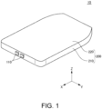
- FIG. 1 is a perspective view of a battery pack 10 according to the embodiment.
- FIG. 2 is a plan view of the battery pack 10 according to the embodiment with an upper case 220 removed.
- the battery pack 10 is mounted in an automobile. Specifically, the battery pack 10 is mounted between front wheels and rear wheels of the automobile.
- the battery pack 10 is mounted in an automobile.
- the battery pack 10 may also be applied to uses other than an automobile.
- the X-direction indicates a front-rear direction of the battery pack 10.
- the Y-direction is orthogonal to the X-direction.
- the Y-direction indicates a left-right direction of the battery pack 10.
- the Z-direction is orthogonal to both the X-direction and the Y-direction.
- the Z-direction indicates an up-down direction of the battery pack 10. Arrows pointing in the X-direction, the Y-direction, and the Z-direction respectively indicate a front direction, a left direction, and an upper direction of the battery pack 10. In FIG.
- a circled dot indicating the Z-direction shows that the arrow pointing in the Z-direction extends from the back of the paper surface toward the close side.
- the relationship between the X-direction, the Y-direction, and the Z-direction, and the front-rear direction, the left-right direction, and the up-down direction of the battery pack 10 is not limited to this example.
- the front-rear direction, the left-right direction, and the up-down direction of the battery pack 10 are determined by the automobile in which the battery pack 10 is mounted.
- the X-direction, the Y-direction, and the Z-direction respectively indicate a front-rear direction, a left-right direction, and an up-down direction of the automobile.
- the arrows pointing in the X-direction, the Y-direction, and the Z-direction respectively indicate a front direction, a left direction, and an upper direction of the automobile.
- the relationship between the front-rear direction, the left-right direction, and the up-down direction of the battery pack 10, and the front-rear direction, the left-right direction, and the up-down direction of the automobile is not limited to this example.
- a direction perpendicular to the Z-direction will be referred to as a horizontal direction.
- the battery pack 10 includes four battery modules 100 and an accommodating body 200.
- the four battery modules 100 include a pair of battery modules 100 arranged in the X-direction on a left side and a pair of battery modules 100 arranged in the X-direction on a right side.
- the accommodating body 200 has a lower case 210 and an upper case 220.
- the lower case 210 may also be generally referred to as, for example, a tray or a main body.
- the lower case 210 includes a lower plate 212 and a side frame 214.
- the upper case 220 may also be generally referred to as, for example, a cover or a lid part.
- Each battery module 100 has multiple battery cells stacked in the horizontal direction. For example, in each battery module 100, multiple battery cell groups are connected in series, with each battery cell group including multiple battery cells connected in parallel. Alternatively, multiple single battery cells may also be connected in series.
- a pair of terminals 110 is provided on a front side of the side frame 214.
- the pair of terminals 110 is arranged substantially parallel to the Y-direction.
- a front end part of each terminal 110 protrudes forward from a front surface of the side frame 214.
- the four battery modules 100 are connected in series between the pair of terminals 110.
- the lower case 210 and the upper case 220 are mounted to each other via an upper seal material 234.
- the lower case 210, the upper case 220, and the upper seal material 234 form an accommodating space 250.
- the four battery modules 100 are accommodated in the accommodating space 250.
- the lower plate 212 defines a bottom part of the accommodating space 250.
- the side frame 214 defines a lateral part of the accommodating space 250. Specifically, when viewed from the Z-direction, the side frame 214 is provided along an outermost periphery of the lower plate 212.
- the upper case 220 defines a top part of the accommodating space 250.
- the number and arrangement of the battery modules are not limited to the example according to the embodiment.
- the number of the battery modules 100 may also be two only, three only, or five or more.
- FIG. 3 is an enlarged plan view of a portion of the side frame 214 according to the embodiment.
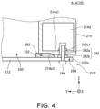
- FIG. 4 is a view showing a lower part of an A-A cross-section in FIG. 3 .
- FIG. 5 is a view showing an upper part of the A-A cross-section in FIG. 3 .
- FIG. 3 does not illustrate the lower plate 212 shown in FIG. 4 and the upper case 220 shown in FIG. 5 .
- FIG. 4 and FIG. 5 do not illustrate a pressure release valve 214h shown in FIG. 3 .
- the battery module 100 (not shown) is disposed.
- FIG. 1 In FIG.
- a circled dot indicating the Z-direction shows that the arrow pointing in the Z-direction extends from the back of the paper surface toward the close side.
- a circled cross indicating the X-direction shows that the arrow pointing in the X-direction extends from the close side of the paper surface toward the back.
- the lower plate 212 includes a first lower mounting part 212a.
- the side frame 214 includes a second lower mounting part 214a1, a first upper mounting part 214a2, a partition wall 214b, and a projecting part 214c.
- the upper case 220 includes a second upper mounting part 220a, an upper cover part 220b, and a side cover part 220c.
- the first lower mounting part 212a and the second lower mounting part 214a1 are opposed to each other via a lower seal material 232.
- the first lower mounting part 212a is at least a portion of an outer peripheral part of the lower plate 212.
- the second lower mounting part 214a1 is at least a portion of a lower part of the side frame 214.
- the lower seal material 232 is, for example, an adhesive. In the embodiment, the lower seal material 232 has fluidity.
- the first lower mounting part 212a and the second lower mounting part 214a1 are fastened to each other by a lower rivet nut 242 and a lower bolt 244.
- the lower rivet nut 242 includes a lower body 242a and a lower head 242b.
- a lower expanding part 242a1 is provided on an outer circumferential surface of the lower body 242a.
- Each of a diameter of the lower expanding part 242a1 in the horizontal direction and a diameter of the lower head 242b in the horizontal direction is larger than a diameter of the lower body 242a in the horizontal direction.
- the lower rivet nut 242 is riveted to the second lower mounting part 214a1 by the lower expanding part 242a1 and the lower head 242b.
- the lower body 242a penetrates substantially parallel to the Z-direction through the second lower mounting part 214a1.
- a tip of the lower body 242a enters a hollow lower space 214d provided inside the side frame 214.
- the side frame 214 can be made lighter compared to the case where the lower space 214d is solid.
- the second lower mounting part 214a1 and the lower rivet nut 242 are fastened to each other, for example, in the following manner.
- the lower body 242a is inserted through the second lower mounting part 214a1. Accordingly, the tip of the lower body 242a enters the lower space 214d.
- a hand nutter (not shown) is inserted through the lower body 242a from below the lower body 242a. Then, the tip of the lower body 242a is pulled downward by the hand nutter. Accordingly, the lower body 242a is deformed to form the lower expanding part 242a1.
- the lower rivet nut 242 is crimped to the second lower mounting part 214a1 by the lower expanding part 242a1 and the lower head 242b.
- the lower bolt 244 penetrates substantially parallel to the Z-direction through the first lower mounting part 212a and is fastened to the lower rivet nut 242. With the lower rivet nut 242 and the lower bolt 244 fastened to each other, the first lower mounting part 212a and the second lower mounting part 214a1 are fastened to each other.
- the second lower mounting part 214a1 and the lower bolt 244 can still be fastened to each other.
- a thickness of the second lower mounting part 214a1 in the Z-direction is relatively small, it may be difficult to form the bolt hole in the second lower mounting part 214a1.
- the second lower mounting part 214a1 and the lower bolt 244 can be fastened to each other via the lower rivet nut 242.
- the second lower mounting part 214a1 and the lower bolt 244 can still be fastened to each other.
- the second lower mounting part 214a1 and the lower bolt 244 can be fastened to each other via the lower rivet nut 242.
- a gap is provided between an upper surface of the first lower mounting part 212a and a lower surface of the second lower mounting part 214a1.
- the gap includes a lower inner space 262 and a lower outer space 264.
- the lower inner space 262 is located on the accommodating space 250 side with respect to the lower outer space 264.
- the lower outer space 264 is located on the outer side of the accommodating space 250 with respect to the lower inner space 262.
- At least a portion of the lower seal material 232 is embedded in at least a portion of the lower inner space 262.
- At least a portion of the lower head 242b is disposed in at least a portion of the lower outer space 264.
- the lower head 242b functions as a spacer that determines a thickness of the lower seal material 232 in the Z-direction. Specifically, a rigidity of the lower head 242b is higher than a rigidity of the lower seal material 232. Thus, a height of the lower inner space 262 in the Z-direction and a height of the lower outer space 264 in the Z-direction can be determined by a height of the lower head 242b in the Z-direction. Therefore, the thickness of the lower seal material 232 in the Z-direction can be accurately adjusted according to the height of the lower head 242b in the Z-direction. As a result, sealing performance of the accommodating space 250 can be improved.
- a distance in the Z-direction between the first lower mounting part 212a and the second lower mounting part 214a1 in the lower outer space 264 is shorter than a distance in the Z-direction between the first lower mounting part 212a and the second lower mounting part 214a1 in the lower inner space 262.
- the distance in the Z-direction between the first lower mounting part 212a and the second lower mounting part 214a1 in the lower outer space 264 may also be equal to or greater than the distance in the Z-direction between the first lower mounting part 212a and the second lower mounting part 214a1 in the lower inner space 262.
- An inclined surface 214a3 is provided on the lower surface of the second lower mounting part 214a1 between the lower inner space 262 and the lower outer space 264.
- the inclined surface 214a3 is inclined downward as it extends toward the outer side of the accommodating space 250.
- the lower seal material 232 when viewed from the Z-direction, is provided over an entire perimeter of the side frame 214. Accordingly, when viewed from the Z-direction, the lower seal material 232 surrounds the accommodating space 250. Thus, the accommodating space 250 can be sealed from the space outside the accommodating body 200 by the lower seal material 232.
- each lower bolt 244 is fastened to the lower rivet nut 242 by the structure described with reference to FIG. 4 .
- the number of the lower bolts 244 provided in the entire perimeter of the side frame 214 may also be one only.
- the fastener fastened to the second lower mounting part 214a1 is not limited to the lower rivet nut 242 according to the embodiment. Examples of such a fastener include not only a rivet nut but also a clinch nut. The fastener may be fastened not only to the second lower mounting part 214a1 but also to the first lower mounting part 212a.
- the fastener that fastens the first lower mounting part 212a and the second lower mounting part 214a1 to each other is not limited to the lower bolt 244 according to the embodiment.
- Examples of such a fastener include not only a bolt but also a screw.
- the first upper mounting part 214a2 and the second upper mounting part 220a are opposed to each other via the upper seal material 234.
- the first upper mounting part 214a2 is at least a portion of an upper part of the side frame 214.
- the second upper mounting part 220a is at least a portion of an outer peripheral part of the upper case 220.
- the upper seal material 234 is an elastic material such as rubber.
- the first upper mounting part 214a2 and the second upper mounting part 220a are fastened to each other by an upper rivet nut 246 and an upper bolt 248.
- the upper rivet nut 246 includes an upper body 246a and an upper head 246b.
- An upper expanding part 246a1 is provided on an outer circumferential surface of the upper body 246a.
- Each of a diameter of the upper expanding part 246a1 in the horizontal direction and a diameter of the upper head 246b in the horizontal direction is larger than a diameter of the upper body 246a in the horizontal direction.
- the upper rivet nut 246 is riveted to the first upper mounting part 214a2 by the upper expanding part 246a1 and the upper head 246b.
- the first upper mounting part 214a2 and the upper rivet nut 246 may be fastened to each other by a method similar to the method of fastening the second lower mounting part 214a1 and the lower rivet nut 242 to each other.
- the upper body 246a penetrates substantially parallel to the Z-direction through the first upper mounting part 214a2.
- a tip of the upper body 246a enters a hollow upper space 214e provided inside the side frame 214.
- the side frame 214 can be made lighter compared to the case where the upper space 214e is solid.
- the upper bolt 248 penetrates substantially parallel to the Z-direction through the second upper mounting part 220a and is fastened to the upper rivet nut 246. With the upper rivet nut 246 and the upper bolt 248 fastened to each other, the first upper mounting part 214a2 and the second upper mounting part 220a are fastened to each other.
- the upper head 246b functions as a spacer that determines a thickness of the upper seal material 234 in the Z-direction. Specifically, a rigidity of the upper head 246b is higher than a rigidity of the upper seal material 234. Thus, a height in the Z-direction of a gap between an upper surface of the first upper mounting part 214a2 and a lower surface of the second upper mounting part 220a can be determined by a height of the upper head 246b. Therefore, the thickness of the upper seal material 234 in the Z-direction can be accurately adjusted according to the height of the upper head 246b in the Z-direction. As a result, sealing performance of the accommodating space 250 can be improved.
- the upper seal material 234 when viewed from the Z-direction, is provided over the entire perimeter of the side frame 214. Accordingly, when viewed from the Z-direction, the upper seal material 234 surrounds the accommodating space 250. Thus, the accommodating space 250 can be sealed from the space outside the accommodating body 200 by the upper seal material 234.
- each upper bolt 248 is disposed at predetermined intervals over the entire perimeter of the side frame 214.
- Each upper bolt 248 is fastened to the upper rivet nut 246 by the structure described with reference to FIG. 5 .
- the number of the upper bolts 248 provided in the entire perimeter of the side frame 214 may also be one only.
- the fastener fastened to the first upper mounting part 214a2 is not limited to the upper rivet nut 246 according to the embodiment. Examples of such a fastener include not only a rivet nut but also a clinch nut. The fastener may be fastened not only to the first upper mounting part 214a2 but also to the second upper mounting part 220a.
- the fastener that fastens the first upper mounting part 214a2 and the second upper mounting part 220a to each other is not limited to the upper bolt 248 according to the embodiment.
- Examples of such a fastener include not only a bolt but also a screw.
- gas may be generated from the battery module 100.
- a gas discharge path 214f is provided inside the side frame 214.
- the gas discharge path 214f is hollow.
- the gas discharge path 214f is located between the lower space 214d and the upper space 214e in the Z-direction.
- multiple gas discharge holes 214g are provided on an inner surface of the side frame 214. When viewed from the Z-direction, the multiple gas discharge holes 214g are disposed at predetermined intervals over the entire perimeter of the side frame 214.
- the accommodating space 250 and the gas discharge path 214f are in communication with each other via the multiple gas discharge holes 214g.
- a pressure release valve 214h is provided on a portion of an outer surface of the side frame 214.
- the upper cover part 220b When viewed from the Z-direction, the upper cover part 220b is surrounded by the second upper mounting part 220a.
- the upper cover part 220b covers the accommodating space 250 from above.
- the partition wall 214b protrudes upward from the first upper mounting part 214a2. As shown in FIG. 5 , the partition wall 214b is provided at an inner end part of the first upper mounting part 214a2. Accordingly, the partition wall 214b is located between the battery module 100 and the upper seal material 234. Thus, the partition wall 214b can separate the battery module 100 and the upper seal material 234 from each other. As shown in FIG. 3 , when viewed from the Z-direction, the partition wall 214b extends continuously in the entire perimeter of the side frame 214. However, the partition wall 214b may also be partially disconnected in the entire perimeter of the side frame 214.
- the partition wall 214b may function as at least a portion of a structure body that blocks direct injection of the high-temperature gas onto the upper seal material 234.
- an upper surface of the partition wall 214b is located at a position higher than an upper surface of the upper seal material 234.
- the upper surface of the partition wall 214b is located at a position higher than an upper surface of the upper head 246b.
- the upper surface of the partition wall 214b may also be located at a position lower than the upper surface of the upper seal material 234.
- the upper surface of the partition wall 214b and the upper surface of the upper seal material 234 may also be substantially flush with each other.
- the side cover part 220c When viewed from the Z-direction, the side cover part 220c is provided at an outer edge of the second upper mounting part 220a. As shown in FIG. 5 , a lower end of the side cover part 220c protrudes downward from the outer edge of the second upper mounting part 220a.
- the side cover part 220c covers a surface of the upper seal material 234 on a side opposite to the accommodating space 250. Under predetermined conditions of washing and the like of the automobile in which the battery pack 10 is mounted, high-pressure water may be sprayed from the outer side of the accommodating body 200.
- the side cover part 220c may function as at least a portion of a structure body that blocks direct injection of the water onto the upper seal material 234.
- the projecting part 214c is located below the side cover part 220c.
- the projecting part 214c projects more outward than the side cover part 220c.
- the projecting part 214c when viewed from the Z-direction, extends continuously in the entire perimeter of the side frame 214. However, the projecting part 214c may also be partially disconnected in the entire perimeter of the side frame 214. Under predetermined conditions of washing and the like of the automobile in which the battery pack 10 is mounted, high-pressure water may be sprayed diagonally from below on the outer side of the accommodating body 200.
- the projecting part 214c may function as at least a portion of a structure body that blocks direct injection of the water onto the upper seal material 234.
- the fastening structure between the first lower mounting part 212a of the lower case 210 and the second lower mounting part 214a1 of the side frame 214, and the fastening structure between the first upper mounting part 214a2 of the side frame 214 and the second upper mounting part 220a of the upper case 220 have been described.
- These fastening structures may also be applied to two other mounting parts opposed to each other via a seal material.
Landscapes
- Chemical & Material Sciences (AREA)
- Chemical Kinetics & Catalysis (AREA)
- Electrochemistry (AREA)
- General Chemical & Material Sciences (AREA)
- Battery Mounting, Suspending (AREA)
Abstract
A battery pack (10) comprises: a housing (200) which includes a first lower mount portion (212a) and a second lower mount portion (214a1) that oppose each other with a lower seal material (232) therebetween; a battery module (100) housed in the housing (200); a lower rivet nut (242) which is fastened to at least one of the first lower mount portion (212a) and the second lower mount portion (214a1), and at least a part of which is positioned between the first lower mount portion (212a) and the second lower mount portion (214a1); and a lower bolt (244) that is fastened to the lower rivet nut (242) and fastens the first lower mount portion (212a) and the second lower mount portion (214a1) to each other.
Description
- The present invention relates to a battery pack.
- In recent years, battery packs have been developed to be used for various applications such as automobiles. A battery pack includes at least one battery module and an accommodating body in which the at least one module is accommodated.
- Patent Literature 1 describes an example of a battery pack. In this battery pack, the accommodating body includes a tray member and a lid member. The tray member and the lid member are fastened to each other by a fastening member via a gasket member.
- Patent Literature 1:
Japanese Patent Application Laid-Open No. 2014-175123 - The accommodating body may include two mounting parts opposed to each other via a seal material. These two fastening parts may be fastened to each other by a fastener. In this case, improvement in sealing performance of an accommodating space of the accommodating body may be required. To improve sealing performance of the accommodating space, it is preferable to accurately adjust a thickness of the seal material. However, if the seal material is simply disposed, it may be difficult to accurately adjust the thickness of the seal material.
- An example of an objective of the present invention is to improve sealing performance of the accommodating space of the accommodating body. Other objectives of the present invention will become apparent from the description in this specification.
- An aspect of the present invention is as follows.
- [1] A battery pack includes an accommodating body, a battery module, a first fastener, and a second fastener. The accommodating body includes two mounting parts opposed to each other via a seal material. The battery module is accommodated in the accommodating body. The first fastener is fastened to at least one of the two mounting parts, and at least a portion of the first fastener is located between the two mounting parts. The second fastener is fastened to the first fastener and fastens the two mounting parts to each other.
- [2] In the battery pack according to [1], a portion of the first fastener enters a space provided inside the accommodating body.
- [3] In the battery pack according to [1] or [2], a gap between the two mounting parts includes a first space in which at least a portion of the seal material is embedded, and a second space in which the at least a portion of the first fastener is disposed. A distance between the two mounting parts on both sides of the second space is shorter than a distance between the two mounting parts on both sides of the first space.
- [4] In the battery pack according to [3], an inclined surface is provided on at least a portion of the two mounting parts between the first space and the second space.
- According to the above aspect of the present invention, sealing performance of the accommodating space of the accommodating body can be improved.
-
- [
FIG. 1 ] is a perspective view of a battery pack according to an embodiment. - [
FIG. 2 ] is a plan view of the battery pack according to the embodiment with an upper case removed. - [
FIG. 3 ] is an enlarged plan view of a portion of a side frame according to the embodiment. - [
FIG. 4 ] is a view showing a lower part of an A-A cross-section ofFIG. 3 . - [
FIG. 5 ] is a view showing an upper part of the A-A cross-section ofFIG. 3 . - Hereinafter, an embodiment of the present invention will be described with reference to the drawings. In all drawings, similar constituent elements will be labeled with similar reference signs, and descriptions thereof will be omitted as appropriate.
-
FIG. 1 is a perspective view of abattery pack 10 according to the embodiment.FIG. 2 is a plan view of thebattery pack 10 according to the embodiment with anupper case 220 removed. - In the embodiment, the
battery pack 10 is mounted in an automobile. Specifically, thebattery pack 10 is mounted between front wheels and rear wheels of the automobile. Hereinafter, unless otherwise specified, the description will be provided assuming that thebattery pack 10 is mounted in an automobile. However, thebattery pack 10 may also be applied to uses other than an automobile. - In each figure, an X-direction, a Y-direction, and a Z-direction are shown to facilitate description. The X-direction indicates a front-rear direction of the
battery pack 10. The Y-direction is orthogonal to the X-direction. The Y-direction indicates a left-right direction of thebattery pack 10. The Z-direction is orthogonal to both the X-direction and the Y-direction. The Z-direction indicates an up-down direction of thebattery pack 10. Arrows pointing in the X-direction, the Y-direction, and the Z-direction respectively indicate a front direction, a left direction, and an upper direction of thebattery pack 10. InFIG. 2 , a circled dot indicating the Z-direction shows that the arrow pointing in the Z-direction extends from the back of the paper surface toward the close side. However, the relationship between the X-direction, the Y-direction, and the Z-direction, and the front-rear direction, the left-right direction, and the up-down direction of thebattery pack 10 is not limited to this example. - In the embodiment, the front-rear direction, the left-right direction, and the up-down direction of the
battery pack 10 are determined by the automobile in which thebattery pack 10 is mounted. The X-direction, the Y-direction, and the Z-direction respectively indicate a front-rear direction, a left-right direction, and an up-down direction of the automobile. The arrows pointing in the X-direction, the Y-direction, and the Z-direction respectively indicate a front direction, a left direction, and an upper direction of the automobile. However, the relationship between the front-rear direction, the left-right direction, and the up-down direction of thebattery pack 10, and the front-rear direction, the left-right direction, and the up-down direction of the automobile is not limited to this example. - Hereinafter, wherever necessary, a direction perpendicular to the Z-direction will be referred to as a horizontal direction.
- The
battery pack 10 includes fourbattery modules 100 and anaccommodating body 200. The fourbattery modules 100 include a pair ofbattery modules 100 arranged in the X-direction on a left side and a pair ofbattery modules 100 arranged in the X-direction on a right side. Theaccommodating body 200 has alower case 210 and anupper case 220. Thelower case 210 may also be generally referred to as, for example, a tray or a main body. Thelower case 210 includes alower plate 212 and aside frame 214. Theupper case 220 may also be generally referred to as, for example, a cover or a lid part. - Each
battery module 100 has multiple battery cells stacked in the horizontal direction. For example, in eachbattery module 100, multiple battery cell groups are connected in series, with each battery cell group including multiple battery cells connected in parallel. Alternatively, multiple single battery cells may also be connected in series. - A pair of
terminals 110 is provided on a front side of theside frame 214. The pair ofterminals 110 is arranged substantially parallel to the Y-direction. A front end part of each terminal 110 protrudes forward from a front surface of theside frame 214. In an electrical path, the fourbattery modules 100 are connected in series between the pair ofterminals 110. - The
lower case 210 and theupper case 220 are mounted to each other via anupper seal material 234. Thelower case 210, theupper case 220, and theupper seal material 234 form anaccommodating space 250. The fourbattery modules 100 are accommodated in theaccommodating space 250. - The
lower plate 212 defines a bottom part of theaccommodating space 250. Theside frame 214 defines a lateral part of theaccommodating space 250. Specifically, when viewed from the Z-direction, theside frame 214 is provided along an outermost periphery of thelower plate 212. Theupper case 220 defines a top part of theaccommodating space 250. - The number and arrangement of the battery modules are not limited to the example according to the embodiment. For example, the number of the
battery modules 100 may also be two only, three only, or five or more. -
FIG. 3 is an enlarged plan view of a portion of theside frame 214 according to the embodiment.FIG. 4 is a view showing a lower part of an A-A cross-section inFIG. 3 .FIG. 5 is a view showing an upper part of the A-A cross-section inFIG. 3 . For simplicity of description,FIG. 3 does not illustrate thelower plate 212 shown inFIG. 4 and theupper case 220 shown inFIG. 5 . For simplicity of description,FIG. 4 andFIG. 5 do not illustrate apressure release valve 214h shown inFIG. 3 . In theaccommodating space 250 in the cross-sections shown inFIG. 4 andFIG. 5 , the battery module 100 (not shown) is disposed. InFIG. 3 , a circled dot indicating the Z-direction shows that the arrow pointing in the Z-direction extends from the back of the paper surface toward the close side. InFIG. 4 andFIG. 5 , a circled cross indicating the X-direction shows that the arrow pointing in the X-direction extends from the close side of the paper surface toward the back. - As shown in
FIG. 4 , thelower plate 212 includes a first lower mountingpart 212a. As shown inFIG. 4 andFIG. 5 , theside frame 214 includes a second lower mounting part 214a1, a first upper mounting part 214a2, apartition wall 214b, and a projectingpart 214c. As shown inFIG. 5 , theupper case 220 includes a secondupper mounting part 220a, anupper cover part 220b, and aside cover part 220c. - Referring to
FIG. 4 , a fastening structure of thelower plate 212 and theside frame 214 will be described. - As shown in
FIG. 4 , the first lower mountingpart 212a and the second lower mounting part 214a1 are opposed to each other via alower seal material 232. The first lower mountingpart 212a is at least a portion of an outer peripheral part of thelower plate 212. The second lower mounting part 214a1 is at least a portion of a lower part of theside frame 214. Thelower seal material 232 is, for example, an adhesive. In the embodiment, thelower seal material 232 has fluidity. - The first lower mounting
part 212a and the second lower mounting part 214a1 are fastened to each other by alower rivet nut 242 and alower bolt 244. Thelower rivet nut 242 includes alower body 242a and alower head 242b. A lower expanding part 242a1 is provided on an outer circumferential surface of thelower body 242a. Each of a diameter of the lower expanding part 242a1 in the horizontal direction and a diameter of thelower head 242b in the horizontal direction is larger than a diameter of thelower body 242a in the horizontal direction. Thelower rivet nut 242 is riveted to the second lower mounting part 214a1 by the lower expanding part 242a1 and thelower head 242b. - The
lower body 242a penetrates substantially parallel to the Z-direction through the second lower mounting part 214a1. A tip of thelower body 242a enters a hollowlower space 214d provided inside theside frame 214. In the case where thelower space 214d is provided, theside frame 214 can be made lighter compared to the case where thelower space 214d is solid. - The second lower mounting part 214a1 and the
lower rivet nut 242 are fastened to each other, for example, in the following manner. First, thelower body 242a is inserted through the second lower mounting part 214a1. Accordingly, the tip of thelower body 242a enters thelower space 214d. Next, a hand nutter (not shown) is inserted through thelower body 242a from below thelower body 242a. Then, the tip of thelower body 242a is pulled downward by the hand nutter. Accordingly, thelower body 242a is deformed to form the lower expanding part 242a1. Thus, thelower rivet nut 242 is crimped to the second lower mounting part 214a1 by the lower expanding part 242a1 and thelower head 242b. - The
lower bolt 244 penetrates substantially parallel to the Z-direction through the first lower mountingpart 212a and is fastened to thelower rivet nut 242. With thelower rivet nut 242 and thelower bolt 244 fastened to each other, the first lower mountingpart 212a and the second lower mounting part 214a1 are fastened to each other. - In the embodiment, even in the case where it is difficult to form a bolt hole in the second lower mounting part 214a1 to fasten the
lower bolt 244, the second lower mounting part 214a1 and thelower bolt 244 can still be fastened to each other. For example, in the case where a thickness of the second lower mounting part 214a1 in the Z-direction is relatively small, it may be difficult to form the bolt hole in the second lower mounting part 214a1. In contrast, in the embodiment, the second lower mounting part 214a1 and thelower bolt 244 can be fastened to each other via thelower rivet nut 242. Thus, in the embodiment, it is not required to form the bolt hole in the second lower mounting part 214a1. - In the embodiment, even in the case where it is difficult to provide a nut inside the
lower space 214d to fasten thelower bolt 244, the second lower mounting part 214a1 and thelower bolt 244 can still be fastened to each other. For example, in the case where thelower space 214d is closed off from the space outside theside frame 214, it may be difficult to provide the nut inside thelower space 214d. In contrast, in the embodiment, the second lower mounting part 214a1 and thelower bolt 244 can be fastened to each other via thelower rivet nut 242. Thus, in the embodiment, it is not required to provide the nut inside thelower space 214d. - A gap is provided between an upper surface of the first lower mounting
part 212a and a lower surface of the second lower mounting part 214a1. The gap includes a lowerinner space 262 and a lowerouter space 264. The lowerinner space 262 is located on theaccommodating space 250 side with respect to the lowerouter space 264. The lowerouter space 264 is located on the outer side of theaccommodating space 250 with respect to the lowerinner space 262. At least a portion of thelower seal material 232 is embedded in at least a portion of the lowerinner space 262. At least a portion of thelower head 242b is disposed in at least a portion of the lowerouter space 264. - The
lower head 242b functions as a spacer that determines a thickness of thelower seal material 232 in the Z-direction. Specifically, a rigidity of thelower head 242b is higher than a rigidity of thelower seal material 232. Thus, a height of the lowerinner space 262 in the Z-direction and a height of the lowerouter space 264 in the Z-direction can be determined by a height of thelower head 242b in the Z-direction. Therefore, the thickness of thelower seal material 232 in the Z-direction can be accurately adjusted according to the height of thelower head 242b in the Z-direction. As a result, sealing performance of theaccommodating space 250 can be improved. - In the example shown in
FIG. 4 , a right end part of thelower seal material 232 enters a left end part of the lowerouter space 264. In the embodiment, an amount of a portion of thelower seal material 232 that enters the lowerouter space 264 can be adjusted according to the height of thelower head 242b in the Z-direction. Accordingly, it is possible to make it less likely for the portion of thelower seal material 232 entering the lowerouter space 264 to run onto thelower head 242b. - A distance in the Z-direction between the first lower mounting
part 212a and the second lower mounting part 214a1 in the lowerouter space 264 is shorter than a distance in the Z-direction between the first lower mountingpart 212a and the second lower mounting part 214a1 in the lowerinner space 262. Thus, compared to the case where these distances are equal to each other, it is possible to make it less likely for thelower seal material 232 to enter the lowerouter space 264. As a result, it is possible to make it less likely for thelower seal material 232 to run onto thelower head 242b. However, the distance in the Z-direction between the first lower mountingpart 212a and the second lower mounting part 214a1 in the lowerouter space 264 may also be equal to or greater than the distance in the Z-direction between the first lower mountingpart 212a and the second lower mounting part 214a1 in the lowerinner space 262. - An inclined surface 214a3 is provided on the lower surface of the second lower mounting part 214a1 between the lower
inner space 262 and the lowerouter space 264. The inclined surface 214a3 is inclined downward as it extends toward the outer side of theaccommodating space 250. By adjusting an inclination of the inclined surface 214a3 with respect to the horizontal direction, the amount of the portion of thelower seal material 232 entering the lowerouter space 264 can be adjusted. - In the embodiment, when viewed from the Z-direction, the
lower seal material 232 is provided over an entire perimeter of theside frame 214. Accordingly, when viewed from the Z-direction, thelower seal material 232 surrounds theaccommodating space 250. Thus, theaccommodating space 250 can be sealed from the space outside theaccommodating body 200 by thelower seal material 232. - In the embodiment, when viewed from the Z-direction, multiple
lower bolts 244 are disposed at predetermined intervals over the entire perimeter of theside frame 214. Eachlower bolt 244 is fastened to thelower rivet nut 242 by the structure described with reference toFIG. 4 . The number of thelower bolts 244 provided in the entire perimeter of theside frame 214 may also be one only. - The fastener fastened to the second lower mounting part 214a1 is not limited to the
lower rivet nut 242 according to the embodiment. Examples of such a fastener include not only a rivet nut but also a clinch nut. The fastener may be fastened not only to the second lower mounting part 214a1 but also to the first lower mountingpart 212a. - The fastener that fastens the first lower mounting
part 212a and the second lower mounting part 214a1 to each other is not limited to thelower bolt 244 according to the embodiment. Examples of such a fastener include not only a bolt but also a screw. - Referring to
FIG. 5 , and toFIG. 3 wherever necessary, a fastening structure of theside frame 214 and theupper case 220 will be described. - As shown in
FIG. 5 , the first upper mounting part 214a2 and the secondupper mounting part 220a are opposed to each other via theupper seal material 234. The first upper mounting part 214a2 is at least a portion of an upper part of theside frame 214. The secondupper mounting part 220a is at least a portion of an outer peripheral part of theupper case 220. Theupper seal material 234 is an elastic material such as rubber. - The first upper mounting part 214a2 and the second
upper mounting part 220a are fastened to each other by anupper rivet nut 246 and anupper bolt 248. Theupper rivet nut 246 includes anupper body 246a and anupper head 246b. An upper expanding part 246a1 is provided on an outer circumferential surface of theupper body 246a. Each of a diameter of the upper expanding part 246a1 in the horizontal direction and a diameter of theupper head 246b in the horizontal direction is larger than a diameter of theupper body 246a in the horizontal direction. Theupper rivet nut 246 is riveted to the first upper mounting part 214a2 by the upper expanding part 246a1 and theupper head 246b. The first upper mounting part 214a2 and theupper rivet nut 246 may be fastened to each other by a method similar to the method of fastening the second lower mounting part 214a1 and thelower rivet nut 242 to each other. - The
upper body 246a penetrates substantially parallel to the Z-direction through the first upper mounting part 214a2. A tip of theupper body 246a enters a hollowupper space 214e provided inside theside frame 214. In the case where theupper space 214e is provided, theside frame 214 can be made lighter compared to the case where theupper space 214e is solid. - The
upper bolt 248 penetrates substantially parallel to the Z-direction through the secondupper mounting part 220a and is fastened to theupper rivet nut 246. With theupper rivet nut 246 and theupper bolt 248 fastened to each other, the first upper mounting part 214a2 and the secondupper mounting part 220a are fastened to each other. - In the embodiment, as described in the description of the fastening structure of the
lower plate 212 and theside frame 214, it is not required to form a bolt hole in the first upper mounting part 214a2 to fasten theupper bolt 248. Similarly, it is not required to provide a nut inside theupper space 214e to fasten theupper bolt 248. - The
upper head 246b functions as a spacer that determines a thickness of theupper seal material 234 in the Z-direction. Specifically, a rigidity of theupper head 246b is higher than a rigidity of theupper seal material 234. Thus, a height in the Z-direction of a gap between an upper surface of the first upper mounting part 214a2 and a lower surface of the secondupper mounting part 220a can be determined by a height of theupper head 246b. Therefore, the thickness of theupper seal material 234 in the Z-direction can be accurately adjusted according to the height of theupper head 246b in the Z-direction. As a result, sealing performance of theaccommodating space 250 can be improved. - In the embodiment, when viewed from the Z-direction, the
upper seal material 234 is provided over the entire perimeter of theside frame 214. Accordingly, when viewed from the Z-direction, theupper seal material 234 surrounds theaccommodating space 250. Thus, theaccommodating space 250 can be sealed from the space outside theaccommodating body 200 by theupper seal material 234. - As shown in
FIG. 3 , in the embodiment, when viewed from the Z-direction, multipleupper bolts 248 are disposed at predetermined intervals over the entire perimeter of theside frame 214. Eachupper bolt 248 is fastened to theupper rivet nut 246 by the structure described with reference toFIG. 5 . The number of theupper bolts 248 provided in the entire perimeter of theside frame 214 may also be one only. - The fastener fastened to the first upper mounting part 214a2 is not limited to the
upper rivet nut 246 according to the embodiment. Examples of such a fastener include not only a rivet nut but also a clinch nut. The fastener may be fastened not only to the first upper mounting part 214a2 but also to the secondupper mounting part 220a. - The fastener that fastens the first upper mounting part 214a2 and the second
upper mounting part 220a to each other is not limited to theupper bolt 248 according to the embodiment. Examples of such a fastener include not only a bolt but also a screw. - Referring to
FIG. 3 andFIG. 5 , a structure for discharging gas from theaccommodating space 250 will be described. Inside theaccommodating space 250, gas may be generated from thebattery module 100. - As shown in
FIG. 5 , agas discharge path 214f is provided inside theside frame 214. Thegas discharge path 214f is hollow. Thegas discharge path 214f is located between thelower space 214d and theupper space 214e in the Z-direction. As shown inFIG. 3 , multiple gas discharge holes 214g are provided on an inner surface of theside frame 214. When viewed from the Z-direction, the multiple gas discharge holes 214g are disposed at predetermined intervals over the entire perimeter of theside frame 214. Theaccommodating space 250 and thegas discharge path 214f are in communication with each other via the multiple gas discharge holes 214g. As shown inFIG. 3 , apressure release valve 214h is provided on a portion of an outer surface of theside frame 214. Thus, gas generated from thebattery module 100 inside theaccommodating space 250 can be discharged to outside of theaccommodating body 200 through the gas discharge holes 214g and thegas discharge path 214f from thepressure release valve 214h. - Referring to
FIG. 3 andFIG. 5 , the structure on the inner side in the Y-direction of theaccommodating body 200 with respect to theupper seal material 234 will be described. - When viewed from the Z-direction, the
upper cover part 220b is surrounded by the secondupper mounting part 220a. Theupper cover part 220b covers theaccommodating space 250 from above. - The
partition wall 214b protrudes upward from the first upper mounting part 214a2. As shown inFIG. 5 , thepartition wall 214b is provided at an inner end part of the first upper mounting part 214a2. Accordingly, thepartition wall 214b is located between thebattery module 100 and theupper seal material 234. Thus, thepartition wall 214b can separate thebattery module 100 and theupper seal material 234 from each other. As shown inFIG. 3 , when viewed from the Z-direction, thepartition wall 214b extends continuously in the entire perimeter of theside frame 214. However, thepartition wall 214b may also be partially disconnected in the entire perimeter of theside frame 214. Under predetermined conditions of charging and discharging and the like of thebattery module 100, high-temperature gas may be generated from thebattery module 100. Thepartition wall 214b may function as at least a portion of a structure body that blocks direct injection of the high-temperature gas onto theupper seal material 234. - In the example shown in
FIG. 5 , an upper surface of thepartition wall 214b is located at a position higher than an upper surface of theupper seal material 234. In other words, the upper surface of thepartition wall 214b is located at a position higher than an upper surface of theupper head 246b. Thus, compared to the case where the upper surface of thepartition wall 214b is located at a position lower than the upper surface of theupper seal material 234, it is possible to make it less likely for the high-temperature gas described above to be directly injected onto theupper seal material 234. However, the upper surface of thepartition wall 214b may also be located at a position lower than the upper surface of theupper seal material 234. Alternatively, the upper surface of thepartition wall 214b and the upper surface of theupper seal material 234 may also be substantially flush with each other. - Referring to
FIG. 3 andFIG. 5 , the structure on the outer side of theaccommodating body 200 in the Y-direction with respect to theupper seal material 234 will be described. - When viewed from the Z-direction, the
side cover part 220c is provided at an outer edge of the secondupper mounting part 220a. As shown inFIG. 5 , a lower end of theside cover part 220c protrudes downward from the outer edge of the secondupper mounting part 220a. The side coverpart 220c covers a surface of theupper seal material 234 on a side opposite to theaccommodating space 250. Under predetermined conditions of washing and the like of the automobile in which thebattery pack 10 is mounted, high-pressure water may be sprayed from the outer side of theaccommodating body 200. The side coverpart 220c may function as at least a portion of a structure body that blocks direct injection of the water onto theupper seal material 234. - As shown in
FIG. 5 , the projectingpart 214c is located below theside cover part 220c. The projectingpart 214c projects more outward than theside cover part 220c. As shown inFIG. 3 , when viewed from the Z-direction, the projectingpart 214c extends continuously in the entire perimeter of theside frame 214. However, the projectingpart 214c may also be partially disconnected in the entire perimeter of theside frame 214. Under predetermined conditions of washing and the like of the automobile in which thebattery pack 10 is mounted, high-pressure water may be sprayed diagonally from below on the outer side of theaccommodating body 200. The projectingpart 214c may function as at least a portion of a structure body that blocks direct injection of the water onto theupper seal material 234. - The embodiment of the present invention has been described above with reference to the drawings, but these descriptions are examples of the present invention, and various other configurations may also be adopted in addition to those described above.
- For example, in the embodiment, the fastening structure between the first lower mounting
part 212a of thelower case 210 and the second lower mounting part 214a1 of theside frame 214, and the fastening structure between the first upper mounting part 214a2 of theside frame 214 and the secondupper mounting part 220a of theupper case 220 have been described. These fastening structures may also be applied to two other mounting parts opposed to each other via a seal material. - This application claims priority based on
Japanese Patent Application No. 2022- 124576 -
- 10: battery pack
- 100: battery module
- 110: terminal
- 200: accommodating body
- 210: lower case
- 212: lower plate
- 212a: first lower mounting part
- 214: side frame
- 214a1: second lower mounting part
- 214a2: first upper mounting part
- 214a3: inclined surface
- 214b: partition wall
- 214c: projecting part
- 214d: lower space
- 214e: upper space
- 214f: gas discharge path
- 214g: gas discharge hole
- 214h: pressure release valve
- 220: upper case
- 220a: second upper mounting part
- 220b: upper cover part
- 220c: side cover part
- 232: lower seal material
- 234: upper seal material
- 242: lower rivet nut
- 242a: lower body
- 242a1: lower expanding part
- 242b: lower head
- 244: lower bolt
- 246: upper rivet nut
- 246a: upper body
- 246a1: upper expanding part
- 246b: upper head
- 248: upper bolt
- 250: accommodating space
- 262: lower inner space
- 264: lower outer space
Claims (4)
- A battery pack comprising:an accommodating body comprising two mounting parts opposed to each other via a seal material;a battery module accommodated in the accommodating body;a first fastener fastened to at least one of the two mounting parts, at least a portion of the first fastener being located between the two mounting parts; anda second fastener fastened to the first fastener and fastening the two mounting parts to each other.
- The battery pack according to claim 1, wherein a portion of the first fastener enters a space provided inside the accommodating body.
- The battery pack according to claim 1 or 2, wherein a gap between the two mounting parts comprises a first space in which at least a portion of the seal material is embedded, and a second space in which the at least a portion of the first fastener is disposed, and
a distance between the two mounting parts on both sides of the second space is shorter than a distance between the two mounting parts on both sides of the first space. - The battery pack according to claim 3, wherein an inclined surface is provided on at least a portion of the two mounting parts between the first space and the second space.
Applications Claiming Priority (2)
| Application Number | Priority Date | Filing Date | Title |
|---|---|---|---|
| JP2022124576A JP2024021615A (en) | 2022-08-04 | 2022-08-04 | battery pack |
| PCT/JP2023/028265 WO2024029562A1 (en) | 2022-08-04 | 2023-08-02 | Battery pack |
Publications (2)
| Publication Number | Publication Date |
|---|---|
| EP4567981A1 true EP4567981A1 (en) | 2025-06-11 |
| EP4567981A4 EP4567981A4 (en) | 2025-06-11 |
Family
ID=89849428
Family Applications (1)
| Application Number | Title | Priority Date | Filing Date |
|---|---|---|---|
| EP23850116.7A Pending EP4567981A4 (en) | 2022-08-04 | 2023-08-02 | BATTERY PACK |
Country Status (4)
| Country | Link |
|---|---|
| EP (1) | EP4567981A4 (en) |
| JP (1) | JP2024021615A (en) |
| CN (1) | CN119585926A (en) |
| WO (1) | WO2024029562A1 (en) |
Cited By (1)
| Publication number | Priority date | Publication date | Assignee | Title |
|---|---|---|---|---|
| EP4571966A4 (en) * | 2022-08-10 | 2025-10-01 | Aesc Japan Ltd | BATTERY PACK |
Family Cites Families (11)
| Publication number | Priority date | Publication date | Assignee | Title |
|---|---|---|---|---|
| JP5958545B2 (en) * | 2012-09-14 | 2016-08-02 | 日産自動車株式会社 | Pressure release structure for in-vehicle battery pack |
| JP6094740B2 (en) | 2013-03-07 | 2017-03-15 | 三菱自動車工業株式会社 | Electrical case |
| JP6613787B2 (en) * | 2015-10-14 | 2019-12-04 | 株式会社豊田自動織機 | Battery pack and battery pack assembling method |
| JP2017220344A (en) * | 2016-06-07 | 2017-12-14 | 株式会社豊田自動織機 | Battery pack |
| JP2018041716A (en) * | 2016-09-01 | 2018-03-15 | 株式会社豊田自動織機 | Battery pack |
| JP7020804B2 (en) * | 2017-06-19 | 2022-02-16 | 本田技研工業株式会社 | Battery pack |
| CN207165693U (en) * | 2017-09-15 | 2018-03-30 | 江苏维科新能源科技有限公司 | A kind of sealing structure of lithium battery group |
| CN209641710U (en) * | 2019-04-19 | 2019-11-15 | 东风汽车有限公司 | battery pack shell |
| DE102019210790B4 (en) * | 2019-07-22 | 2023-11-02 | Volkswagen Aktiengesellschaft | Battery housing for a vehicle battery |
| KR102464315B1 (en) * | 2020-12-18 | 2022-11-09 | 주식회사 성우하이텍 | Assembly structure of battery case for electric vehicle |
| JP2022124576A (en) | 2021-02-16 | 2022-08-26 | 住友重機械工業株式会社 | Fluid actuator, control method, and control program |
-
2022
- 2022-08-04 JP JP2022124576A patent/JP2024021615A/en active Pending
-
2023
- 2023-08-02 WO PCT/JP2023/028265 patent/WO2024029562A1/en not_active Ceased
- 2023-08-02 EP EP23850116.7A patent/EP4567981A4/en active Pending
- 2023-08-02 CN CN202380055980.2A patent/CN119585926A/en active Pending
Cited By (1)
| Publication number | Priority date | Publication date | Assignee | Title |
|---|---|---|---|---|
| EP4571966A4 (en) * | 2022-08-10 | 2025-10-01 | Aesc Japan Ltd | BATTERY PACK |
Also Published As
| Publication number | Publication date |
|---|---|
| WO2024029562A1 (en) | 2024-02-08 |
| EP4567981A4 (en) | 2025-06-11 |
| CN119585926A (en) | 2025-03-07 |
| JP2024021615A (en) | 2024-02-16 |
Similar Documents
| Publication | Publication Date | Title |
|---|---|---|
| EP3345779B1 (en) | Vehicle body part and vehicle with integrated battery system | |
| CN112151709B (en) | Battery pack and vehicle | |
| US10759262B2 (en) | Battery pack | |
| CN108001181B (en) | Traction battery retention assembly | |
| EP2767428B1 (en) | Structure for mounting electric power storage device | |
| CN110088939A (en) | Battery pack with scalable battery module structure | |
| US20210229541A1 (en) | Battery assembly having a cross-member and method of managing loads utilizing a cross-member | |
| EP4618276A1 (en) | Lower case body of battery, battery, and electrical apparatus | |
| US20250329852A1 (en) | Battery Pack | |
| WO2025112318A1 (en) | Underbody, vehicle body structure, and vehicle | |
| US20240075799A1 (en) | Traction battery pack support system and method of securing a battery pack to an electrified vehicle | |
| CN116235356B (en) | Box, battery and electrical device | |
| CN119585926A (en) | Battery Pack | |
| JP7674048B2 (en) | Battery pack and automobile including same | |
| KR20190061390A (en) | Battery pack with asymmetric arrangement | |
| US20240322341A1 (en) | Battery module assembly | |
| US20250010699A1 (en) | Inverted battery pack assembly | |
| US20230307805A1 (en) | Standoff assemblies for traction battery packs with cell-to-pack battery systems | |
| US12424695B2 (en) | Retention assemblies for traction battery packs with cell-to-pack battery systems | |
| CN118578902A (en) | System and method for sealing interface of traction battery pack | |
| KR20240138823A (en) | Battery pack | |
| US20260081290A1 (en) | Battery pack | |
| US20260066427A1 (en) | Battery pack | |
| US12388131B2 (en) | Ventilation system for a vehicle battery | |
| EP4583292A1 (en) | Battery pack |
Legal Events
| Date | Code | Title | Description |
|---|---|---|---|
| STAA | Information on the status of an ep patent application or granted ep patent |
Free format text: STATUS: THE INTERNATIONAL PUBLICATION HAS BEEN MADE |
|
| PUAI | Public reference made under article 153(3) epc to a published international application that has entered the european phase |
Free format text: ORIGINAL CODE: 0009012 |
|
| STAA | Information on the status of an ep patent application or granted ep patent |
Free format text: STATUS: REQUEST FOR EXAMINATION WAS MADE |
|
| 17P | Request for examination filed |
Effective date: 20250127 |
|
| A4 | Supplementary search report drawn up and despatched |
Effective date: 20250320 |
|
| AK | Designated contracting states |
Kind code of ref document: A1 Designated state(s): AL AT BE BG CH CY CZ DE DK EE ES FI FR GB GR HR HU IE IS IT LI LT LU LV MC ME MK MT NL NO PL PT RO RS SE SI SK SM TR |
|
| DAV | Request for validation of the european patent (deleted) | ||
| DAX | Request for extension of the european patent (deleted) |