EP4567943A1 - Bilayer membranes composed of two interconnected layers with different phosphoric acid doping ability - Google Patents
Bilayer membranes composed of two interconnected layers with different phosphoric acid doping ability Download PDFInfo
- Publication number
- EP4567943A1 EP4567943A1 EP23215092.0A EP23215092A EP4567943A1 EP 4567943 A1 EP4567943 A1 EP 4567943A1 EP 23215092 A EP23215092 A EP 23215092A EP 4567943 A1 EP4567943 A1 EP 4567943A1
- Authority
- EP
- European Patent Office
- Prior art keywords
- copolymer
- membrane
- formula
- layer
- bilayer
- Prior art date
- Legal status (The legal status is an assumption and is not a legal conclusion. Google has not performed a legal analysis and makes no representation as to the accuracy of the status listed.)
- Pending
Links
Images



Classifications
-
- H—ELECTRICITY
- H01—ELECTRIC ELEMENTS
- H01M—PROCESSES OR MEANS, e.g. BATTERIES, FOR THE DIRECT CONVERSION OF CHEMICAL ENERGY INTO ELECTRICAL ENERGY
- H01M8/00—Fuel cells; Manufacture thereof
- H01M8/10—Fuel cells with solid electrolytes
- H01M8/1016—Fuel cells with solid electrolytes characterised by the electrolyte material
- H01M8/1018—Polymeric electrolyte materials
- H01M8/102—Polymeric electrolyte materials characterised by the chemical structure of the main chain of the ion-conducting polymer
- H01M8/1027—Polymeric electrolyte materials characterised by the chemical structure of the main chain of the ion-conducting polymer having carbon, oxygen and other atoms, e.g. sulfonated polyethersulfones [S-PES]
-
- C—CHEMISTRY; METALLURGY
- C25—ELECTROLYTIC OR ELECTROPHORETIC PROCESSES; APPARATUS THEREFOR
- C25B—ELECTROLYTIC OR ELECTROPHORETIC PROCESSES FOR THE PRODUCTION OF COMPOUNDS OR NON-METALS; APPARATUS THEREFOR
- C25B13/00—Diaphragms; Spacing elements
- C25B13/04—Diaphragms; Spacing elements characterised by the material
- C25B13/08—Diaphragms; Spacing elements characterised by the material based on organic materials
-
- H—ELECTRICITY
- H01—ELECTRIC ELEMENTS
- H01M—PROCESSES OR MEANS, e.g. BATTERIES, FOR THE DIRECT CONVERSION OF CHEMICAL ENERGY INTO ELECTRICAL ENERGY
- H01M8/00—Fuel cells; Manufacture thereof
- H01M8/10—Fuel cells with solid electrolytes
- H01M8/1016—Fuel cells with solid electrolytes characterised by the electrolyte material
- H01M8/1018—Polymeric electrolyte materials
- H01M8/102—Polymeric electrolyte materials characterised by the chemical structure of the main chain of the ion-conducting polymer
- H01M8/103—Polymeric electrolyte materials characterised by the chemical structure of the main chain of the ion-conducting polymer having nitrogen, e.g. sulfonated polybenzimidazoles [S-PBI], polybenzimidazoles with phosphoric acid, sulfonated polyamides [S-PA] or sulfonated polyphosphazenes [S-PPh]
-
- H—ELECTRICITY
- H01—ELECTRIC ELEMENTS
- H01M—PROCESSES OR MEANS, e.g. BATTERIES, FOR THE DIRECT CONVERSION OF CHEMICAL ENERGY INTO ELECTRICAL ENERGY
- H01M8/00—Fuel cells; Manufacture thereof
- H01M8/10—Fuel cells with solid electrolytes
- H01M8/1016—Fuel cells with solid electrolytes characterised by the electrolyte material
- H01M8/1018—Polymeric electrolyte materials
- H01M8/102—Polymeric electrolyte materials characterised by the chemical structure of the main chain of the ion-conducting polymer
- H01M8/1032—Polymeric electrolyte materials characterised by the chemical structure of the main chain of the ion-conducting polymer having sulfur, e.g. sulfonated-polyethersulfones [S-PES]
-
- H—ELECTRICITY
- H01—ELECTRIC ELEMENTS
- H01M—PROCESSES OR MEANS, e.g. BATTERIES, FOR THE DIRECT CONVERSION OF CHEMICAL ENERGY INTO ELECTRICAL ENERGY
- H01M8/00—Fuel cells; Manufacture thereof
- H01M8/10—Fuel cells with solid electrolytes
- H01M8/1016—Fuel cells with solid electrolytes characterised by the electrolyte material
- H01M8/1018—Polymeric electrolyte materials
- H01M8/1041—Polymer electrolyte composites, mixtures or blends
- H01M8/1053—Polymer electrolyte composites, mixtures or blends consisting of layers of polymers with at least one layer being ionically conductive
-
- H—ELECTRICITY
- H01—ELECTRIC ELEMENTS
- H01M—PROCESSES OR MEANS, e.g. BATTERIES, FOR THE DIRECT CONVERSION OF CHEMICAL ENERGY INTO ELECTRICAL ENERGY
- H01M8/00—Fuel cells; Manufacture thereof
- H01M8/18—Regenerative fuel cells, e.g. redox flow batteries or secondary fuel cells
- H01M8/184—Regeneration by electrochemical means
- H01M8/188—Regeneration by electrochemical means by recharging of redox couples containing fluids; Redox flow type batteries
-
- H—ELECTRICITY
- H01—ELECTRIC ELEMENTS
- H01M—PROCESSES OR MEANS, e.g. BATTERIES, FOR THE DIRECT CONVERSION OF CHEMICAL ENERGY INTO ELECTRICAL ENERGY
- H01M8/00—Fuel cells; Manufacture thereof
- H01M8/10—Fuel cells with solid electrolytes
- H01M2008/1095—Fuel cells with polymeric electrolytes
-
- H—ELECTRICITY
- H01—ELECTRIC ELEMENTS
- H01M—PROCESSES OR MEANS, e.g. BATTERIES, FOR THE DIRECT CONVERSION OF CHEMICAL ENERGY INTO ELECTRICAL ENERGY
- H01M2300/00—Electrolytes
- H01M2300/0085—Immobilising or gelification of electrolyte
-
- H—ELECTRICITY
- H01—ELECTRIC ELEMENTS
- H01M—PROCESSES OR MEANS, e.g. BATTERIES, FOR THE DIRECT CONVERSION OF CHEMICAL ENERGY INTO ELECTRICAL ENERGY
- H01M2300/00—Electrolytes
- H01M2300/0088—Composites
- H01M2300/0094—Composites in the form of layered products, e.g. coatings
-
- Y—GENERAL TAGGING OF NEW TECHNOLOGICAL DEVELOPMENTS; GENERAL TAGGING OF CROSS-SECTIONAL TECHNOLOGIES SPANNING OVER SEVERAL SECTIONS OF THE IPC; TECHNICAL SUBJECTS COVERED BY FORMER USPC CROSS-REFERENCE ART COLLECTIONS [XRACs] AND DIGESTS
- Y02—TECHNOLOGIES OR APPLICATIONS FOR MITIGATION OR ADAPTATION AGAINST CLIMATE CHANGE
- Y02E—REDUCTION OF GREENHOUSE GAS [GHG] EMISSIONS, RELATED TO ENERGY GENERATION, TRANSMISSION OR DISTRIBUTION
- Y02E60/00—Enabling technologies; Technologies with a potential or indirect contribution to GHG emissions mitigation
- Y02E60/30—Hydrogen technology
- Y02E60/50—Fuel cells
-
- Y—GENERAL TAGGING OF NEW TECHNOLOGICAL DEVELOPMENTS; GENERAL TAGGING OF CROSS-SECTIONAL TECHNOLOGIES SPANNING OVER SEVERAL SECTIONS OF THE IPC; TECHNICAL SUBJECTS COVERED BY FORMER USPC CROSS-REFERENCE ART COLLECTIONS [XRACs] AND DIGESTS
- Y02—TECHNOLOGIES OR APPLICATIONS FOR MITIGATION OR ADAPTATION AGAINST CLIMATE CHANGE
- Y02P—CLIMATE CHANGE MITIGATION TECHNOLOGIES IN THE PRODUCTION OR PROCESSING OF GOODS
- Y02P70/00—Climate change mitigation technologies in the production process for final industrial or consumer products
- Y02P70/50—Manufacturing or production processes characterised by the final manufactured product
Definitions
- the present disclosure relates to high temperature polymer electrolyte membranes, methods of production of such membranes and uses thereof.
- Said membranes of the invention form a bilayered structure.
- Hydrogen-based fuels play an important role in the decarbonisation of sectors where emissions are hard to abate and alternative solutions are either unavailable or difficult to implement, such as heavy industry and long-distance transport.
- Fuel cells have attracted attention as a clean electrical energy source since hydrogen or methanol, for instance, is electrochemically oxidized in each cell to directly convert and extract chemical energy of a fuel into electrical energy.
- Polymer electrolyte fuel cells in particular, can be used as alternative power sources for automobiles, home co-generation systems, portable power generators etc.
- Such a polymer electrolyte fuel cell is provided with at least a membrane electrode assembly in which an electrode catalyst layer is attached to each of two faces of a proton exchange membrane mainly including a polymer electrolyte membrane.
- High temperature polymer electrolyte membrane fuel cells operating in the 120-200 0 C temperature range, exhibit excellent tolerance to carbon monoxide (CO) from reformat hydrogen and allow for simplified water and thermal management.
- CO tolerance is understood to mean operation in the presence of CO with voltage loss at the hydrogen electrode of less than 10-20 mV ( Yang et al; Journal of Power Sources; 103:1-9 (2001 )). They are typically constructed around a proton conducting membrane based on poly- benzimidazole (PBI) imbibed with phosphoric acid. The proton transport between the electrodes is made possible by the phosphoric acid and the proton conductivity increases with increasing phosphoric acid content. ( Jeong et et al; 2017: J Power Sources; 363:365-374; https://doi.org/10.1016/j.jpowsour.2Q17.07.109 ).
- a membrane in order for a membrane to be suitable for HT-PEM fuel cells, it has to meet several criteria such as chemical and electrochemical stability in the fuel cell operating environment, mechanical strength and stability under cell operating conditions, high proton conductivity, low permeability to reactant gas, and high water transport and low production cost.
- the present disclosure relates to high temperature polymer electrolyte membranes, methods of production of such membranes and uses thereof.
- Said membranes of the invention form a bilayered structure.
- the present disclosure relates to a bilayer polymer electrolyte membrane comprising a bottom crosslinked copolymer layer with low pyridine content for lower acid uptake and a top linear copolymer layer, with high pyridine content for higher acid uptake.
- said bilayer polymer electrolyte membrane comprises a bottom crosslinked copolymer layer with low pyridine content for lower acid uptake, wherein said acid is phosphoric acid, and a top linear copolymer layer, with high pyridine content for higher acid uptake, wherein said acid is phosphoric acid.
- the present invention relates to a method of producing a bilayer polymer electrolyte membrane comprising the steps of
- the present invention relates to a bilayer polymer electrolyte membrane directly obtainable or obtained by a method of the invention.
- the present invention relates to a use of a bilayer polymer electrolyte membrane of the invention for the production of a fuel cell and/or an electrolyzer and/ or a redox flow battery.
- the present invention relates to a use of a bilayer polymer electrolyte membrane of the invention for the production of a fuel cell, wherein said fuel cell is a high temperature polymer electrolyte membrane fuel cell.
- High temperature polymer electrolyte membrane fuel cells offer certain advantages when compared to low temperature polymer electrolyte membrane fuel cells (LT- PEMFC) such as, (a)high operation temperature that allows the use of impure hydrogen with high CO content, (b) system simplification, and (c)high combined heat and power efficiency.
- LT- PEMFC low temperature polymer electrolyte membrane fuel cells
- a LT-PEMFC has a very low tolerance to impurities in fuel, thus requiring 99.99999% pure hydrogen which is costly to produce.
- the heat produced from the LT-PEMFC is also of a low temperature and thus is difficult to transfer away for use in other processes.
- electrolytes having high ionic conductivity are desired and are mainly based on polymers imbibed with a strong acid such as phosphoric acid (PA).
- PA phosphoric acid
- These doped membranes should combine high acid uptake ability with mechanical robustness, especially at the operation temperature of around 160 to 200 0 C.
- Aromatic polymers such as polybenzimidazole and aromatic polyethers are the most commonly used polymers.
- Polybenzimidazole (PBI)-type polymers provide high acid uptake and moderate mechanical stability of the doped membranes, while the latter show lower acid uptake and higher operation temperatures.
- bilayer polymer electrolyte membranes which combine a bottom crosslinked layer with lower acid uptake and a second top layer having the ability to absorb a high amount of acid, acting as an acid reservoir.
- Such a bilayer membrane format can act both as a template for controlling the membrane swelling/deswelling, as well as prevent catalyst flooding with phosphoric acid on the cathode side.
- phosphoric acid in the PA-doped PEM would migrate to the cathode and anode during the process of constructing the membrane electrode assembly.
- the phosphoric acid adsorbed by the anode would migrate to the cathode through the membrane.
- the materials used for the cathode should have low PA adsorption, while the materials applied for the anode should have high PA adsorption.
- affinity of PA to water is close to the affinity of PA to polymers, leading to an easy leakage of PA from the polymeric membrane, due its interaction with water, at lower temperatures and high humidity during the cell start-up and shut-down.
- PBI a large amount of loosely bound PA molecules is used in the PA/PBI membranes, which helps to improve the proton conductivity.
- the loosely bound PA inside the membrane could easily leach out with increased water presence, due to the very weak interaction between the loosely bound PA and the polymer.
- the bilayer membrane consists of a bottom layer of a self cross linkable copolymer, having low pyridine content and bearing side double bond moieties functionalized with bromine, for quick thermal crosslinking during casting, and of a second layer of a linear copolymer, with high pyridine content. More specifically a self crosslinkable APEPY with low pyridine content (e.g.
- Br-polymer, Copolymer 2 was used for the first layer, while a linear APEPY with high pyridine content (e.g. Copolymer 3) and high phosphoric acid uptake was used as the top layer.
- a linear APEPY with high pyridine content e.g. Copolymer 3
- high phosphoric acid uptake was used as the top layer.
- the formation of such a bilayer requires a balanced crosslinking of the first layer and deposition of the solution of the second layer in order to avoid dissolution, shrinkage, and even skin formation resulting in delamination of the two layers during phosphoric acid doping and membrane operation.
- the present disclosure relates to a bilayer polymer electrolyte membrane comprising a bottom crosslinked copolymer layer with low pyridine content for lower acid uptake and a top linear copolymer layer, with high pyridine content, for higher acid uptake.
- said bilayer polymer electrolyte membrane comprises a bottom crosslinked copolymer layer with low pyridine content for lower acid uptake, wherein said acid is phosphoric acid, and a top linear copolymer layer, with high pyridine content for higher acid uptake, wherein said acid is phosphoric acid.
- said bilayer polymer electrolyte membrane comprises a bottom crosslinked copolymer layer with low pyridine content for lower acid uptake, wherein said acid is phosphoric acid, and a top linear copolymer layer, with high pyridine content for higher acid uptake, wherein said acid is phosphoric acid, and wherein the acid uptake of said bilayer membrane is about 250 to 350 % wt.
- the present disclosure relates to a method of producing a bilayer polymer electrolyte membrane comprising the steps of
- the present invention relates to a bilayer polymer electrolyte membrane directly obtainable or obtained by a method of the invention.
- the present disclosure relates to a use of a bilayer polymer electrolyte membrane of the invention for the production of a fuel cell and/or an electrolyzer and/ or a redox flow battery.
- the present invention relates to a use of a bilayer polymer electrolyte membrane of the invention for the production of a fuel cell, wherein said fuel cell is a high temperature polymer electrolyte membrane fuel cell.
- ping level in the context of the present disclosure refers to weight per cent % of the acid, preferably phosphoric acid, absorbed of each membrane of the invention.
- fuel cell in the context of the present disclosure refers to an electrochemical device that converts the chemical energy of a fuel (often hydrogen) and an oxidizing agent (often oxygen) into electricity through a pair of redox reactions.
- Fuel cells are different from most batteries in requiring a continuous source of fuel and oxygen (usually from air) to sustain the chemical reaction, whereas in a battery the chemical energy usually comes from substances that are already present in the battery. Fuel cells can produce electricity continuously for as long as fuel and oxygen are supplied.
- Copolymer 1 For the preparation of the precursor polymer, Copolymer 1, in a degassed round-bottom flask, equipped with a magnetic stirrer and a Dean-Stark trap, 2,6-bis(4-hydroxyphenyl)pyridine (7.6 mmol, 2.02 g), 3,3',5,5'-tetramethylbiphenyl-4,4'-diol (7.6 mmol, 1.88 g), 2,2'-diallylbisphenol A (6.6 mmol, 2.03 g), bis(4-fluorophenyl)sulfone (2.2 mmol, 5.63 g), K 2 CO 3 (6 g), N,N-dimethylacetamide (DMAc) (80 ml) and toluene (10 ml) were added and the mixture, after it was degassed and purged with argon, was heated at 150 0 C for 4h.
- DMAc N,N-dimethylacetamide
- the precursor polymer was designed to combine a moderate phosphoric acid doping (by using small percentages of pyridine), with a chemical modification ability (imparted by the 2,2'-diallylbisphenol A comonomer) and was the basis of the crosslinked membrane bottom layer.
- the monomers used for the preparation of the precursor polymer comprise the commercially available bis(4-fluorophenyl)sulfone (diFSO2), 3,3',5,5'-tetramethylbiphenyl-4,4'-diol (TMdiol), 2,2'-diallylbisphenol A (DBdiol) and the monomer 2,6-bis(4-hydroxyphenyl)pyridine (HOpy) that was developed previously by the inventors ( Gourdoupi et al; 2003; Chem. Mater.; 15: 5044-5050 ).
- diFSO2 bis(4-fluorophenyl)sulfone
- TMdiol 3,3',5,5'-tetramethylbiphenyl-4,4'-diol
- DBdiol 2,2'-diallylbisphenol A
- HOpy monomer 2,6-bis(4-hydroxyphenyl)pyridine
- the ratio of the monomers TMdiol, DBdiol, and HOpy varied in orderto fine-tune the high uptake property of the pyridine moiety, and the density of the crosslinking sites, imparted by the DBdiol moiety.
- the polymerization was repeated several times showing the reproducibility of the very high molecular weight polymers as shown in Table 1. Table 1.
- Table 1 Gel permeation chromatography (GPC) characterization of the precursor polymer.
- the precursor polymer is highly soluble in common organic solvents.
- its structure was confirmed by hydrogen-1 nuclear magnetic resonance ( 1 H-NMR).
- 1 H-NMR hydrogen-1 nuclear magnetic resonance
- the proton peaks at about 6.3 ppm confirm the existence of the double bonds. It is notable that in this case, the multiplicity of the peaks is complicated, due to the rearrangement of the double bonds, because of the existence of K 2 CO 3 in the polymerization reaction mixture.
- a bromomethylenic group was used.
- the benzene rings in the polymeric structure could attack the bromomethylenic groups in the DBdiol moieties, through a Friedel-Crafts electrophilic substitution reaction.
- the structure of the brominated polymer was confirmed by 1 H-NMR in CDCl 3 ( Figure 3 ).
- the bilayer membrane was doped with phosphoric acid. For this reason, the membrane was immersed in an 85% phosphoric acid solution at 120 0 C.
- the weight gain of the samples was calculated at various time intervals (1h,3h, 5h, 1d), after wiping the samples and weighing them.
- the doping level is defined as the weight percent of the phosphoric acid of each membrane.
- the doping level of the two polymeric membranes can also be seen visually in Figure 5 .
- the same methodology was followed to construct the Bilayer membranes' bottom layer of Copolymer 2 that was subsequently followed by the casting of the second layer composed of Copolymer 3, a high pyridine content aromatic polyether copolymers showing high phosphoric acid uptake ( Charalampopoulos, C.; Kallitsis, K. J.; Anastasopoulos, C.; Daletou, M. K.; Neophytides, S. G.; Andreopoulou, A. K.; Kallitsis, J. K. Crosslinked Polymer Electrolytes of High Pyridine Contents for HT-PEM Fuel Cells.
- the single and bilayer membranes were characterised via ATR spectroscopy ( Figure 7 ).
- the spectra in general present similarities, mainly attributed to the somewhat similar structures of the polymers.
- there are two main regions at 1400-1500 cm -1 and 900-800 cm -1 where there are some differences in the spectra of the top and bottom layers of the bilayer membrane.
- the bottom layer that consists of Br-polymer has peaks at 1480 cm -1 and 1450 cm -1 of the same intensity, while the top layer and Copolymer 3, both have two peaks of the same intensity at these wavenumbers.
- Br-polymer has a large peak that can also be observed at the bottom layer of the bilayer membrane spectrum. This same peak is appeared for the top layer and Copolymer 3.
- the brominated polymer along with the bottom layer display 3 peaks of the same intensity, while the top layer with Copolymer 3 display 2 peaks of the same intensity, along with a fainter one.
Landscapes
- Chemical & Material Sciences (AREA)
- Engineering & Computer Science (AREA)
- Chemical Kinetics & Catalysis (AREA)
- Electrochemistry (AREA)
- Sustainable Development (AREA)
- Life Sciences & Earth Sciences (AREA)
- Manufacturing & Machinery (AREA)
- Sustainable Energy (AREA)
- General Chemical & Material Sciences (AREA)
- Crystallography & Structural Chemistry (AREA)
- Metallurgy (AREA)
- Organic Chemistry (AREA)
- Materials Engineering (AREA)
- Composite Materials (AREA)
- Fuel Cell (AREA)
Abstract
Description
- The present disclosure relates to high temperature polymer electrolyte membranes, methods of production of such membranes and uses thereof. Said membranes of the invention form a bilayered structure.
- Hydrogen-based fuels play an important role in the decarbonisation of sectors where emissions are hard to abate and alternative solutions are either unavailable or difficult to implement, such as heavy industry and long-distance transport. Fuel cells have attracted attention as a clean electrical energy source since hydrogen or methanol, for instance, is electrochemically oxidized in each cell to directly convert and extract chemical energy of a fuel into electrical energy. Polymer electrolyte fuel cells, in particular, can be used as alternative power sources for automobiles, home co-generation systems, portable power generators etc. Such a polymer electrolyte fuel cell is provided with at least a membrane electrode assembly in which an electrode catalyst layer is attached to each of two faces of a proton exchange membrane mainly including a polymer electrolyte membrane.
- High temperature polymer electrolyte membrane fuel cells (HT-PEMFC), operating in the 120-200 0C temperature range, exhibit excellent tolerance to carbon monoxide (CO) from reformat hydrogen and allow for simplified water and thermal management. CO tolerance is understood to mean operation in the presence of CO with voltage loss at the hydrogen electrode of less than 10-20 mV (Yang et al; Journal of Power Sources; 103:1-9 (2001)). They are typically constructed around a proton conducting membrane based on poly- benzimidazole (PBI) imbibed with phosphoric acid. The proton transport between the electrodes is made possible by the phosphoric acid and the proton conductivity increases with increasing phosphoric acid content. (Jeong et et al; 2017: J Power Sources; 363:365-374; https://doi.org/10.1016/j.jpowsour.2Q17.07.109 ).
- Generally, in order for a membrane to be suitable for HT-PEM fuel cells, it has to meet several criteria such as chemical and electrochemical stability in the fuel cell operating environment, mechanical strength and stability under cell operating conditions, high proton conductivity, low permeability to reactant gas, and high water transport and low production cost.
- Due to the currently increased demand for optimized polymer electrolyte fuel cells, there is a need for optimized membranes which fulfil the above-mentioned criteria. Such membranes are provided by the present invention.
- The present disclosure relates to high temperature polymer electrolyte membranes, methods of production of such membranes and uses thereof. Said membranes of the invention form a bilayered structure.
- In one aspect the present disclosure relates to a bilayer polymer electrolyte membrane comprising a bottom crosslinked copolymer layer with low pyridine content for lower acid uptake and a top linear copolymer layer, with high pyridine content for higher acid uptake.
- In one embodiment said bilayer polymer electrolyte membrane comprises a bottom crosslinked copolymer layer with low pyridine content for lower acid uptake, wherein said acid is phosphoric acid, and a top linear copolymer layer, with high pyridine content for higher acid uptake, wherein said acid is phosphoric acid.
- In one embodiment said bilayer polymer electrolyte membrane comprises a bottom crosslinked copolymer layer said copolymer being
copolymer 2 of the formula
copolymer 3 of the formula
- In one embodiment said bilayer polymer electrolyte membrane comprises a bottom crosslinked copolymer layer said copolymer being
copolymer 2 of the formula
copolymer 3 of the formula
- In one embodiment said bilayer polymer electrolyte membrane consists of a bottom crosslinked copolymer layer said copolymer being
copolymer 2 of the formula
copolymer 3 of the formula
- In another aspect the present invention relates to a method of producing a bilayer polymer electrolyte membrane comprising the steps of
- synthesizing a first copolymer with low pyridine content for lower acid uptake in order to form the bottom layer of said membrane
- adding a second copolymer with high pyridine content for higher acid uptake on top of said first copolymer forming the bottom layer of said membrane.
- In one embodiment said method comprises the steps of
- synthesizing a first copolymer with low pyridine content for lower acid uptake in order to form the bottom layer of said membrane, wherein said first copolymer is
copolymer 2 of the formula
- adding a second copolymer with high pyridine content for higher acid uptake on top of said first copolymer forming the bottom layer of said membrane, wherein said second copolymer is
copolymer 3 of the formula
- In one embodiment said method comprises the steps of
- mixing
copolymer 1 of the formula
with N-bromosuccinimide and chloroform in order to synthesizecopolymer 2 of the formula
- dissolving
copolymer 2 in N-methyl-2-pyrrolidone - pouring said dissolved polymeric solution in a mold or surface
- drying of said polymeric solution so that the solvent is removed and a gel-like membrane is formed
- adding
copolymer 3 of the formula
dissolved in N,N-Dimethylacetamide on top of said first bottom gel like membrane layer consisting ofcopolymer 2 - drying of said membrane on top of which
copolymer 3 was added, so that a bilayer membrane is formed. - immersing said bilayer membrane into a solution of phosphoric acid so that a phosphoric acid doped bilayer membrane is formed.
- In an even further aspect the present invention relates to a bilayer polymer electrolyte membrane directly obtainable or obtained by a method of the invention.
- In another aspect the present invention relates to a use of a bilayer polymer electrolyte membrane of the invention for the production of a fuel cell and/or an electrolyzer and/ or a redox flow battery.
- In another aspect the present invention relates to a use of a bilayer polymer electrolyte membrane of the invention for the production of a fuel cell, wherein said fuel cell is a high temperature polymer electrolyte membrane fuel cell.
-
-
Figure 1 : Retention of 85%wt H3PO4 of doped membranes comprising Units A and B respectively after exposure at RH (relative humidity) =80-90%, T=80 0C. -
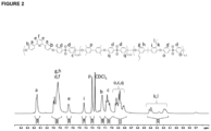
Figure 2 : 1H-NMR spectrum of the precursor polymer,Copolymer 1. -
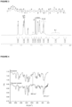
Figure 3 : 1H-NMR spectrum of the brominated polymer,Copolymer 2. -
Figure 4 : ATR spectra of the precursor polymer (upper curve) and Br-polymer (lower curve). -
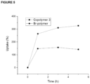
Figure 5 : Doping in 85% H3PO4 of the brominated polymer (circle symbol) and copolymer 3 (square symbol) as a function of time. -
Figure 6 (A-B): Bilayer membranes with the structures of the polymers used in each layer. -
Figure 7 :ATR spectra copolymer 3, the top layer of the bilayer membrane, the bottom layer of the bilayer membrane and the brominated polymer. -
Figure 8 :ATR spectra copolymer 3, the top layer of the bilayer membrane, the bottom layer of the bilayer membrane and the brominated polymer. The left spectra show the region at 1600-1400 cm-1, while the right spectra show the region at 1000-700 cm-1. -
Figure 9 : Doping in 85% H3PO4 of the brominated polymer (circle symbol), copolymer 3 (square symbol) and the bilayer membrane (triangle) as a function of time. -
Figure 10 (A-C) : Dimensional stability of a bilayer membrane before doping (Fig. 10A ) after 1 hour (Fig. 10B ) and5 hours (Fig. 10C ) of doping in H3PO4 at 120 0C. - It is a subject of the present disclosure to provide novel, high temperature polymer electrolyte membranes, methods of production of such membranes and uses thereof.
- High temperature polymer electrolyte membrane fuel cells (HT- PEMFC) offer certain advantages when compared to low temperature polymer electrolyte membrane fuel cells (LT- PEMFC) such as, (a)high operation temperature that allows the use of impure hydrogen with high CO content, (b) system simplification, and (c)high combined heat and power efficiency. For instance, a LT-PEMFC has a very low tolerance to impurities in fuel, thus requiring 99.99999% pure hydrogen which is costly to produce. The heat produced from the LT-PEMFC is also of a low temperature and thus is difficult to transfer away for use in other processes. These drawbacks can be overcome through the use of HT- PEMFCs. In order to achieve a fuel cell operation in temperatures above 100 0C, electrolytes having high ionic conductivity are desired and are mainly based on polymers imbibed with a strong acid such as phosphoric acid (PA). These doped membranes should combine high acid uptake ability with mechanical robustness, especially at the operation temperature of around 160 to 200 0C. Aromatic polymers such as polybenzimidazole and aromatic polyethers are the most commonly used polymers. Polybenzimidazole (PBI)-type polymers provide high acid uptake and moderate mechanical stability of the doped membranes, while the latter show lower acid uptake and higher operation temperatures. Although the high operation temperature enables better reaction kinetics for the catalyst on both electrodes, the high amount of phosphoric acid on the cathode restricts the operation, demanding high catalyst (i.e.platinum) loading. Moreover, the extensive swelling of the polymeric membrane on the x-y axes during phosphoric acid doping, may create problems in the event of deswelling due to the increase of the operation temperature, leading to condensation of phosphoric acid. Stabilization of the polymer electrolyte membranes has been performed using crosslinking, enabling thus the increase of operation temperature (Kallitsis et al; Journal of Power Sources; 2028; 379:144-154).
- The inventors of the present disclosure have managed to resolve these issues by inventing bilayer polymer electrolyte membranes which combine a bottom crosslinked layer with lower acid uptake and a second top layer having the ability to absorb a high amount of acid, acting as an acid reservoir. Such a bilayer membrane format can act both as a template for controlling the membrane swelling/deswelling, as well as prevent catalyst flooding with phosphoric acid on the cathode side. Generally, in a fuel cell, phosphoric acid in the PA-doped PEM would migrate to the cathode and anode during the process of constructing the membrane electrode assembly. Thus, the phosphoric acid adsorbed by the anode would migrate to the cathode through the membrane. To enhance the retention of PA, the materials used for the cathode should have low PA adsorption, while the materials applied for the anode should have high PA adsorption. It is generally known that the affinity of PA to water is close to the affinity of PA to polymers, leading to an easy leakage of PA from the polymeric membrane, due its interaction with water, at lower temperatures and high humidity during the cell start-up and shut-down. Moreover, in the case of PBI, a large amount of loosely bound PA molecules is used in the PA/PBI membranes, which helps to improve the proton conductivity. Thus, the loosely bound PA inside the membrane could easily leach out with increased water presence, due to the very weak interaction between the loosely bound PA and the polymer. When a PA/PBI membrane is exposed to a humid environment, water molecules penetrate into the PA/PBI system and take loosely bound PA molecules away from the system (PA leaching). However, recently used copolymers (Charalampopoulos, C.; Kallitsis, K. J.; Anastasopoulos, C.; Daletou, M. K.; Neophytides, S. G.; Andreopoulou, A. K.; Kallitsis, J. K. Crosslinked Polymer Electrolytes of High Pyridine Contents for HT-PEM Fuel Cells. Int J Hydrogen Energy 2020, 45 (60), 35053-35063. https://doi.ora/10.1016/i.iihvdene.2020.06.004 ). bearing 2,5 and 2,6 pyridine main chain units (e.g. UNIT A and UNIT B respectively) have shown higher acid retention, mainly due to the stronger interaction of the PA molecules with pyridine units and also due to the lower acid uptake, which reduces the amount of the loosely bound PA as shown in the
Figure 1 .
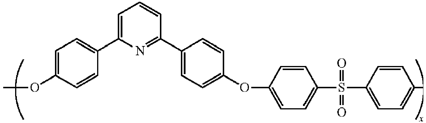
- In order to achieve the formation of bilayer polymer electrolyte membranes with optimized properties, the inventors utilized main chain aromatic polyether copolymers containing main chain pyridine units (APEPY), with various pyridine content, in order to control acid uptake. The bilayer membrane consists of a bottom layer of a self cross linkable copolymer, having low pyridine content and bearing side double bond moieties functionalized with bromine, for quick thermal crosslinking during casting, and of a second layer of a linear copolymer, with high pyridine content. More specifically a self crosslinkable APEPY with low pyridine content (e.g. Br-polymer, Copolymer 2) was used for the first layer, while a linear APEPY with high pyridine content (e.g. Copolymer 3) and high phosphoric acid uptake was used as the top layer. The formation of such a bilayer requires a balanced crosslinking of the first layer and deposition of the solution of the second layer in order to avoid dissolution, shrinkage, and even skin formation resulting in delamination of the two layers during phosphoric acid doping and membrane operation.


- In one aspect, the present disclosure relates to a bilayer polymer electrolyte membrane comprising a bottom crosslinked copolymer layer with low pyridine content for lower acid uptake and a top linear copolymer layer, with high pyridine content, for higher acid uptake.
- In one embodiment said bilayer polymer electrolyte membrane comprises a bottom crosslinked copolymer layer with low pyridine content for lower acid uptake, wherein said acid is phosphoric acid, and a top linear copolymer layer, with high pyridine content for higher acid uptake, wherein said acid is phosphoric acid.
- In one embodiment said bilayer polymer electrolyte membrane comprises a bottom crosslinked copolymer layer with low pyridine content for lower acid uptake, wherein said acid is phosphoric acid, and a top linear copolymer layer, with high pyridine content for higher acid uptake, wherein said acid is phosphoric acid, and wherein the acid uptake of said bilayer membrane is about 250 to 350 % wt.
- In one embodiment said bilayer polymer electrolyte membrane comprises a bottom crosslinked copolymer layer said
copolymer being copolymer 2 of the formula
and a top linear copolymer layer, with high pyridine content for higher acid uptake, wherein said acid is phosphoric acid. - In one embodiment said bilayer polymer electrolyte membrane comprises a bottom crosslinked copolymer layer with low pyridine content for lower acid uptake said acid being phosphoric acid and a top linear copolymer layer said
copolymer being copolymer 3 of the formula
- In one embodiment said bilayer polymer electrolyte membrane comprises a bottom crosslinked copolymer layer said
copolymer being copolymer 2 of the formula
and a top linear copolymer layer saidcopolymer being copolymer 3 of the formula
- In one embodiment said bilayer polymer electrolyte membrane comprises a bottom crosslinked copolymer layer said
copolymer being copolymer 2 of the formula
copolymer being copolymer 3 of the formula
- In one embodiment said bilayer polymer electrolyte membrane consists of a bottom crosslinked copolymer layer said
copolymer being copolymer 2 of the formula
copolymer being copolymer 3 of the formula
- In another aspect the present disclosure relates to a method of producing a bilayer polymer electrolyte membrane comprising the steps of
- synthesizing a first copolymer with low pyridine content for lower acid uptake in order to form the bottom layer of said membrane
- adding a second copolymer with high pyridine content for higher acid uptake on top of said first copolymer forming the bottom layer of said membrane.
- In one embodiment said method comprises the steps of
- synthesizing a first copolymer with low pyridine content for lower acid uptake in order to form the bottom layer of said membrane, wherein said first copolymer is
copolymer 2 of the formula
- adding a second copolymer with high pyridine content for higher acid uptake on top of said first copolymer forming the bottom layer of said membrane.
- In one embodiment said method comprises the steps of
- synthesizing a first copolymer with low pyridine content for lower acid uptake in order to form the bottom layer of said membrane
- adding a second copolymer with high pyridine content for higher acid uptake on top of said first copolymer forming the bottom layer of said membrane, wherein said second copolymer is
copolymer 3
- In one embodiment said method comprises the steps of
- synthesizing a first copolymer with low pyridine content for lower acid uptake in order to form the bottom layer of said membrane, wherein said first copolymer is
copolymer 2 of the formula
- adding a second copolymer with high pyridine content for higher acid uptake on top of said first copolymer forming the bottom layer of said membrane, wherein said second copolymer is
copolymer 3 of the formula
- In one embodiment said method comprises the steps of
- mixing
copolymer 1 of the formula
with N-bromosuccinimide and chloroform in order to synthesizecopolymer 2 of the formula
- forming a first bottom membrane layer consisting of
copolymer 2 - adding
copolymer 3 of the formula
copolymer 2. - In one embodiment said method comprises the steps of
- mixing
copolymer 1 of the formula
with N-bromosuccinimide and chloroform in order to synthesizecopolymer 2 of the formula
- dissolving
copolymer 2 in N-methyl-2-pyrrolidone - pouring said dissolved polymeric solution in a mold or surface
- drying of said polymeric solution so that the solvent is removed and a gel-like membrane is formed
- adding
copolymer 3 of the formula
dissolved in N,N-dimethylacetamide on top of said first bottom gel like membrane layer consisting ofcopolymer 2 - drying of said membrane on top of which
copolymer 3 was added, so that a bilayer membrane is formed. - In one embodiment said method comprises the steps of
- mixing
copolymer 1 of the formula
with N-bromosuccinimide and chloroform in order to synthesizecopolymer 2 of the formula
- dissolving
copolymer 2 in N-methyl-2-pyrrolidone - pouring said dissolved polymeric solution in a mold or surface
- drying of said polymeric solution so that the solvent is partially removed and a gel-like membrane is formed
- adding
copolymer 3 of the formula
dissolved in N,N-dimethylacetamide, on top of said first bottom gel like membrane layer consisting ofcopolymer 2 - drying of said membrane on top of which
copolymer 3 was added, so that a bilayer membrane is formed. - immersing said bilayer membrane into a solution of phosphoric acid so that a phosphoric acid doped bilayer membrane is formed.
- In an even further aspect the present invention relates to a bilayer polymer electrolyte membrane directly obtainable or obtained by a method of the invention.
- In another aspect the present disclosure relates to a use of a bilayer polymer electrolyte membrane of the invention for the production of a fuel cell and/or an electrolyzer and/ or a redox flow battery.
- In another aspect the present invention relates to a use of a bilayer polymer electrolyte membrane of the invention for the production of a fuel cell, wherein said fuel cell is a high temperature polymer electrolyte membrane fuel cell.
- Unless otherwise defined, scientific and technical terms used herein have the meanings that are commonly understood by those of ordinary skill in the art. In the event of any latent ambiguity, definitions provided herein take precedent over any dictionary or extrinsic definition.
- The term "doping level" in the context of the present disclosure refers to weight per cent % of the acid, preferably phosphoric acid, absorbed of each membrane of the invention.
- The term "fuel cell" in the context of the present disclosure refers to an electrochemical device that converts the chemical energy of a fuel (often hydrogen) and an oxidizing agent (often oxygen) into electricity through a pair of redox reactions. Fuel cells are different from most batteries in requiring a continuous source of fuel and oxygen (usually from air) to sustain the chemical reaction, whereas in a battery the chemical energy usually comes from substances that are already present in the battery. Fuel cells can produce electricity continuously for as long as fuel and oxygen are supplied.
- The terms "doped" and "imbibed" in the context of the present disclosure are used interchangeably. The term "about" or "approximately" means the mentioned value +/-10%, for example about 10 shall mean 9 to 11.
- Unless otherwise required by context, singular terms shall include pluralities and plural terms shall include the singular. The use of "or" means "and/or" unless stated otherwise. The use of the term "including," as well as other forms, such as "includes" and "included," is not limiting.
- While the present invention has been described with reference to the specific embodiments thereof, it should be understood by those skilled in the art that various changes may be made and equivalents may be substituted without departing from the true spirit and scope of the invention using this disclosure as a guide. Having now described certain embodiments in detail, the same will be more clearly understood by reference to the following examples, which are included for purposes of illustration only and are not intended to be limiting.
- Starting materials and reagents disclosed below are known to those skilled in the art, are commercially available and/or can be prepared using well-known techniques.
- For the preparation of the precursor polymer,
Copolymer 1, in a degassed round-bottom flask, equipped with a magnetic stirrer and a Dean-Stark trap, 2,6-bis(4-hydroxyphenyl)pyridine (7.6 mmol, 2.02 g), 3,3',5,5'-tetramethylbiphenyl-4,4'-diol (7.6 mmol, 1.88 g), 2,2'-diallylbisphenol A (6.6 mmol, 2.03 g), bis(4-fluorophenyl)sulfone (2.2 mmol, 5.63 g), K2CO3 (6 g), N,N-dimethylacetamide (DMAc) (80 ml) and toluene (10 ml) were added and the mixture, after it was degassed and purged with argon, was heated at 150 0C for 4h. Then, the temperature was raised to 170 0C, and the azeotropic mixture of toluene/water was extracted. After the completion of the reaction, the mixture was poured in a 5-fold excess of ethanol, to precipitate the polymer. The product was then filtered and washed thoroughly with ethanol and water. Finally, it was dried at 60 0C under vacuum for up to 2 days.
- The precursor polymer was designed to combine a moderate phosphoric acid doping (by using small percentages of pyridine), with a chemical modification ability (imparted by the 2,2'-diallylbisphenol A comonomer) and was the basis of the crosslinked membrane bottom layer. The monomers used for the preparation of the precursor polymer comprise the commercially available bis(4-fluorophenyl)sulfone (diFSO2), 3,3',5,5'-tetramethylbiphenyl-4,4'-diol (TMdiol), 2,2'-diallylbisphenol A (DBdiol) and the
monomer 2,6-bis(4-hydroxyphenyl)pyridine (HOpy) that was developed previously by the inventors (Gourdoupi et al; 2003; Chem. Mater.; 15: 5044-5050). The ratio of the monomers TMdiol, DBdiol, and HOpy varied in orderto fine-tune the high uptake property of the pyridine moiety, and the density of the crosslinking sites, imparted by the DBdiol moiety. The molecular weight of the synthesized precursor polymer was exceptionally high (up to Mn=110,000 Da and Mw=253,000 Da). The high MWs are critical to provide high mechanical stability on the doped membrane. The polymerization was repeated several times showing the reproducibility of the very high molecular weight polymers as shown in Table 1.Table 1. Gel permeation chromatography (GPC) characterization of the precursor polymer. Mna (Da) Mwb (Da) Dispc Copolymer 1A 110000 253000 2.3 Copolymer 1B 84000 204000 2.4 Copolymer 1C 80000 183000 2.3 Copolymer 1D 98000 235000 2.4 - a) Mn=number-average molecular weight,
- b) Mw= weight average molecular weight,
- c) Disp=polydispersity, Mw/Mn
- Moreover, the precursor polymer is highly soluble in common organic solvents. As a result, its structure was confirmed by hydrogen-1 nuclear magnetic resonance (1H-NMR). As it can be seen in
Figure 2 , the proton peaks at about 6.3 ppm confirm the existence of the double bonds. It is notable that in this case, the multiplicity of the peaks is complicated, due to the rearrangement of the double bonds, because of the existence of K2CO3 in the polymerization reaction mixture. - For the preparation of the
Copolymer 2, in a degassed round-bottom flask, the precursor polymer of Example 1 (4.13 mmol, 2 g), N-bromosuccinimide (3,73 mmol, 0,7 g), and chloroform (200 ml) were added and the mixture, after it was degassed and purged with argon, was heated at 70 0C for 16h. After completion of the reaction, the mixture was poured in a 5-fold excess of ethanol, to precipitate the polymer. The product was then filtered and washed thoroughly with ethanol and water. Finally, it was dried at 60 0C under vacuum for up to 2 days.
- In order to obtain a self-crosslinkable membrane, a bromomethylenic group was used. In this case, the benzene rings in the polymeric structure could attack the bromomethylenic groups in the DBdiol moieties, through a Friedel-Crafts electrophilic substitution reaction. To achieve this, we first brominated the double bonds of the DBdiol moieties, using NBS in chloroform. By carefully tuning the temperature of the reaction, we could avoid the immediate crosslinking of the polymeric chains in the reaction mixture. After obtaining the precipitated polymer, self-crosslinking could occur, during the casting process, without the use of any additional reagents. The structure of the brominated polymer, was confirmed by 1H-NMR in CDCl3 (
Figure 3 ). - As it can be seen in
Figure 3 , the spectrum has few differences compared to the precursor polymer, the basic one being the peaks of the hydrogens of the double bonds (k and l), that appear in reduced quantities. This could be explained by the substitution of the hydrogens by bromine atoms. - The successful bromination of the precursor polymer was also confirmed by Attenuated total reflection (ATR) spectroscopy. As it can be seen in
Figure 4 , the characteristic peak correlated to the double bonds of the DBdiol moiety at 965 cm-1, confirming the existence of the double bonds after the bromination reaction, ruling out an addition reaction of HBr. Additionally, a shoulder that appears at 523 cm-1 could be attributed to the C-Br bonds that forms after the bromination reaction, as it is not present in the spectrum of the pre-polymer. - For the preparation of the single layer membrane, 230 mg of the Br-polymer,
Copolymer 2 was dissolved in 4.6 ml N-Methyl-2-pyrrolidone (NMP). The solution was transferred to a Petri dish (5.5 cm diameter) and was left at 90 °C until complete removal of the solvent. The membrane was peeled-off and was subsequently washed with deionized water. Then the membrane was dried at 60 0C for 16h under high vacuum. The membrane thickness was 60 µm. - For the preparation of the bilayer membranes consisting of
Copolymer 2 andCoplymer 3, 1 g ofCoplymer 2 was dissolved in 60 mL of N-methyl-2-pyrrolidone (NMP). The polymeric solution was then transferred in a glass mold (16x18 cm2 ) and was left for 5-7h to remove most of the solvent at 90 °C. When the first layer solution condenses to form a gel-like sticky membrane, the second layer of copolymer 3 [prepared as described in Charalampopoulos, C.; Kallitsis, K. J.; Anastasopoulos, C.; Daletou, M. K.; Neophytides, S. G.; Andreopoulou, A. K.; Kallitsis, J. K. Crosslinked Polymer Electrolytes of High Pyridine Contents for HT-PEM Fuel Cells. Int J Hydrogen Energy 2020, 45 (60), 35053-35063. https://doi.org/10.1016/j.ijhydene.2020.06.004.] dissolved in N,N-Dimethylacetamide (DMA, 1.5g in 70 ml), and was also added in the glass mold to create the double layer membrane. The system was left to evaporate for up to 16 hours at 90 °C. After complete removal of the solvents, the self-standing membrane was peeled off the mold and was washed thoroughly with deionized water. Then it was dried for 12 h at 60 °C under high vacuum. The thickness of the bilayer membrane was 80-100 µm. - Then the bilayer membrane was doped with phosphoric acid. For this reason, the membrane was immersed in an 85% phosphoric acid solution at 120 0C. The weight gain of the samples was calculated at various time intervals (1h,3h, 5h, 1d), after wiping the samples and weighing them. The doping level is defined as the weight percent of the phosphoric acid of each membrane.
- The same doping process was also followed for the
single layer Copolymer 2 membrane andCopolymer 3 membrane alone, so that the single and bilayer membranes can be compared. - In the process of stabilizing the bilayer membrane through thermal crosslinking during casting, the casting of single layer membranes was first evaluated in order to measure the uptake of phosphoric acid. These single membranes, because of their compositional characteristics and their crosslinking during casting, show low doping ability that peaked at 150% at 120 0C. These can be seen in Table 2. In order to compare the performance of the brominated polymer,
Copolymer 2 and assess its performance and its crosslinking ability, we also cast a membrane ofcopolymer 3 with high pyridine content that has been thoroughly studied [Charalampopoulos, C.; Kallitsis, K. J.; Anastasopoulos, C.; Daletou, M. K.; Neophytides, S. G.; Andreopoulou, A. K.; Kallitsis, J. K. Crosslinked Polymer Electrolytes of High Pyridine Contents for HT-PEM Fuel Cells. Int J Hydrogen Energy 2020, 45 (60), 35053-35063. https://doi.org/10.1016/j.ijhydene.2020.06.004]. It is evident from its uptake (up to 330 wt%) that the cross-linking strategy followed successfully limits the uptake of the brominated polymer membrane. In addition, the crosslinking of the brominated polymer, succeeds at limiting the dimensional stability of the membrane. We can see that while forcopolymer 3 the dimensional swelling in the x-y axes is in the range of 10-20%, its z axis swells up to 100%. In contrast, the z-axis swelling of the brominated polymer remains relatively low, at 40%, while the x,y-axis swelling is in the same range ascopolymer 3.Table 2. Doping of the brominated polymer and copolymer 3 in 85% H3PO4 at 120 0C.1h 3h 5h DL (wt%) Swx* (%) DL (wt%) Swx (%) DL (wt%) Swx (%) Swy** (%) Swy (%) Swy (%) Swz*** (%) Swz (%) Swz (%) Br-polymer 150 20 150 20 150 20 20 20 30 40 40 40 Copolymer 3260 20 310 20 330 20 10 20 20 70 90 100 *Swx: swelling in x axis
**Swy: swelling in y axis
***Swz: swelling in z axis
DL: doping level - The doping level of the two polymeric membranes can also be seen visually in
Figure 5 . The same methodology was followed to construct the Bilayer membranes' bottom layer ofCopolymer 2 that was subsequently followed by the casting of the second layer composed ofCopolymer 3, a high pyridine content aromatic polyether copolymers showing high phosphoric acid uptake (Charalampopoulos, C.; Kallitsis, K. J.; Anastasopoulos, C.; Daletou, M. K.; Neophytides, S. G.; Andreopoulou, A. K.; Kallitsis, J. K. Crosslinked Polymer Electrolytes of High Pyridine Contents for HT-PEM Fuel Cells. Int J Hydrogen Energy 2020, 45 (60), 35053-35063. https://doi.org/10.1016/j.ijhydene.2020.06.004). The bilayer structure is presented schematically inFigure 6 and was casted on a glass substrate. - By comparing the solubilities between the two single layer membranes to the bilayer membrane (Table 3), it is evident that the crosslinking strategy is successful, as Br-polymer is highly insoluble in DMAc, while
copolymer 3 is completely soluble. The bilayer membrane as expected shows a small insoluble fraction of 15%, that could be attributed to the crosslinked bottom layer.Table 3. Solubility of the membranes in DMAc. Insoluble Fraction % Soluble Fraction % Bilayer Before Doping 15 85 After Doping 76 24 Br-polymer Before Doping 65 35 After Doping 100 0 Copolymer 3Before Doping 0 100 After Doping 63 37 - Moreover, the single and bilayer membranes were characterised via ATR spectroscopy (
Figure 7 ). As it can be seen inFigure 7 , the spectra in general present similarities, mainly attributed to the somewhat similar structures of the polymers. However, there are two main regions at 1400-1500 cm-1 and 900-800 cm-1 where there are some differences in the spectra of the top and bottom layers of the bilayer membrane. In particular, the bottom layer that consists of Br-polymer, has peaks at 1480 cm-1 and 1450 cm-1 of the same intensity, while the top layer andCopolymer 3, both have two peaks of the same intensity at these wavenumbers. At 800 cm-1 Br-polymer has a large peak that can also be observed at the bottom layer of the bilayer membrane spectrum. This same peak is appeared for the top layer andCopolymer 3. In general, in the region of 870-800 cm-1 the brominated polymer along with thebottom layer display 3 peaks of the same intensity, while the top layer withCopolymer 3display 2 peaks of the same intensity, along with a fainter one. - Additionally, different bilayer membranes, namely with different ratios of
Copolymer 2 andCopolymer 3, were studied in terms of their PA uptake and the results are shown in Table 4. As it can be seen, the PA uptake of the bilayer membranes are similar or lower to the PA uptake level of theCopolymer 3 membrane, depending on the ratio of the two copolymers. After 5 hours at 120 °C all membranes have reached a somewhat steady doping level in the range of 300-350%.Table 4. Doping of the brominated polymer, copolymer 3 and the bilayer membranes in 85% H3PO4 and at 120 0C1h 3h 5h DL (wt%) Swx (%) DL (wt%) Swx (%) DL (wt%) Swx (%) Swy (%) Swy (%) Swy (%) Swz (%) Swz (%) Swz (%) Br-polymer 150 20 150 20 140 20 20 30 20 40 40 40 Copolymer 3260 20 310 20 330 20 10 20 20 70 90 100 Bilayer 1250 0 270 20 300 20 20 30 30 70 80 83 Bilayer 2185 20 225 20 260 20 40 40 40 50 60 60 Bilayer 3238 25 283 30 284 30 20 20 20 50 60 70 Bilayer 4320 25 334 25 350 25 30 30 30 70 70 70 Bilayer 5226 20 276 25 345 25 25 25 30 140 140 160
Claims (11)
- A bilayer polymer electrolyte membrane characterized in that said membrane comprises a bottom crosslinked copolymer layer said copolymer being copolymer 2 of the formula


- The bilayer polymer electrolyte membrane of claim 1 wherein said membrane comprises a bottom crosslinked copolymer layer said copolymer being copolymer 2 of the formula


- The bilayer polymer electrolyte membrane of any one of claims 1 or 2, wherein said membrane comprises a bottom crosslinked copolymer layer said copolymer being copolymer 2 of the formula


- A method of producing a bilayer polymer electrolyte membrane, said method comprising the steps of- synthesizing a first copolymer with low pyridine content for lower acid uptake in order to form the bottom layer of said membrane, wherein said first copolymer is copolymer 2 of the formula
 - adding a second copolymer with high pyridine content for higher acid uptake on top of said first copolymer forming the bottom layer of said membrane, wherein said second copolymer is copolymer 3 of the formula
- The method of claim 4, characterized in that said method comprises the steps of- synthesizing a first copolymer with low pyridine content for lower acid uptake in order to form the bottom layer of said membrane, wherein said first copolymer is copolymer 2 of the formula
 - adding a second copolymer with high pyridine content for higher acid uptake on top of said first copolymer forming the bottom layer of said membrane, wherein said second copolymer is copolymer 3 of the formula
- The method of any one of claims 4 or 5 characterized in that said method comprises the steps of- mixing copolymer 1 of the formula

with N-bromosuccinimide and chloroform in order to synthesize copolymer 2 of the formula - forming a first bottom membrane layer consisting of copolymer 2- adding copolymer 3 of the formula
- The method of any one of claims 4 to 6 characterized in that said method comprises the steps of- mixing copolymer 1 of the formula

with N-bromosuccinimide and chloroform in order to synthesize copolymer 2 of the formula - dissolving copolymer 2 in N-methyl-2-pyrrolidone- pouring said dissolved polymeric solution in a mold or surface- drying of said polymeric solution so that the solvent is removed and a gel-like membrane is formed- adding copolymer 3 of the formula
dissolved in dimethylacetamide, on top of said first bottom gel like membrane layer consisting of copolymer 2- drying of said membrane on top of which copolymer 3 was added, so that a bilayer membrane is formed. - The method of any one of claims 4 to 7 characterized in that said method comprises the steps of- mixing copolymer 1 of the formula

with N-bromosuccinimide and chloroform in order to synthesize copolymer 2 of the formula - dissolving copolymer 2 in N-methyl-2-pyrrolidone- pouring said dissolved polymeric solution in a mold or surface- drying of said polymeric solution so that the solvent is removed and a gel-like membrane is formed- adding copolymer 3 of the formula
dissolved in dimethylacetamide on top of said first bottom gel like membrane layer consisting of copolymer 2- drying of said membrane on top of which copolymer 3 was added, so that a bilayer membrane is formed.- immersing said bilayer membrane into a solution of phosphoric acid so that a phosphoric acid doped bilayer membrane is formed. - A bilayer polymer electrolyte membrane directly obtainable or obtained by the method of anyone of claims 4 to 8.
- Use of a bilayer polymer electrolyte membrane of anyone of claims 1 to 3 or 9 for the production of a fuel cell and/or an electrolyzer and/ or a redox flow battery.
- Use of a bilayer polymer electrolyte membrane of claim 10, wherein said fuel cell is a high temperature polymer electrolyte membrane fuel cell.
Priority Applications (1)
| Application Number | Priority Date | Filing Date | Title |
|---|---|---|---|
| EP23215092.0A EP4567943A1 (en) | 2023-12-07 | 2023-12-07 | Bilayer membranes composed of two interconnected layers with different phosphoric acid doping ability |
Applications Claiming Priority (1)
| Application Number | Priority Date | Filing Date | Title |
|---|---|---|---|
| EP23215092.0A EP4567943A1 (en) | 2023-12-07 | 2023-12-07 | Bilayer membranes composed of two interconnected layers with different phosphoric acid doping ability |
Publications (1)
| Publication Number | Publication Date |
|---|---|
| EP4567943A1 true EP4567943A1 (en) | 2025-06-11 |
Family
ID=89122013
Family Applications (1)
| Application Number | Title | Priority Date | Filing Date |
|---|---|---|---|
| EP23215092.0A Pending EP4567943A1 (en) | 2023-12-07 | 2023-12-07 | Bilayer membranes composed of two interconnected layers with different phosphoric acid doping ability |
Country Status (1)
| Country | Link |
|---|---|
| EP (1) | EP4567943A1 (en) |
Citations (1)
| Publication number | Priority date | Publication date | Assignee | Title |
|---|---|---|---|---|
| US20080160378A1 (en) * | 2006-09-12 | 2008-07-03 | Advent Technologies Sa | Novel poly(arylene ether) copolymers containing pyridine units as proton exchange membranes |
-
2023
- 2023-12-07 EP EP23215092.0A patent/EP4567943A1/en active Pending
Patent Citations (1)
| Publication number | Priority date | Publication date | Assignee | Title |
|---|---|---|---|---|
| US20080160378A1 (en) * | 2006-09-12 | 2008-07-03 | Advent Technologies Sa | Novel poly(arylene ether) copolymers containing pyridine units as proton exchange membranes |
Non-Patent Citations (8)
| Title |
|---|
| CHARALAMPOPOULOS, C.KALLITSIS, K. J.ANASTASOPOULOS, C.DALETOU, M. K.NEOPHYTIDES, S. G.ANDREOPOULOU, A. K.KALLITSIS, J. K.: "Crosslinked Polymer Electrolytes of High Pyridine Contents for HT-PEM Fuel Cells", INT J HYDROGEN ENERGY, vol. 45, no. 60, 2020, pages 35053 - 35063, XP086370100, Retrieved from the Internet <URL:https://doi.org/10.1016/j.ijhydene.2020.06.004.> DOI: 10.1016/j.ijhydene.2020.06.004 |
| GOURDOUPI ET AL., CHEM. MATER., vol. 15, 2003, pages 5044 - 5050 |
| GUO ZUNMIN ET AL: "Recent advances in phosphoric acid-based membranes for high-temperature proton exchange membrane fuel cells", JOURNAL OF ENERGY CHEMISTRY, ELSEVIER, AMSTERDAM, NL, vol. 63, 15 July 2021 (2021-07-15), pages 393 - 429, XP086917545, ISSN: 2095-4956, [retrieved on 20210715], DOI: 10.1016/J.JECHEM.2021.06.024 * |
| JEONG ET AL., J POWER SOURCES, vol. 363, 2017, pages 365 - 374, Retrieved from the Internet <URL:https://doi.ora/10.1016/i.ipowsour.2017.07.109> |
| KALLITSIS ET AL., JOURNAL OF POWER SOURCES, vol. 2028, no. 379, pages 144 - 154 |
| KONSTANTINIA D. PAPADIMITRIOU ET AL: "Cross-Linking of Side Chain Unsaturated Aromatic Polyethers for High Temperature Polymer Electrolyte Membrane Fuel Cell Applications", MACROMOLECULES, vol. 44, no. 12, 28 June 2011 (2011-06-28), pages 4942 - 4951, XP055006741, ISSN: 0024-9297, DOI: 10.1021/ma200351z * |
| PEFKIANAKIS ELEFTERIOS K ET AL: "Novel polymer electrolyte membrane , based on pyridine containing poly(ether sulfone), for application in high-temperature fuel cells", MACROMOLECULAR RAPID COMMUNICATIONS, WILEY-VCH, DE, vol. 26, no. 21, 1 January 2005 (2005-01-01), pages 1724 - 1728, XP002495312, ISSN: 1022-1336, DOI: 10.1002/MARC.200500540 * |
| YANG ET AL., JOURNAL OF POWER SOURCES, vol. 103, 2001, pages 1 - 9 |
Similar Documents
| Publication | Publication Date | Title |
|---|---|---|
| Shi et al. | Acid doped branched poly (biphenyl pyridine) membranes for high temperature proton exchange membrane fuel cells and vanadium redox flow batteries | |
| Chen et al. | Tunable multi-cations-crosslinked poly (arylene piperidinium)-based alkaline membranes with high ion conductivity and durability | |
| Park et al. | Chemically durable polymer electrolytes for solid-state alkaline water electrolysis | |
| US6124060A (en) | Solid polymer electrolytes | |
| US10224562B2 (en) | Method for producing polymer electrolyte molded article, polymer electrolyte material, polymer electrolyte membrane, and polymer electrolyte fuel cell | |
| CN101003637B (en) | Polymer electrolyte membrane, method of preparing the same and fuel cell employing the same | |
| US6767664B2 (en) | Proton conducting polymer, method for producing the same, solid polymer electrolyte and electrode | |
| US20040097695A1 (en) | Proton-conducting polymer with acid groups in side chains, preparation method thereof, polymer membrane manufactured using the polymer, and fuel cell using the polymer membrane | |
| Li et al. | Anion conductive piperidinium based poly (ether sulfone): Synthesis, properties and cell performance | |
| EP2345682A2 (en) | Polymer electrolyte membrane | |
| CN102640338A (en) | polymer electrolyte membrane, membrane-electrode assembly, and solid polymer fuel cell | |
| EP2134768B1 (en) | Proton conducting aromatic polyether type copolymers bearing main and side chain pyridine groups and use thereof in proton exchange membrane fuel cells | |
| JP4537065B2 (en) | Proton conducting electrolyte membrane, method for producing the same and use in fuel cell | |
| JP2025517699A (en) | Novel branch-containing poly(arylpiperidinium) copolymer ionomer, anion exchange membrane, and method for producing same | |
| EP2147943A1 (en) | Crosslinked aromatic polymer, polymer electrolyte, catalyst ink, polymer electrolyte membrane, membrane-electrode assembly and fuel cell | |
| US20100081030A1 (en) | Method for producing polymer electrolyte membrane and polymer electrolyte membrane | |
| KR20120061156A (en) | Polybenzimidazole Based Polymer Having Conductivity of Hydroxyl Ion and Method for Preparing the Same, Electrolyte Membrane and Fuel Cell Using the Same | |
| KR101202331B1 (en) | A multiblock copolymer, a method for preparing the multiblock copolymer, a polymer electrolyte membrane prepared from the multiblock copolymer, a method for preparing the polymer electrolyte membrane and a fuel cell employing the polymer electrolyte membrane | |
| KR100948347B1 (en) | Method for producing partially crosslinked hydrogen ion conductive polymer electrolyte membrane, membrane-electrode assembly using partially crosslinked polymer electrolyte membrane prepared therefrom, and fuel cell employing the same | |
| US20070148520A1 (en) | Novel metal (III) -chromium-phosphate complex and use thereof | |
| KR20120009789A (en) | Proton conductive polymer, polymer electrolyte membrane, cation exchange resin, cation exchange membrane, and method for producing the polymer | |
| JP5626960B2 (en) | POLYMER ELECTROLYTE, PROCESS FOR PRODUCING THE SAME AND USE THEREOF | |
| KR100738788B1 (en) | Polybenzimidazole-benzamide copolymer and preparation method thereof, electrolyte membrane prepared therefrom and preparation method thereof | |
| KR100773322B1 (en) | Polymer electrolyte membrane for fuel cell containing crosslinked PI and method for manufacturing same | |
| CN117913330B (en) | Sulfonated polybenzothiazole-polybenzimidazole block cross-linked proton exchange membrane and preparation method thereof |
Legal Events
| Date | Code | Title | Description |
|---|---|---|---|
| PUAI | Public reference made under article 153(3) epc to a published international application that has entered the european phase |
Free format text: ORIGINAL CODE: 0009012 |
|
| STAA | Information on the status of an ep patent application or granted ep patent |
Free format text: STATUS: THE APPLICATION HAS BEEN PUBLISHED |
|
| AK | Designated contracting states |
Kind code of ref document: A1 Designated state(s): AL AT BE BG CH CY CZ DE DK EE ES FI FR GB GR HR HU IE IS IT LI LT LU LV MC ME MK MT NL NO PL PT RO RS SE SI SK SM TR |
|
| STAA | Information on the status of an ep patent application or granted ep patent |
Free format text: STATUS: REQUEST FOR EXAMINATION WAS MADE |
|
| 17P | Request for examination filed |
Effective date: 20251113 |
|
| GRAP | Despatch of communication of intention to grant a patent |
Free format text: ORIGINAL CODE: EPIDOSNIGR1 |
|
| STAA | Information on the status of an ep patent application or granted ep patent |
Free format text: STATUS: GRANT OF PATENT IS INTENDED |
|
| RIC1 | Information provided on ipc code assigned before grant |
Ipc: H01M 8/1053 20160101AFI20260302BHEP Ipc: H01M 8/1027 20160101ALI20260302BHEP Ipc: C25C 7/04 20060101ALI20260302BHEP Ipc: H01M 8/103 20160101ALI20260302BHEP Ipc: H01M 8/1032 20160101ALI20260302BHEP Ipc: H01M 8/18 20060101ALI20260302BHEP Ipc: C25B 13/08 20060101ALI20260302BHEP Ipc: H01M 8/10 20160101ALN20260302BHEP |
|
| INTG | Intention to grant announced |
Effective date: 20260401 |
|
| RIN1 | Information on inventor provided before grant (corrected) |
Inventor name: KALLITSIS, IOANNIS Inventor name: ANDREOPOULOU, EKATERINI Inventor name: ANDRIKOPOULOS, KONSTANTINOS |
|
| GRAS | Grant fee paid |
Free format text: ORIGINAL CODE: EPIDOSNIGR3 |
|
| GRAA | (expected) grant |
Free format text: ORIGINAL CODE: 0009210 |
|
| STAA | Information on the status of an ep patent application or granted ep patent |
Free format text: STATUS: THE PATENT HAS BEEN GRANTED |