EP4567926A1 - Composite cell and battery containing same - Google Patents
Composite cell and battery containing same Download PDFInfo
- Publication number
- EP4567926A1 EP4567926A1 EP24215104.1A EP24215104A EP4567926A1 EP 4567926 A1 EP4567926 A1 EP 4567926A1 EP 24215104 A EP24215104 A EP 24215104A EP 4567926 A1 EP4567926 A1 EP 4567926A1
- Authority
- EP
- European Patent Office
- Prior art keywords
- positive electrode
- electrode active
- active material
- composite cell
- electrode sheet
- Prior art date
- Legal status (The legal status is an assumption and is not a legal conclusion. Google has not performed a legal analysis and makes no representation as to the accuracy of the status listed.)
- Pending
Links
Images
Classifications
-
- H—ELECTRICITY
- H01—ELECTRIC ELEMENTS
- H01M—PROCESSES OR MEANS, e.g. BATTERIES, FOR THE DIRECT CONVERSION OF CHEMICAL ENERGY INTO ELECTRICAL ENERGY
- H01M4/00—Electrodes
- H01M4/02—Electrodes composed of, or comprising, active material
- H01M4/36—Selection of substances as active materials, active masses, active liquids
- H01M4/362—Composites
-
- H—ELECTRICITY
- H01—ELECTRIC ELEMENTS
- H01M—PROCESSES OR MEANS, e.g. BATTERIES, FOR THE DIRECT CONVERSION OF CHEMICAL ENERGY INTO ELECTRICAL ENERGY
- H01M4/00—Electrodes
- H01M4/02—Electrodes composed of, or comprising, active material
- H01M4/36—Selection of substances as active materials, active masses, active liquids
- H01M4/362—Composites
- H01M4/366—Composites as layered products
-
- H—ELECTRICITY
- H01—ELECTRIC ELEMENTS
- H01M—PROCESSES OR MEANS, e.g. BATTERIES, FOR THE DIRECT CONVERSION OF CHEMICAL ENERGY INTO ELECTRICAL ENERGY
- H01M10/00—Secondary cells; Manufacture thereof
- H01M10/04—Construction or manufacture in general
- H01M10/0459—Cells or batteries with folded separator between plate-like electrodes
-
- H—ELECTRICITY
- H01—ELECTRIC ELEMENTS
- H01M—PROCESSES OR MEANS, e.g. BATTERIES, FOR THE DIRECT CONVERSION OF CHEMICAL ENERGY INTO ELECTRICAL ENERGY
- H01M10/00—Secondary cells; Manufacture thereof
- H01M10/05—Accumulators with non-aqueous electrolyte
- H01M10/052—Li-accumulators
- H01M10/0525—Rocking-chair batteries, i.e. batteries with lithium insertion or intercalation in both electrodes; Lithium-ion batteries
-
- H—ELECTRICITY
- H01—ELECTRIC ELEMENTS
- H01M—PROCESSES OR MEANS, e.g. BATTERIES, FOR THE DIRECT CONVERSION OF CHEMICAL ENERGY INTO ELECTRICAL ENERGY
- H01M10/00—Secondary cells; Manufacture thereof
- H01M10/05—Accumulators with non-aqueous electrolyte
- H01M10/058—Construction or manufacture
- H01M10/0583—Construction or manufacture of accumulators with folded construction elements except wound ones, i.e. folded positive or negative electrodes or separators, e.g. with "Z"-shaped electrodes or separators
-
- H—ELECTRICITY
- H01—ELECTRIC ELEMENTS
- H01M—PROCESSES OR MEANS, e.g. BATTERIES, FOR THE DIRECT CONVERSION OF CHEMICAL ENERGY INTO ELECTRICAL ENERGY
- H01M4/00—Electrodes
- H01M4/02—Electrodes composed of, or comprising, active material
- H01M4/13—Electrodes for accumulators with non-aqueous electrolyte, e.g. for lithium-accumulators; Processes of manufacture thereof
-
- H—ELECTRICITY
- H01—ELECTRIC ELEMENTS
- H01M—PROCESSES OR MEANS, e.g. BATTERIES, FOR THE DIRECT CONVERSION OF CHEMICAL ENERGY INTO ELECTRICAL ENERGY
- H01M4/00—Electrodes
- H01M4/02—Electrodes composed of, or comprising, active material
- H01M4/36—Selection of substances as active materials, active masses, active liquids
- H01M4/48—Selection of substances as active materials, active masses, active liquids of inorganic oxides or hydroxides
- H01M4/50—Selection of substances as active materials, active masses, active liquids of inorganic oxides or hydroxides of manganese
- H01M4/505—Selection of substances as active materials, active masses, active liquids of inorganic oxides or hydroxides of manganese of mixed oxides or hydroxides containing manganese for inserting or intercalating light metals, e.g. LiMn2O4 or LiMn2OxFy
-
- H—ELECTRICITY
- H01—ELECTRIC ELEMENTS
- H01M—PROCESSES OR MEANS, e.g. BATTERIES, FOR THE DIRECT CONVERSION OF CHEMICAL ENERGY INTO ELECTRICAL ENERGY
- H01M4/00—Electrodes
- H01M4/02—Electrodes composed of, or comprising, active material
- H01M4/36—Selection of substances as active materials, active masses, active liquids
- H01M4/58—Selection of substances as active materials, active masses, active liquids of inorganic compounds other than oxides or hydroxides, e.g. sulfides, selenides, tellurides, halogenides or LiCoFy; of polyanionic structures, e.g. phosphates, silicates or borates
- H01M4/5825—Oxygenated metallic salts or polyanionic structures, e.g. borates, phosphates, silicates, olivines
-
- H—ELECTRICITY
- H01—ELECTRIC ELEMENTS
- H01M—PROCESSES OR MEANS, e.g. BATTERIES, FOR THE DIRECT CONVERSION OF CHEMICAL ENERGY INTO ELECTRICAL ENERGY
- H01M4/00—Electrodes
- H01M4/02—Electrodes composed of, or comprising, active material
- H01M2004/021—Physical characteristics, e.g. porosity, surface area
-
- H—ELECTRICITY
- H01—ELECTRIC ELEMENTS
- H01M—PROCESSES OR MEANS, e.g. BATTERIES, FOR THE DIRECT CONVERSION OF CHEMICAL ENERGY INTO ELECTRICAL ENERGY
- H01M4/00—Electrodes
- H01M4/02—Electrodes composed of, or comprising, active material
- H01M2004/026—Electrodes composed of, or comprising, active material characterised by the polarity
- H01M2004/028—Positive electrodes
-
- Y—GENERAL TAGGING OF NEW TECHNOLOGICAL DEVELOPMENTS; GENERAL TAGGING OF CROSS-SECTIONAL TECHNOLOGIES SPANNING OVER SEVERAL SECTIONS OF THE IPC; TECHNICAL SUBJECTS COVERED BY FORMER USPC CROSS-REFERENCE ART COLLECTIONS [XRACs] AND DIGESTS
- Y02—TECHNOLOGIES OR APPLICATIONS FOR MITIGATION OR ADAPTATION AGAINST CLIMATE CHANGE
- Y02E—REDUCTION OF GREENHOUSE GAS [GHG] EMISSIONS, RELATED TO ENERGY GENERATION, TRANSMISSION OR DISTRIBUTION
- Y02E60/00—Enabling technologies; Technologies with a potential or indirect contribution to GHG emissions mitigation
- Y02E60/10—Energy storage using batteries
Definitions
- the present disclosure relates to the technology field of batteries, and in particular, to a composite cell and a battery containing the same.
- Materials of positive electrodes of mainstream lithium-ion battery mainly include oxide-based positive electrode active material systems and phosphate-based positive electrode active material systems.
- the oxide-based positive electrode active materials have high energy density but poor structural stability, while the phosphate-based positive electrode active materials have low energy density but long cycle life and obvious advantages of cost and safety. How to give full play to the complementary advantages of different materials has always been a difficult problem in the industry.
- positive electrode slurry formed by mixing different types of positive electrode active materials in a blending manner is generally coated directly on surfaces of a current collector to prepare a positive electrode sheet.
- differences in particle sizes and surface energies of different types of positive electrode active materials lead to agglomeration of the mixed slurry.
- a composite cell in a first aspect of the present disclosure, includes positive electrode sheets.
- the number of the positive electrode sheets is greater than one.
- Each positive electrode sheet satisfies a condition that a ratio of its capacity per unit area to a capacity per unit area of any other positive electrode sheet is 0.9 to 1.1.
- the positive electrode sheets include first positive electrode sheets, and positive electrode active materials contained in the first positive electrode sheet include a first positive electrode active material and a second positive electrode active material. An energy density of the first positive electrode active material is greater than that of the second positive electrode active material.
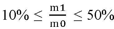
- the mass of the first positive electrode active material is less than the mass of the second positive electrode active material, and 10 % ⁇ m1 m0 ⁇ 50 % , wherein m1 represents the mass of the first positive electrode active material contained in the first positive electrode sheet, and m0 represents a total mass of the positive electrode active material contained in the first positive electrode sheet.
- the number of layers of positive active coating layer is greater than one, and an average single-side surface density of the positive active coating layer is 50 to 650 g/m 2 , and a specific surface resistance of the first positive electrode sheet is 0.0001 to 0.1500 ⁇ /mm 2 ⁇ g.
- the positive electrode active coating layer includes a first positive electrode coating layer and a second positive electrode active coating layer.
- a positive electrode active material contained in the first positive electrode active coating layer is the first positive electrode active material
- a positive electrode active material contained in the second positive electrode active coating layer is the second positive electrode active material.
- the composite cell provided in the present disclosure, by adjusting the proportion of the positive electrode active materials in the first positive electrode sheet, as well as the surface density and specific surface resistance of the first positive electrode sheet, it is beneficial to make the potential distribution of the first positive electrode sheet uniform, and alleviate lithium deposition phenomenon caused by excessive local current density of the electrode sheet, and at the same time, it is beneficial to improve the energy density of the electrode sheet. Furthermore, in the composite cell, a capacity balance state between different positive electrode sheets is basically achieved, so that current density uniformity of the composite cell is further ensured, and an impedance level of the electrode sheets is reduced.
- the first positive electrode sheet provided by the present disclosure has a stable structure, which can fully utilize the advantages of different positive electrode active materials, so as to effectively alleviate problems such as impedance and current imbalance occurring among different types of positive electrode active materials in the composite cell, thereby enabling the composite cell to have excellent energy density, high-low-temperature performance and cycle performance.
- a battery including the above composite cell is provided.
- Reference numerals in the drawings 100, battery; 10, battery housing; 1, composite cell; 1-1, second positive electrode sheet; 1-2; separator; 1-3, negative electrode sheet; 1-4, first positive electrode sheet; 1-41, first positive electrode active coating layer; 1-42, second positive electrode active coating layer; 2, composite cell; 2-1, second positive electrode sheet B; 2-2, separator; 2-3, negative electrode sheet; 2-4, second positive electrode sheet C.
- inventions of the present disclosure provide a composite cell 1.
- the composite cell 1 includes a plurality of positive electrode sheets, a plurality of separators 1-2, and a plurality of negative electrode sheet 1-3s 1-3.
- the plurality of positive electrode sheets and the plurality of negative electrode sheet 1-3s 1-3 are alternately stacked, with a separator 1-2 arranged between every two adjacent positive electrode sheet and negative electrode sheet 1-3.
- each positive electrode sheet satisfies a condition that a ratio of its capacity per unit area to a capacity per unit area of any other positive electrode sheet is 0.9 to 1.1.
- the positive electrode sheets include first positive electrode sheets 1-4, and positive electrode active materials contained in the first positive electrode sheet 1-4 include a first positive electrode active material and a second positive electrode active material. An energy density of the first positive electrode active material is greater than that of the second positive electrode active material.
- the mass of the first positive electrode active material is less than the mass of the second positive electrode active material, and 10 % ⁇ m1 m0 ⁇ 50 % , wherein m1 represents the mass of the first positive electrode active material contained in the first positive electrode sheet 1-4, and m0 represents a total mass of the positive electrode active material contained in the first positive electrode sheet 1-4.
- the number of layers of positive active coating layer is greater than one, and an average single-side surface density of the positive active coating layer is 50 to 650 g/m 2 , and a specific surface resistance of the first positive electrode sheet 1-4 is 0.0001 to 0.1500 ⁇ /mm 2 ⁇ g.
- the positive electrode active coating layer includes a first positive electrode active coating layer 1-41 and a second positive electrode active coating layer 1-42.
- a positive electrode active material contained in the first positive electrode active coating layer 1-41 is the first positive electrode active material
- a positive electrode active material contained in the second positive electrode active coating layer 1-42 is the second positive electrode active material.
- the composite cell 1 provided in the present disclosure, by adjusting the proportion of the positive electrode active materials in the first positive electrode sheet 1-4, as well as the surface density and specific surface resistance of the first positive electrode sheet 1-4, it is beneficial to make the potential distribution of the first positive electrode sheet 1-4 uniform, and alleviate lithium deposition phenomenon caused by excessive local current density of the electrode sheet, and at the same time, it is beneficial to improve the energy density of the electrode sheet. Furthermore, in the composite cell 1, a capacity balance state between different positive electrode sheets is basically achieved, so that current density uniformity of the composite cell is further ensured, and an impedance level of the electrode sheets is reduced.
- the first positive electrode sheet 1-4 provided by the present disclosure has a stable structure, which can fully utilize the advantages of different positive electrode active materials, so as to effectively alleviate problems such as impedance and current imbalance occurring among different types of positive electrode active materials in the composite cell, thereby enabling the composite cell to have excellent energy density, high-low-temperature performance and cycle performance.
- the mass proportion of the first positive electrode active material is too small, the precision of the coating process is limited, which easily leads to processing problems. In addition, during charging and discharging at a high rate, the non-uniform distribution of the lithium ion concentration and the potential is obvious, which easily leads to a lithium deposition phenomenon. If the mass proportion of the first positive electrode active material is too large, it is not conducive to structural stability of the first positive electrode sheet 1-4, and the cost is high.
- the surface density and specific surface resistance of the first positive electrode sheet 1-4 are too large, the electron transfer path is long and the transfer rate is slow, resulting in a decrease in the electronic conductivity of the electrode sheet. Moreover, during the lithium insertion and extraction process, the active material with a large volume effect easily peels off from the current collector, resulting in unstable structure of the electrode sheet. If the surface density and specific surface resistance of the first positive electrode sheet 1-4 are too low, the coating precision of the electrode sheet is limited, which tends to cause the processing problems, and is not conducive to the uniformity of the lithium ion extraction process, thereby causing a decrease in the energy density of the cell.
- the average surface density of the positive electrode active coating layer provided on the positive electrode sheet is Di
- the average gram capacity of the positive electrode active material contained in the positive electrode sheet is Ci
- the average first effect of the positive electrode active material is Ei
- the average mass proportion of the positive electrode active material is Wi
- the specific surface resistance of the positive electrode active coating layer equal to the surface resistance of the positive electrode active coating layer divided by the mass of the positive electrode active coating layer.
- the positive electrode sheets further include second positive electrode sheets 1-1, where an average single-side surface density of a positive electrode active coating layer provided on the second positive electrode sheet 1-1 is 65 to 700 g/m 2 , and a specific face resistance of the second positive electrode sheet 1-1 is 0.0002 to 0.2000 ⁇ /mm 2 ⁇ g.
- the second positive electrode sheet 1-1 with a specific surface density and specific surface resistance has an excellent mating effect with the first positive electrode sheet 1-4.
- the second positive electrode sheet 1-1 can play a synergistic advantage with the first positive electrode sheet 1-4 to ensure uniformity of current density among different positive electrode sheets.
- the average single-side surface density of the positive electrode active coating layer provided on the first positive electrode sheet 1-4 is 100 to 500 g/m 2
- the specific surface resistance of the first positive electrode sheet 1-4 is 0.0001 to 0.1200 ⁇ /mm 2 ⁇ g
- the average single-side surface density of the positive electrode active coating layer provided on the second positive electrode sheet 1-1 is 200 to 600 g/m 2
- the specific surface resistance of the second positive electrode sheet 1-1 is 0.0002 to 0.1600 ⁇ /mm 2 ⁇ g
- the first positive electrode active material is a ternary positive electrode material
- the second positive electrode active material includes at least one of lithium iron phosphate, lithium manganese iron phosphate, and lithium manganate.
- the positive electrode active coating layer formed by the first positive electrode active material and the positive electrode active coating layer formed by the second positive electrode active material are arranged in sequence
- the positive electrode active material contained in the second positive electrode sheet 1-1 includes one of lithium iron phosphate, lithium manganese iron phosphate, and lithium manganate.
- negative electrode active material contained in the negative electrode sheet 1-3 includes carbon negative electrode material and non-carbon negative electrode material.
- the carbon negative electrode material includes at least one of artificial graphite, natural graphite, hard carbon and soft carbon.
- the non-carbon negative electrode material includes at least one of silicon-based material, titanium-based material and tin-based material.
- embodiments of the present disclosure further provide a battery 100 containing the composite cell 1.
- the preparation method of the battery 100 provided by the present disclosure will be introduced bellow.
- This embodiment 1 provides a battery 100, which is prepared as follows.
- Positive electrode slurry A is prepared by evenly mixing lithium iron phosphate, binder (such as Polyvinylidene Fluoride (PVDF)), and conductive agent (such as acetylene black) according to a mass ratio of 98:1:1.
- the positive electrode slurry A is then coated on both sides of a positive electrode current collector, and dried to form a positive electrode active coating layer A.
- a second positive electrode sheet A 1-1 with the positive electrode active coating layer A is prepared.
- An average single-side surface density S A of the positive electrode active coating layer A is 210 g/m 2 .
- a specific surface resistance R A of the second positive electrode sheet A 1-1 is 0.1230 ⁇ /mm 2 ⁇ g.
- Positive electrode slurry A is prepared by evenly mixing lithium iron phosphate, binder (such as PVDF), and conductive agent (such as acetylene black) according to a mass ratio of 98:1:1.
- Positive electrode slurry C is prepared by evenly mixing ternary positive electrode material, binder (such as PVDF), and conductive agent (such as acetylene black) according to a mass ratio of 90:5:5. Then, the positive electrode slurry C is coated on both sides of a positive electrode current collector, and then dried to form a first positive electrode active coating layer 1-41. Next, the positive electrode slurry A is coated on the surface of the first positive electrode active coating layer 1-41, and then dried to form a second positive electrode active coating layer 1-42.
- a first positive electrode sheet D1 1-4 is prepared, and the first positive electrode active coating layer 1-41 and the second positive electrode active coating layer 1-42 together constitute a composite positive electrode active coating layer provided on the first positive electrode sheet D1 1-4.
- an average single-side surface density S D1 of the composite positive electrode active coating layer is 165 g/m 2 .
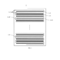
- FIG. 1 A structural schematic diagram of a composite cell 1 is shown in FIG. 1 .
- the composite cell 1 is formed by stacking a separator 1-2, a negative electrode sheet 1-3, a separator 1-2, the second positive electrode sheet A 1-1, a separator 1-2, a negative electrode sheet 1-3, a separator 1-2, the first positive electrode sheet D1 1-4, a separator 1-2, and a negative electrode sheet 1-3 in sequence (the number of the second positive electrode sheets A 1-1 is 6, and the number of the first positive electrode sheets D1 1-4 is 44).
- the composite cell 1 is placed in a battery housing 10, and then processing such as welding of electrode tabs and baking is performed on the battery housing 10. After the moisture content is tested to be qualified, an appropriate amount of electrolyte is injected into the battery housing 10, and then the battery housing 10 is encapsulated by aging, formation, and air-extracting, to prepare a battery 100.
- FIG. 1 A structural schematic diagram of the composite cell 1 prepared in this embodiment is shown in FIG. 1 .
- This embodiment 2 provides a battery 100, which is prepared as follows.
- Positive electrode slurry B is prepared by evenly mixing lithium manganese iron phosphate, binder (such as PVDF), and conductive agent (such as acetylene black) according to a mass ratio of 98:1:1.
- the positive electrode slurry B is then coated on both sides of a positive electrode current collector, and dried to form a positive electrode active coating layer B.
- a second positive electrode sheet B 1-1 with the positive electrode active coating layer B is prepared.
- An average single-side surface density S B of the positive electrode active coating layer B is 175 g/m 2 .
- a specific surface resistance R B of the second positive electrode sheet B 1-1 is 0.1230 ⁇ /mm 2 ⁇ g.
- Positive electrode slurry B is prepared by evenly mixing lithium manganese iron phosphate, binder (such as PVDF), and conductive agent (such as acetylene black) according to a mass ratio of 98:1:1.
- Positive electrode slurry C is prepared by evenly mixing ternary positive electrode material, binder (such as PVDF), and conductive agent (such as acetylene black) according to a mass ratio of 90:5:5. Then, the positive electrode slurry C is coated on both sides of a positive electrode current collector, and then dried to form a first positive electrode active coating layer 1-41. Next, the positive electrode slurry B is coated on the surface of the first positive electrode active coating layer 1-41, and then dried to form a second positive electrode active coating layer 1-42.
- a first positive electrode sheet D2 1-4 is prepared, and the first positive electrode active coating layer 1-41 and the second positive electrode active coating layers 1-42 together constitute a composite positive electrode active coating layer provided on the first positive electrode sheet D2 1-4.
- an average single-side surface density S D2 of the composite positive electrode active coating layer is 160 g/m 2 .
- FIG. 1 A structural schematic diagram of a composite cell 1 is shown in FIG. 1 .
- the composite cell 1 is formed by stacking a separator 1-2, a negative electrode sheet 1-3, a separator 1-2, the second positive electrode sheet B 1-1, a separator 1-2, a negative electrode sheet 1-3, a separator 1-2, the first positive electrode sheet D2 1-4, a separator 1-2, and a negative electrode sheet 1-3 in sequence (the number of the second positive electrode sheets B 1-1 is 6, and the number of the first positive electrode sheets D2 1-4 is 44).
- the composite cell 1 is placed in a battery housing 10, and then processing such as welding electrode tabs and baking is performed on the battery housing 10. After the moisture content is tested to be qualified, an appropriate amount of electrolyte is injected into the battery housing 10, and then the battery housing 10 is encapsulated by aging, formation, and air-extracting, to prepare a battery 100.
- FIG. 1 A structural schematic diagram of the composite cell 1 prepared in this embodiment is shown in FIG. 1 .
- This embodiment 3 provides a battery 100, which is prepared as follows.
- the preparation method of the second positive electrode sheet A 1-1 please refers to the preparation of the second positive electrode sheet A 1-1 in embodiment 1.
- the preparation method of the first positive electrode sheet D2 1-4 please refers to the preparation of the first positive electrode sheet D2 1-4 in embodiment 2.
- FIG. 1 A structural schematic diagram of a composite cell 1 is shown in FIG. 1 .
- the composite cell 1 is formed by stacking a separator 1-2, a negative electrode sheet 1-3, a separator 1-2, the second positive electrode sheet A 1-1, a separator 1-2, a negative electrode sheet 1-3, a separator 1-2, the first positive electrode sheet D2 1-4, a separator 1-2, and a negative electrode sheet 1-3 in sequence (the number of the second positive electrode sheets A 1-1 is 6, and the number of the first positive electrode sheets D2 1-4 is 44).
- the composite cell 1 is placed in a battery housing 10, and then processing such as welding electrode tabs and baking is performed on the battery housing 10. After the moisture content is tested to be qualified, an appropriate amount of electrolyte is injected into the battery housing 10, and then the battery housing 10 is encapsulated by aging, formation, and air-extracting, to prepare a battery 100.
- FIG. 1 A structural schematic diagram of the composite cell 1 prepared in this embodiment is shown in FIG. 1 .
- This embodiment 4 provides a battery 100, which is prepared as follows.
- the preparation method of the second positive electrode sheet A 1-1 please refers to the preparation of the second positive electrode sheet A 1-1 in embodiment 1.
- Positive electrode slurry C is prepared by evenly mixing ternary positive electrode material, binder (such as PVDF), and conductive agent (such as acetylene black) according to a mass ratio of 90:5:5.
- Positive electrode slurry D is prepared by evenly mixing lithium manganate, binder (such as PVDF), and conductive agent (such as acetylene black) according to a mass ratio of 94:3:3. Then, the positive electrode slurry C is coated on both sides of a positive electrode current collector, and then dried to form a first positive electrode active coating layer 1-41. Next, the positive electrode slurry D is coated on the surface of the first positive electrode active coating layer 1-41, and then dried to form a second positive electrode active coating layer 1-42.
- a first positive electrode sheet D3 1-4 is prepared, and the first positive electrode active coating layers 1-41 and the second positive electrode active coating layers 1-42 together constitute a composite positive electrode active coating layer provided on the first positive electrode sheet D3 1-4.
- an average single-side surface density S D3 of the composite positive electrode active coating layer is 175 g/m 2 .
- FIG. 1 A structural schematic diagram of a composite cell 1 is shown in FIG. 1 .
- the composite cell 1 is formed by stacking a separator 1-2, a negative electrode sheet 1-3, a separator 1-2, the second positive electrode sheet A 1-1, a separator 1-2, a negative electrode sheet 1-3, a separator 1-2, the first positive electrode sheet D3 1-4, a separator 1-2, and a negative electrode sheet 1-3 in sequence (the number of the second positive electrode sheets A 1-1 is 6, and the number of the first positive electrode sheets D3 1-4 is 44).
- the composite cell 1 is placed in a battery housing 10, and then processing such as welding electrode tabs and baking is performed on the battery housing 10. After the moisture content is tested to be qualified, an appropriate amount of electrolyte is injected into the battery housing 10, and then the battery housing 10 is encapsulated by aging, formation, and air-extracting, to prepare a battery 100.
- FIG. 1 A structural schematic diagram of the composite cell 1 prepared in this embodiment is shown in FIG. 1 .
- a battery 100 is prepared with reference to embodiment 1.
- FIG. 1 A structural schematic diagram of the composite cell 1 prepared in this embodiment 5 is shown in FIG. 1 .
- a battery 100 is prepared with reference to embodiment 1.
- FIG. 1 A structural schematic diagram of the composite cell 1 prepared in this embodiment 6 is shown in FIG. 1 .
- a battery 100 is prepared with reference to embodiment 1.
- FIG. 1 A structural schematic diagram of the composite cell 1 prepared in this embodiment 7 is shown in FIG. 1 .
- a battery 100 is prepared with reference to embodiment 1.
- FIG. 1 A structural schematic diagram of the composite cell 1 prepared in this embodiment 8 is shown in FIG. 1 .
- a battery 100 is prepared with reference to embodiment 1.
- the difference between this embodiment 9 and embodiment 1 is that: in the second positive electrode sheet A 1-1, the average single-side surface density S A of the positive electrode active coating layer A is 50 g/m 2 , and the specific surface resistance R A is 0.0001 ⁇ /mm 2 ⁇ g. Except for these differences, the materials and process operations used in this embodiment 9 are strictly consistent with those used in embodiment 1.
- FIG. 1 A structural schematic diagram of the composite cell 1 prepared in this embodiment 9 is shown in FIG. 1 .
- a battery 100 is prepared with reference to embodiment 1.
- the difference between this embodiment 10 and embodiment 1 is that: in the second positive electrode sheet A 1-1, the average single-side surface density S A of the positive electrode active coating layer A is 65 g/m 2 , and the specific surface resistance R A is 0.0002 ⁇ /mm 2 ⁇ g. Except for these differences, the materials and process operations used in this embodiment 10 are strictly consistent with those used in embodiment 1.
- FIG. 1 A structural schematic diagram of the composite cell 1 prepared in this embodiment 10 is shown in FIG. 1 .
- a battery 100 is prepared with reference to embodiment 1.
- the difference between this embodiment 11 and embodiment 1 is that: in the second positive electrode sheet A 1-1, the average single-side surface density S A of the positive electrode active coating layer A is 700 g/m 2 , and the specific surface resistance R A is 0.2 ⁇ /mm 2 ⁇ g. Except for these differences, the materials and process operations used in this embodiment 11 are strictly consistent with those used in embodiment 1.
- FIG. 1 A structural schematic diagram of the composite cell 1 prepared in this embodiment 11 is shown in FIG. 1 .
- a battery 100 is prepared with reference to embodiment 1.
- the difference between this embodiment 12 and embodiment 1 is that: in the second positive electrode sheet A 1-1, the average single-side surface density S A of the positive electrode active coating layer A is 750 g/m 2 , and the specific surface resistance R A is 0.25 ⁇ /mm 2 ⁇ g. Except for these differences, the materials and process operations used in this embodiment 12 are strictly consistent with those used in embodiment 1.
- FIG. 1 A structural schematic diagram of the composite cell 1 prepared in this embodiment 12 is shown in FIG. 1 .
- a battery 100 is prepared with reference to embodiment 1.
- the difference between this embodiment 13 and embodiment 1 is that: in the first positive electrode sheet D1 1-4, the average single-side surface density S D1 of the composite positive electrode active coating layer is 650 g/m 2 , and the specific surface resistance R D1 is 0.0001 ⁇ /mm 2 ⁇ g. Except for these differences, the materials and process operations used in this embodiment 13 are strictly consistent with those used in embodiment 1.
- FIG. 1 A structural schematic diagram of the composite cell 1 prepared in this embodiment 13 is shown in FIG. 1 .
- a battery 100 is prepared with reference to embodiment 1.
- the difference between this embodiment 14 and embodiment 1 is that: in the first positive electrode sheet D1 1-4, the average single-side surface density S D1 of the composite positive electrode active coating layer is 50 g/m 2 , and the specific surface resistance R D1 is 0.0500 ⁇ /mm 2 ⁇ g. Except for these differences, the materials and process operations used in this embodiment 14 are strictly consistent with those used in embodiment 1.
- FIG. 1 A structural schematic diagram of the composite cell 1 prepared in this embodiment 14 is shown in FIG. 1 .
- This comparative example 1 provides a battery 100, which is prepared as follows.
- Positive electrode slurry B is prepared by evenly mixing lithium manganese iron phosphate, binder (such as PVDF), and conductive agent (such as acetylene black) according to a mass ratio of 98:1:1.
- the positive electrode slurry B is then coated on both sides of a positive electrode current collector, and dried to form a positive electrode active coating layer B.
- a second positive electrode sheet B 2-1 with the positive electrode active coating layer B is prepared.
- An average single-side surface density S B of the positive electrode active coating layer B is 175 g/m 2
- a specific surface resistance R B of the second positive electrode sheet B 2-1 is 0.1200 ⁇ /mm 2 ⁇ g.
- Positive electrode slurry C is prepared by evenly mixing ternary positive electrode material, binder (such as PVDF), and conductive agent (such as acetylene black) according to a mass ratio of 90:5:5. Then, the positive electrode slurry C is coated on both sides of a positive electrode current collector, and then dried to form a positive electrode active coating layer C. In this way, a second positive electrode sheet C 2-4 with the positive electrode active coating layer C is prepared.
- An average single-side surface density Sc of the positive electrode active coating layer C is 150 g/m 2
- a specific surface resistance R C of the second positive electrode sheet C 2-4 is 0.1250 ⁇ /mm 2 ⁇ g.
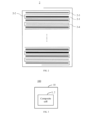
- FIG. 2 A structural schematic diagram of a composite cell 2 is shown in FIG. 2 .
- the composite cell 2 is formed by stacking a separator 2-2, a negative electrode sheet 2-3, a separator 2-2, the second positive electrode sheet B 2-1, a separator 2-2, a negative electrode sheet 2-3, a separator 2-2, the second positive electrode sheet C 2-4, a separator 2-2, and a negative electrode sheet 2-3 in sequence (the number of the second positive electrode sheets B 2-1 is 44, and the number of the second positive electrode sheet C 2-4 is 6).
- the composite cell 2 is placed in a battery housing 10, and then processing such as welding of electrode tabs and baking is performed on the battery housing 10. After the moisture content is tested to be qualified, an appropriate amount of electrolyte is injected into the battery housing 10, and then the battery housing 10 is encapsulated by aging, formation, and air-extracting, to prepare a battery 100.
- FIG. 2 A structural schematic diagram of the composite cell 2 prepared in this comparative example is shown in FIG. 2 .
- a battery 100 is prepared with reference to embodiment 1.
- FIG. 1 A structural schematic diagram of the composite cell 1 prepared in this comparative example 2 is shown in FIG. 1 .
- a battery 100 is prepared with reference to embodiment 1.
- the difference between this comparative example 3 and embodiment 1 is that: in the first positive electrode sheets D1 1-4, the average single-side surface density S D1 of the composite positive electrode active coating layer is 30 g/m 2 , and the specific surface resistance R D1 is 0.00007 ⁇ /mm 2 ⁇ g. Except for these differences, the materials and process operations used in this comparative example 3 are strictly consistent with those used in embodiment 1.
- FIG. 1 A structural schematic diagram of the composite cell 1 prepared in this comparative example 3 is shown in FIG. 1 .
- a battery 100 is prepared with reference to embodiment 1.
- the difference between this comparative example 4 and embodiment 1 is that: in the first positive electrode sheets D1 1-4, the average single-side surface density S D1 of the composite positive electrode active coating layer is 700 g/m 2 , and the specific surface resistance R D1 is 0.20 ⁇ /mm 2 ⁇ g. Except for these differences, the materials and process operations used in this comparative example 4 are strictly consistent with those used in embodiment 1.
- FIG. 1 A structural schematic diagram of the composite cell 1 prepared in this comparative example 4 is shown in FIG. 1 .
- the batteries prepared in embodiments 1 to 14 and comparative examples 1 to 4 were used as the test objects of this test example.
- Table 2 shows the test results of the relevant performance of the batteries prepared in embodiments 1 to 14 and comparative examples 1 to 4.
- the battery prepared in embodiment 1 has a low impedance level and excellent energy density and cycle performance.
- the composite cell prepared in comparative example 1 is provided with only second positive electrode sheets, the cycle performance of the battery thus obtained was significantly lower than that of the battery prepared in embodiment 1. It is thus indicated that, compared to comparative example 1, the battery provided in embodiment 1 is provided with first positive electrode sheets, which have stable structures and can fully utilize the advantages of different positive electrode active materials, so as to effectively alleviate problems such as impedance and current imbalance occurring among different types of positive electrode active materials in the composite cell, thereby improving the energy density and cycle performance of the battery.
- the battery prepared in embodiment 1 has a low impedance level and excellent energy density and cycle performance.
- the mass proportion of the first positive electrode active material exceeds the range of 10% to 50%, and the cycle performance of the battery thus obtained was significantly lower than that of the battery prepared in embodiment 1.
- the battery provided in embodiment 1 by reasonably setting the proportion of the first positive electrode active material in the first positive electrode sheet, is beneficial to make the potential distribution of the first positive electrode sheet uniform, and alleviate the lithium deposition phenomenon caused by excessive local current density of the electrode sheet, thereby improving the energy density and cycle performance of the battery.
- the battery prepared in embodiment 1 has a low impedance level and excellent energy density and cycle performance.
- the composite positive electrode active coating layer provided on the first positive electrode sheet prepared in comparative example 3 has an average single-side surface density S D1 less than 50 g/m 2 , and the specific surface resistance R D1 is less than 0.0001 ⁇ /mm 2 ⁇ g; the composite positive electrode active coating layer provided on the first positive electrode sheet prepared in comparative example 4 has an average single-side surface density S D1 greater than 650 g/m 2 , and the specific surface resistance R D1 was greater than 0.1500 ⁇ /mm 2 ⁇ g, and the cycle performance of the battery thus obtained was significantly lower than that of the battery prepared in embodiment 1.
- the battery provided in embodiment 1 by reasonably setting the surface density and the specific surface resistance of the composite positive electrode active coating layer in the first positive electrode sheet, is beneficial to make the potential distribution of the first positive electrode sheet uniform, and alleviate the lithium deposition phenomenon caused by excessive local current density of the electrode sheet, thereby improving the energy density and cycle performance of the battery.
- the composite cell provided in embodiments 1, 6 to 7, by reasonably setting the content of the first positive electrode active material in the composite cell is beneficial for improving the matching effect between different positive electrode active materials, achieving the overall current density uniformity of the composite cell, allowing the positive electrode active materials with different energy density to exert their synergistic advantages, thereby improving the energy density and cycle performance of the battery.
- the positive electrode active coating layer provided on the second positive electrode sheet in embodiment 9 has an average single-side surface density S A less than 65 g/m 2 , and the specific surface resistance R A was less than 0.0002 ⁇ /mm 2 ⁇ g; the positive electrode active coating layer provided on the second positive electrode sheet in embodiment 12 has an average single-side surface density S A greater than 700 g/m 2 , and the specific areal resistance R A was greater than 0.2000 ⁇ /mm 2 ⁇ g, and the battery thus obtained had cycle performance lower than that of the battery prepared in embodiment 1.
- the composite cell provided in embodiments 1, 10 and 11 is designed by reasonably setting the surface density and specific surface resistance of the second positive electrode sheet, so that the second positive electrode sheet with a specific surface density and specific surface resistance has an excellent matching effect with the first positive electrode sheet, and can play a synergistic advantage with the first positive electrode sheet to ensure the uniformity of the current density among different positive electrode sheets, and avoid the phenomena such as unstable electrode sheet structure, lithium deposition, polarization, caused by poor matching effect of the electrode sheets, thereby improving the energy density and cycle performance of the battery.
Landscapes
- Chemical & Material Sciences (AREA)
- Chemical Kinetics & Catalysis (AREA)
- Electrochemistry (AREA)
- General Chemical & Material Sciences (AREA)
- Engineering & Computer Science (AREA)
- Manufacturing & Machinery (AREA)
- Composite Materials (AREA)
- Materials Engineering (AREA)
- Inorganic Chemistry (AREA)
- Crystallography & Structural Chemistry (AREA)
- Battery Electrode And Active Subsutance (AREA)
- Secondary Cells (AREA)
Abstract
A composite cell (1) and a battery containing the composite cell are provided. The composite cell includes positive electrode sheets. Each positive electrode sheet satisfies a condition that a ratio of its capacity per unit area to a capacity per unit area of any other positive electrode sheet is 0.9 to 1.1. The positive electrode sheets include first positive electrode sheets (1-4), and positive electrode active materials contained in the first positive electrode sheet include a first positive electrode active material and a second positive electrode active material. An energy density of the first positive electrode active material is greater than that of the second positive electrode active material. On each of the first positive electrode sheets, 
50%, an average single-side surface density of the positive active coating layer is 50 to 650 g/m2, and a specific surface resistance is 0.0001 to 0.1500 Ω/mm2·g.
Description
- The present disclosure relates to the technology field of batteries, and in particular, to a composite cell and a battery containing the same.
- Materials of positive electrodes of mainstream lithium-ion battery mainly include oxide-based positive electrode active material systems and phosphate-based positive electrode active material systems. The oxide-based positive electrode active materials have high energy density but poor structural stability, while the phosphate-based positive electrode active materials have low energy density but long cycle life and obvious advantages of cost and safety. How to give full play to the complementary advantages of different materials has always been a difficult problem in the industry. At present, in the industry, positive electrode slurry formed by mixing different types of positive electrode active materials in a blending manner is generally coated directly on surfaces of a current collector to prepare a positive electrode sheet. However, differences in particle sizes and surface energies of different types of positive electrode active materials lead to agglomeration of the mixed slurry. The above-mentioned problems can be avoided to a certain extent by means of a multi-layer coating method. However, when the proportions of different types of positive electrode active materials differ greatly, the coating surface density of the material with a smaller proportion is too small, and the coating process cannot be realized.
- Thus, how to integrate different types of positive electrode sheets in the same cell and give full play to the synergistic advantages of different types of positive electrode active materials is a technical problem to be solved urgently by one of ordinary skill in the art in research.
- In a first aspect of the present disclosure, a composite cell is provided. The composite cell includes positive electrode sheets. The number of the positive electrode sheets is greater than one. Each positive electrode sheet satisfies a condition that a ratio of its capacity per unit area to a capacity per unit area of any other positive electrode sheet is 0.9 to 1.1. The positive electrode sheets include first positive electrode sheets, and positive electrode active materials contained in the first positive electrode sheet include a first positive electrode active material and a second positive electrode active material. An energy density of the first positive electrode active material is greater than that of the second positive electrode active material. On each of the first positive electrode sheets, the mass of the first positive electrode active material is less than the mass of the second positive electrode active material, and
- In the composite cell provided in the present disclosure, by adjusting the proportion of the positive electrode active materials in the first positive electrode sheet, as well as the surface density and specific surface resistance of the first positive electrode sheet, it is beneficial to make the potential distribution of the first positive electrode sheet uniform, and alleviate lithium deposition phenomenon caused by excessive local current density of the electrode sheet, and at the same time, it is beneficial to improve the energy density of the electrode sheet. Furthermore, in the composite cell, a capacity balance state between different positive electrode sheets is basically achieved, so that current density uniformity of the composite cell is further ensured, and an impedance level of the electrode sheets is reduced. Based on this, the first positive electrode sheet provided by the present disclosure has a stable structure, which can fully utilize the advantages of different positive electrode active materials, so as to effectively alleviate problems such as impedance and current imbalance occurring among different types of positive electrode active materials in the composite cell, thereby enabling the composite cell to have excellent energy density, high-low-temperature performance and cycle performance.
- In a second aspect of the present disclosure, a battery including the above composite cell is provided.
-
-
FIG. 1 is a structural schematic diagram of a composite cell in embodiments 1 to 14 and comparative examples 2 to 4. -
FIG. 2 is a structural schematic diagram of a composite cell in a comparative example 1. -
FIG. 3 is a schematic diagram of a battery according to some embodiments. - Reference numerals in the drawings: 100, battery; 10, battery housing; 1, composite cell; 1-1, second positive electrode sheet; 1-2; separator; 1-3, negative electrode sheet; 1-4, first positive electrode sheet; 1-41, first positive electrode active coating layer; 1-42, second positive electrode active coating layer; 2, composite cell; 2-1, second positive electrode sheet B; 2-2, separator; 2-3, negative electrode sheet; 2-4, second positive electrode sheet C.
- Referring to
FIG. 1 , embodiments of the present disclosure provide a composite cell 1. The composite cell 1 includes a plurality of positive electrode sheets, a plurality of separators 1-2, and a plurality of negative electrode sheet 1-3s 1-3. The plurality of positive electrode sheets and the plurality of negative electrode sheet 1-3s 1-3 are alternately stacked, with a separator 1-2 arranged between every two adjacent positive electrode sheet and negative electrode sheet 1-3. - In these embodiments of the present disclosure, each positive electrode sheet satisfies a condition that a ratio of its capacity per unit area to a capacity per unit area of any other positive electrode sheet is 0.9 to 1.1. The positive electrode sheets include first positive electrode sheets 1-4, and positive electrode active materials contained in the first positive electrode sheet 1-4 include a first positive electrode active material and a second positive electrode active material. An energy density of the first positive electrode active material is greater than that of the second positive electrode active material. On each of the first positive electrode sheets 1-4, the mass of the first positive electrode active material is less than the mass of the second positive electrode active material, and

- In the composite cell 1 provided in the present disclosure, by adjusting the proportion of the positive electrode active materials in the first positive electrode sheet 1-4, as well as the surface density and specific surface resistance of the first positive electrode sheet 1-4, it is beneficial to make the potential distribution of the first positive electrode sheet 1-4 uniform, and alleviate lithium deposition phenomenon caused by excessive local current density of the electrode sheet, and at the same time, it is beneficial to improve the energy density of the electrode sheet. Furthermore, in the composite cell 1, a capacity balance state between different positive electrode sheets is basically achieved, so that current density uniformity of the composite cell is further ensured, and an impedance level of the electrode sheets is reduced. Based on this, the first positive electrode sheet 1-4 provided by the present disclosure has a stable structure, which can fully utilize the advantages of different positive electrode active materials, so as to effectively alleviate problems such as impedance and current imbalance occurring among different types of positive electrode active materials in the composite cell, thereby enabling the composite cell to have excellent energy density, high-low-temperature performance and cycle performance.
- If the mass proportion of the first positive electrode active material is too small, the precision of the coating process is limited, which easily leads to processing problems. In addition, during charging and discharging at a high rate, the non-uniform distribution of the lithium ion concentration and the potential is obvious, which easily leads to a lithium deposition phenomenon. If the mass proportion of the first positive electrode active material is too large, it is not conducive to structural stability of the first positive electrode sheet 1-4, and the cost is high.
- If the surface density and specific surface resistance of the first positive electrode sheet 1-4 are too large, the electron transfer path is long and the transfer rate is slow, resulting in a decrease in the electronic conductivity of the electrode sheet. Moreover, during the lithium insertion and extraction process, the active material with a large volume effect easily peels off from the current collector, resulting in unstable structure of the electrode sheet. If the surface density and specific surface resistance of the first positive electrode sheet 1-4 are too low, the coating precision of the electrode sheet is limited, which tends to cause the processing problems, and is not conducive to the uniformity of the lithium ion extraction process, thereby causing a decrease in the energy density of the cell.
- Specifically, the average surface density of the positive electrode active coating layer provided on the positive electrode sheet is Di, the average gram capacity of the positive electrode active material contained in the positive electrode sheet is Ci, the average first effect of the positive electrode active material is Ei, the average mass proportion of the positive electrode active material is Wi, and the capacity per unit area thereof is: Qi = Di * Ci * Wi/Ei.
- Specifically, the specific surface resistance of the positive electrode active coating layer equal to the surface resistance of the positive electrode active coating layer divided by the mass of the positive electrode active coating layer.
- In these embodiments, the positive electrode sheets further include second positive electrode sheets 1-1, where an average single-side surface density of a positive electrode active coating layer provided on the second positive electrode sheet 1-1 is 65 to 700 g/m2, and a specific face resistance of the second positive electrode sheet 1-1 is 0.0002 to 0.2000 Ω/mm2·g. The second positive electrode sheet 1-1 with a specific surface density and specific surface resistance has an excellent mating effect with the first positive electrode sheet 1-4. The second positive electrode sheet 1-1 can play a synergistic advantage with the first positive electrode sheet 1-4 to ensure uniformity of current density among different positive electrode sheets. In this way, phenomena such as unstable electrode sheet structure, lithium deposition, and polarization caused by poor matching effect of the electrode sheets are avoided, so that the energy density, high-low-temperature performance, and cycle performance of the composite cell 1 provided in the present disclosure are improved as a whole.
- In some embodiemnts,

- In some embodiemnts, the average single-side surface density of the positive electrode active coating layer provided on the first positive electrode sheet 1-4 is 100 to 500 g/m2, and the specific surface resistance of the first positive electrode sheet 1-4 is 0.0001 to 0.1200 Ω/mm2·g
- In some embodiemnts, the average single-side surface density of the positive electrode active coating layer provided on the second positive electrode sheet 1-1 is 200 to 600 g/m2, and the specific surface resistance of the second positive electrode sheet 1-1 is 0.0002 to 0.1600 Ω/mm2·g
- In some embodiemnts, the composite cell satisfies a condition that:

- In some embodiemnts, the first positive electrode active material is a ternary positive electrode material, and the second positive electrode active material includes at least one of lithium iron phosphate, lithium manganese iron phosphate, and lithium manganate.
- In some embodiemnts, on a same side of a current collector of the first positive electrode sheet 1-4, in a direction away from a surface of the current collector, the positive electrode active coating layer formed by the first positive electrode active material and the positive electrode active coating layer formed by the second positive electrode active material are arranged in sequence
- In some embodiemnts, the positive electrode active material contained in the second positive electrode sheet 1-1 includes one of lithium iron phosphate, lithium manganese iron phosphate, and lithium manganate.
- In some embodiemnts, negative electrode active material contained in the negative electrode sheet 1-3 includes carbon negative electrode material and non-carbon negative electrode material. The carbon negative electrode material includes at least one of artificial graphite, natural graphite, hard carbon and soft carbon. The non-carbon negative electrode material includes at least one of silicon-based material, titanium-based material and tin-based material.
- Referring to
FIG. 3 , embodiments of the present disclosure further provide abattery 100 containing the composite cell 1. The preparation method of thebattery 100 provided by the present disclosure will be introduced bellow. - This embodiment 1 provides a
battery 100, which is prepared as follows. - Positive electrode slurry A is prepared by evenly mixing lithium iron phosphate, binder (such as Polyvinylidene Fluoride (PVDF)), and conductive agent (such as acetylene black) according to a mass ratio of 98:1:1. The positive electrode slurry A is then coated on both sides of a positive electrode current collector, and dried to form a positive electrode active coating layer A. In this way, a second positive electrode sheet A 1-1 with the positive electrode active coating layer A is prepared. An average single-side surface density SA of the positive electrode active coating layer A is 210 g/m2. A specific surface resistance RA of the second positive electrode sheet A 1-1 is 0.1230 Ω/mm2·g.
- Positive electrode slurry A is prepared by evenly mixing lithium iron phosphate, binder (such as PVDF), and conductive agent (such as acetylene black) according to a mass ratio of 98:1:1. Positive electrode slurry C is prepared by evenly mixing ternary positive electrode material, binder (such as PVDF), and conductive agent (such as acetylene black) according to a mass ratio of 90:5:5. Then, the positive electrode slurry C is coated on both sides of a positive electrode current collector, and then dried to form a first positive electrode active coating layer 1-41. Next, the positive electrode slurry A is coated on the surface of the first positive electrode active coating layer 1-41, and then dried to form a second positive electrode active coating layer 1-42. In this way, a first positive electrode sheet D1 1-4 is prepared, and the first positive electrode active coating layer 1-41 and the second positive electrode active coating layer 1-42 together constitute a composite positive electrode active coating layer provided on the first positive electrode sheet D1 1-4. In the first positive electrode sheet D1 1-4, an average single-side surface density SD1 of the composite positive electrode active coating layer is 165 g/m2. A specific surface resistance RD1 of the first positive electrode sheet D1 1-4 is 0.0500 Ω/mm2·g, and

- A structural schematic diagram of a composite cell 1 is shown in
FIG. 1 . The composite cell 1 is formed by stacking a separator 1-2, a negative electrode sheet 1-3, a separator 1-2, the second positive electrode sheet A 1-1, a separator 1-2, a negative electrode sheet 1-3, a separator 1-2, the first positive electrode sheet D1 1-4, a separator 1-2, and a negative electrode sheet 1-3 in sequence (the number of the second positive electrode sheets A 1-1 is 6, and the number of the first positive electrode sheets D1 1-4 is 44). The composite cell 1 satisfies:

- As shown in
FIG. 3 , the composite cell 1 is placed in abattery housing 10, and then processing such as welding of electrode tabs and baking is performed on thebattery housing 10. After the moisture content is tested to be qualified, an appropriate amount of electrolyte is injected into thebattery housing 10, and then thebattery housing 10 is encapsulated by aging, formation, and air-extracting, to prepare abattery 100. - A structural schematic diagram of the composite cell 1 prepared in this embodiment is shown in
FIG. 1 . - This
embodiment 2 provides abattery 100, which is prepared as follows. - Positive electrode slurry B is prepared by evenly mixing lithium manganese iron phosphate, binder (such as PVDF), and conductive agent (such as acetylene black) according to a mass ratio of 98:1:1. The positive electrode slurry B is then coated on both sides of a positive electrode current collector, and dried to form a positive electrode active coating layer B. In this way, a second positive electrode sheet B 1-1 with the positive electrode active coating layer B is prepared. An average single-side surface density SB of the positive electrode active coating layer B is 175 g/m2. A specific surface resistance RB of the second positive electrode sheet B 1-1 is 0.1230 Ω/mm2·g.
- Positive electrode slurry B is prepared by evenly mixing lithium manganese iron phosphate, binder (such as PVDF), and conductive agent (such as acetylene black) according to a mass ratio of 98:1:1. Positive electrode slurry C is prepared by evenly mixing ternary positive electrode material, binder (such as PVDF), and conductive agent (such as acetylene black) according to a mass ratio of 90:5:5. Then, the positive electrode slurry C is coated on both sides of a positive electrode current collector, and then dried to form a first positive electrode active coating layer 1-41. Next, the positive electrode slurry B is coated on the surface of the first positive electrode active coating layer 1-41, and then dried to form a second positive electrode active coating layer 1-42. In this way, a first positive electrode sheet D2 1-4 is prepared, and the first positive electrode active coating layer 1-41 and the second positive electrode active coating layers 1-42 together constitute a composite positive electrode active coating layer provided on the first positive electrode sheet D2 1-4. In the first positive electrode sheet D2 1-4, an average single-side surface density SD2 of the composite positive electrode active coating layer is 160 g/m2. A specific surface resistance RD2 of the first positive electrode sheet D2 1-4 is 0.0800 Ω/mm2·g, and

- A structural schematic diagram of a composite cell 1 is shown in
FIG. 1 . The composite cell 1 is formed by stacking a separator 1-2, a negative electrode sheet 1-3, a separator 1-2, the second positive electrode sheet B 1-1, a separator 1-2, a negative electrode sheet 1-3, a separator 1-2, the first positive electrode sheet D2 1-4, a separator 1-2, and a negative electrode sheet 1-3 in sequence (the number of the second positive electrode sheets B 1-1 is 6, and the number of the first positive electrode sheets D2 1-4 is 44). The composite cell 1 satisfies:

- As shown in
FIG. 3 , the composite cell 1 is placed in abattery housing 10, and then processing such as welding electrode tabs and baking is performed on thebattery housing 10. After the moisture content is tested to be qualified, an appropriate amount of electrolyte is injected into thebattery housing 10, and then thebattery housing 10 is encapsulated by aging, formation, and air-extracting, to prepare abattery 100. - A structural schematic diagram of the composite cell 1 prepared in this embodiment is shown in
FIG. 1 . - This embodiment 3 provides a
battery 100, which is prepared as follows. - The preparation method of the second positive electrode sheet A 1-1 please refers to the preparation of the second positive electrode sheet A 1-1 in embodiment 1.
- The preparation method of the first positive electrode sheet D2 1-4 please refers to the preparation of the first positive electrode sheet D2 1-4 in
embodiment 2. - A structural schematic diagram of a composite cell 1 is shown in
FIG. 1 . The composite cell 1 is formed by stacking a separator 1-2, a negative electrode sheet 1-3, a separator 1-2, the second positive electrode sheet A 1-1, a separator 1-2, a negative electrode sheet 1-3, a separator 1-2, the first positive electrode sheet D2 1-4, a separator 1-2, and a negative electrode sheet 1-3 in sequence (the number of the second positive electrode sheets A 1-1 is 6, and the number of the first positive electrode sheets D2 1-4 is 44). The composite cell 1 satisfies:

- As shown in
FIG. 3 , the composite cell 1 is placed in abattery housing 10, and then processing such as welding electrode tabs and baking is performed on thebattery housing 10. After the moisture content is tested to be qualified, an appropriate amount of electrolyte is injected into thebattery housing 10, and then thebattery housing 10 is encapsulated by aging, formation, and air-extracting, to prepare abattery 100. - A structural schematic diagram of the composite cell 1 prepared in this embodiment is shown in
FIG. 1 . - This embodiment 4 provides a
battery 100, which is prepared as follows. - The preparation method of the second positive electrode sheet A 1-1 please refers to the preparation of the second positive electrode sheet A 1-1 in embodiment 1.
- Positive electrode slurry C is prepared by evenly mixing ternary positive electrode material, binder (such as PVDF), and conductive agent (such as acetylene black) according to a mass ratio of 90:5:5. Positive electrode slurry D is prepared by evenly mixing lithium manganate, binder (such as PVDF), and conductive agent (such as acetylene black) according to a mass ratio of 94:3:3. Then, the positive electrode slurry C is coated on both sides of a positive electrode current collector, and then dried to form a first positive electrode active coating layer 1-41. Next, the positive electrode slurry D is coated on the surface of the first positive electrode active coating layer 1-41, and then dried to form a second positive electrode active coating layer 1-42. In this way, a first positive electrode sheet D3 1-4 is prepared, and the first positive electrode active coating layers 1-41 and the second positive electrode active coating layers 1-42 together constitute a composite positive electrode active coating layer provided on the first positive electrode sheet D3 1-4. In the first positive electrode sheet D3 1-4, an average single-side surface density SD3 of the composite positive electrode active coating layer is 175 g/m2. A specific surface resistance RD3 of the first positive electrode sheet D3 1-4 is 0.1000 Ω/mm2·g, and

- A structural schematic diagram of a composite cell 1 is shown in
FIG. 1 . The composite cell 1 is formed by stacking a separator 1-2, a negative electrode sheet 1-3, a separator 1-2, the second positive electrode sheet A 1-1, a separator 1-2, a negative electrode sheet 1-3, a separator 1-2, the first positive electrode sheet D3 1-4, a separator 1-2, and a negative electrode sheet 1-3 in sequence (the number of the second positive electrode sheets A 1-1 is 6, and the number of the first positive electrode sheets D3 1-4 is 44). The composite cell 1 satisfies:

- As shown in
FIG. 3 , the composite cell 1 is placed in abattery housing 10, and then processing such as welding electrode tabs and baking is performed on thebattery housing 10. After the moisture content is tested to be qualified, an appropriate amount of electrolyte is injected into thebattery housing 10, and then thebattery housing 10 is encapsulated by aging, formation, and air-extracting, to prepare abattery 100. - A structural schematic diagram of the composite cell 1 prepared in this embodiment is shown in
FIG. 1 . - In this embodiment 5, a
battery 100 is prepared with reference to embodiment 1. The difference between this embodiment 5 and embodiment 1 is that: in the first positive electrode sheets D1 1-4,

- A structural schematic diagram of the composite cell 1 prepared in this embodiment 5 is shown in
FIG. 1 . - In this embodiment 6, a
battery 100 is prepared with reference to embodiment 1. The difference between this embodiment 6 and embodiment 1 is that: in the first positive electrode sheets D1 1-4,

- A structural schematic diagram of the composite cell 1 prepared in this embodiment 6 is shown in
FIG. 1 . - In this embodiment 7, a
battery 100 is prepared with reference to embodiment 1. The difference between this embodiment 7 and embodiment 1 is that: in the first positive electrode sheets D1 1-4,

- A structural schematic diagram of the composite cell 1 prepared in this embodiment 7 is shown in
FIG. 1 . - In this embodiment 8, a
battery 100 is prepared with reference to embodiment 1. The difference between this embodiment 8 and embodiment 1 is that: in the first positive electrode sheets D1 1-4,

- A structural schematic diagram of the composite cell 1 prepared in this embodiment 8 is shown in
FIG. 1 . - In this embodiment 9, a
battery 100 is prepared with reference to embodiment 1. The difference between this embodiment 9 and embodiment 1 is that: in the second positive electrode sheet A 1-1, the average single-side surface density SA of the positive electrode active coating layer A is 50 g/m2, and the specific surface resistance RA is 0.0001 Ω/mm2·g. Except for these differences, the materials and process operations used in this embodiment 9 are strictly consistent with those used in embodiment 1. - A structural schematic diagram of the composite cell 1 prepared in this embodiment 9 is shown in
FIG. 1 . - In this
embodiment 10, abattery 100 is prepared with reference to embodiment 1. The difference between thisembodiment 10 and embodiment 1 is that: in the second positive electrode sheet A 1-1, the average single-side surface density SA of the positive electrode active coating layer A is 65 g/m2, and the specific surface resistance RA is 0.0002 Ω/mm2·g. Except for these differences, the materials and process operations used in thisembodiment 10 are strictly consistent with those used in embodiment 1. - A structural schematic diagram of the composite cell 1 prepared in this
embodiment 10 is shown inFIG. 1 . - In this embodiment 11, a
battery 100 is prepared with reference to embodiment 1. The difference between this embodiment 11 and embodiment 1 is that: in the second positive electrode sheet A 1-1, the average single-side surface density SA of the positive electrode active coating layer A is 700 g/m2, and the specific surface resistance RA is 0.2 Ω/mm2·g. Except for these differences, the materials and process operations used in this embodiment 11 are strictly consistent with those used in embodiment 1. - A structural schematic diagram of the composite cell 1 prepared in this embodiment 11 is shown in
FIG. 1 . - In this embodiment 12, a
battery 100 is prepared with reference to embodiment 1. The difference between this embodiment 12 and embodiment 1 is that: in the second positive electrode sheet A 1-1, the average single-side surface density SA of the positive electrode active coating layer A is 750 g/m2, and the specific surface resistance RA is 0.25 Ω/mm2·g. Except for these differences, the materials and process operations used in this embodiment 12 are strictly consistent with those used in embodiment 1. - A structural schematic diagram of the composite cell 1 prepared in this embodiment 12 is shown in
FIG. 1 . - In this embodiment 13, a
battery 100 is prepared with reference to embodiment 1. The difference between this embodiment 13 and embodiment 1 is that: in the first positive electrode sheet D1 1-4, the average single-side surface density SD1 of the composite positive electrode active coating layer is 650 g/m2, and the specific surface resistance RD1 is 0.0001 Ω/mm2·g. Except for these differences, the materials and process operations used in this embodiment 13 are strictly consistent with those used in embodiment 1. - A structural schematic diagram of the composite cell 1 prepared in this embodiment 13 is shown in
FIG. 1 . - In this embodiment 14, a
battery 100 is prepared with reference to embodiment 1. The difference between this embodiment 14 and embodiment 1 is that: in the first positive electrode sheet D1 1-4, the average single-side surface density SD1 of the composite positive electrode active coating layer is 50 g/m2, and the specific surface resistance RD1 is 0.0500 Ω/mm2·g. Except for these differences, the materials and process operations used in this embodiment 14 are strictly consistent with those used in embodiment 1. - A structural schematic diagram of the composite cell 1 prepared in this embodiment 14 is shown in
FIG. 1 . - This comparative example 1 provides a
battery 100, which is prepared as follows. - Positive electrode slurry B is prepared by evenly mixing lithium manganese iron phosphate, binder (such as PVDF), and conductive agent (such as acetylene black) according to a mass ratio of 98:1:1. The positive electrode slurry B is then coated on both sides of a positive electrode current collector, and dried to form a positive electrode active coating layer B. In this way, a second positive electrode sheet B 2-1 with the positive electrode active coating layer B is prepared. An average single-side surface density SB of the positive electrode active coating layer B is 175 g/m2, and a specific surface resistance RB of the second positive electrode sheet B 2-1 is 0.1200 Ω/mm2·g.
- Positive electrode slurry C is prepared by evenly mixing ternary positive electrode material, binder (such as PVDF), and conductive agent (such as acetylene black) according to a mass ratio of 90:5:5. Then, the positive electrode slurry C is coated on both sides of a positive electrode current collector, and then dried to form a positive electrode active coating layer C. In this way, a second positive electrode sheet C 2-4 with the positive electrode active coating layer C is prepared. An average single-side surface density Sc of the positive electrode active coating layer C is 150 g/m2, and a specific surface resistance RC of the second positive electrode sheet C 2-4 is 0.1250 Ω/mm2·g.
- A structural schematic diagram of a
composite cell 2 is shown inFIG. 2 . Thecomposite cell 2 is formed by stacking a separator 2-2, a negative electrode sheet 2-3, a separator 2-2, the second positive electrode sheet B 2-1, a separator 2-2, a negative electrode sheet 2-3, a separator 2-2, the second positive electrode sheet C 2-4, a separator 2-2, and a negative electrode sheet 2-3 in sequence (the number of the second positive electrode sheets B 2-1 is 44, and the number of the second positive electrode sheet C 2-4 is 6). Thecomposite cell 2 satisfies:
- As shown in
FIG. 3 , thecomposite cell 2 is placed in abattery housing 10, and then processing such as welding of electrode tabs and baking is performed on thebattery housing 10. After the moisture content is tested to be qualified, an appropriate amount of electrolyte is injected into thebattery housing 10, and then thebattery housing 10 is encapsulated by aging, formation, and air-extracting, to prepare abattery 100. - A structural schematic diagram of the
composite cell 2 prepared in this comparative example is shown inFIG. 2 . - In this comparative example 2, a
battery 100 is prepared with reference to embodiment 1. The difference between this comparative example 2 and embodiment 1 is that: in the first positive electrode sheets D1 1-4,

- A structural schematic diagram of the composite cell 1 prepared in this comparative example 2 is shown in
FIG. 1 . - In this comparative example 3, a
battery 100 is prepared with reference to embodiment 1. The difference between this comparative example 3 and embodiment 1 is that: in the first positive electrode sheets D1 1-4, the average single-side surface density SD1 of the composite positive electrode active coating layer is 30 g/m2, and the specific surface resistance RD1 is 0.00007 Ω/mm2·g. Except for these differences, the materials and process operations used in this comparative example 3 are strictly consistent with those used in embodiment 1. - A structural schematic diagram of the composite cell 1 prepared in this comparative example 3 is shown in
FIG. 1 . - In this comparative example 4, a
battery 100 is prepared with reference to embodiment 1. The difference between this comparative example 4 and embodiment 1 is that: in the first positive electrode sheets D1 1-4, the average single-side surface density SD1 of the composite positive electrode active coating layer is 700 g/m2, and the specific surface resistance RD1 is 0.20 Ω/mm2·g. Except for these differences, the materials and process operations used in this comparative example 4 are strictly consistent with those used in embodiment 1. - A structural schematic diagram of the composite cell 1 prepared in this comparative example 4 is shown in
FIG. 1 . - In this test example, the batteries prepared in embodiments 1 to 14 and comparative examples 1 to 4 were used as the test objects of this test example.
- Charge the batteries under test at 0.33C with a constant current and a constant voltage to 4.25V, cut off at 0.02C, and then discharge them at 0.33C to 2.8V. Record the capacity, average voltage, and battery mass. Calculate the energy density of the batteries according to the following formula: energy density = capacity * average voltage / battery mass.
- Charge the batteries under test at 0.33C with a constant current and a constant voltage to 4.25V, cut off at 0.02C, then discharge them at 0.33C for 90 minutes, and leave them aside for 10 minutes, and record the voltage V1 at the end of holding; then discharge them at 2C (current I) for 10 seconds, and record the voltage V2 at the end of discharging. Calculate the direct current impedance of the sodium-ion battery according to the following formula: direct current impedance = |V1-V2|/I.
- Place the batteries under test in a 45°C incubator, charge them at 1C with a constant current and a constant voltage, cut off at 0.02C, then discharge them at 1C, cycle to 80% SOC, and record the number of cycles.
-
Table 1: Battery-related parameters of this test example Group First positive electrode active material Capacity ratio Average single-side surface density (g/m2) Specific surface resistance (Ω/mm2·g) m1/m0 (%) M1/M0 (%) Embodiment 1 Ternary material 
SD1= 165 SA=210 RD1=0.0500 m1/m0 =10 M1/M0 =10 RA=0.1230 Embodiment2 Ternary material 
SD2=160 SB= 175 RD2=0.0800 m1/m0 =10 M1/M0 =10 RB=0.1230 Embodiment3 Ternary material 
SD2=160 SA=210 RD2=0.0800 m1/m0 =10 M1/M0 =10 RA=0.1230 Embodiment4 Ternary material 
SD3= 175 SA=210 RD3=0.1000 m1/m0 =10 M1/M0 =10 RA=0.1230 Embodiment5 Ternary material 
SD1= 165 SA=210 RD1=0.0500 m1/m0 =10 M1/M0 =3.5 RA=0.1230 Embodiment6 Ternary material 
SD1= 165 SA=210 RD1=0.0500 m1/m0 =10 M1/M0 =5 RA=0.1230 Embodiment7 Ternary material 
SD1= 165 SA=210 RD1=0.0500 m1/m0 =10 M1/M0 =40 RA=0.1230 Embodiment8 Ternary material 
SD1= 165 SA=210 RD1=0.0500 m1/m0 =10 M1/M0 =42 RA=0.1230 Embodiment9 Ternary material 
SD1= 165 SA=50 RD1=0.0500 m1/m0 =10 M1/M0 =10 RA=0.0001 Embodiment 10 Ternary material 
SD1= 165 SA=65 RD1=0.0500 m1/m0 =10 M1/M0 =10 RA=0.0002 Embodiment11 Ternary material 
SD1= 165 SA=700 RD1=0.0500 m1/m0 =10 M1/M0 =10 RA=0.2 Embodiment 12 Ternary material 
SD1= 165 SA=750 RD1=0.0500 m1/m0 =10 M1/M0 =10 RA=0.25 Embodiment 13 Ternary material 
SD1=650 SA=210 RD1=0.0001 m1/m0 =10 M1/M0 =10 RA=0.1230 Embodiment 14 Ternary material 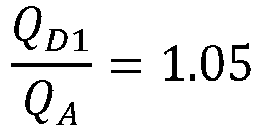
SD1=50 SA=210 RD1=0.0500 m1/m0 =10 M1/M0 =10 RA=0.1230 Comparative Ternary material 
SB= 175 SC= 150 RB=0.1200 / M1/M0 =10 Example 1 RC=0.1250 Comparative Example2 Ternary material 
SD1= 165 SA=210 RD1=0.0500 m1/m0 =7.5 M1/M0 =10 RA=0.1230 Comparative Example3 Ternary material 
SD1=30 SA=210 RD1=0.00007 m1/m0 =10 M1/M0 =10 RA=0.1230 Comparative Example4 Ternary material 
SD1=700 SA=210 RD1=0.20 m1/m0 =10 M1/M0 =10 RA=0.1230 Table 2: Battery performance test results of this test example Group Energy density (Wh/kg) DC impedance (mΩ) Number of cycles (cycles) Embodiment 1 250 2.0 1750 Embodiment2 250 2.0 1800 Embodiment3 250 1.9 1780 Embodiment4 245 2.1 1600 Embodiment5 245 2.5 1500 Embodiment6 245 2.2 1700 Embodiment7 245 2.1 1750 Embodiment8 245 2.5 1450 Embodiment9 245 2.4 1600 Embodiment 10 250 2.1 1700 Embodiment 11 250 2.1 1680 Embodiment 12 245 2.3 1650 Embodiment 13 250 2.1 1700 Embodiment 14 250 2.1 1680 Comparative Example 1 250 2.8 1300 Comparative Example2 235 2.9 1250 Comparative Example3 235 2.9 1260 Comparative Example4 235 2.9 1200 - Table 2 shows the test results of the relevant performance of the batteries prepared in embodiments 1 to 14 and comparative examples 1 to 4.
- Comparing the test results of performance corresponding to embodiment 1 and comparative example 1, it can be seen from table 2 that under the same conditions of other materials and operations for preparing a battery, the battery prepared in embodiment 1 has a low impedance level and excellent energy density and cycle performance. However, the composite cell prepared in comparative example 1 is provided with only second positive electrode sheets, the cycle performance of the battery thus obtained was significantly lower than that of the battery prepared in embodiment 1. It is thus indicated that, compared to comparative example 1, the battery provided in embodiment 1 is provided with first positive electrode sheets, which have stable structures and can fully utilize the advantages of different positive electrode active materials, so as to effectively alleviate problems such as impedance and current imbalance occurring among different types of positive electrode active materials in the composite cell, thereby improving the energy density and cycle performance of the battery.
- Comparing the test results of performance corresponding to embodiment 1 and comparative example 2, it can be seen from tables 1 and 2 that under the same conditions of other materials and operations for preparing a battery, the battery prepared in embodiment 1 has a low impedance level and excellent energy density and cycle performance. However, in the first positive electrode sheet prepared in comparative example 2, the mass proportion of the first positive electrode active material exceeds the range of 10% to 50%, and the cycle performance of the battery thus obtained was significantly lower than that of the battery prepared in embodiment 1. It is thus indicated that, compared to comparative example 2, the battery provided in embodiment 1, by reasonably setting the proportion of the first positive electrode active material in the first positive electrode sheet, is beneficial to make the potential distribution of the first positive electrode sheet uniform, and alleviate the lithium deposition phenomenon caused by excessive local current density of the electrode sheet, thereby improving the energy density and cycle performance of the battery.
- Comparing the test results of performance corresponding to embodiment 1 and comparative examples 3 and 4, it can be seen from tables 1 and 2 that under the same conditions of other materials and operations for preparing a battery, the battery prepared in embodiment 1 has a low impedance level and excellent energy density and cycle performance. However, the composite positive electrode active coating layer provided on the first positive electrode sheet prepared in comparative example 3 has an average single-side surface density SD1 less than 50 g/m2, and the specific surface resistance RD1 is less than 0.0001 Ω/mm2·g; the composite positive electrode active coating layer provided on the first positive electrode sheet prepared in comparative example 4 has an average single-side surface density SD1 greater than 650 g/m2, and the specific surface resistance RD1 was greater than 0.1500 Ω/mm2·g, and the cycle performance of the battery thus obtained was significantly lower than that of the battery prepared in embodiment 1. It is thus indicated that, compared to comparative examples 3 and 4, the battery provided in embodiment 1, by reasonably setting the surface density and the specific surface resistance of the composite positive electrode active coating layer in the first positive electrode sheet, is beneficial to make the potential distribution of the first positive electrode sheet uniform, and alleviate the lithium deposition phenomenon caused by excessive local current density of the electrode sheet, thereby improving the energy density and cycle performance of the battery.
- Comparing the test results of performance corresponding to embodiment 1 and embodiments 5 to 8, it can be seen from tables 1 and 2 that under the same conditions of other materials and operations for preparing a battery, in embodiments 5 and 8, the mass proportions of the first positive electrode active material to all positive electrode active materials in the composite cell are respectively less than 5%, greater than 40%, and the cycle performance of the battery thus obtained was lower than that of the battery prepared in embodiment 1. It is thus indicated that, compared to embodiments 5 and 8, the composite cell provided in embodiments 1, 6 to 7, by reasonably setting the content of the first positive electrode active material in the composite cell, is beneficial for improving the matching effect between different positive electrode active materials, achieving the overall current density uniformity of the composite cell, allowing the positive electrode active materials with different energy density to exert their synergistic advantages, thereby improving the energy density and cycle performance of the battery.
- Comparing the test results of performance corresponding to embodiment 1 and embodiments 9 to 12, it can be seen from tables 1 and 2 that under the same conditions of other materials and operations for preparing a battery, the positive electrode active coating layer provided on the second positive electrode sheet in embodiment 9 has an average single-side surface density SA less than 65 g/m2, and the specific surface resistance RA was less than 0.0002 Ω/mm2·g; the positive electrode active coating layer provided on the second positive electrode sheet in embodiment 12 has an average single-side surface density SA greater than 700 g/m2, and the specific areal resistance RA was greater than 0.2000 Ω/mm2·g, and the battery thus obtained had cycle performance lower than that of the battery prepared in embodiment 1. It is thus indicated that, compared to embodiments 9 and 12, the composite cell provided in
embodiments 1, 10 and 11 is designed by reasonably setting the surface density and specific surface resistance of the second positive electrode sheet, so that the second positive electrode sheet with a specific surface density and specific surface resistance has an excellent matching effect with the first positive electrode sheet, and can play a synergistic advantage with the first positive electrode sheet to ensure the uniformity of the current density among different positive electrode sheets, and avoid the phenomena such as unstable electrode sheet structure, lithium deposition, polarization, caused by poor matching effect of the electrode sheets, thereby improving the energy density and cycle performance of the battery.
Claims (11)
- A composite cell (1), comprising positive electrode sheets, wherein the number of the positive electrode sheets is greater than one; each positive electrode sheet satisfies a condition that a ratio of its capacity per unit area to a capacity per unit area of any other positive electrode sheet is 0.9 to 1.1;the positive electrode sheets comprise first positive electrode sheets (1-4), wherein positive electrode active materials contained in the first positive electrode sheet (1-4) comprise a first positive electrode active material and a second positive electrode active material, wherein an energy density of the first positive electrode active material is greater than that of the second positive electrode active material;wherein on each of the first positive electrode sheets (1-4), the mass of the first positive electrode active material is less than the mass of the second positive electrode active material, and
 wherein on each of the first positive electrode sheets (1-4), the number of layers of positive electrode active coating layers is greater than one, an average single-side surface density of the positive electrode active coating layer is 50 to 650 g/m2, and a specific surface resistance of the first positive electrode sheet (1-4) is 0.0001 to 0.1500 Ω/mm2·g; the positive electrode active coating layers comprise a first positive electrode active coating layer (1-41) and a second positive electrode active coating layer (1-42); wherein a positive electrode active material contained in the first positive electrode active coating layer (1-41) is the first positive electrode active material, and a positive electrode active material contained in the second positive electrode active coating layer (1-42) is the second positive electrode active material.
 - The composite cell (1) according to claim 1, wherein the positive electrode sheets further comprise second positive electrode sheets (1-1), wherein an average single-side surface density of a positive electrode active coating layer provided on the second positive electrode sheet (1-1) is 65 to 700 g/m2, and a specific face resistance of the second positive electrode sheet (1-1) is 0.0002 to 0.2000 Ω/mm2·g.
- The composite cell (1) according to claim 2, wherein

- The composite cell (1) according to claim 3, wherein the average single-side surface density of the positive electrode active coating layer provided on the first positive electrode sheet (1-4) is 100 to 500 g/m2, and the specific surface resistance of the first positive electrode sheet (1-4) is 0.0001 to 0.1200 Ω/mm2·g.
- The composite cell (1) according to claim 4, wherein the average single-side surface density of the positive electrode active coating layer provided on the second positive electrode sheet (1-1) is 200 to 600 g/m2, and the specific surface resistance of the second positive electrode sheet (1-1) is 0.0002 to 0.1600 Ω/mm2·g.
- The composite cell (1) according to claim 1, wherein the composite cell (1) satisfies a condition that:

- The composite cell (1) according to claim 1, wherein the first positive electrode active material is a ternary positive electrode material, and the second positive electrode active material comprises at least one of lithium iron phosphate, lithium manganese iron phosphate, and lithium manganate.
- The composite cell (1) according to claim 7, wherein on a same side of a current collector of the first positive electrode sheet (1-4), in a direction away from a surface of the current collector, the positive electrode active coating layer formed by the first positive electrode active material and the positive electrode active coating layer formed by the second positive electrode active material are arranged in sequence.
- The composite cell (1) according to claim 2, wherein the positive electrode active material contained in the second positive electrode sheet (1-1) comprises one of lithium iron phosphate, lithium manganese iron phosphate, and lithium manganate.
- The composite cell (1) according to claim 2, wherein the composite cell (1) satisfies a condition that:

- A battery (100), comprising a battery housing (10) and the composite cell (1) according to any one of claims 1 to 10, wherein the composite cell (1) is arranged in the battery housing (10).
Applications Claiming Priority (1)
| Application Number | Priority Date | Filing Date | Title |
|---|---|---|---|
| CN202311674827.6A CN117497826A (en) | 2023-12-06 | 2023-12-06 | Composite battery core and battery containing same |
Publications (1)
| Publication Number | Publication Date |
|---|---|
| EP4567926A1 true EP4567926A1 (en) | 2025-06-11 |
Family
ID=89680154
Family Applications (1)
| Application Number | Title | Priority Date | Filing Date |
|---|---|---|---|
| EP24215104.1A Pending EP4567926A1 (en) | 2023-12-06 | 2024-11-25 | Composite cell and battery containing same |
Country Status (5)
| Country | Link |
|---|---|
| US (1) | US20250192156A1 (en) |
| EP (1) | EP4567926A1 (en) |
| JP (1) | JP2025091361A (en) |
| CN (1) | CN117497826A (en) |
| WO (1) | WO2025118384A1 (en) |
Citations (1)
| Publication number | Priority date | Publication date | Assignee | Title |
|---|---|---|---|---|
| US20220006073A1 (en) * | 2018-11-05 | 2022-01-06 | Ningde Amperex Technology Limited | Cathode, electrochemical device and electronic device including the same |
Family Cites Families (8)
| Publication number | Priority date | Publication date | Assignee | Title |
|---|---|---|---|---|
| TWI679796B (en) * | 2017-12-27 | 2019-12-11 | 財團法人工業技術研究院 | Cathode of lithium ion battery |
| CN110556538B (en) * | 2018-06-01 | 2021-05-04 | 宁德时代新能源科技股份有限公司 | Positive electrode sheet and lithium ion battery |
| CN116435448A (en) * | 2022-01-04 | 2023-07-14 | 宁德时代新能源科技股份有限公司 | Positive electrode sheet, secondary battery, battery module, battery pack, and power consumption device |
| CN116960274A (en) * | 2022-04-14 | 2023-10-27 | 华为技术有限公司 | Cathode plates, secondary batteries, electronic equipment and mobile devices |
| CN116404110A (en) * | 2023-03-20 | 2023-07-07 | 珠海冠宇动力电池有限公司 | A kind of positive plate and battery |
| CN116598598A (en) * | 2023-05-23 | 2023-08-15 | 湖北亿纬动力有限公司 | Composite battery cell and battery using same |
| CN116826182B (en) * | 2023-05-23 | 2025-07-04 | 湖北亿纬动力有限公司 | A composite battery cell suitable for sodium ion battery and a sodium ion battery using the same |
| CN116666644A (en) * | 2023-06-28 | 2023-08-29 | 珠海冠宇电池股份有限公司 | A kind of positive pole piece and lithium ion battery |
-
2023
- 2023-12-06 CN CN202311674827.6A patent/CN117497826A/en active Pending
- 2023-12-28 WO PCT/CN2023/142822 patent/WO2025118384A1/en active Pending
-
2024
- 2024-11-06 JP JP2024194394A patent/JP2025091361A/en active Pending
- 2024-11-25 EP EP24215104.1A patent/EP4567926A1/en active Pending
- 2024-11-29 US US18/963,784 patent/US20250192156A1/en active Pending
Patent Citations (1)
| Publication number | Priority date | Publication date | Assignee | Title |
|---|---|---|---|---|
| US20220006073A1 (en) * | 2018-11-05 | 2022-01-06 | Ningde Amperex Technology Limited | Cathode, electrochemical device and electronic device including the same |
Also Published As
| Publication number | Publication date |
|---|---|
| CN117497826A (en) | 2024-02-02 |
| WO2025118384A1 (en) | 2025-06-12 |
| JP2025091361A (en) | 2025-06-18 |
| US20250192156A1 (en) | 2025-06-12 |
Similar Documents
| Publication | Publication Date | Title |
|---|---|---|
| EP4679531A1 (en) | Composite lithium manganese iron phosphate positive electrode material and preparation method therefor and use thereof | |
| CN116365013A (en) | Secondary battery and electric equipment | |
| EP4489106B1 (en) | Negative electrode sheet, battery cell, battery pack, and electricity-consumption device | |
| CN116598598A (en) | Composite battery cell and battery using same | |
| EP4632825A1 (en) | A positive electrode plate, a lithium-ion battery, and an electrode device | |
| CN116706248A (en) | A combined cell and a battery using the same | |
| EP4567926A1 (en) | Composite cell and battery containing same | |
| CN117199575B (en) | Negative electrode plate, preparation method thereof and sodium ion battery | |
| EP4734176A1 (en) | Positive electrode material, positive electrode sheet and lithium ion battery | |
| CN113066988A (en) | Negative pole piece and preparation method and application thereof | |
| CN116430257B (en) | A method for characterizing the electrical performance of lithium batteries and its application | |
| EP4432391A1 (en) | Positive electrode sheet for high-rate, long-cycle and high-safety lithium battery, preparation method therefor and application thereof | |
| EP4607640A1 (en) | Lithium secondary battery and electrical device | |
| CN116387446A (en) | Secondary battery and electricity utilization device | |
| JPH1167207A (en) | Negative electrode for lithium secondary battery | |
| CN116565207A (en) | Embedded conductive material and application thereof in battery | |
| EP3035433A1 (en) | Lead-acid battery | |
| EP4629315A1 (en) | Positive electrode plate and lithium-ion battery using positive electrode plate | |
| Chen | Development of VRLA batteries for high rate discharge applications | |
| EP4604243A1 (en) | Battery cell and preparation method therefor, and lithium battery comprising battery cell | |
| CN121601636B (en) | Lithium ion battery positive electrode based on composite positive electrode active material, and preparation method and application thereof | |
| US20260081152A1 (en) | Electrochemical stack, cell pack, and methods of using electrochemical stack and cell pack | |
| US20230116145A1 (en) | Electrode assembly | |
| EP4567913A2 (en) | Battery core, battery core preparation method, starting battery for fuel engine, and vehicle | |
| Mahajan et al. | Development of Model for Split Electrode Lead Carbon Battery |
Legal Events
| Date | Code | Title | Description |
|---|---|---|---|
| PUAI | Public reference made under article 153(3) epc to a published international application that has entered the european phase |
Free format text: ORIGINAL CODE: 0009012 |
|
| STAA | Information on the status of an ep patent application or granted ep patent |
Free format text: STATUS: REQUEST FOR EXAMINATION WAS MADE |
|
| 17P | Request for examination filed |
Effective date: 20241125 |
|
| AK | Designated contracting states |
Kind code of ref document: A1 Designated state(s): AL AT BE BG CH CY CZ DE DK EE ES FI FR GB GR HR HU IE IS IT LI LT LU LV MC ME MK MT NL NO PL PT RO RS SE SI SK SM TR |