EP4567552A1 - Display apparatus - Google Patents
Display apparatus Download PDFInfo
- Publication number
- EP4567552A1 EP4567552A1 EP24209980.2A EP24209980A EP4567552A1 EP 4567552 A1 EP4567552 A1 EP 4567552A1 EP 24209980 A EP24209980 A EP 24209980A EP 4567552 A1 EP4567552 A1 EP 4567552A1
- Authority
- EP
- European Patent Office
- Prior art keywords
- hole
- display apparatus
- disposed
- camera module
- display
- Prior art date
- Legal status (The legal status is an assumption and is not a legal conclusion. Google has not performed a legal analysis and makes no representation as to the accuracy of the status listed.)
- Pending
Links
Images






Classifications
-
- G—PHYSICS
- G06—COMPUTING OR CALCULATING; COUNTING
- G06F—ELECTRIC DIGITAL DATA PROCESSING
- G06F1/00—Details not covered by groups G06F3/00 - G06F13/00 and G06F21/00
- G06F1/16—Constructional details or arrangements
- G06F1/1601—Constructional details related to the housing of computer displays, e.g. of CRT monitors, of flat displays
- G06F1/1605—Multimedia displays, e.g. with integrated or attached speakers, cameras, microphones
-
- G—PHYSICS
- G06—COMPUTING OR CALCULATING; COUNTING
- G06F—ELECTRIC DIGITAL DATA PROCESSING
- G06F1/00—Details not covered by groups G06F3/00 - G06F13/00 and G06F21/00
- G06F1/16—Constructional details or arrangements
- G06F1/1613—Constructional details or arrangements for portable computers
- G06F1/1633—Constructional details or arrangements of portable computers not specific to the type of enclosures covered by groups G06F1/1615 - G06F1/1626
- G06F1/1684—Constructional details or arrangements related to integrated I/O peripherals not covered by groups G06F1/1635 - G06F1/1675
- G06F1/1686—Constructional details or arrangements related to integrated I/O peripherals not covered by groups G06F1/1635 - G06F1/1675 the I/O peripheral being an integrated camera
-
- G—PHYSICS
- G09—EDUCATION; CRYPTOGRAPHY; DISPLAY; ADVERTISING; SEALS
- G09F—DISPLAYING; ADVERTISING; SIGNS; LABELS OR NAME-PLATES; SEALS
- G09F9/00—Indicating arrangements for variable information in which the information is built-up on a support by selection or combination of individual elements
-
- G—PHYSICS
- G02—OPTICS
- G02B—OPTICAL ELEMENTS, SYSTEMS OR APPARATUS
- G02B7/00—Mountings, adjusting means, or light-tight connections, for optical elements
- G02B7/02—Mountings, adjusting means, or light-tight connections, for optical elements for lenses
-
- H—ELECTRICITY
- H04—ELECTRIC COMMUNICATION TECHNIQUE
- H04M—TELEPHONIC COMMUNICATION
- H04M1/00—Substation equipment, e.g. for use by subscribers
- H04M1/02—Constructional features of telephone sets
- H04M1/0202—Portable telephone sets, e.g. cordless phones, mobile phones or bar type handsets
- H04M1/026—Details of the structure or mounting of specific components
- H04M1/0264—Details of the structure or mounting of specific components for a camera module assembly
-
- H—ELECTRICITY
- H04—ELECTRIC COMMUNICATION TECHNIQUE
- H04N—PICTORIAL COMMUNICATION, e.g. TELEVISION
- H04N23/00—Cameras or camera modules comprising electronic image sensors; Control thereof
- H04N23/50—Constructional details
- H04N23/51—Housings
-
- H—ELECTRICITY
- H04—ELECTRIC COMMUNICATION TECHNIQUE
- H04N—PICTORIAL COMMUNICATION, e.g. TELEVISION
- H04N23/00—Cameras or camera modules comprising electronic image sensors; Control thereof
- H04N23/50—Constructional details
- H04N23/55—Optical parts specially adapted for electronic image sensors; Mounting thereof
-
- H—ELECTRICITY
- H04—ELECTRIC COMMUNICATION TECHNIQUE
- H04N—PICTORIAL COMMUNICATION, e.g. TELEVISION
- H04N23/00—Cameras or camera modules comprising electronic image sensors; Control thereof
- H04N23/57—Mechanical or electrical details of cameras or camera modules specially adapted for being embedded in other devices
-
- H—ELECTRICITY
- H05—ELECTRIC TECHNIQUES NOT OTHERWISE PROVIDED FOR
- H05K—PRINTED CIRCUITS; CASINGS OR CONSTRUCTIONAL DETAILS OF ELECTRIC APPARATUS; MANUFACTURE OF ASSEMBLAGES OF ELECTRICAL COMPONENTS
- H05K5/00—Casings, cabinets or drawers for electric apparatus
- H05K5/02—Details
- H05K5/0217—Mechanical details of casings
-
- H—ELECTRICITY
- H05—ELECTRIC TECHNIQUES NOT OTHERWISE PROVIDED FOR
- H05K—PRINTED CIRCUITS; CASINGS OR CONSTRUCTIONAL DETAILS OF ELECTRIC APPARATUS; MANUFACTURE OF ASSEMBLAGES OF ELECTRICAL COMPONENTS
- H05K7/00—Constructional details common to different types of electric apparatus
- H05K7/14—Mounting supporting structure in casing or on frame or rack
- H05K7/1417—Mounting supporting structure in casing or on frame or rack having securing means for mounting boards, plates or wiring boards
Definitions
- the present disclosure relates to a display apparatus, and more specifically, to a display apparatus having a structure in which a camera module can be mounted stably.
- Such display apparatuses include a liquid crystal display (LCD) device, a quantum dot display panel device (QD), a field emission display (FED) device, and an electro-wetting display (EWD) device, an organic light emitting diode (OLED) display apparatus, etc.
- LCD liquid crystal display
- QD quantum dot display panel device
- FED field emission display
- EWD electro-wetting display
- OLED organic light emitting diode
- the display apparatuses have been developed to be miniaturized so that users may carry the display apparatuses or to be mounted on movable devices such as vehicles, etc., and are being improved so that the users may use the display apparatuses more conveniently.
- a display apparatus may be provided with a camera module to capture external images.
- the conventional display apparatus When the conventional display apparatus is provided with the camera module, a separate area is provided to arrange the camera module. That is, the camera module is disposed at a separate location spaced from the display module.
- an area of the display module becomes smaller and the overall area of the display apparatus becomes greater to provide a separate area for arranging the camera module.
- recent display apparatuses may be disposed at a location at which the display module is disposed without a separate area in which the camera module is disposed.
- the present disclosure is directed to providing a display apparatus having a structure in which a camera module may be mounted stably.
- the present disclosure is directed to providing a display apparatus having a structure in which a camera module may be mounted simply.
- the present disclosure is directed to providing a display apparatus having a mounting structure of a camera module, which may be processed inexpensively.
- a display apparatus may include a camera module including a body and a lens barrel protruding from the body, in which a lens barrel is disposed at a location at which a first through hole formed in the display module is located, wherein the metal plate may include a second through hole which is formed at a location corresponding to the first through hole and in which the lens barrel is located, and a guide part disposed to surround the second through hole and protruding toward the camera module, wherein the guide part is configured to cooperate with the body of the camera module to position and guide the body of the camera module when the camera module is mounted in the display apparatus.
- the metal plate may be provided with a plurality of guide parts which are spaced apart from each other to surround the body and determine an arrangement location of the body.
- the metal plate may be provided with a formation hole for forming the guide part in the metal plate and the guide part is formed by bending a portion adjacent to the formation hole.
- the metal plate may include a rib formed at an edge of the second through hole in a circumferential direction of the second through hole and protruding toward the camera module.
- the rib may be formed by bending a portion in contact with the second through hole of the metal plate.
- a display apparatus may include a camera module including a body and a lens barrel protruding from the body, in which a lens barrel is disposed at a location at which a first through hole formed in the display module is located, a cover member disposed to cover the first through hole in front of the display module, and a chip on film (COF) having one side electrically connected to the display module and the other side electrically connected to the printed circuit board, wherein the metal plate may include a second through hole which is formed at a location corresponding to the first through hole and in which the lens barrel is located, a guide part disposed to surround the second through hole and protruding toward the camera module, the guide part is configured to cooperate with the body of the camera module to position and guide the body of the camera module when the camera module is mounted in the display apparatus, and a rib formed at an edge of the second through hole in a circumferential direction of the second through hole and protruding toward the camera module, the body includes a seating groove which is formed in a shape corresponding to
- the metal plate may be provided with a formation hole for forming the guide part in the metal plate and the guide part may be formed by bending a portion adjacent to the formation hole, and the rib may be formed by bending a portion in contact with the second through hole of the metal plate.
- first and second are used to describe various components, it goes without saying that the components are not limited by these terms. These terms are only used to distinguish one component from another component, and unless otherwise stated, it goes without saying that the first component may be the second component.
- forward a direction in which the user is located
- backward a direction opposite to the forward
- the display apparatus according to the embodiment may be mounted, for example, in a cockpit of a vehicle to provide a video or image required for driving to a driver and a passenger of the vehicle.
- the present disclosure is not limited thereto, and the display apparatus may be used while carried by the user rather than mounted on the vehicle.
- a display apparatus mounted on a vehicle will be described.
- FIG. 1 is a front view showing a display apparatus according to one embodiment.
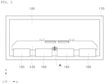
- FIG. 2 is a rear view showing the display apparatus according to one embodiment.
- a display apparatus may include a display module 110 (see FIG. 10 ), a metal plate 120, a cover member 150, a bezel 170, a printed circuit board 130, a chip-on-film (COF) 160, and a camera module 140.
- the display module 110 may be provided to display a video or image.
- the video or image to be displayed may be navigation information necessary for traveling, video captured by a camera mounted on the vehicle, or various other contents needed by a driver or passengers.
- a first through hole 111 through which a lens barrel 141 of the camera module 140 is disposed may be formed in an active area of the display panel 113 in the display module 110. Therefore, the lens barrel 141 may pass through the display module 110 to face the front of the display apparatus and capture a video.
- a specific structure of the display module 110 is described below.
- the metal plate 120 may be disposed behind the display module 110.
- the metal plate 120 may serve as a heat sink for cooling the display panel 113 by dissipating heat generated from the display panel 113 provided in the display module 110 to the outside.
- the metal plate 120 may be made of, for example, aluminum, copper, or a metal material containing the same, which has a high heat transfer rate. However, the present disclose is not limited thereto.
- the cover member 150 may be disposed to cover the first through hole 111 in front of the display module 110.
- the cover member 150 may be disposed at the frontmost portion of the display apparatus.
- the cover member 150 may be disposed in front of the display panel 113 to protect the display panel 113.
- the cover member 150 may be made of a transparent material to allow light emitted from the display panel 113 to pass through the cover member 150.
- the cover member 150 made of a transparent material may be incident on the lens barrel 141, a forward image of the display apparatus may be captured.
- the bezel 170 may be disposed to surround edges of the display module 110, the metal plate 120, and the cover member 150, couple the display module 110, the metal plate 120, and the cover member 150, and form a portion of the appearance of the display apparatus.
- the printed circuit board 130 may be disposed behind the metal plate 120.
- the printed circuit board 130 may be disposed behind the metal plate 120 and electrically connected to the display panel 113.
- the printed circuit board 130 may include the camera module 140, a device for communicating with external devices such as a main control module of a vehicle, a device for driving the display panel 113 so that the display panel 113 displays a video or image, etc., and provided with a circuit, and various other active and passive elements.
- the COF 160 may have one side electrically connected to the display module 110 and the other side electrically connected to the printed circuit board 130.
- the COF 160 may be attached to one surface of the display panel 113 of the display module 110 and electrically connected to the display module 110.
- the COF 160 may be disposed so that a portion is bent to surround an end portion of the metal plate 120.
- the COF 160 may be formed thinly and made of a flexible material to enable bending.
- the COF 160 may electrically connect the display panel 113 with the printed circuit board 130.
- the COF 160 may be provided with various active and passive elements and provided with a driving circuit for driving the display panel 113.
- the driving circuit for driving the display panel 113 may be provided to be dispersed to each of the printed circuit board 130 and the COF 160.
- the COF 160 may be provided with a driving element that forms at least a portion of the driving circuit of the display panel 113.
- a plurality of COFs 160 may be provided.
- the COFs 160 may be disposed to be spaced apart from each other.
- the camera module 140 is mounted on the display apparatus to capture the forward image of the display apparatus.
- the camera module 140 may have the lens barrel 141 disposed at a location at which the first through hole 111 formed in the display module 110 is located.
- the conventional display apparatus When the conventional display apparatus is provided with the camera module 140, a separate area in which the camera module 140 is disposed is provided. That is, the camera module 140 is disposed at a separate location spaced apart from the display module 110.
- the area of the display module 110 becomes smaller, and the overall area of the display apparatus becomes greater.
- recent camera module may be disposed at a location at which the display module 110 is disposed without a separate area in which the camera module 140 is disposed.
- the display apparatus according to the embodiment also has such a structure.
- the camera module 140 When the camera module 140 is disposed on the display module 110, there is a need for a structure in which the camera module 140 may be stably mounted on the display apparatus to maintain the location. This will be described in detail below.
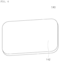
- FIG. 3 is a perspective view showing a front surface of the camera module 140 according to one embodiment.
- FIG. 4 is a perspective view showing a back surface of the camera module 140 according to one embodiment.
- the camera module 140 may include an auto focusing (AF) device, and an optical image stabilizing (OIS) device for correcting shaking of the camera module 140 due to an external impact.
- AF auto focusing
- OIS optical image stabilizing
- the camera module 140 may include a body 142 and the lens barrel 141.
- the body 142 may be connected to the printed circuit board 130 to receive electricity from the printed circuit board 130 and may communicate with a controller provided on the printed circuit board 130.
- the body 142 may be implemented with various elements and circuits for controlling the AF and OIS operations of the lens barrel 141.
- the lens barrel 141 may protrude from the body 142 and include at least one lens.
- the lens barrel 141 may increase the resolutions of images captured by arranging various types of a plurality of lenses.
- the body 142 may include a seating groove 1421.
- the seating groove 1421 may be formed in a shape corresponding to a rib 122 of the metal plate 120, and the rib 122 may be seated therein. As will be described below, the rib 122 may be formed to protrude from the metal plate 120 in a ring shape.
- the seating groove 1421 may be formed in a ring shape to correspond to the shape of the rib 122, formed by a recessed portion of the body 142, and formed to surround the lens barrel 141.
- FIG. 5 is a partial view showing a state in which a preliminary through hole 121' is formed in the metal plate 120 according to one embodiment.
- FIG. 6 is a partial view showing a state in which the processing is performed in FIG. 5 to form a second through hole 121.
- the metal plate 120 is a structure for mounting the camera module 140 and may include the second through hole 121 and a guide part 124.
- the second through hole 121 may be formed at a location corresponding to the first through hole 111, and the lens barrel 141 may be disposed therein.
- the second through hole 121 may be formed, for example, by punching the metal plate 120.
- the lens barrel 141 may be disposed in the second through hole 121 to pass through the metal plate 120 to view the front of the display apparatus.
- the body 142 may be disposed behind the metal plate 120.
- the guide part 124 may be disposed to surround the second through hole 121 and may protrude toward the camera module 140.
- a plurality of guide parts 124 may be provided and spaced apart from each other to surround the body 142 and determine the arrangement location of the body 142.
- the plurality of guide parts 124 may be disposed at edges of the body 142 to support the body 142. Therefore, the plurality of guide parts 124 need to be disposed at locations that may stably support the body 142.
- the body 142 may be formed in a hexahedral shape, and each of the plurality of guide parts 124 may be disposed to support each side of the body 142.
- the body 142 may be disposed inside the plurality of guide parts 124, and thus the plurality of guide parts 124 may determine the arrangement location of the body 142.
- the body 142 mounted on the guide part 124 may be stably supported by the guide part 124 to maintain the mounted location. Meanwhile, the rib 122 of the metal plate 120, which will be described below, may determine the arrangement location of the body 142 together with the guide part 124.
- the metal plate 120 is a structure for mounting the camera module 140 and may additionally include the rib 122.
- the rib 122 may be formed at an edge of the second through hole 121 in circumferential direction of the second through hole 121 in the metal plate 120 and may protrude toward the camera module 140.
- the camera module 140 may be mounted at a designed location of the metal plate 120 to maintain the mounted location.
- the rib 122 and the seating groove 1421 may be manufactured in corresponding shapes.
- the rib 122 and the seating groove 1421 may be provided in a ring shape surrounding the lens barrel 141. Meanwhile, a plurality of guide parts 124 may be provided to surround the rib 122.
- the rib 122 may be formed by bending a portion of the metal plate 120, and since the rib 122 is provided in a ring shape, thereby making ending processing easier compared to other shapes and thus easily manufacturing the rib 122.
- the camera module 140 may be stably mounted on the metal plate 120 by the guide part 124 and the rib 122.
- the lens barrel 141 may be disposed inside the rib 122.
- the body 142 may be disposed to be surrounded by the plurality of guide parts 124, and an end portion of the rib 122 may be seated in the seating groove 1421.
- the camera module 140 may be stably mounted on the metal plate 120 by a dual structure of the guide part 124 and the rib 122 to maintain the mounted location.
- the mounted location is determined by the guide part 124 and the rib 122. Therefore, a worker simply fits the camera module 140 into the guide part 124 and the rib 122 without separately setting the arrangement location of the camera module 140. Therefore, the camera module 140 may be easily mounted on the display apparatus.
- the guide part 124 and the rib 122 are formed on the metal plate 120
- a method such as casting, die casting, or injection may be used. However, the methods may require a separate mold frame.
- the camera module 140 may be very small compared to the overall size of the display apparatus, and the guide part 124 and the rib 122 for mounting the camera module 140 may also be provided in very small sizes. Therefore, it is difficult to form the very small guide part 124 and rib 122 on the metal plate 120 using a method such as casting, and there is a high possibility of the occurrence of defects.
- the metal plate 120 may be provide with a formation hole 123 for forming the guide part 124 in the metal plate 120 and the guide part 124 is formed by bending a portion adjacent to the formation hole 123.
- the metal plate 120 is made of a metal having excellent malleability and ductility, the guide part 124 and the rib 122 that have a relatively small volume may be formed through bending processing.
- the formation hole 123 for forming the guide part 124 may be formed at a designed location on the metal plate 120 through punching processing.
- a plurality of formation holes 123 may be formed in a "U" shape at locations spaced apart from each other to surround the second through hole 121 or the preliminary through hole 121'.
- a second area 124' which becomes the guide part 124 later, may be formed by the formation hole 123.
- the second area 124' may be bent to protrude forward, and thus the second area 124' may become the guide part 124.
- Such bending processing may be performed manually by the worker or using an automated bending machine.
- the rib 122 may be formed by bending a portion of the metal plate 120 that is in contact with the second through hole 121.
- the second through hole 121 may be formed to have an expanded diameter as the rib 122 having a relatively small diameter is formed through bending.
- the preliminary through hole 121' having the relatively small diameter may be formed at a designed location of the metal plate 120 through the punching processing.
- a first area 122' which is provided in a ring shape and will become the rib 122 in the future, may be present at a location surrounding the preliminary through hole 121' of the metal plate 120.
- the first area 122' may protrude forward, and thus the first area 122 may become the rib 122.
- the first area 122' may protrude to form the rib 122.
- the preliminary through hole 121' having the relatively small diameter may have the expanded diameter as the rib 122 is formed through bending and thus become the second through hole having a relatively great diameter.
- the metal plate 120 Since the metal plate 120 has excellent malleability and ductility, even when such bending processing is performed, the first area 122' of the metal plate 120 may be smoothly deformed without disconnection to become the rib 122.
- the guide part 124 and the rib 122 may be easily formed through the punching processing and the bending processing according to the above-described method.
- the guide part 124 and the rib 122 may be formed on the metal plate 120 through the punching processing and the bending processing, and a separate mold frame for casting, die casting, injection, etc. cannot be used.
- the processing for forming the guide part 124 and the rib 122 can be easy, the manufacturing process of the display apparatus can be simplified, and manufacturing costs can be reduced.
- the guide part 124 and the rib 122 that have relatively small volume throughout the display apparatus are formed, it is possible to significantly reduce the defect rate compared to the method such as casting.
- the camera module 140 can increase the area efficiency and space efficiency of the display apparatus no matter in which part of the display module 110 is disposed. However, the camera module 140 may be disposed, for example, at a location overlapping the printed circuit board 130.
- a hole into which the lens barrel 141 is inserted may be formed in the printed circuit board 130, and the lens barrel 141 may be placed in the hole to be disposed at the location overlapping the printed circuit board 130.
- a cable 126 for electrically connecting the camera module 140 with the printed circuit board 130 may be easily installed, and compared to a case where the camera module 140 is not disposed on the printed circuit board 130, the cable 126 can be shortened, thereby increasing space efficiency in the display apparatus.
- the structure in which the camera module 140 is disposed on the printed circuit board 130 that is, the structure in which the camera module 140 and the printed circuit board 130 are disposed to overlap each other will be described in detail.
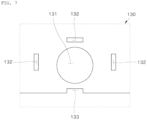
- FIG. 7 is a partial view showing a portion in which a third through hole 131 is formed in the printed circuit board 130 according to one embodiment.
- FIG. 8 is a partial view showing a state in which the metal plate 120 and the printed circuit board 130 are coupled.
- the printed circuit board 130 may include the third through hole 131 and an insertion hole 132 to arrange the camera module 140.
- the third through hole 131 may be formed at a location corresponding to the second through hole 121, and the lens barrel 141 may be disposed therein.
- the lens barrel 141 may be disposed in the third through hole 131 to pass through the printed circuit board 130 and may also pass through the first through hole 111 and the second through hole 121 to face the display apparatus and capture the image.
- the rib 122 may be inserted into the third through hole 131.
- the rib 122 may be disposed to protrude forward through the third through hole 131, and the rib 122 may be fitted into the seating groove 1421 of the body 142.
- the camera module 140 and the metal plate 120 disposed with the printed circuit board 130 interposed therebetween may be coupled.
- the insertion hole 132 may be formed at a location corresponding to the guide part 124, and the guide part 124 may be inserted therein.
- the number of insertion holes 132 may be equal to or smaller than the number of guide parts 124. That is, when a recessed groove 133 to be described below is formed in the printed circuit board 130 and the guide part 124 is inserted therein, the number of insertion holes 132 may be smaller than the number of guide parts 124.
- the insertion hole 132 may be disposed to surround at least a portion of the third through hole 131.
- the printed circuit board 130 may be stably disposed at the designed location on the metal plate 120.
- the guide part 124 passing through the insertion hole 132 may protrude forward, and the body 142 may be fitted into the guide part 124 and supported by the guide part 124.
- the camera module 140 and the metal plate 120 disposed with the printed circuit board 130 interposed therebetween may be coupled.
- the printed circuit board 130 may include the recessed groove 133 separately from the insertion hole 132 to arrange the camera module 140.
- the end portion of the printed circuit board 130 may be recessed to form the recessed groove 133, and the guide part 124 may be inserted into the recessed groove 133.
- the guide part 124 needs to be disposed at the end portion of the printed circuit board 130 according to the arrangement location of the camera module 140 on the printed circuit board 130.
- the recessed groove 133 may be formed at the end portion of the printed circuit board 130, and some of the plurality of guide parts 124 may be inserted into the recessed groove 133 to protrude forward.
- the guide part 124 passing through the recessed groove 133 may protrude forward, and the body 142 may be fitted into the guide part 124 and supported by the guide part 124.
- FIG. 9 is an enlarged view showing portion A in FIG. 2 .
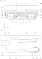
- FIG. 10 is a cross-sectional view along line BB in FIG. 9 .
- the lens barrel 141 may face the front of the display apparatus through the first through hole 111 and may be disposed in the second through hole 121 and the third through hole 131.
- the cover member 150 closing the first through hole 111 may be made of a transparent material and may not block the view of the lens barrel 141.
- An attachment unit may be provided to fixedly mount the camera module 140 to the display apparatus.
- the body 142 of the camera module 140 may be in contact with the back surface of the printed circuit board 130, and thus may be attached to the printed circuit board 130 using a double-sided tape between the body 142 of the camera module 140 and the printed circuit board 130.
- the display module 110 may include a back plate 112, a display panel 113, a polarizer 114, and a fixing member 115.
- the back plate 112 may be placed in front of the metal plate 120.
- the back plate 112 may be disposed between the display panel 113 and the metal plate 120.
- the back plate 112 may be attached to the rear surface of the display panel 113, thereby suppressing the display panel 113 from being damaged by being bent. That is, the back plate 112 may serve to reinforce the rigidity of the display panel 113.
- the back plate 112 may be provided, for example, in the form of a film and attached to the display panel 113.
- the present disclosure is not limited thereto.
- the display panel 113 may be disposed in front of the back plate 112 to display a video or image.
- the video or image to be displayed may be navigation information necessary for traveling, video captured by a camera mounted on the vehicle, or various other contents needed by a driver or passengers.
- the display panel 113 may be electrically connected to the COF 160 and electrically connected to the printed circuit board 130 through the COF 160. Therefore, the controller and driving elements provided on the COF 160 and/or the printed circuit board 130 may control the operation of the display panel 113.
- the polarizer 114 may be disposed in front of the display panel 113.
- the polarizer 114 may be disposed between the display panel 113 and the fixing member 115.
- the polarizer 114 can increase outdoor visibility and contrast ratio for images displayed on the display panel 113 by preventing reflection of external light.
- the fixing member 115 may be disposed in front of the polarizer 114.
- the fixing member 115 may be disposed between the cover member 150 and the display panel 113 to attach the display panel 113 to the cover member 150.
- the fixing member 115 may be made of a transparent material because light emitted from the display panel 113 should pass through the fixing member 115.
- the fixing member 115 may be made of or include a material that is transparent and has good adhesion, such as an optical clear adhesive (OCA), an optical clear resin (OCR), or a pressure sensitive adhesive (PSA).
- OCA optical clear adhesive
- OCR optical clear resin
- PSA pressure sensitive adhesive
- the first through hole 111 may be formed by removing the display panel 113, the polarizer 114, and the fixing member 115.
- a light blocking layer for preventing light leakage may be disposed on side surface portions of the display panel 113, the polarizer 114, and the fixing member 115 that are disposed in the first through hole 111.
- a cushion plate for cushioning may be disposed between the back plate 112 and the metal plate 120.
- the cushion plate may mitigate the impact applied to various parts of the display apparatus and include an embossing layer and a cushion layer.
- the embossing layer may be disposed behind the back plate 112.
- the embossing layer may be disposed to be bonded to the back plate 112 and formed as an adhesive layer having an embossing pattern.
- the embossing pattern of the embossing layer may be, for example, an uneven structure formed on the surface.
- the embossing layer may be in direct contact with the back plate 112 to fix the cushion layer to the back plate 112, the embossing layer may serve as an adhesive layer by containing an adhesive component.
- the embossing layer may be made of or include materials such as the OCA, the OCR, or the PSA.
- the embossing layer may have the thickness of at least 40 ⁇ m or more for an adhesion function and bubble prevention.
- the cushion layer may be disposed between the embossing layer and the metal plate 120.
- the cushion layer may be formed of a foam tape or a foam pad.
- the cushion layer may serve to mitigate the impact of various parts that may be in contact with the cushion plate.
- the cushion layer can reinforce the rigidity of the cushion plate.
- the cushion plate may include a porous member in another embodiment.
- the porous member may be attached to the embossing layer or cushion layer to become an element forming the cushion plate.
- the porous member may be a metal foam.
- the porous member together with the cushion layer may serve as a kind of a cushion means, thereby mitigating the impact of various parts that may be in contact with the cushion plate.
- the porous member may be made of a metal material to reinforce the rigidity of the cushion plate.
- the lens barrel 141 may be disposed in the first through hole 111 formed in the display module 110 and disposed under the display panel 113 to form a separation space between the lens barrel 141 and the cover member 150.
- FIG. 11 is a view showing a portion of the printed circuit board 130 according to one embodiment.
- the camera module 140 may be electrically connected to the printed circuit board 130, the operation thereof may be controlled by the controller provided on the printed circuit board 130, and the camera module 140 may receive electricity from the printed circuit board 130.
- the printed circuit board 130 may be provided with a connector 125.
- the display apparatus may include the cable 126 having one end coupled to the connector 125 and the other end coupled to the camera module 140 to electrically connect the camera module 140 with the printed circuit board 130.
- the camera module 140 may be disposed at a location overlapping the printed circuit board 130 in a front-rear direction of the display apparatus.
- the connector 125 may be provided on the printed circuit board 130.
- the cable 126 connecting the camera module 140 with the printed circuit board 130 may be disposed to overlap the printed circuit board 130 in the front-rear direction of the display apparatus.
- the cable 126 may be provided relatively short, and an extra space for arranging the cable 126 can be minimized. In addition, there is no need to provide a separate space for arranging the cable 126 on the xy plane perpendicular to the front-rear direction.
- a display apparatus may include a display module for displaying a video, a metal plate disposed behind the display module, a printed circuit board disposed behind a metal plate, and a camera module in which a lens barrel is disposed at a location at which a first through hole formed in the display module is located, in which the metal plate may include a second through hole which is formed at a location corresponding to the first through hole and in which the lens barrel is disposed, and a guide part disposed to surround the second through hole and protruding toward the camera module.
- the camera module may include a body, and the lens barrel protruding from the body and including at least one lens, in which a plurality of guide parts may be provided in the metal plate and spaced apart from each other to surround the body and determine an arrangement location of the body.
- the body may be formed in a hexahedral shape, and each of the plurality of guide parts may be disposed to support each side of the body.
- the guide part may be provided with a formation hole for forming the guide part in the metal plate and formed by bending a portion adjacent to the formation hole.
- the printed circuit board may include a third through hole which is formed at a location corresponding to the second through hole and in which the lens barrel is disposed, and an insertion hole which is formed at a location corresponding to the guide part and into which the guide part is inserted.
- the metal plate may include a rib formed at an edge of the second through hole in a circumferential direction of the second through hole and protruding toward the camera module.
- the rib may be formed by bending a portion of the metal plate in contact with the second through hole.
- the second through hole may be formed to have an expanded diameter as the rib having a relatively small diameter is formed through bending.
- the body may include a seating groove which is formed in a shape corresponding to the rib and in which the rib is seated.
- the rib and the seating groove may be provided in a ring shape surrounding the lens barrel.
- the lens barrel may be disposed inside the rib, the body may be disposed to be surrounded by a plurality of the guide parts, and an end portion of the rib may be seated in the seating groove.
- the printed circuit board may include a recessed groove which is formed by a recessed end portion and into which the guide part is inserted.
- the plurality of guide parts may be provided to surround the rib.
- the display module may include a back plate disposed in front of the metal plate, a display panel disposed in front of the back plate and displaying an image, a polarizer disposed in front of the display panel, and a fixing member disposed in front of the polarizer.
- the display apparatus may include a cover member disposed to cover the first through hole in front of the display module.
- a display apparatus may include a display module for displaying a video, a metal plate disposed behind the display module, a printed circuit board disposed behind the metal plate, a camera module in which a lens barrel is disposed at a location at which a first through hole disposed in the display module is located, a cover member disposed to cover the first through hole in front of the display module, and a chip on film (COF) having one side electrically connected to the display module and the other side electrically connected to the printed circuit board, in which the metal plate may include a second through hole which is formed at a location corresponding to the first through hole and in which the lens barrel is disposed, a guide part disposed to surround the second through hole and protruding toward the camera module, and a rib formed in a circumferential direction of the second through hole at an edge of the second through hole and protruding toward the camera module.
- COF chip on film
- the metal plate may be provided with a formation hole for forming the guide part in the metal plate and the guide part is formed by bending a portion adjacent to the formation hole, and the rib may be formed by bending a portion of the metal plate in contact with the second through hole.
- the printed circuit board may include a third through hole which is formed at a location corresponding to the second through hole and in which the lens barrel is disposed, an insertion hole which is formed at a location corresponding to the guide part and into which the guide part is inserted, and a recessed groove which is formed by a recessed end portion and into which the guide part is inserted.
- the camera module may include a body, and the lens barrel protruding from the body and including at least one lens, in which the body may include a seating groove which is formed in a shape corresponding to the rib and in which the rib is seated.
- the camera module can be stably mounted on the metal plate by the guide part and the rib.
- the lens barrel may be disposed inside the rib.
- the body may be disposed to be surrounded by a plurality of guide parts, and an end portion of the rib may be seated in a seating groove.
- the camera module can be stably mounted on the metal plate to maintain the mounted location by the dual structure of the guide part and the rib.
- the mounting located is determined by the guide part and the rib, and thus the worker simply fits the camera module into the guide part and the rib without separately setting the arrangement location of the camera module. Therefore, the camera module can be easily mounted on the display apparatus.
- the guide part and the rib are formed on the metal plate through punching processing and bending processing, and a separate mold for casting, die casting, injection, etc. cannot be used.
- the processing to form the guide part and the rib can be easy, the manufacturing process of the display apparatus can be simplified, and the manufacturing costs thereof can be reduced.
- the guide part and rib having the relatively small in volume in the entirety of the display apparatus are formed, it is possible to significantly reduce the defect rate compared to the method such as casting.
Landscapes
- Engineering & Computer Science (AREA)
- Multimedia (AREA)
- Signal Processing (AREA)
- Theoretical Computer Science (AREA)
- Physics & Mathematics (AREA)
- General Physics & Mathematics (AREA)
- Computer Hardware Design (AREA)
- Microelectronics & Electronic Packaging (AREA)
- General Engineering & Computer Science (AREA)
- Human Computer Interaction (AREA)
- Optics & Photonics (AREA)
- Camera Bodies And Camera Details Or Accessories (AREA)
- Devices For Indicating Variable Information By Combining Individual Elements (AREA)
- Studio Devices (AREA)
Abstract
The present disclosure relates to a display apparatus, and more specifically, to a display apparatus having a structure in which a camera module can be mounted stably. A display apparatus according to one embodiment may include a display module for displaying a video, a metal plate disposed behind the display module, a printed circuit board disposed behind a metal plate, and a camera module which includes a body and a lens barrel protruding from the body and in which a lens barrel is disposed at a location at which a first through hole formed in the display module is located, in which the metal plate may include a second through hole which is formed at a location corresponding to the first through hole and in which the lens barrel is disposed, and a guide part disposed to surround the second through hole and protruding toward the camera module. The guide part is configured to cooperate with the body of the camera module to position and guide the body of the camera module when the camera module is mounted in the display apparatus.
Description
- The present disclosure relates to a display apparatus, and more specifically, to a display apparatus having a structure in which a camera module can be mounted stably.
- Contents described in this section simply provide background information on the present disclosure and do not constitute the related art.
- In the full-fledged information age, the field of display apparatuses for visually displaying electrical information signals is developing rapidly, and research for developing performance, such as thinness, lightweight, and lower power consumption, for various display apparatuses is being continuously conducted.
- Such display apparatuses include a liquid crystal display (LCD) device, a quantum dot display panel device (QD), a field emission display (FED) device, and an electro-wetting display (EWD) device, an organic light emitting diode (OLED) display apparatus, etc.
- The display apparatuses have been developed to be miniaturized so that users may carry the display apparatuses or to be mounted on movable devices such as vehicles, etc., and are being improved so that the users may use the display apparatuses more conveniently.
- A display apparatus may be provided with a camera module to capture external images.
- When the conventional display apparatus is provided with the camera module, a separate area is provided to arrange the camera module. That is, the camera module is disposed at a separate location spaced from the display module.
- In the case of the conventional structure, an area of the display module becomes smaller and the overall area of the display apparatus becomes greater to provide a separate area for arranging the camera module.
- Therefore, even when the display apparatus becomes greater, the size of a screen on which a user may actually view an image becomes smaller, thereby degrading the area efficiency and volume efficiency of the display apparatus.
- To compensate the disadvantages of the related art, recent display apparatuses may be disposed at a location at which the display module is disposed without a separate area in which the camera module is disposed.
- When the camera module is disposed on the display module, there is a need for a structure in which the location of the camera module mounted in the display apparatus can be maintained stably.
- Therefore, the present disclosure is directed to providing a display apparatus having a structure in which a camera module may be mounted stably.
- In addition, the present disclosure is directed to providing a display apparatus having a structure in which a camera module may be mounted simply.
- In addition, the present disclosure is directed to providing a display apparatus having a mounting structure of a camera module, which may be processed inexpensively.
- Objects of the present disclosure are not limited to the above-described objects, and other objects and advantages of the present disclosure which are not mentioned can be understood by the following description and more dearly understood by embodiments of the present disclosure. In addition, it will be able to be easily seen that the objects and advantages of the present disclosure may be achieved by devices and combinations thereof that are described in the claims.
- One embodiment of a display apparatus may include a camera module including a body and a lens barrel protruding from the body, in which a lens barrel is disposed at a location at which a first through hole formed in the display module is located, wherein the metal plate may include a second through hole which is formed at a location corresponding to the first through hole and in which the lens barrel is located, and a guide part disposed to surround the second through hole and protruding toward the camera module, wherein the guide part is configured to cooperate with the body of the camera module to position and guide the body of the camera module when the camera module is mounted in the display apparatus.
- The metal plate may be provided with a plurality of guide parts which are spaced apart from each other to surround the body and determine an arrangement location of the body.
- The metal plate may be provided with a formation hole for forming the guide part in the metal plate and the guide part is formed by bending a portion adjacent to the formation hole.
- The metal plate may include a rib formed at an edge of the second through hole in a circumferential direction of the second through hole and protruding toward the camera module.
- The rib may be formed by bending a portion in contact with the second through hole of the metal plate.
- One embodiment of a display apparatus may include a camera module including a body and a lens barrel protruding from the body, in which a lens barrel is disposed at a location at which a first through hole formed in the display module is located, a cover member disposed to cover the first through hole in front of the display module, and a chip on film (COF) having one side electrically connected to the display module and the other side electrically connected to the printed circuit board, wherein the metal plate may include a second through hole which is formed at a location corresponding to the first through hole and in which the lens barrel is located, a guide part disposed to surround the second through hole and protruding toward the camera module, the guide part is configured to cooperate with the body of the camera module to position and guide the body of the camera module when the camera module is mounted in the display apparatus, and a rib formed at an edge of the second through hole in a circumferential direction of the second through hole and protruding toward the camera module, the body includes a seating groove which is formed in a shape corresponding to the rib and in which the rib is seated to maintain the mounted position of the camera module when the camera module is mounted in the display apparatus.
- The metal plate may be provided with a formation hole for forming the guide part in the metal plate and the guide part may be formed by bending a portion adjacent to the formation hole, and the rib may be formed by bending a portion in contact with the second through hole of the metal plate.
-
-
FIG. 1 is a front view showing a display apparatus according to one embodiment. -
FIG. 2 is a rear view showing the display apparatus according to one embodiment. -
FIG. 3 is a perspective view showing a front surface of a camera module according to one embodiment. -
FIG. 4 is a perspective view showing a rear surface of the camera module according to one embodiment. -
FIG. 5 is a partial view showing a state in which a preliminary through hole is formed in a metal plate according to one embodiment. -
FIG. 6 is a partial view showing a state in which the processing is performed inFIG. 5 to form a second through hole. -
FIG. 7 is a partial view showing a portion in which a third through hole is formed in a printed circuit board according to one embodiment. -
FIG. 8 is a partial view showing a state in which the metal plate and the printed circuit board are coupled. -
FIG. 9 is an enlarged view showing portion A inFIG. 2 . -
FIG. 10 is a cross-sectional view along line BB inFIG. 9 . -
FIG. 11 is a view showing a portion of the printed circuit board according to one embodiment. - The above-described objects, features, and advantages will be described below in detail with reference to the accompanying drawings, and thus those skilled in the art to which the present disclosure pertains will be able to easily carry out the technical spirit of the present disclosure. In describing the present disclosure, when it is determined that a detailed description of the known technology related to the present disclosure may unnecessarily obscure the gist of the present disclosure, a detailed description thereof will be omitted. Hereinafter, exemplary embodiments according to the present disclosure will be described in detail with reference to the accompanying drawings. In the drawings, the same reference numerals are used to denote the same or similar components.
- Although terms such as first and second are used to describe various components, it goes without saying that the components are not limited by these terms. These terms are only used to distinguish one component from another component, and unless otherwise stated, it goes without saying that the first component may be the second component.
- Throughout the specification, unless otherwise stated, each component may be singular or plural.
- The singular expression used herein includes the plural expression unless the context clearly dictates otherwise. In the application, terms such as "composed of' or "comprising" should not be construed as necessarily including all of the various components or operations described in the specification and should be construed as not including some of the components or some of the operations or further including additional components or operations.
- Throughout the specification, when "A and/or B" is described, this means A, B, or A and B unless otherwise specified, and when "C to D" is described, this means C or more and D or less unless otherwise specified.
- In the following description, when the user views the display apparatus in a state in which the display apparatus is disposed to be generally used, a direction in which the user is located is referred to as "forward," and a direction opposite to the forward is referred to as "backward."
- In addition, "vertically," "upper side," "lower side," "above," "under" indicates a location or direction of each component in a state in which the display apparatus is disposed to be generally used. In the drawing, "forward" indicates a +Z-axis direction, "backward" indicates a -Z-a>cis direction, and "vertically" indicates an X-axis direction.
- The display apparatus according to the embodiment may be mounted, for example, in a cockpit of a vehicle to provide a video or image required for driving to a driver and a passenger of the vehicle. However, the present disclosure is not limited thereto, and the display apparatus may be used while carried by the user rather than mounted on the vehicle. Hereinafter, for example, a display apparatus mounted on a vehicle will be described.
-
FIG. 1 is a front view showing a display apparatus according to one embodiment.FIG. 2 is a rear view showing the display apparatus according to one embodiment. - A display apparatus according to one embodiment may include a display module 110 (see
FIG. 10 ), ametal plate 120, acover member 150, abezel 170, a printedcircuit board 130, a chip-on-film (COF) 160, and acamera module 140. - The
display module 110 may be provided to display a video or image. The video or image to be displayed may be navigation information necessary for traveling, video captured by a camera mounted on the vehicle, or various other contents needed by a driver or passengers. - A first through
hole 111 through which alens barrel 141 of thecamera module 140 is disposed may be formed in an active area of thedisplay panel 113 in thedisplay module 110. Therefore, thelens barrel 141 may pass through thedisplay module 110 to face the front of the display apparatus and capture a video. A specific structure of thedisplay module 110 is described below. - The
metal plate 120 may be disposed behind thedisplay module 110. Themetal plate 120 may serve as a heat sink for cooling thedisplay panel 113 by dissipating heat generated from thedisplay panel 113 provided in thedisplay module 110 to the outside. - The
metal plate 120 may be made of, for example, aluminum, copper, or a metal material containing the same, which has a high heat transfer rate. However, the present disclose is not limited thereto. - The
cover member 150 may be disposed to cover the first throughhole 111 in front of thedisplay module 110. Thecover member 150 may be disposed at the frontmost portion of the display apparatus. Thecover member 150 may be disposed in front of thedisplay panel 113 to protect thedisplay panel 113. Thecover member 150 may be made of a transparent material to allow light emitted from thedisplay panel 113 to pass through thecover member 150. - Therefore, since the light passing through the
cover member 150 made of a transparent material may be incident on thelens barrel 141, a forward image of the display apparatus may be captured. - The
bezel 170 may be disposed to surround edges of thedisplay module 110, themetal plate 120, and thecover member 150, couple thedisplay module 110, themetal plate 120, and thecover member 150, and form a portion of the appearance of the display apparatus. - The printed
circuit board 130 may be disposed behind themetal plate 120. The printedcircuit board 130 may be disposed behind themetal plate 120 and electrically connected to thedisplay panel 113. - The printed
circuit board 130 may include thecamera module 140, a device for communicating with external devices such as a main control module of a vehicle, a device for driving thedisplay panel 113 so that thedisplay panel 113 displays a video or image, etc., and provided with a circuit, and various other active and passive elements. - The
COF 160 may have one side electrically connected to thedisplay module 110 and the other side electrically connected to the printedcircuit board 130. TheCOF 160 may be attached to one surface of thedisplay panel 113 of thedisplay module 110 and electrically connected to thedisplay module 110. - The
COF 160 may be disposed so that a portion is bent to surround an end portion of themetal plate 120. TheCOF 160 may be formed thinly and made of a flexible material to enable bending. - The
COF 160 may electrically connect thedisplay panel 113 with the printedcircuit board 130. TheCOF 160 may be provided with various active and passive elements and provided with a driving circuit for driving thedisplay panel 113. - The driving circuit for driving the
display panel 113 may be provided to be dispersed to each of the printedcircuit board 130 and theCOF 160. TheCOF 160 may be provided with a driving element that forms at least a portion of the driving circuit of thedisplay panel 113. A plurality ofCOFs 160 may be provided. TheCOFs 160 may be disposed to be spaced apart from each other. - The
camera module 140 is mounted on the display apparatus to capture the forward image of the display apparatus. Thecamera module 140 may have thelens barrel 141 disposed at a location at which the first throughhole 111 formed in thedisplay module 110 is located. - When the conventional display apparatus is provided with the
camera module 140, a separate area in which thecamera module 140 is disposed is provided. That is, thecamera module 140 is disposed at a separate location spaced apart from thedisplay module 110. - In the case of the conventional structure, to provide a separate area in which the
camera module 140 is disposed, the area of thedisplay module 110 becomes smaller, and the overall area of the display apparatus becomes greater. - Therefore, even when the display apparatus becomes greater, the size of a screen on which a user may actually view an image becomes smaller, thereby degrading the area efficiency and volume efficiency of the display apparatus.
- To compensate the disadvantages of the related art, recent camera module may be disposed at a location at which the
display module 110 is disposed without a separate area in which thecamera module 140 is disposed. The display apparatus according to the embodiment also has such a structure. - When the
camera module 140 is disposed on thedisplay module 110, there is a need for a structure in which thecamera module 140 may be stably mounted on the display apparatus to maintain the location. This will be described in detail below. - First, the
camera module 140 according to one embodiment will be described.FIG. 3 is a perspective view showing a front surface of thecamera module 140 according to one embodiment.FIG. 4 is a perspective view showing a back surface of thecamera module 140 according to one embodiment. - To capture a high resolution image, the
camera module 140 may include an auto focusing (AF) device, and an optical image stabilizing (OIS) device for correcting shaking of thecamera module 140 due to an external impact. - The
camera module 140 may include abody 142 and thelens barrel 141. Thebody 142 may be connected to the printedcircuit board 130 to receive electricity from the printedcircuit board 130 and may communicate with a controller provided on the printedcircuit board 130. In addition, thebody 142 may be implemented with various elements and circuits for controlling the AF and OIS operations of thelens barrel 141. - The
lens barrel 141 may protrude from thebody 142 and include at least one lens. For example, thelens barrel 141 may increase the resolutions of images captured by arranging various types of a plurality of lenses. - The
body 142 may include aseating groove 1421. Theseating groove 1421 may be formed in a shape corresponding to arib 122 of themetal plate 120, and therib 122 may be seated therein. As will be described below, therib 122 may be formed to protrude from themetal plate 120 in a ring shape. - Therefore, the
seating groove 1421 may be formed in a ring shape to correspond to the shape of therib 122, formed by a recessed portion of thebody 142, and formed to surround thelens barrel 141. -
FIG. 5 is a partial view showing a state in which a preliminary through hole 121' is formed in themetal plate 120 according to one embodiment.FIG. 6 is a partial view showing a state in which the processing is performed inFIG. 5 to form a second throughhole 121. - The
metal plate 120 is a structure for mounting thecamera module 140 and may include the second throughhole 121 and aguide part 124. The second throughhole 121 may be formed at a location corresponding to the first throughhole 111, and thelens barrel 141 may be disposed therein. The second throughhole 121 may be formed, for example, by punching themetal plate 120. - The
lens barrel 141 may be disposed in the second throughhole 121 to pass through themetal plate 120 to view the front of the display apparatus. Thebody 142 may be disposed behind themetal plate 120. - The
guide part 124 may be disposed to surround the second throughhole 121 and may protrude toward thecamera module 140. A plurality ofguide parts 124 may be provided and spaced apart from each other to surround thebody 142 and determine the arrangement location of thebody 142. - The plurality of
guide parts 124 may be disposed at edges of thebody 142 to support thebody 142. Therefore, the plurality ofguide parts 124 need to be disposed at locations that may stably support thebody 142. - For example, the
body 142 may be formed in a hexahedral shape, and each of the plurality ofguide parts 124 may be disposed to support each side of thebody 142. With this structure, thebody 142 may be disposed inside the plurality ofguide parts 124, and thus the plurality ofguide parts 124 may determine the arrangement location of thebody 142. - The
body 142 mounted on theguide part 124 may be stably supported by theguide part 124 to maintain the mounted location. Meanwhile, therib 122 of themetal plate 120, which will be described below, may determine the arrangement location of thebody 142 together with theguide part 124. - The
metal plate 120 is a structure for mounting thecamera module 140 and may additionally include therib 122. Therib 122 may be formed at an edge of the second throughhole 121 in circumferential direction of the second throughhole 121 in themetal plate 120 and may protrude toward thecamera module 140. - Since the
rib 122 is seated in theseating groove 1421 formed in thebody 142 of thecamera module 140, thecamera module 140 may be mounted at a designed location of themetal plate 120 to maintain the mounted location. - Since the
rib 122 is fitted into theseating groove 1421, therib 122 and theseating groove 1421 may be manufactured in corresponding shapes. For example, therib 122 and theseating groove 1421 may be provided in a ring shape surrounding thelens barrel 141. Meanwhile, a plurality ofguide parts 124 may be provided to surround therib 122. - The
rib 122 may be formed by bending a portion of themetal plate 120, and since therib 122 is provided in a ring shape, thereby making ending processing easier compared to other shapes and thus easily manufacturing therib 122. - In an embodiment, the
camera module 140 may be stably mounted on themetal plate 120 by theguide part 124 and therib 122. Specifically, thelens barrel 141 may be disposed inside therib 122. - In this case, the
body 142 may be disposed to be surrounded by the plurality ofguide parts 124, and an end portion of therib 122 may be seated in theseating groove 1421. Thecamera module 140 may be stably mounted on themetal plate 120 by a dual structure of theguide part 124 and therib 122 to maintain the mounted location. - In an embodiment, when the
camera module 140 is mounted on the display apparatus, the mounted location is determined by theguide part 124 and therib 122. Therefore, a worker simply fits thecamera module 140 into theguide part 124 and therib 122 without separately setting the arrangement location of thecamera module 140. Therefore, thecamera module 140 may be easily mounted on the display apparatus. - When the
guide part 124 and therib 122 are formed on themetal plate 120, a method such as casting, die casting, or injection may be used. However, the methods may require a separate mold frame. - In addition, the
camera module 140 may be very small compared to the overall size of the display apparatus, and theguide part 124 and therib 122 for mounting thecamera module 140 may also be provided in very small sizes. Therefore, it is difficult to form the verysmall guide part 124 andrib 122 on themetal plate 120 using a method such as casting, and there is a high possibility of the occurrence of defects. - Hereinafter, an example in which the
guide part 124 and therib 122 are formed by using bending processing, which is simpler and has a lower defect rate than the method such as casting, will be described in detail. - The
metal plate 120 may be provide with aformation hole 123 for forming theguide part 124 in themetal plate 120 and theguide part 124 is formed by bending a portion adjacent to theformation hole 123. - Since the
metal plate 120 is made of a metal having excellent malleability and ductility, theguide part 124 and therib 122 that have a relatively small volume may be formed through bending processing. - Referring to
FIG. 5 , theformation hole 123 for forming theguide part 124 may be formed at a designed location on themetal plate 120 through punching processing. For example, a plurality of formation holes 123 may be formed in a "U" shape at locations spaced apart from each other to surround the second throughhole 121 or the preliminary through hole 121'. - In this case, a second area 124', which becomes the
guide part 124 later, may be formed by theformation hole 123. In the bending processing, the second area 124' may be bent to protrude forward, and thus the second area 124' may become theguide part 124. - Such bending processing may be performed manually by the worker or using an automated bending machine.
- The
rib 122 may be formed by bending a portion of themetal plate 120 that is in contact with the second throughhole 121. The second throughhole 121 may be formed to have an expanded diameter as therib 122 having a relatively small diameter is formed through bending. - Referring to
FIG. 5 , first, the preliminary through hole 121' having the relatively small diameter may be formed at a designed location of themetal plate 120 through the punching processing. A first area 122', which is provided in a ring shape and will become therib 122 in the future, may be present at a location surrounding the preliminary through hole 121' of themetal plate 120. - Through the bending processing, the first area 122' may protrude forward, and thus the
first area 122 may become therib 122. For example, when a pressure is applied by inserting a rod-shaped tool having a diameter that is the same as or very similar to that of the second through hole into the preliminary through hole 121', the first area 122' may protrude to form therib 122. - In this case, the preliminary through hole 121' having the relatively small diameter may have the expanded diameter as the
rib 122 is formed through bending and thus become the second through hole having a relatively great diameter. - Since the
metal plate 120 has excellent malleability and ductility, even when such bending processing is performed, the first area 122' of themetal plate 120 may be smoothly deformed without disconnection to become therib 122. - The
guide part 124 and therib 122 may be easily formed through the punching processing and the bending processing according to the above-described method. - In an embodiment, the
guide part 124 and therib 122 may be formed on themetal plate 120 through the punching processing and the bending processing, and a separate mold frame for casting, die casting, injection, etc. cannot be used. - Therefore, the processing for forming the
guide part 124 and therib 122 can be easy, the manufacturing process of the display apparatus can be simplified, and manufacturing costs can be reduced. In addition, when theguide part 124 and therib 122 that have relatively small volume throughout the display apparatus are formed, it is possible to significantly reduce the defect rate compared to the method such as casting. - The
camera module 140 can increase the area efficiency and space efficiency of the display apparatus no matter in which part of thedisplay module 110 is disposed. However, thecamera module 140 may be disposed, for example, at a location overlapping the printedcircuit board 130. - Specifically, a hole into which the
lens barrel 141 is inserted may be formed in the printedcircuit board 130, and thelens barrel 141 may be placed in the hole to be disposed at the location overlapping the printedcircuit board 130. - When the
camera module 140 is disposed on the printedcircuit board 130, acable 126 for electrically connecting thecamera module 140 with the printedcircuit board 130 may be easily installed, and compared to a case where thecamera module 140 is not disposed on the printedcircuit board 130, thecable 126 can be shortened, thereby increasing space efficiency in the display apparatus. - Hereinafter, the structure in which the
camera module 140 is disposed on the printedcircuit board 130, that is, the structure in which thecamera module 140 and the printedcircuit board 130 are disposed to overlap each other will be described in detail. -
FIG. 7 is a partial view showing a portion in which a third throughhole 131 is formed in the printedcircuit board 130 according to one embodiment.FIG. 8 is a partial view showing a state in which themetal plate 120 and the printedcircuit board 130 are coupled. - The printed
circuit board 130 may include the third throughhole 131 and aninsertion hole 132 to arrange thecamera module 140. The third throughhole 131 may be formed at a location corresponding to the second throughhole 121, and thelens barrel 141 may be disposed therein. - The
lens barrel 141 may be disposed in the third throughhole 131 to pass through the printedcircuit board 130 and may also pass through the first throughhole 111 and the second throughhole 121 to face the display apparatus and capture the image. - The
rib 122 may be inserted into the third throughhole 131. Therib 122 may be disposed to protrude forward through the third throughhole 131, and therib 122 may be fitted into theseating groove 1421 of thebody 142. With this structure, thecamera module 140 and themetal plate 120 disposed with the printedcircuit board 130 interposed therebetween may be coupled. - The
insertion hole 132 may be formed at a location corresponding to theguide part 124, and theguide part 124 may be inserted therein. The number ofinsertion holes 132 may be equal to or smaller than the number ofguide parts 124. That is, when a recessedgroove 133 to be described below is formed in the printedcircuit board 130 and theguide part 124 is inserted therein, the number ofinsertion holes 132 may be smaller than the number ofguide parts 124. - For example, like a case where the
rib 122 surrounds the second throughhole 121, theinsertion hole 132 may be disposed to surround at least a portion of the third throughhole 131. - By inserting the
guide part 124 into theinsertion hole 132, the printedcircuit board 130 may be stably disposed at the designed location on themetal plate 120. In addition, theguide part 124 passing through theinsertion hole 132 may protrude forward, and thebody 142 may be fitted into theguide part 124 and supported by theguide part 124. With this structure, thecamera module 140 and themetal plate 120 disposed with the printedcircuit board 130 interposed therebetween may be coupled. - The printed
circuit board 130 may include the recessedgroove 133 separately from theinsertion hole 132 to arrange thecamera module 140. The end portion of the printedcircuit board 130 may be recessed to form the recessedgroove 133, and theguide part 124 may be inserted into the recessedgroove 133. - The
guide part 124 needs to be disposed at the end portion of the printedcircuit board 130 according to the arrangement location of thecamera module 140 on the printedcircuit board 130. In the case of this structure, the recessedgroove 133 may be formed at the end portion of the printedcircuit board 130, and some of the plurality ofguide parts 124 may be inserted into the recessedgroove 133 to protrude forward. - Like the
guide part 124 passing through theinsertion hole 132, theguide part 124 passing through the recessedgroove 133 may protrude forward, and thebody 142 may be fitted into theguide part 124 and supported by theguide part 124. -
FIG. 9 is an enlarged view showing portion A inFIG. 2 .FIG. 10 is a cross-sectional view along line BB inFIG. 9 . As shown inFIG. 9 , thelens barrel 141 may face the front of the display apparatus through the first throughhole 111 and may be disposed in the second throughhole 121 and the third throughhole 131. - The
cover member 150 closing the first throughhole 111 may be made of a transparent material and may not block the view of thelens barrel 141. - An attachment unit may be provided to fixedly mount the
camera module 140 to the display apparatus. For example, thebody 142 of thecamera module 140 may be in contact with the back surface of the printedcircuit board 130, and thus may be attached to the printedcircuit board 130 using a double-sided tape between thebody 142 of thecamera module 140 and the printedcircuit board 130. - The
display module 110 according to one embodiment may include aback plate 112, adisplay panel 113, apolarizer 114, and a fixingmember 115. - The
back plate 112 may be placed in front of themetal plate 120. Theback plate 112 may be disposed between thedisplay panel 113 and themetal plate 120. Theback plate 112 may be attached to the rear surface of thedisplay panel 113, thereby suppressing thedisplay panel 113 from being damaged by being bent. That is, theback plate 112 may serve to reinforce the rigidity of thedisplay panel 113. - The
back plate 112 may be provided, for example, in the form of a film and attached to thedisplay panel 113. However, the present disclosure is not limited thereto. - The
display panel 113 may be disposed in front of theback plate 112 to display a video or image. The video or image to be displayed may be navigation information necessary for traveling, video captured by a camera mounted on the vehicle, or various other contents needed by a driver or passengers. - The
display panel 113 may be electrically connected to theCOF 160 and electrically connected to the printedcircuit board 130 through theCOF 160. Therefore, the controller and driving elements provided on theCOF 160 and/or the printedcircuit board 130 may control the operation of thedisplay panel 113. - The
polarizer 114 may be disposed in front of thedisplay panel 113. Thepolarizer 114 may be disposed between thedisplay panel 113 and the fixingmember 115. Thepolarizer 114 can increase outdoor visibility and contrast ratio for images displayed on thedisplay panel 113 by preventing reflection of external light. - The fixing
member 115 may be disposed in front of thepolarizer 114. The fixingmember 115 may be disposed between thecover member 150 and thedisplay panel 113 to attach thedisplay panel 113 to thecover member 150. The fixingmember 115 may be made of a transparent material because light emitted from thedisplay panel 113 should pass through the fixingmember 115. - Therefore, the fixing
member 115 may be made of or include a material that is transparent and has good adhesion, such as an optical clear adhesive (OCA), an optical clear resin (OCR), or a pressure sensitive adhesive (PSA). - The first through
hole 111 may be formed by removing thedisplay panel 113, thepolarizer 114, and the fixingmember 115. A light blocking layer for preventing light leakage may be disposed on side surface portions of thedisplay panel 113, thepolarizer 114, and the fixingmember 115 that are disposed in the first throughhole 111. - Meanwhile, a cushion plate for cushioning may be disposed between the
back plate 112 and themetal plate 120. The cushion plate may mitigate the impact applied to various parts of the display apparatus and include an embossing layer and a cushion layer. - The embossing layer may be disposed behind the
back plate 112. The embossing layer may be disposed to be bonded to theback plate 112 and formed as an adhesive layer having an embossing pattern. The embossing pattern of the embossing layer may be, for example, an uneven structure formed on the surface. - Since the embossing layer may be in direct contact with the
back plate 112 to fix the cushion layer to theback plate 112, the embossing layer may serve as an adhesive layer by containing an adhesive component. The embossing layer may be made of or include materials such as the OCA, the OCR, or the PSA. - The embossing layer may have the thickness of at least 40 µm or more for an adhesion function and bubble prevention.
- The cushion layer may be disposed between the embossing layer and the
metal plate 120. The cushion layer may be formed of a foam tape or a foam pad. The cushion layer may serve to mitigate the impact of various parts that may be in contact with the cushion plate. In addition, the cushion layer can reinforce the rigidity of the cushion plate. - The cushion plate may include a porous member in another embodiment. The porous member may be attached to the embossing layer or cushion layer to become an element forming the cushion plate. The porous member may be a metal foam.
- The porous member together with the cushion layer may serve as a kind of a cushion means, thereby mitigating the impact of various parts that may be in contact with the cushion plate. In addition, the porous member may be made of a metal material to reinforce the rigidity of the cushion plate.
- The
lens barrel 141 may be disposed in the first throughhole 111 formed in thedisplay module 110 and disposed under thedisplay panel 113 to form a separation space between thelens barrel 141 and thecover member 150. -
FIG. 11 is a view showing a portion of the printedcircuit board 130 according to one embodiment. Thecamera module 140 may be electrically connected to the printedcircuit board 130, the operation thereof may be controlled by the controller provided on the printedcircuit board 130, and thecamera module 140 may receive electricity from the printedcircuit board 130. - For electrical connection between the
camera module 140 and the printedcircuit board 130, the printedcircuit board 130 may be provided with aconnector 125. In addition, the display apparatus may include thecable 126 having one end coupled to theconnector 125 and the other end coupled to thecamera module 140 to electrically connect thecamera module 140 with the printedcircuit board 130. - In an embodiment, the
camera module 140 may be disposed at a location overlapping the printedcircuit board 130 in a front-rear direction of the display apparatus. In addition, theconnector 125 may be provided on the printedcircuit board 130. - With this structure, the
cable 126 connecting thecamera module 140 with the printedcircuit board 130 may be disposed to overlap the printedcircuit board 130 in the front-rear direction of the display apparatus. - Therefore, the
cable 126 may be provided relatively short, and an extra space for arranging thecable 126 can be minimized. In addition, there is no need to provide a separate space for arranging thecable 126 on the xy plane perpendicular to the front-rear direction. - By arranging the
camera module 140 to overlap the printedcircuit board 130, it is possible to minimize the extra space for arranging thecable 126, thereby increasing the area efficiency and space efficiency of the display apparatus. - A display apparatus according to one embodiment may include a display module for displaying a video, a metal plate disposed behind the display module, a printed circuit board disposed behind a metal plate, and a camera module in which a lens barrel is disposed at a location at which a first through hole formed in the display module is located, in which the metal plate may include a second through hole which is formed at a location corresponding to the first through hole and in which the lens barrel is disposed, and a guide part disposed to surround the second through hole and protruding toward the camera module.
- The camera module may include a body, and the lens barrel protruding from the body and including at least one lens, in which a plurality of guide parts may be provided in the metal plate and spaced apart from each other to surround the body and determine an arrangement location of the body.
- The body may be formed in a hexahedral shape, and each of the plurality of guide parts may be disposed to support each side of the body.
- The guide part may be provided with a formation hole for forming the guide part in the metal plate and formed by bending a portion adjacent to the formation hole.
- The printed circuit board may include a third through hole which is formed at a location corresponding to the second through hole and in which the lens barrel is disposed, and an insertion hole which is formed at a location corresponding to the guide part and into which the guide part is inserted.
- The metal plate may include a rib formed at an edge of the second through hole in a circumferential direction of the second through hole and protruding toward the camera module.
- The rib may be formed by bending a portion of the metal plate in contact with the second through hole.
- The second through hole may be formed to have an expanded diameter as the rib having a relatively small diameter is formed through bending.
- The body may include a seating groove which is formed in a shape corresponding to the rib and in which the rib is seated.
- The rib and the seating groove may be provided in a ring shape surrounding the lens barrel.
- The lens barrel may be disposed inside the rib, the body may be disposed to be surrounded by a plurality of the guide parts, and an end portion of the rib may be seated in the seating groove.
- The printed circuit board may include a recessed groove which is formed by a recessed end portion and into which the guide part is inserted.
- The plurality of guide parts may be provided to surround the rib.
- The display module may include a back plate disposed in front of the metal plate, a display panel disposed in front of the back plate and displaying an image, a polarizer disposed in front of the display panel, and a fixing member disposed in front of the polarizer.
- The display apparatus may include a cover member disposed to cover the first through hole in front of the display module.
- A display apparatus according to another embodiment may include a display module for displaying a video, a metal plate disposed behind the display module, a printed circuit board disposed behind the metal plate, a camera module in which a lens barrel is disposed at a location at which a first through hole disposed in the display module is located, a cover member disposed to cover the first through hole in front of the display module, and a chip on film (COF) having one side electrically connected to the display module and the other side electrically connected to the printed circuit board, in which the metal plate may include a second through hole which is formed at a location corresponding to the first through hole and in which the lens barrel is disposed, a guide part disposed to surround the second through hole and protruding toward the camera module, and a rib formed in a circumferential direction of the second through hole at an edge of the second through hole and protruding toward the camera module.
- The metal plate may be provided with a formation hole for forming the guide part in the metal plate and the guide part is formed by bending a portion adjacent to the formation hole, and the rib may be formed by bending a portion of the metal plate in contact with the second through hole.
- The printed circuit board may include a third through hole which is formed at a location corresponding to the second through hole and in which the lens barrel is disposed, an insertion hole which is formed at a location corresponding to the guide part and into which the guide part is inserted, and a recessed groove which is formed by a recessed end portion and into which the guide part is inserted.
- The camera module may include a body, and the lens barrel protruding from the body and including at least one lens, in which the body may include a seating groove which is formed in a shape corresponding to the rib and in which the rib is seated.
- In the display apparatus according to the present disclosure, the camera module can be stably mounted on the metal plate by the guide part and the rib. Specifically, the lens barrel may be disposed inside the rib.
- In this case, the body may be disposed to be surrounded by a plurality of guide parts, and an end portion of the rib may be seated in a seating groove. The camera module can be stably mounted on the metal plate to maintain the mounted location by the dual structure of the guide part and the rib.
- In addition, in the display apparatus according to the present disclosure, when the camera module is mounted on the display apparatus, the mounting located is determined by the guide part and the rib, and thus the worker simply fits the camera module into the guide part and the rib without separately setting the arrangement location of the camera module. Therefore, the camera module can be easily mounted on the display apparatus.
- In addition, in the display apparatus according to the present disclosure, the guide part and the rib are formed on the metal plate through punching processing and bending processing, and a separate mold for casting, die casting, injection, etc. cannot be used.
- Therefore, the processing to form the guide part and the rib can be easy, the manufacturing process of the display apparatus can be simplified, and the manufacturing costs thereof can be reduced. In addition, when the guide part and rib having the relatively small in volume in the entirety of the display apparatus are formed, it is possible to significantly reduce the defect rate compared to the method such as casting.
- Specific effects together with the above-described effects are described together with a description of the following detailed matters for carrying out the invention.
- Although the present disclosure has been described above with reference to exemplary drawings, the present disclosure is not limited by the embodiments and drawings disclosed in the specification, and it is apparent that various modifications can be made by those skilled in the art within the scope of the technical spirit of the present disclosure. In addition, even when the operational effects according to the configuration of the present disclosure have not been explicitly described in the description of the embodiments of the present disclosure, it goes without saying that the effects predictable by the corresponding configuration should be recognized.
- The present disclosure also comprises the following clauses:
- Clause 1. A display apparatus comprising:
- a display module configured to display a video;
- a metal plate disposed behind the display module;
- a printed circuit board disposed behind the metal plate; and
- a camera module including a body and a lens barrel protruding from the body, in which the lens barrel is disposed at a location at which a first through hole formed in the display module is located,
- wherein the metal plate includes:
- a second through hole which is formed at a location corresponding to the first through hole and in which the lens barrel is located; and
- a guide part disposed to surround the second through hole and protruding toward the camera module, wherein the guide part is configured to cooperate with the body of the camera module to position and guide the body of the camera module when the camera module is mounted in the display apparatus.
- Clause 2. The display apparatus of clause 1, wherein the lens barrel includes at least one lens,
the metal plate is proved with a plurality of guide parts which are spaced apart from each other to surround the body and determine an arrangement location of the body. - Clause 3. The display apparatus of any preceding clause, wherein the body is formed in a hexahedral shape, and each of the plurality of guide parts is disposed to support each side of the body of the camera module.
- Clause 4. The display apparatus of any preceding clause, wherein the metal plate is provided with a formation hole for forming the guide part in the metal plate and the guide part is formed by bending a portion adjacent to the formation hole.
- Clause 5. The display apparatus of any preceding clause, wherein the printed circuit board includes:
- a third through hole which is formed at a location corresponding to the second through hole and in which the lens barrel is located; and
- an insertion hole which is formed at a location corresponding to the guide part and into which the guide part is inserted.
- Clause 6. The display apparatus of any preceding clause, wherein the metal plate includes a rib formed at an edge of the second through hole in a circumferential direction of the second through hole and protruding toward the camera module, the body includes a seating groove which is formed in a shape corresponding to the rib and in which the rib is seated to maintain the mounted position of the camera module when the camera module is mounted in the display apparatus.
- Clause 7. The display apparatus of any preceding clause, wherein the rib is formed by bending a portion in contact with the second through hole of the metal plate.
- Clause 8. The display apparatus of any preceding clause, wherein the second through hole is formed to have an expanded diameter as the rib having a relatively small diameter is formed through bending,
- Clause 9. The display apparatus of any preceding clause, wherein the rib and the seating groove are provided in a ring shape surrounding the lens barrel.
- Clause 10. The display apparatus of any preceding clause, wherein the lens barrel is disposed inside the rib,
- the body is disposed to be surrounded by a plurality of guide parts, and
- an end portion of the rib is seated in the seating groove.
- Clause 11. The display apparatus of any preceding clause, wherein the printed circuit board includes a recessed groove which is formed by a recessed end portion and into which some of the plurality of guide parts is inserted.
- Clause 12. The display apparatus of any preceding clause, wherein the plurality of guide parts are provided to surround the rib.
- Clause 13. The display apparatus of any preceding clause, wherein the display module includes:
- a back plate disposed in front of the metal plate;
- a display panel disposed in front of the back plate and configured to display the video;
- a polarizer disposed in front of the display panel; and
- a fixing member disposed in front of the polarizer.
- Clause 14. The display apparatus of any preceding clause, further comprising a cover member disposed to cover the first through hole in front of the display module.
- Clause 15. The display apparatus of any preceding clause, further comprising a chip on film (COF) having one side electrically connected to the display module and the other side electrically connected to the printed circuit board.
- Clause 16. A display apparatus comprising:
- a display module configured to display a video;
- a metal plate disposed behind the display module;
- a printed circuit board disposed behind the metal plate;
- a camera module including a body and a lens barrel protruding from the body, in which a lens barrel is disposed at a location at which a first through hole formed in the display module is located;
- a cover member disposed to cover the first through hole in front of the display module; and
- a chip on film (COF) having one side electrically connected to the display module and the other side electrically connected to the printed circuit board,
- wherein the metal plate includes:
- a second through hole which is formed at a location corresponding to the first through hole and in which the lens barrel is located;
- a guide part disposed to surround the second through hole and protruding toward the camera module, wherein the guide part is configured to cooperate with the body of the camera module to position and guide the body of the camera module when the camera module is mounted in the display apparatus; and
- a rib formed at an edge of the second through hole in a circumferential direction of the second through hole and protruding toward the camera module, wherein the body includes a seating groove which is formed in a shape corresponding to the rib and in which the rib is seated to maintain the mounted position of the camera module when the camera module is mounted in the display apparatus.
- Clause 17. The display apparatus of clause 16, wherein the metal plate is provided with a formation hole for forming the guide part in the metal plate and the guide part is formed by bending a portion adjacent to the formation hole, and
the rib is formed by bending a portion in contact with the second through hole of the metal plate. - Clause 18. The display apparatus of clause 16 or clause 17, wherein the printed circuit board includes:
- a third through hole which is formed at a location corresponding to the second through hole and in which the lens barrel is located;
- an insertion hole which is formed at a location corresponding to the guide part and into which the guide part is inserted; and
- a recessed groove which is formed by a recessed end portion and into which the guide part is inserted.
- Clause 19. The display apparatus of any one of claims 16 to 18, wherein
the lens barrel including at least one lens.
Claims (15)
- A display apparatus comprising:a display module configured to display a video;a metal plate disposed behind the display module;a printed circuit board disposed behind the metal plate; anda camera module including a body and a lens barrel protruding from the body, in which the lens barrel is disposed at a location at which a first through hole formed in the display module is located,wherein the metal plate includes:a second through hole which is formed at a location corresponding to the first through hole and in which the lens barrel is located; anda guide part disposed to surround the second through hole and protruding toward the camera module, wherein the guide part is configured to cooperate with the body of the camera module to position and guide the body of the camera module when the camera module is mounted in the display apparatus.
- The display apparatus of claim 1, wherein the lens barrel includes at least one lens,
the metal plate is proved with a plurality of guide parts which are spaced apart from each other to surround the body and determine an arrangement location of the body. - The display apparatus of claim 2, wherein the body is formed in a hexahedral shape, and each of the plurality of guide parts is disposed to support each side of the body of the camera module.
- The display apparatus of claim 2 or claim 3, wherein the metal plate is provided with a formation hole for forming the guide part in the metal plate and the guide part is formed by bending a portion adjacent to the formation hole.
- The display apparatus of any one of claims 2 to 4, wherein the printed circuit board includes:a third through hole which is formed at a location corresponding to the second through hole and in which the lens barrel is located; andan insertion hole which is formed at a location corresponding to the guide part and into which the guide part is inserted.
- The display apparatus of any preceding claim, wherein the metal plate includes a rib formed at an edge of the second through hole in a circumferential direction of the second through hole and protruding toward the camera module, the body includes a seating groove which is formed in a shape corresponding to the rib and in which the rib is seated to maintain the mounted position of the camera module when the camera module is mounted in the display apparatus.
- The display apparatus of claim 6, wherein the rib is formed by bending a portion in contact with the second through hole of the metal plate.
- The display apparatus of claim 6 or claim 7, wherein the second through hole is formed to have an expanded diameter as the rib having a relatively small diameter is formed through bending,
- The display apparatus of any one of claims 6 to 8, wherein the rib and the seating groove are provided in a ring shape surrounding the lens barrel.
- The display apparatus of any one of claims 6 to 9, wherein the lens barrel is disposed inside the rib,the body is disposed to be surrounded by a plurality of guide parts, andan end portion of the rib is seated in the seating groove.
- The display apparatus of any one of claims 2 to 10, wherein the printed circuit board includes a recessed groove which is formed by a recessed end portion and into which some of the plurality of guide parts is inserted.
- The display apparatus of any one of claims 6 to 11, wherein the plurality of guide parts are provided to surround the rib.
- The display apparatus of any preceding claim, wherein the display module includes:a back plate disposed in front of the metal plate;a display panel disposed in front of the back plate and configured to display the video;a polarizer disposed in front of the display panel; anda fixing member disposed in front of the polarizer.
- The display apparatus of any preceding claim, further comprising a cover member disposed to cover the first through hole in front of the display module.
- The display apparatus of any preceding claim, further comprising a chip on film (COF) having one side electrically connected to the display module and the other side electrically connected to the printed circuit board.
Applications Claiming Priority (1)
| Application Number | Priority Date | Filing Date | Title |
|---|---|---|---|
| KR1020230176849A KR20250087254A (en) | 2023-12-07 | 2023-12-07 | Display apparatus |
Publications (1)
| Publication Number | Publication Date |
|---|---|
| EP4567552A1 true EP4567552A1 (en) | 2025-06-11 |
Family
ID=93335270
Family Applications (1)
| Application Number | Title | Priority Date | Filing Date |
|---|---|---|---|
| EP24209980.2A Pending EP4567552A1 (en) | 2023-12-07 | 2024-10-30 | Display apparatus |
Country Status (5)
| Country | Link |
|---|---|
| US (1) | US20250194025A1 (en) |
| EP (1) | EP4567552A1 (en) |
| JP (1) | JP7829663B2 (en) |
| KR (1) | KR20250087254A (en) |
| CN (1) | CN120126378A (en) |
Citations (2)
| Publication number | Priority date | Publication date | Assignee | Title |
|---|---|---|---|---|
| US20200192148A1 (en) * | 2018-12-18 | 2020-06-18 | Lg Display Co., Ltd. | Display Device |
| US20210149157A1 (en) * | 2019-11-20 | 2021-05-20 | Samsung Electronics Co., Ltd. | Electronic device including camera module |
Family Cites Families (6)
| Publication number | Priority date | Publication date | Assignee | Title |
|---|---|---|---|---|
| WO2010050309A1 (en) | 2008-10-29 | 2010-05-06 | コニカミノルタオプト株式会社 | Method for producing optical element and optical element |
| JP2015095854A (en) * | 2013-11-14 | 2015-05-18 | コニカミノルタ株式会社 | Imaging apparatus and industrial imaging apparatus |
| US10917506B2 (en) | 2018-02-05 | 2021-02-09 | Guangdong Oppo Mobile Telecommunications Corp., Ltd. | Terminal display assembly and mobile terminal |
| JP7032996B2 (en) | 2018-05-10 | 2022-03-09 | シャープ株式会社 | Display device and television receiver |
| KR102664694B1 (en) | 2019-08-16 | 2024-05-09 | 삼성전자 주식회사 | Electronic device including camera module |
| JP7693324B2 (en) | 2020-02-14 | 2025-06-17 | 日東電工株式会社 | Optical laminate with pressure-sensitive adhesive layer, image display device, and manufacturing method thereof |
-
2023
- 2023-12-07 KR KR1020230176849A patent/KR20250087254A/en active Pending
-
2024
- 2024-10-29 US US18/930,460 patent/US20250194025A1/en active Pending
- 2024-10-30 EP EP24209980.2A patent/EP4567552A1/en active Pending
- 2024-11-07 CN CN202411579869.6A patent/CN120126378A/en active Pending
- 2024-11-07 JP JP2024194965A patent/JP7829663B2/en active Active
Patent Citations (2)
| Publication number | Priority date | Publication date | Assignee | Title |
|---|---|---|---|---|
| US20200192148A1 (en) * | 2018-12-18 | 2020-06-18 | Lg Display Co., Ltd. | Display Device |
| US20210149157A1 (en) * | 2019-11-20 | 2021-05-20 | Samsung Electronics Co., Ltd. | Electronic device including camera module |
Also Published As
| Publication number | Publication date |
|---|---|
| CN120126378A (en) | 2025-06-10 |
| JP2025092425A (en) | 2025-06-19 |
| JP7829663B2 (en) | 2026-03-13 |
| KR20250087254A (en) | 2025-06-16 |
| US20250194025A1 (en) | 2025-06-12 |
Similar Documents
| Publication | Publication Date | Title |
|---|---|---|
| KR102775846B1 (en) | A camera module and optical instrument including the same | |
| US12109951B2 (en) | Vehicular camera system | |
| CN107085300B (en) | Virtual image display device and method for manufacturing image element unit | |
| CN110999266B (en) | Bracket assembly for multi-component vision system in electronic device | |
| CN114114480B (en) | Camera module and optical equipment including the camera module | |
| US7525627B2 (en) | Display device | |
| EP2762992B1 (en) | Display device including camera module | |
| US20110032416A1 (en) | Camera apparatus | |
| EP0352636B1 (en) | Liquid crystal display device | |
| US20120250290A1 (en) | Light emittng module and backlight assembly including the light emitting module | |
| CN114093252A (en) | Display device | |
| US12588172B2 (en) | Display device and head-up display | |
| CN112956181B (en) | Vehicle-mounted camera | |
| US20240073507A1 (en) | Camera module with reduced width and electronic device having the same | |
| JP2014224939A (en) | Display apparatus | |
| US20120092593A1 (en) | Frame, backlight module and liquid crystal display module | |
| US20160291387A1 (en) | Medical monitor, electronic apparatus, and video display unit | |
| US20250194025A1 (en) | Display apparatus | |
| EP4401067A1 (en) | Display device | |
| KR102043968B1 (en) | Display apparatus having camera module | |
| US20220091481A1 (en) | Camera device and electronic equipment having the camera device | |
| CN116386455A (en) | Display device and method for manufacturing display device | |
| US20250203831A1 (en) | Display apparatus | |
| US20250203830A1 (en) | Display apparatus and method of manufacturing the same | |
| CN116413938B (en) | Display apparatus |
Legal Events
| Date | Code | Title | Description |
|---|---|---|---|
| PUAI | Public reference made under article 153(3) epc to a published international application that has entered the european phase |
Free format text: ORIGINAL CODE: 0009012 |
|
| STAA | Information on the status of an ep patent application or granted ep patent |
Free format text: STATUS: REQUEST FOR EXAMINATION WAS MADE |
|
| 17P | Request for examination filed |
Effective date: 20241030 |
|
| AK | Designated contracting states |
Kind code of ref document: A1 Designated state(s): AL AT BE BG CH CY CZ DE DK EE ES FI FR GB GR HR HU IE IS IT LI LT LU LV MC ME MK MT NL NO PL PT RO RS SE SI SK SM TR |
|
| GRAP | Despatch of communication of intention to grant a patent |
Free format text: ORIGINAL CODE: EPIDOSNIGR1 |
|
| STAA | Information on the status of an ep patent application or granted ep patent |
Free format text: STATUS: GRANT OF PATENT IS INTENDED |
|
| INTG | Intention to grant announced |
Effective date: 20260410 |