EP4567519A1 - Image forming apparatus capable of returning from second power state to first power state according to number of times person has been detected within predetermined period - Google Patents
Image forming apparatus capable of returning from second power state to first power state according to number of times person has been detected within predetermined period Download PDFInfo
- Publication number
- EP4567519A1 EP4567519A1 EP24215008.4A EP24215008A EP4567519A1 EP 4567519 A1 EP4567519 A1 EP 4567519A1 EP 24215008 A EP24215008 A EP 24215008A EP 4567519 A1 EP4567519 A1 EP 4567519A1
- Authority
- EP
- European Patent Office
- Prior art keywords
- image forming
- forming apparatus
- controller
- power state
- period
- Prior art date
- Legal status (The legal status is an assumption and is not a legal conclusion. Google has not performed a legal analysis and makes no representation as to the accuracy of the status listed.)
- Pending
Links
Images



Classifications
-
- G—PHYSICS
- G03—PHOTOGRAPHY; CINEMATOGRAPHY; ANALOGOUS TECHNIQUES USING WAVES OTHER THAN OPTICAL WAVES; ELECTROGRAPHY; HOLOGRAPHY
- G03G—ELECTROGRAPHY; ELECTROPHOTOGRAPHY; MAGNETOGRAPHY
- G03G15/00—Apparatus for electrographic processes using a charge pattern
- G03G15/50—Machine control of apparatus for electrographic processes using a charge pattern, e.g. regulating differents parts of the machine, multimode copiers, microprocessor control
- G03G15/5004—Power supply control, e.g. power-saving mode, automatic power turn-off
-
- G—PHYSICS
- G03—PHOTOGRAPHY; CINEMATOGRAPHY; ANALOGOUS TECHNIQUES USING WAVES OTHER THAN OPTICAL WAVES; ELECTROGRAPHY; HOLOGRAPHY
- G03G—ELECTROGRAPHY; ELECTROPHOTOGRAPHY; MAGNETOGRAPHY
- G03G15/00—Apparatus for electrographic processes using a charge pattern
- G03G15/50—Machine control of apparatus for electrographic processes using a charge pattern, e.g. regulating differents parts of the machine, multimode copiers, microprocessor control
- G03G15/5075—Remote control machines, e.g. by a host
- G03G15/5091—Remote control machines, e.g. by a host for user-identification or authorisation
-
- G—PHYSICS
- G06—COMPUTING OR CALCULATING; COUNTING
- G06F—ELECTRIC DIGITAL DATA PROCESSING
- G06F3/00—Input arrangements for transferring data to be processed into a form capable of being handled by the computer; Output arrangements for transferring data from processing unit to output unit, e.g. interface arrangements
- G06F3/12—Digital output to print unit, e.g. line printer, chain printer
- G06F3/1201—Dedicated interfaces to print systems
- G06F3/1202—Dedicated interfaces to print systems specifically adapted to achieve a particular effect
- G06F3/1218—Reducing or saving of used resources, e.g. avoiding waste of consumables or improving usage of hardware resources
- G06F3/1221—Reducing or saving of used resources, e.g. avoiding waste of consumables or improving usage of hardware resources with regard to power consumption
-
- H—ELECTRICITY
- H04—ELECTRIC COMMUNICATION TECHNIQUE
- H04N—PICTORIAL COMMUNICATION, e.g. TELEVISION
- H04N1/00—Scanning, transmission or reproduction of documents or the like, e.g. facsimile transmission; Details thereof
- H04N1/00002—Diagnosis, testing or measuring; Detecting, analysing or monitoring not otherwise provided for
- H04N1/00026—Methods therefor
- H04N1/00037—Detecting, i.e. determining the occurrence of a predetermined state
-
- H—ELECTRICITY
- H04—ELECTRIC COMMUNICATION TECHNIQUE
- H04N—PICTORIAL COMMUNICATION, e.g. TELEVISION
- H04N1/00—Scanning, transmission or reproduction of documents or the like, e.g. facsimile transmission; Details thereof
- H04N1/00002—Diagnosis, testing or measuring; Detecting, analysing or monitoring not otherwise provided for
- H04N1/00071—Diagnosis, testing or measuring; Detecting, analysing or monitoring not otherwise provided for characterised by the action taken
- H04N1/00082—Adjusting or controlling
-
- H—ELECTRICITY
- H04—ELECTRIC COMMUNICATION TECHNIQUE
- H04N—PICTORIAL COMMUNICATION, e.g. TELEVISION
- H04N1/00—Scanning, transmission or reproduction of documents or the like, e.g. facsimile transmission; Details thereof
- H04N1/00885—Power supply means, e.g. arrangements for the control of power supply to the apparatus or components thereof
- H04N1/00888—Control thereof
- H04N1/00891—Switching on or off, e.g. for saving power when not in use
-
- H—ELECTRICITY
- H04—ELECTRIC COMMUNICATION TECHNIQUE
- H04N—PICTORIAL COMMUNICATION, e.g. TELEVISION
- H04N1/00—Scanning, transmission or reproduction of documents or the like, e.g. facsimile transmission; Details thereof
- H04N1/00885—Power supply means, e.g. arrangements for the control of power supply to the apparatus or components thereof
- H04N1/00888—Control thereof
- H04N1/00896—Control thereof using a low-power mode, e.g. standby
-
- H—ELECTRICITY
- H04—ELECTRIC COMMUNICATION TECHNIQUE
- H04N—PICTORIAL COMMUNICATION, e.g. TELEVISION
- H04N2201/00—Indexing scheme relating to scanning, transmission or reproduction of documents or the like, and to details thereof
- H04N2201/0077—Types of the still picture apparatus
- H04N2201/0094—Multifunctional device, i.e. a device capable of all of reading, reproducing, copying, facsimile transception, file transception
-
- Y—GENERAL TAGGING OF NEW TECHNOLOGICAL DEVELOPMENTS; GENERAL TAGGING OF CROSS-SECTIONAL TECHNOLOGIES SPANNING OVER SEVERAL SECTIONS OF THE IPC; TECHNICAL SUBJECTS COVERED BY FORMER USPC CROSS-REFERENCE ART COLLECTIONS [XRACs] AND DIGESTS
- Y02—TECHNOLOGIES OR APPLICATIONS FOR MITIGATION OR ADAPTATION AGAINST CLIMATE CHANGE
- Y02D—CLIMATE CHANGE MITIGATION TECHNOLOGIES IN INFORMATION AND COMMUNICATION TECHNOLOGIES [ICT], I.E. INFORMATION AND COMMUNICATION TECHNOLOGIES AIMING AT THE REDUCTION OF THEIR OWN ENERGY USE
- Y02D10/00—Energy efficient computing, e.g. low power processors, power management or thermal management
Definitions
- the present invention relates to image forming apparatuses and particularly relates to a technique for determining the timing of return from a power-saving mode to a normal mode.
- An image forming apparatus includes an image forming device, an operation device, a detection device, and a control device.
- the image forming device forms an image on a recording paper sheet.
- the operation device accepts an input of a user's instruction.
- the detection device detects a person existing within a predetermined range.
- the control device includes a processor and functions as a controller through the processor executing a control program. When the image forming apparatus is in a predetermined first power state and, in this state, the controller accepts through the operation device an instruction to transition to a second power state smaller in power consumption than in the first power state, the controller allows the image forming apparatus to transition from the first power state to the second power state.
- the controller counts a number of times that the detection device has detected a person within a predetermined first period from a time of acceptance of the instruction to transition. When the counted number of times reaches a predetermined number of at least two, the controller returns the image forming apparatus from the second power state to the first power state. When the counted number of times falls short of the predetermined number, the controller keeps the image forming apparatus in the second power state.
- FIG. 1 is a frontal cross-sectional view showing the structure of the image forming apparatus 1 according to the one embodiment of the present invention.
- FIG. 2 is a block diagram showing the configuration of the image forming apparatus 1.
- the image forming apparatus 1 is a multifunction peripheral having multiple functions, such as a copy function, a transmission function, a print function, and a facsimile function.
- a housing of the image forming apparatus 1 contains an image reading device 11, an image forming device 12, a fixing device 13, a sheet feed device 14, and so on.
- the image reading device 11 is an ADF (auto document feeder) including: a document conveyance device 6 that conveys an original document placed on a document loading table; and a scanner that optically reading an original document conveyed by the document conveyance device 6 or an original document placed on a platen glass 7.
- the image reading device 11 irradiates the original document with light from a lighting part, receives light reflected from the original document on a CCD (charge-coupled device) sensor to read an image of the original document, and thus generates image data representing the image of the original document.
- ADF auto document feeder
- the image forming device 12 includes, for each of different color toners, a photosensitive drum, a charging device, an exposure device, a developing device, and a transfer device.
- the image forming device 12 forms an image formed of a toner image on a recording paper sheet P being conveyed along a conveyance path T by a conveyance device 17, based on the image data generated by the image reading device 11, image data input through a communication device 23 or other type of image data.
- the fixing device 13 applies heat and pressure to the recording paper sheet P having the toner image formed thereon by the image forming device 12, thus fixing the toner image on the recording paper sheet P.
- the recording paper sheet P having the toner image fixed thereon is discharged to a sheet output tray 8.
- the sheet feed device 14 includes a manual feed tray and a plurality of sheet feed cassettes.
- the sheet feed device 14 pulls out recording paper sheets P contained in one of the plurality of sheet feed cassettes or recording paper sheets placed on the manual feed tray, sheet by sheet, with a pick-up roller and feeds forward the pulled-out recording paper sheet to the conveyance path T.
- the image forming apparatus 1 includes a control device 100.
- the control device 100 includes a processor, a RAM (random access memory), and a ROM (read only memory).
- the processor is, for example, a CPU (central processing unit), an MPU (micro processing unit) or an ASIC (application specific integrated circuit).
- the control device 100 is electrically connected to the document conveyance device 6, the image reading device 11, the image forming device 12, the fixing device 13, the sheet feed device 14, a display device 15, an operation device 16, the conveyance device 17, an HDD (hard disk drive) 18, an image processing device 19, an image memory 20, a detection device 21, a facsimile communication device 22, a communication device 23, and so on.
- the control device 100 When each of various types of control programs stored in the ROM built in the control device 100 or the HDD 18 is executed by the above processor, the control device 100 functions as a controller 10.
- the controller 10 governs the overall operation control of the image forming apparatus 1. More specifically, the controller 10 controls the operations of the devices constituting the image forming apparatus 1 and communications with a PC (personal computer) 24 and other external devices connected via a network.
- PC personal computer
- controller 10 may not be implemented by the operation of the processor in accordance with the above control programs, but may instead be configured operatively by a logic circuit, or may be configured implementably by two or more control devices
- the display device 15 is display equipment composed of a liquid crystal display or an organic EL (an organic light-emitting diode) display.
- the display device 15 displays various screens related to various functions executable by the image forming apparatus 1.
- the operation device 16 includes a plurality of hard keys, including a power-saving key 16A for use in inputting an instruction to transition from a normal mode to a power-saving mode.
- the operation device 16 further includes a touch panel 16B superposed on the display device 15.
- the operation device 16 accepts an input of a user's instruction related to each of the functions executable by the image forming apparatus 1.
- the conveyance device 17 includes: rollers including conveyance roller pairs 17A and an ejection roller pair 17B; and a conveyance motor connected to the conveyance roller pairs 17A and the ejection roller pair 17B.
- the controller 10 drives the conveyance motor to rotate the conveyance roller pairs 17A and the ejection roller pair 17B, thus allowing the rollers to convey the recording paper sheet P, which has been fed by the sheet feed device 14, toward the image forming device 12 and the sheet output tray 8 along the conveyance path T.
- the HDD 18 stores various types of data, including image data generated by the image reading device 11 and various control programs for implementing the operations of the image forming apparatus 1.
- the HDD 18 stores a return determination program for use in executing return determination processing to be described hereinafter.
- the image processing device 19 performs, as necessary, image processing of image data generated by the image reading device 11.
- the image memory 20 includes a region that temporarily stores image data generated by the image reading device 11.
- the detection device 21 is provided on the front side of the image forming apparatus 1.
- the detection device 21 is a human detection sensor that detects a person existing within a predetermined range around the image forming apparatus 1.
- the detection device 21 may be any one generally used as a detection device and is not particularly limited, and, for example, an infrared sensor may be used.
- the facsimile communication device 22 performs connection to a public line and transfers image data to and from other facsimile devices via the public line.
- the communication device 23 includes a communication module, such as a LAN (local area network) board.
- the controller 10 performs data communications through the communication device 23 with external devices, such as the PC 24, connected thereto via the network.
- Each of the devices constituting the image forming apparatus 1 is connected to a power supply.
- electric power is supplied from the power supply to each of the devices of the image forming apparatus 1.
- the controller 10 allows the image forming apparatus 1 to operate in either a normal mode or a power-saving mode.
- the image forming apparatus 1 operates in a predetermined first power state.
- the first power state refers to a state where power is suppled well to each of the devices of the image forming apparatus 1 to enable immediate execution of various functions of the image forming apparatus 1.
- the controller 10 operates in accordance with the above-described return determination program to execute return determination processing, wherein when the image forming apparatus 1 is in the normal mode and, in this state, the controller 10 accepts through the operation device 16 an instruction to transition to the power-saving mode, the controller 10 allows the image forming apparatus 1 to transition from the normal mode to the power-saving mode and counts the number of times that the detection device 21 has detected a person within a predetermined period from the time of acceptance of the instruction to transition, wherein when the counted number of times reaches a specified number, the controller 10 returns the image forming apparatus 1 from the power-saving mode to the normal mode, and wherein when the counted number of times falls short of the specified number, the controller 10 keeps the image forming apparatus 1 in the power-saving mode.
- FIG. 3 is a flowchart showing the return determination processing.
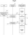
- FIG. 4 is a diagram showing the operation of the image forming apparatus 1 when the number of times a person has been detected reaches the specified number within a first period.
- FIG. 5 is a diagram showing the operation of the image forming apparatus 1 when the number of times a person has been detected falls short of the specified number within the first period.
- the controller 10 When the image forming apparatus 1 is powered on by the user, the controller 10 starts up the image forming apparatus 1 to operate it in the normal mode and launches the return determination program stored in the HDD 18 to start execution of the return determination processing shown in FIG. 3 .
- the controller 10 resets the value of a variable N indicated by a number-of-detections counter for use in counting the number of times the detection device 12 has detected a person to "0" (step S10).
- the controller 10 determines whether or not a predetermined second period has passed before the operation device 16 accepts an instruction (step S11).
- the controller 10 previously sets the second period at a predetermined default period (for example, five minutes).
- the controller 10 may set the second period in accordance with an instruction from an administrator or a user, the instruction indicating a period and having been accepted through the operation device 16 by the controller 10.
- the controller 10 determines that the second period has not passed (NO in step S11) and determines whether or not an instruction to transition to the power-saving mode has been accepted (step S12). In this case, the controller 10 determines that no instruction to transition has been accepted (NO in step S12) and goes back to the processing in step S11.
- the controller 10 determines that an instruction to transition to the power-saving mode has been accepted (YES in step S12) and starts time counting from the time of acceptance of the instruction to transition using a general time counting function (step S13). After the processing in step S13, the controller 10 allows the image forming apparatus 1 to transition from the normal mode to the power-saving mode (step S14) as shown in FIGS. 4 and 5 .
- the controller 10 determines whether or not a predetermined first period T1 has passed from the time of acceptance of the instruction to transition (step S15).
- the controller 10 previously sets the first period T1 at a predetermined default period (for example, ten seconds).
- the controller 10 may set the first period T1 in accordance with an instruction from an administrator or a user, the instruction indicating a period and having been accepted through the operation device 16 by the controller 10.
- the controller 10 determines whether or not the detection device 21 has detected any person existing within a predetermined range around the image forming apparatus 1 (step S16). In this case, the controller 10 determines that the detection device 21 has detected no person (NO in step S16) and goes back to the processing in step S15.
- the controller 10 determines that the first period T1 has not passed (NO in step S15), determines, as shown in FIGS. 4 and 5 , that the detection device 21 has detected any person (YES in step S16), and adds 1 to the value of the variable N indicated by the number-of-detections counter (step S17).
- the controller 10 determines whether or not the value of the variable N has reached a predetermined specified number (step S18).
- the controller 10 previously sets the specified number at a predetermined default number (in this case, two).
- the controller 10 may set the specified number in accordance with an instruction from an administrator or a user, the instruction indicating a number and having been accepted through the operation device 16 by the controller 10.
- the controller 10 determines that the value of the variable N has not reached the predetermined specified number (NO in step S18), keeps the image forming apparatus 1 in the power-saving mode, and goes back to the processing in step S15.
- the controller 10 determines that the first period T1 has not passed (NO in step S15), determines, as shown in FIG. 4 , that the detection device 21 has detected any person (YES in step S16), and adds 1 to the value of the variable N indicated by the number-of-detections counter (step S17).
- step S18 the controller 10 determines that the value of the variable N has reached the predetermined specified number (YES in step S18), and returns the image forming apparatus 1 from the power-saving mode to the normal mode (step S19) as shown in FIG. 4 . After the processing in step S19, the controller 10 goes back to the processing in step S10.
- the detection device 21 has then detected the user like the above case, and, thereafter, the first period T1 has passed before the detection device 21 further detects any person.
- the controller 10 determines that the first period T1 has passed (YES in step S15) and determines whether or not the detection device 21 has detected any person (step S20). In this case, the controller 10 determines that the detection device 21 has detected no person (NO in step S20) and repeats the processing in step S20.
- step S20 determines, as shown in FIG. 5 , that the detection device 21 has detected any person (YES in step S20) and returns the image forming apparatus 1 from the power-saving mode to the normal mode (step S19). After the processing in step S19, the controller 10 goes back to the processing in step S10.
- the controller 10 determines that the second period has passed (YES in step S11) and determines whether or not the detection device 21 has detected any person (step S20). In this case, the controller 10 determines that the detection device 21 has detected no person (NO in step S20) and repeats the processing in step S20.
- step S20 determines that the detection device 21 has detected any person (YES in step S20) and returns the image forming apparatus 1 from the power-saving mode to the normal mode (step S19). After the processing in step S19, the controller 10 goes back to the processing in step S10.
- the controller 10 when the image forming apparatus 1 is in the normal mode and, in this state, the controller 10 accepts through the operation device 16 an instruction to transition to the power-saving mode, the controller 10 allows the image forming apparatus 1 to transition from the normal mode to the power-saving mode.
- the controller 10 counts the number of times that the detection device 21 has detected a person within the first period from the time of acceptance of the instruction to transition. When the counted number of times reaches the specified number, the controller 10 returns the image forming apparatus 1 from the power-saving mode to the normal mode. When the counted number of times within the first period falls short of the specified number, the controller 10 keeps the image forming apparatus 1 in the power-saving mode.
- the image forming apparatus without use of a high-performance sensor, it can be prevented that, within the first period from the time of acceptance of the instruction to transition, the image forming apparatus undesirably returns to the normal mode.
- the determination of whether to return to the normal mode based on the counted number of times is not made. Therefore, even if a user having held down the power-saving key stays close to the image forming apparatus, other users can use the image forming apparatus. Therefore, an image forming apparatus low in cost and excellent in convenience and power-saving capability can be provided.
- the controller 10 sets the first period at a predetermined default period.
- the controller 10 sets the first period in accordance with an instruction accepted through the operation device 16 by the controller 10 and indicating a period.
- the first period can be set at an appropriate period without any instruction input by an administrator or a user or the administrator or the user can set the first period at a desired period. Therefore, the user's convenience can be further increased.
- the controller 10 when, after the first period passes from the time of acceptance of the instruction to transition, the detection device 21 first detects a person, the controller 10 returns the image forming apparatus 1 from the power-saving mode to the normal mode.
- the controller 10 sets the specified number at a predetermined default number.
- the controller 10 sets the specified number in accordance with an instruction accepted through the operation device 16 by the controller 10 and indicating a number.
- the specified number can be set at an appropriate number without any instruction input by an administrator or a user or the administrator or the user can set the specified number at a desired number. Therefore, the user's convenience can be further increased.
- the controller 10 when the image forming apparatus 1 is in the normal mode and, in this state, the second period has passed before the operation device 16 accepts an instruction, the controller 10 allows the image forming apparatus 1 to transition from the normal mode to the power-saving mode.
- the detection device 21 first detects a person, the controller 10 returns the image forming apparatus 1 from the power-saving mode to the normal mode.
- the return to the normal mode is made at the time when the detection device 21 first detects a person, rather than waiting until the number of times a person has been detected reaches the specified number. Therefore, when the transition to the power-saving mode has been made based on the passage of the second period, the return to the normal mode can be made with a more appropriate timing.
- the controller 10 sets the first period T1 at ten seconds
- the first period T1 is not particularly limited so long as it is a period of time it normally takes for the user having held down the power-saving key 16A to leave the predetermined range around the image forming apparatus 1.
- the controller 10 may set the first period T1 at 5 seconds, 30 seconds or the like.
- controller 10 sets the specified number at two
- the present invention is not limited to the above embodiment.
- the specified number is not particularly limited so long as it is at least two.
- the controller 10 may set the specified number at three, four or so on.
- the present invention is not limited to the above embodiment.
- the image forming device 12 and so on may form an image, not only on a recording paper sheet but on other types of recording media.
- An example of the other types of recording media is an OHP (overhead projector) sheet.
- the present invention is not limited to the structure and configuration of the above embodiment and can be modified in various ways.
- a multicolor multifunction peripheral is used as an image forming apparatus, it is merely illustrative and other types of image forming apparatuses, such as a black-and-white multifunction peripheral, a copier or a facsimile machine, may be used.
- FIGS. 1 to 5 The structure, configuration, and processing of the above embodiment described with reference to FIGS. 1 to 5 are merely illustrative of the present invention and are not intended to limit the present invention to them.
Landscapes
- Engineering & Computer Science (AREA)
- Multimedia (AREA)
- Signal Processing (AREA)
- General Physics & Mathematics (AREA)
- Physics & Mathematics (AREA)
- Biomedical Technology (AREA)
- General Health & Medical Sciences (AREA)
- Health & Medical Sciences (AREA)
- Microelectronics & Electronic Packaging (AREA)
- Theoretical Computer Science (AREA)
- General Engineering & Computer Science (AREA)
- Computer Security & Cryptography (AREA)
- Human Computer Interaction (AREA)
- Facsimiles In General (AREA)
- Control Or Security For Electrophotography (AREA)
- Accessory Devices And Overall Control Thereof (AREA)
Abstract
An image forming apparatus (1) includes an image forming device (12), an operation device (16), a detection device (21), and a control device (100) functioning as a controller (10). When accepting through the operation device (16) an instruction to transition to a second power state, the controller (10) allows the image forming apparatus (1) to transition from a first power state to the second power state. The controller (10) counts a number of times that the detection device (21) has detected a person existing within a predetermined range within a predetermined first period from a time of acceptance of the instruction to transition. When the counted number of times reaches a predetermined number of at least two, the controller (10) returns the image forming apparatus (1) from the second power state to the first power state. When the counted number of times falls short of the predetermined number, the controller (10) keeps the image forming apparatus (1) in the second power state.
Description
- The present invention relates to image forming apparatuses and particularly relates to a technique for determining the timing of return from a power-saving mode to a normal mode.
- There is known an image forming apparatus that returns from a power-saving mode to a normal mode when a human detection sensor has detected a person. In such an image forming apparatus, when, after the user holds down a power-saving key to make the transition of the image forming apparatus to the power-saving mode, the user having held down the power-saving key leaves the image forming apparatus, the human detection sensor may detect the user. In this case, even just after transition to the power-saving mode by the user's hold-down of the power-saving key, the image forming apparatus undesirably returns to the normal mode.
- As a solution to this problem, there is known a technique in which, generally, when the apparatus transitions to the power-saving mode by the hold-down of the power-saving key, the return to the normal mode based on the detection of a person by the human detection sensor is suspended until the human detection sensor first detects a person and then no longer detect the person. As another solution, it is possible to propose a technique of determining whether to return to the normal mode using a high-performance human detection sensor capable of detecting user's approach to and leaving from the image forming apparatus.
- A technique improved over the aforementioned techniques is proposed as one aspect of the present invention.
- An image forming apparatus according to an aspect of the present invention includes an image forming device, an operation device, a detection device, and a control device. The image forming device forms an image on a recording paper sheet. The operation device accepts an input of a user's instruction. The detection device detects a person existing within a predetermined range. The control device includes a processor and functions as a controller through the processor executing a control program. When the image forming apparatus is in a predetermined first power state and, in this state, the controller accepts through the operation device an instruction to transition to a second power state smaller in power consumption than in the first power state, the controller allows the image forming apparatus to transition from the first power state to the second power state. The controller counts a number of times that the detection device has detected a person within a predetermined first period from a time of acceptance of the instruction to transition. When the counted number of times reaches a predetermined number of at least two, the controller returns the image forming apparatus from the second power state to the first power state. When the counted number of times falls short of the predetermined number, the controller keeps the image forming apparatus in the second power state.
-
-
FIG. 1 is a frontal cross-sectional view showing the structure of an image forming apparatus according to one embodiment of the present invention. -
FIG. 2 is a block diagram showing the configuration of the image forming apparatus. -
FIG. 3 is a flowchart showing return determination processing. -
FIG. 4 is a diagram showing the operation of the image forming apparatus when the number of times a person has been detected reaches a specified number within a first period. -
FIG. 5 is a diagram showing the operation of the image forming apparatus when the number of times a person has been detected falls short of the specified number within the first period. - Hereinafter, a description will be given of an image forming apparatus according to one embodiment of the present invention with reference to the drawings.
FIG. 1 is a frontal cross-sectional view showing the structure of theimage forming apparatus 1 according to the one embodiment of the present invention.FIG. 2 is a block diagram showing the configuration of theimage forming apparatus 1. - Referring to
FIG. 1 , theimage forming apparatus 1 is a multifunction peripheral having multiple functions, such as a copy function, a transmission function, a print function, and a facsimile function. A housing of theimage forming apparatus 1 contains animage reading device 11, animage forming device 12, a fixingdevice 13, asheet feed device 14, and so on. - The
image reading device 11 is an ADF (auto document feeder) including: adocument conveyance device 6 that conveys an original document placed on a document loading table; and a scanner that optically reading an original document conveyed by thedocument conveyance device 6 or an original document placed on aplaten glass 7. Theimage reading device 11 irradiates the original document with light from a lighting part, receives light reflected from the original document on a CCD (charge-coupled device) sensor to read an image of the original document, and thus generates image data representing the image of the original document. - The
image forming device 12 includes, for each of different color toners, a photosensitive drum, a charging device, an exposure device, a developing device, and a transfer device. Theimage forming device 12 forms an image formed of a toner image on a recording paper sheet P being conveyed along a conveyance path T by aconveyance device 17, based on the image data generated by theimage reading device 11, image data input through acommunication device 23 or other type of image data. - The
fixing device 13 applies heat and pressure to the recording paper sheet P having the toner image formed thereon by theimage forming device 12, thus fixing the toner image on the recording paper sheet P. The recording paper sheet P having the toner image fixed thereon is discharged to asheet output tray 8. - The
sheet feed device 14 includes a manual feed tray and a plurality of sheet feed cassettes. Thesheet feed device 14 pulls out recording paper sheets P contained in one of the plurality of sheet feed cassettes or recording paper sheets placed on the manual feed tray, sheet by sheet, with a pick-up roller and feeds forward the pulled-out recording paper sheet to the conveyance path T. - Referring to
FIG. 2 , theimage forming apparatus 1 includes acontrol device 100. Thecontrol device 100 includes a processor, a RAM (random access memory), and a ROM (read only memory). The processor is, for example, a CPU (central processing unit), an MPU (micro processing unit) or an ASIC (application specific integrated circuit). - The
control device 100 is electrically connected to thedocument conveyance device 6, theimage reading device 11, theimage forming device 12, thefixing device 13, thesheet feed device 14, adisplay device 15, anoperation device 16, theconveyance device 17, an HDD (hard disk drive) 18, animage processing device 19, animage memory 20, adetection device 21, afacsimile communication device 22, acommunication device 23, and so on. - When each of various types of control programs stored in the ROM built in the
control device 100 or the HDD 18 is executed by the above processor, thecontrol device 100 functions as acontroller 10. Thecontroller 10 governs the overall operation control of theimage forming apparatus 1. More specifically, thecontroller 10 controls the operations of the devices constituting theimage forming apparatus 1 and communications with a PC (personal computer) 24 and other external devices connected via a network. - Alternatively, the
controller 10 may not be implemented by the operation of the processor in accordance with the above control programs, but may instead be configured operatively by a logic circuit, or may be configured implementably by two or more control devices - The
display device 15 is display equipment composed of a liquid crystal display or an organic EL (an organic light-emitting diode) display. Thedisplay device 15 displays various screens related to various functions executable by theimage forming apparatus 1. - The
operation device 16 includes a plurality of hard keys, including a power-savingkey 16A for use in inputting an instruction to transition from a normal mode to a power-saving mode. Theoperation device 16 further includes atouch panel 16B superposed on thedisplay device 15. Theoperation device 16 accepts an input of a user's instruction related to each of the functions executable by theimage forming apparatus 1. - The
conveyance device 17 includes: rollers includingconveyance roller pairs 17A and anejection roller pair 17B; and a conveyance motor connected to theconveyance roller pairs 17A and theejection roller pair 17B. Thecontroller 10 drives the conveyance motor to rotate theconveyance roller pairs 17A and theejection roller pair 17B, thus allowing the rollers to convey the recording paper sheet P, which has been fed by thesheet feed device 14, toward theimage forming device 12 and the sheet output tray 8 along the conveyance path T. - The
HDD 18 stores various types of data, including image data generated by theimage reading device 11 and various control programs for implementing the operations of theimage forming apparatus 1. In this embodiment, theHDD 18 stores a return determination program for use in executing return determination processing to be described hereinafter. - The
image processing device 19 performs, as necessary, image processing of image data generated by theimage reading device 11. Theimage memory 20 includes a region that temporarily stores image data generated by theimage reading device 11. - The
detection device 21 is provided on the front side of theimage forming apparatus 1. Thedetection device 21 is a human detection sensor that detects a person existing within a predetermined range around theimage forming apparatus 1. Thedetection device 21 may be any one generally used as a detection device and is not particularly limited, and, for example, an infrared sensor may be used. - The
facsimile communication device 22 performs connection to a public line and transfers image data to and from other facsimile devices via the public line. Thecommunication device 23 includes a communication module, such as a LAN (local area network) board. Thecontroller 10 performs data communications through thecommunication device 23 with external devices, such as the PC 24, connected thereto via the network. - Each of the devices constituting the
image forming apparatus 1 is connected to a power supply. When theimage forming apparatus 1 is powered on by the user, electric power is supplied from the power supply to each of the devices of theimage forming apparatus 1. - The
controller 10 allows theimage forming apparatus 1 to operate in either a normal mode or a power-saving mode. In the normal mode, theimage forming apparatus 1 operates in a predetermined first power state. The first power state refers to a state where power is suppled well to each of the devices of theimage forming apparatus 1 to enable immediate execution of various functions of theimage forming apparatus 1. - In the power-saving mode, the
image forming apparatus 1 operates in a second power state smaller in power consumption than in the first power state. The second power state refers to a state where power supply to each of the devices of theimage forming apparatus 1 is reduced or shut off and only a bare minimum of power to operate theimage forming apparatus 1 is supplied to each of the devices of theimage forming apparatus 1. In the power-saving mode, for example, a fixing roller of the fixingdevice 13 is held at low temperature and the screen of thedisplay device 15 is hidden. - In this embodiment, the
controller 10 operates in accordance with the above-described return determination program to execute return determination processing, wherein when theimage forming apparatus 1 is in the normal mode and, in this state, thecontroller 10 accepts through theoperation device 16 an instruction to transition to the power-saving mode, thecontroller 10 allows theimage forming apparatus 1 to transition from the normal mode to the power-saving mode and counts the number of times that thedetection device 21 has detected a person within a predetermined period from the time of acceptance of the instruction to transition, wherein when the counted number of times reaches a specified number, thecontroller 10 returns theimage forming apparatus 1 from the power-saving mode to the normal mode, and wherein when the counted number of times falls short of the specified number, thecontroller 10 keeps theimage forming apparatus 1 in the power-saving mode. - Hereinafter, a description will be given of the operation of the
image forming apparatus 1 during execution of the return determination processing with reference toFIGS. 3 to 5 and so on.FIG. 3 is a flowchart showing the return determination processing.FIG. 4 is a diagram showing the operation of theimage forming apparatus 1 when the number of times a person has been detected reaches the specified number within a first period.FIG. 5 is a diagram showing the operation of theimage forming apparatus 1 when the number of times a person has been detected falls short of the specified number within the first period. - When the
image forming apparatus 1 is powered on by the user, thecontroller 10 starts up theimage forming apparatus 1 to operate it in the normal mode and launches the return determination program stored in theHDD 18 to start execution of the return determination processing shown inFIG. 3 . When starting the execution of the return determination processing, thecontroller 10 resets the value of a variable N indicated by a number-of-detections counter for use in counting the number of times thedetection device 12 has detected a person to "0" (step S10). - After the processing in step S10, the
controller 10 determines whether or not a predetermined second period has passed before theoperation device 16 accepts an instruction (step S11). Here, thecontroller 10 previously sets the second period at a predetermined default period (for example, five minutes). Alternatively, thecontroller 10 may set the second period in accordance with an instruction from an administrator or a user, the instruction indicating a period and having been accepted through theoperation device 16 by thecontroller 10. - In this case, the
controller 10 determines that the second period has not passed (NO in step S11) and determines whether or not an instruction to transition to the power-saving mode has been accepted (step S12). In this case, thecontroller 10 determines that no instruction to transition has been accepted (NO in step S12) and goes back to the processing in step S11. - When the user holds down the power-saving key 16A while the
image forming apparatus 1 is in the normal mode, thecontroller 10 determines that an instruction to transition to the power-saving mode has been accepted (YES in step S12) and starts time counting from the time of acceptance of the instruction to transition using a general time counting function (step S13). After the processing in step S13, thecontroller 10 allows theimage forming apparatus 1 to transition from the normal mode to the power-saving mode (step S14) as shown inFIGS. 4 and5 . - After the processing in step S14, the
controller 10 determines whether or not a predetermined first period T1 has passed from the time of acceptance of the instruction to transition (step S15). Here, thecontroller 10 previously sets the first period T1 at a predetermined default period (for example, ten seconds). Alternatively, thecontroller 10 may set the first period T1 in accordance with an instruction from an administrator or a user, the instruction indicating a period and having been accepted through theoperation device 16 by thecontroller 10. - When determining that the first period T1 has not passed (NO in step S15), the
controller 10 determines whether or not thedetection device 21 has detected any person existing within a predetermined range around the image forming apparatus 1 (step S16). In this case, thecontroller 10 determines that thedetection device 21 has detected no person (NO in step S16) and goes back to the processing in step S15. - Here, assume that before the first period T1 passes, the user having held down the power-saving key 16A has left the
image forming apparatus 1 and thedetection device 21 has detected the user. Thecontroller 10 determines that the first period T1 has not passed (NO in step S15), determines, as shown inFIGS. 4 and5 , that thedetection device 21 has detected any person (YES in step S16), and adds 1 to the value of the variable N indicated by the number-of-detections counter (step S17). - After the processing in step S17, the
controller 10 determines whether or not the value of the variable N has reached a predetermined specified number (step S18). Here, thecontroller 10 previously sets the specified number at a predetermined default number (in this case, two). Alternatively, thecontroller 10 may set the specified number in accordance with an instruction from an administrator or a user, the instruction indicating a number and having been accepted through theoperation device 16 by thecontroller 10. - In this case, since the value of the variable N is " 1", the
controller 10 determines that the value of the variable N has not reached the predetermined specified number (NO in step S18), keeps theimage forming apparatus 1 in the power-saving mode, and goes back to the processing in step S15. - Here, assume that before the first period T1 passes, another user different from the user having held down the power-saving key 16A has approached the
image forming apparatus 1 to use theimage forming apparatus 1 and thedetection device 21 has detected the other user. Thecontroller 10 determines that the first period T1 has not passed (NO in step S15), determines, as shown inFIG. 4 , that thedetection device 21 has detected any person (YES in step S16), and adds 1 to the value of the variable N indicated by the number-of-detections counter (step S17). - In this case, since the value of the variable N becomes "2", the
controller 10 determines that the value of the variable N has reached the predetermined specified number (YES in step S18), and returns theimage forming apparatus 1 from the power-saving mode to the normal mode (step S19) as shown inFIG. 4 . After the processing in step S19, thecontroller 10 goes back to the processing in step S10. - Here, assume that a user having held down the power-saving key 16A has left the
image forming apparatus 1, thedetection device 21 has then detected the user like the above case, and, thereafter, the first period T1 has passed before thedetection device 21 further detects any person. - In this case, the
controller 10 determines that the first period T1 has passed (YES in step S15) and determines whether or not thedetection device 21 has detected any person (step S20). In this case, thecontroller 10 determines that thedetection device 21 has detected no person (NO in step S20) and repeats the processing in step S20. - Here, assume that another user different from the user having held down the power-saving key 16A has approached the
image forming apparatus 1 to use theimage forming apparatus 1 and thedetection device 21 has detected the other user. Thecontroller 10 determines, as shown inFIG. 5 , that thedetection device 21 has detected any person (YES in step S20) and returns theimage forming apparatus 1 from the power-saving mode to the normal mode (step S19). After the processing in step S19, thecontroller 10 goes back to the processing in step S10. - Here, assume that the
image forming apparatus 1 is in the normal mode and, in this state, the second period has passed before theoperation device 16 accepts an instruction. Thecontroller 10 determines that the second period has passed (YES in step S11) and determines whether or not thedetection device 21 has detected any person (step S20). In this case, thecontroller 10 determines that thedetection device 21 has detected no person (NO in step S20) and repeats the processing in step S20. - Here, assume that, for example, another user different from the user having powered on the
image forming apparatus 1 has approached theimage forming apparatus 1 to use theimage forming apparatus 1 and thedetection device 21 has detected the other user. Thecontroller 10 determines that thedetection device 21 has detected any person (YES in step S20) and returns theimage forming apparatus 1 from the power-saving mode to the normal mode (step S19). After the processing in step S19, thecontroller 10 goes back to the processing in step S10. - In the general technique described previously, when a user having held down the power-saving key stays close to the image forming apparatus for a long time, the return to the normal mode is suspended until the user leaves the image forming apparatus. Therefore, the convenience of other users who want to use the image forming apparatus may be impaired. In addition, when the image forming apparatus is provided with such a high-performance human detection sensor as described previously, a problem of cost increase arises.
- Unlike this, in the above embodiment, when the
image forming apparatus 1 is in the normal mode and, in this state, thecontroller 10 accepts through theoperation device 16 an instruction to transition to the power-saving mode, thecontroller 10 allows theimage forming apparatus 1 to transition from the normal mode to the power-saving mode. Thecontroller 10 counts the number of times that thedetection device 21 has detected a person within the first period from the time of acceptance of the instruction to transition. When the counted number of times reaches the specified number, thecontroller 10 returns theimage forming apparatus 1 from the power-saving mode to the normal mode. When the counted number of times within the first period falls short of the specified number, thecontroller 10 keeps theimage forming apparatus 1 in the power-saving mode. - Thus, without use of a high-performance sensor, it can be prevented that, within the first period from the time of acceptance of the instruction to transition, the image forming apparatus undesirably returns to the normal mode. In addition, after the first period passes, the determination of whether to return to the normal mode based on the counted number of times is not made. Therefore, even if a user having held down the power-saving key stays close to the image forming apparatus, other users can use the image forming apparatus. Therefore, an image forming apparatus low in cost and excellent in convenience and power-saving capability can be provided.
- Furthermore, in the above embodiment, the
controller 10 sets the first period at a predetermined default period. Alternatively, thecontroller 10 sets the first period in accordance with an instruction accepted through theoperation device 16 by thecontroller 10 and indicating a period. - Thus, the first period can be set at an appropriate period without any instruction input by an administrator or a user or the administrator or the user can set the first period at a desired period. Therefore, the user's convenience can be further increased.
- In addition, in the above embodiment, when, after the first period passes from the time of acceptance of the instruction to transition, the
detection device 21 first detects a person, thecontroller 10 returns theimage forming apparatus 1 from the power-saving mode to the normal mode. - Thus, even if, after the first period passes, a user having held down the power-saving key stays close to the image forming apparatus, other users can certainly use the image forming apparatus. Therefore, the user's convenience can be further increased.
- Furthermore, in the above embodiment, the
controller 10 sets the specified number at a predetermined default number. Alternatively, thecontroller 10 sets the specified number in accordance with an instruction accepted through theoperation device 16 by thecontroller 10 and indicating a number. - Thus, the specified number can be set at an appropriate number without any instruction input by an administrator or a user or the administrator or the user can set the specified number at a desired number. Therefore, the user's convenience can be further increased.
- In addition, in the above embodiment, when the
image forming apparatus 1 is in the normal mode and, in this state, the second period has passed before theoperation device 16 accepts an instruction, thecontroller 10 allows theimage forming apparatus 1 to transition from the normal mode to the power-saving mode. When, after the transition to the power-saving mode based on the passage of the second period, thedetection device 21 first detects a person, thecontroller 10 returns theimage forming apparatus 1 from the power-saving mode to the normal mode. - When, like the above case, there is no possibility of the
detection device 21 detecting the user having held down the power-saving key 16A, the return to the normal mode is made at the time when thedetection device 21 first detects a person, rather than waiting until the number of times a person has been detected reaches the specified number. Therefore, when the transition to the power-saving mode has been made based on the passage of the second period, the return to the normal mode can be made with a more appropriate timing. - Although in the above embodiment the
controller 10 sets the first period T1 at ten seconds, the present invention is not limited to the above embodiment. The first period T1 is not particularly limited so long as it is a period of time it normally takes for the user having held down the power-saving key 16A to leave the predetermined range around theimage forming apparatus 1. For example, thecontroller 10 may set the first period T1 at 5 seconds, 30 seconds or the like. - Although in the above embodiment the
controller 10 sets the specified number at two, the present invention is not limited to the above embodiment. The specified number is not particularly limited so long as it is at least two. For example, thecontroller 10 may set the specified number at three, four or so on. - Although in the above embodiment the
image forming device 12 and so on form an image on a recording paper sheet P, the present invention is not limited to the above embodiment. Theimage forming device 12 and so on may form an image, not only on a recording paper sheet but on other types of recording media. An example of the other types of recording media is an OHP (overhead projector) sheet. - The present invention is not limited to the structure and configuration of the above embodiment and can be modified in various ways. Although in the above embodiment a multicolor multifunction peripheral is used as an image forming apparatus, it is merely illustrative and other types of image forming apparatuses, such as a black-and-white multifunction peripheral, a copier or a facsimile machine, may be used.
- The structure, configuration, and processing of the above embodiment described with reference to
FIGS. 1 to 5 are merely illustrative of the present invention and are not intended to limit the present invention to them.
Claims (6)
- An image forming apparatus (1) comprising:an image forming device (12) that forms an image on a recording paper sheet;an operation device (16) that accepts an input of a user's instruction;a detection device (21) that detects a person existing within a predetermined range; anda control device (100) that includes a processor and functions as a controller (10) through the processor executing a control program, wherein when the image forming apparatus (1) is in a predetermined first power state and, in this state, the controller (10) accepts through the operation device (16) an instruction to transition to a second power state smaller in power consumption than in the first power state, the controller (10) allows the image forming apparatus (1) to transition from the first power state to the second power state,wherein the controller (10) counts a number of times that the detection device (21) has detected a person within a predetermined first period from a time of acceptance of the instruction to transition,when the counted number of times reaches a predetermined number of at least two, the controller (10) returns the image forming apparatus (1) from the second power state to the first power state, andwhen the counted number of times falls short of the predetermined number, the controller (10) keeps the image forming apparatus (1) in the second power state.
- The image forming apparatus (1) according to claim 1, wherein the controller (10) sets the first period at a predetermined default period or sets the first period in accordance with an instruction accepted through the operation device (16) by the controller (10) and indicating a period.
- The image forming apparatus (1) according to claim 1, wherein when, after the first period passes from the time of acceptance of the instruction to transition, the detection device (21) first detects a person, the controller (10) returns the image forming apparatus (1) from the second power state to the first power state.
- The image forming apparatus (1) according to claim 1, wherein the controller (10) sets the predetermined number at a predetermined default number or sets the predetermined number in accordance with an instruction accepted through the operation device (16) by the controller (10) and indicating a number.
- The image forming apparatus (1) according to claim 1, whereinwhen the image forming apparatus (1) is in the first power state and, in this state, a predetermined second period passes before the operation device (16) accepts the instruction to transition, the controller (10) allows the image forming apparatus (1) to transition from the first power state to the second power state, andwhen, after the controller (10) allows the image forming apparatus (1) to transition to the second power state based on passage of the second period, the detection device (21) first detects a person, the controller (10) returns the image forming apparatus (1) from the second power state to the first power state.
- The image forming apparatus (1) according to claim 1, wherein the controller (10) sets as the first period a period of time it normally takes for the user having input the instruction to transition to the operation device (16) to leave the predetermined range.
Applications Claiming Priority (1)
| Application Number | Priority Date | Filing Date | Title |
|---|---|---|---|
| JP2023204907A JP2025089928A (en) | 2023-12-04 | 2023-12-04 | Image forming device |
Publications (1)
| Publication Number | Publication Date |
|---|---|
| EP4567519A1 true EP4567519A1 (en) | 2025-06-11 |
Family
ID=93651530
Family Applications (1)
| Application Number | Title | Priority Date | Filing Date |
|---|---|---|---|
| EP24215008.4A Pending EP4567519A1 (en) | 2023-12-04 | 2024-11-25 | Image forming apparatus capable of returning from second power state to first power state according to number of times person has been detected within predetermined period |
Country Status (3)
| Country | Link |
|---|---|
| US (1) | US20250184438A1 (en) |
| EP (1) | EP4567519A1 (en) |
| JP (1) | JP2025089928A (en) |
Citations (4)
| Publication number | Priority date | Publication date | Assignee | Title |
|---|---|---|---|---|
| US20130073887A1 (en) * | 2011-09-15 | 2013-03-21 | Fuji Xerox Co., Ltd. | Power-supply control device, image processing apparatus, power-supply control method, and computer-readable medium |
| JP2016034735A (en) * | 2014-08-04 | 2016-03-17 | キヤノン株式会社 | Image forming apparatus, image forming apparatus control method, and program |
| US20180032013A1 (en) * | 2016-07-29 | 2018-02-01 | Canon Kabushiki Kaisha | Information processing apparatus, control method thereof, and storage medium |
| US20210227088A1 (en) * | 2020-01-22 | 2021-07-22 | Toshiba Tec Kabushiki Kaisha | Image forming apparatus |
-
2023
- 2023-12-04 JP JP2023204907A patent/JP2025089928A/en active Pending
-
2024
- 2024-11-25 EP EP24215008.4A patent/EP4567519A1/en active Pending
- 2024-12-02 US US18/965,598 patent/US20250184438A1/en active Pending
Patent Citations (4)
| Publication number | Priority date | Publication date | Assignee | Title |
|---|---|---|---|---|
| US20130073887A1 (en) * | 2011-09-15 | 2013-03-21 | Fuji Xerox Co., Ltd. | Power-supply control device, image processing apparatus, power-supply control method, and computer-readable medium |
| JP2016034735A (en) * | 2014-08-04 | 2016-03-17 | キヤノン株式会社 | Image forming apparatus, image forming apparatus control method, and program |
| US20180032013A1 (en) * | 2016-07-29 | 2018-02-01 | Canon Kabushiki Kaisha | Information processing apparatus, control method thereof, and storage medium |
| US20210227088A1 (en) * | 2020-01-22 | 2021-07-22 | Toshiba Tec Kabushiki Kaisha | Image forming apparatus |
Also Published As
| Publication number | Publication date |
|---|---|
| US20250184438A1 (en) | 2025-06-05 |
| JP2025089928A (en) | 2025-06-16 |
Similar Documents
| Publication | Publication Date | Title |
|---|---|---|
| JP4101074B2 (en) | Image forming apparatus | |
| CN104125361B (en) | Image processing system | |
| US10999463B2 (en) | Image forming apparatus executing processing for wake-up from power saving state according to direction of eye gaze detected by eye-gaze sensor | |
| JP6784268B2 (en) | Image forming device | |
| CN111131649A (en) | Image reading apparatus for reading original document and control method thereof | |
| JP5991341B2 (en) | Image forming apparatus, control method, and control program | |
| US9212016B2 (en) | Image forming apparatus automatically setting noise reduction | |
| JP5069768B2 (en) | Operating device and electronic device | |
| US20250184438A1 (en) | Image forming apparatus capable of returning from second power state to first power state according to number of times person has been detected within predetermined period | |
| US11765287B2 (en) | Information processing apparatus capable of allowing display device to display combinations of setting values satisfying predetermined condition | |
| CN111787175B (en) | Information processing apparatus | |
| JP6337817B2 (en) | Image forming apparatus and document reading apparatus | |
| US20170103289A1 (en) | Printing apparatus, control method of printing apparatus, and storage medium | |
| US8755697B2 (en) | Image forming apparatus | |
| US20160295049A1 (en) | Image forming apparatus | |
| US20240012356A1 (en) | Image forming apparatus | |
| JP6418171B2 (en) | Image forming apparatus | |
| JP6537888B2 (en) | Image processing device | |
| US10999459B2 (en) | Image reading device and image forming apparatus that perform notification processing for notifying user that special original document to be read preferably at high resolution has been detected from among original documents read at low resolution | |
| JP2025024267A (en) | Image forming device | |
| JP6358147B2 (en) | Image forming apparatus | |
| JP6354637B2 (en) | Image forming apparatus | |
| JP6470014B2 (en) | Image forming apparatus | |
| JP6206356B2 (en) | Image forming apparatus | |
| JP2021116166A (en) | Paper feed device, image forming device, and image reading device |
Legal Events
| Date | Code | Title | Description |
|---|---|---|---|
| PUAI | Public reference made under article 153(3) epc to a published international application that has entered the european phase |
Free format text: ORIGINAL CODE: 0009012 |
|
| STAA | Information on the status of an ep patent application or granted ep patent |
Free format text: STATUS: THE APPLICATION HAS BEEN PUBLISHED |
|
| AK | Designated contracting states |
Kind code of ref document: A1 Designated state(s): AL AT BE BG CH CY CZ DE DK EE ES FI FR GB GR HR HU IE IS IT LI LT LU LV MC ME MK MT NL NO PL PT RO RS SE SI SK SM TR |
|
| STAA | Information on the status of an ep patent application or granted ep patent |
Free format text: STATUS: REQUEST FOR EXAMINATION WAS MADE |
|
| 17P | Request for examination filed |
Effective date: 20251120 |