EP4567448A1 - Battery management system and method, and battery pack comprising same - Google Patents
Battery management system and method, and battery pack comprising same Download PDFInfo
- Publication number
- EP4567448A1 EP4567448A1 EP23872841.4A EP23872841A EP4567448A1 EP 4567448 A1 EP4567448 A1 EP 4567448A1 EP 23872841 A EP23872841 A EP 23872841A EP 4567448 A1 EP4567448 A1 EP 4567448A1
- Authority
- EP
- European Patent Office
- Prior art keywords
- voltage
- battery
- cell
- negative electrode
- battery cell
- Prior art date
- Legal status (The legal status is an assumption and is not a legal conclusion. Google has not performed a legal analysis and makes no representation as to the accuracy of the status listed.)
- Pending
Links
Images



Classifications
-
- G—PHYSICS
- G01—MEASURING; TESTING
- G01R—MEASURING ELECTRIC VARIABLES; MEASURING MAGNETIC VARIABLES
- G01R31/00—Arrangements for testing electric properties; Arrangements for locating electric faults; Arrangements for electrical testing characterised by what is being tested not provided for elsewhere
- G01R31/36—Arrangements for testing, measuring or monitoring the electrical condition of accumulators or electric batteries, e.g. capacity or state of charge [SoC]
- G01R31/396—Acquisition or processing of data for testing or for monitoring individual cells or groups of cells within a battery
-
- G—PHYSICS
- G01—MEASURING; TESTING
- G01R—MEASURING ELECTRIC VARIABLES; MEASURING MAGNETIC VARIABLES
- G01R19/00—Arrangements for measuring currents or voltages or for indicating presence or sign thereof
- G01R19/10—Measuring sum, difference or ratio
-
- G—PHYSICS
- G01—MEASURING; TESTING
- G01R—MEASURING ELECTRIC VARIABLES; MEASURING MAGNETIC VARIABLES
- G01R31/00—Arrangements for testing electric properties; Arrangements for locating electric faults; Arrangements for electrical testing characterised by what is being tested not provided for elsewhere
- G01R31/36—Arrangements for testing, measuring or monitoring the electrical condition of accumulators or electric batteries, e.g. capacity or state of charge [SoC]
- G01R31/374—Arrangements for testing, measuring or monitoring the electrical condition of accumulators or electric batteries, e.g. capacity or state of charge [SoC] with means for correcting the measurement for temperature or ageing
-
- G—PHYSICS
- G01—MEASURING; TESTING
- G01R—MEASURING ELECTRIC VARIABLES; MEASURING MAGNETIC VARIABLES
- G01R31/00—Arrangements for testing electric properties; Arrangements for locating electric faults; Arrangements for electrical testing characterised by what is being tested not provided for elsewhere
- G01R31/36—Arrangements for testing, measuring or monitoring the electrical condition of accumulators or electric batteries, e.g. capacity or state of charge [SoC]
- G01R31/382—Arrangements for monitoring battery or accumulator variables, e.g. SoC
- G01R31/3835—Arrangements for monitoring battery or accumulator variables, e.g. SoC involving only voltage measurements
-
- G—PHYSICS
- G01—MEASURING; TESTING
- G01R—MEASURING ELECTRIC VARIABLES; MEASURING MAGNETIC VARIABLES
- G01R31/00—Arrangements for testing electric properties; Arrangements for locating electric faults; Arrangements for electrical testing characterised by what is being tested not provided for elsewhere
- G01R31/36—Arrangements for testing, measuring or monitoring the electrical condition of accumulators or electric batteries, e.g. capacity or state of charge [SoC]
- G01R31/392—Determining battery ageing or deterioration, e.g. state of health
-
- Y—GENERAL TAGGING OF NEW TECHNOLOGICAL DEVELOPMENTS; GENERAL TAGGING OF CROSS-SECTIONAL TECHNOLOGIES SPANNING OVER SEVERAL SECTIONS OF THE IPC; TECHNICAL SUBJECTS COVERED BY FORMER USPC CROSS-REFERENCE ART COLLECTIONS [XRACs] AND DIGESTS
- Y02—TECHNOLOGIES OR APPLICATIONS FOR MITIGATION OR ADAPTATION AGAINST CLIMATE CHANGE
- Y02E—REDUCTION OF GREENHOUSE GAS [GHG] EMISSIONS, RELATED TO ENERGY GENERATION, TRANSMISSION OR DISTRIBUTION
- Y02E60/00—Enabling technologies; Technologies with a potential or indirect contribution to GHG emissions mitigation
- Y02E60/10—Energy storage using batteries
Definitions
- the present invention relates to a system and method for managing a battery, and a battery pack including the system, and more particularly, to a system and method for managing a battery, capable of accurately measuring characteristics of a battery cell, and a battery pack including the system.
- Secondary batteries are used as a battery pack including a battery module in which a plurality of battery cells are connected to each other in series and/or parallel. States and operations of the battery pack are managed and controlled by a battery management system.
- the battery management system may measure electrical characteristics of the battery cells, and determine a state of the battery based on the measured characteristics. However, when the electrical characteristics of the battery cells are not accurately measured, the state of the battery may not be properly checked.
- Embodiments according to the present invention provide a system and method for managing a battery, capable of accurately measuring characteristics of a battery cell, and a battery pack including the system.
- a battery pack may include: a battery module including a battery cell provided in plurality; at least one reference cell including more electrodes than the battery cell; a battery management system that controls the battery cell and the reference cell, wherein the battery management system measures a first voltage of the battery cell, measures a second voltage of the reference cell, and determines a state of the battery module based on a deviation between the first voltage and the second voltage.
- each of the plurality of battery cells may include a first negative electrode and a first positive electrode
- the reference cell may include a second negative electrode, a second positive electrode, and a reference electrode
- the first voltage may be a first negative electrode voltage of the battery cell
- the second voltage may be a second negative electrode voltage corresponding to a difference in potential between the reference electrode and the second negative electrode of the reference cell.
- the battery management system may measure the first negative electrode voltage while charging the battery cell, and measure the second negative electrode voltage while charging the reference cell.
- the first voltage may be a first cell voltage corresponding to a difference in potential between the first positive electrode and the first negative electrode
- the second voltage may be a second cell voltage corresponding to a difference between a second positive electrode voltage and a second negative electrode voltage
- the second positive electrode voltage corresponds to a difference in potential between the reference electrode and the second positive electrode
- the second negative electrode voltage corresponds to a difference in potential between the reference electrode and the second negative electrode
- the battery management system may measure the first cell voltage while charging the battery cell, and measure the second cell voltage while charging the reference cell.
- the battery management system may estimate a state of health (SOH) of the battery module based on a deviation between the first voltage and the second voltage, and determine a state of the plurality of battery cells based on the estimated SOH.
- SOH state of health
- the battery management system may correct the first voltage based on a deviation between the first voltage and the second voltage, estimate a state of health (SOH) of the battery module based on the corrected first voltage, and determine a state of each of the plurality of battery cells based on the estimated SOH.
- SOH state of health
- a battery management system may include: a measuring part that measures a first voltage of a battery cell, which is provided in plurality and comprised in a battery module, and measures a second voltage of at least one reference cell which comprises more electrodes than the battery cell; and a controller that determines a state of each of the plurality of battery cells based on a deviation between the first voltage and the second voltage.
- the measuring part may measure the first voltage while charging the battery cell including a first negative electrode and a first positive electrode, and measure the second voltage while charging the reference cell comprising a second negative electrode, a second positive electrode, and a reference electrode.
- a battery management method may include: measuring a first voltage of a battery cell provided in plurality and included in a battery module; measuring a second voltage of at least one reference cell that includes more electrodes than the battery cell; and determining a state of each of the plurality of battery cells based on a deviation between the first voltage and the second voltage.
- the electrical characteristics (e.g., the negative electrode voltage and the cell voltage) of the battery cell may be accurately measured through the reference electrode included in the reference cell.
- the state of health of the battery cell may be accurately measured based on the at least one of the negative electrode voltage or the cell voltage.
- the cell balancing may be performed.
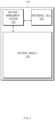
- FIG. 1 is a block diagram illustrating a battery pack according to the present invention.
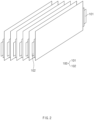
- FIG. 2 is a perspective view illustrating a battery cell included in a battery module illustrated in FIG. 1 .
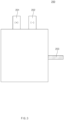
- FIG. 3 is a plan view illustrating a reference cell included in the battery pack illustrated in FIG. 1 .
- a battery pack 110 may include a reference cell 200, a battery module 130, and a battery management system 120.
- the battery module 130 may be provided in plurality, and each of the plurality of battery modules 130 may be provided in the form of a stack in which a plurality of battery cells 100 are stacked. As illustrated in FIG. 2 , each of the plurality of battery cells 100 may have a two-electrode structure including a first positive electrode 101 (or working electrode) and a first negative electrode 102 (or counter electrode).
- the reference cell 200 may be provided in at least one.
- the reference cell 200 may include more electrodes than the battery cell 100.
- the reference cell 200 may have a three-electrode structure including a second positive electrode 201, a second negative electrode 202, and a reference electrode 203.
- the reference electrode 203 may be used as a potential standard when measuring a relative value of an electrode potential. As current flows between the second positive electrode 201 and the second negative electrode 202, and the current hardly flows through the reference electrode 203, potential of the reference electrode 203 itself may not change. When measuring a second negative electrode voltage corresponding to a difference in potential between the reference electrode 203 and the second negative electrode 202 of the reference cell 200, the second negative electrode voltage may be precisely measured because the potential of the reference electrode 203 does not change. When measuring a second positive electrode voltage corresponding to a difference in potential between the reference electrode 203 and the second positive electrode 201 of the reference cell 200, the second positive electrode voltage may be precisely measured because the potential of the reference electrode 203 itself does not change.
- the battery management system 120 may include a plurality of terminals as interfaces that receive values obtained by measuring various parameters, a circuit connected to these terminals to perform processing of the received values, and the like.
- the battery management system 120 may monitor voltages, current, temperatures, or the like of each of the battery cell 100 included in the battery module 130 and the reference cell 200, to manage and control the battery cells so as to prevent overcharge, overdischarge, and the like, of the battery cell 100.
- FIG. 4 is a detailed block diagram illustrating the battery management system illustrated in FIG. 1 .
- the battery management system 120 may include a measuring part 121, a controller 122, and a storage part 123.
- the measuring part 121 may measure a first voltage of a battery cell (e.g., the battery cell 100 in FIG. 2 ), and measure a second voltage of a reference cell (e.g., the reference cell 200 in FIG. 3 ).
- the measuring part 121 may measure a first negative electrode voltage (or first voltage) of the battery cell while charging the battery cell.
- the measuring part 121 may measure the first negative electrode voltage corresponding to a difference between potential of a first negative electrode of the battery cell and reference potential (e.g., 0 V).
- the measuring part 121 may measure a second negative electrode voltage (or second voltage) corresponding to a difference in potential between a reference electrode and a second negative electrode of the reference cell while charging the reference cell.
- the measuring part 121 may measure the first negative electrode voltage in an opened state of the battery cell, and measure the second negative electrode voltage in an opened state of the reference cell.
- the controller 122 may be configured to calculate a deviation between the first negative electrode voltage of the battery cell and the second negative electrode voltage of the reference cell.
- the controller 122 may be communicatively connected to the measuring part 121 in a wired and/or wireless manner.
- the controller 122 may receive the first negative electrode voltage and the second negative electrode voltage from the measuring part 121, and calculate a voltage deviation between the received first negative electrode voltage and second negative electrode voltage.
- the controller 122 may accurately correct the first negative electrode voltage based on the voltage deviation between the first negative electrode voltage and the second negative electrode voltage.
- first positive electrode potential is changed in a state in which current flows between the first positive electrode and the first negative electrode of the battery cell, first negative electrode potential may be also changed, and thus the first negative electrode voltage is difficult to accurately measure.
- the second negative electrode voltage may be accurately measured compared to the battery cell. Accordingly, the controller 122 may accurately calculate the first negative electrode voltage by correcting the first negative electrode voltage based on the deviation between the first negative electrode voltage and the second negative electrode voltage, which are measured through the measuring part.
- the controller 122 may estimate a state of health (SOH) of each of the battery module and the battery pack, which include the battery cell, based on the corrected first negative electrode voltage.
- the controller 122 may estimate the SOH of each of the battery module and the battery pack based on data of a correlation between a pre-measured first negative electrode voltage and SOH.
- Data of a correlation between a corrected first negative electrode voltage and SOH may be pre-stored in the storage part 123.
- the data of the correlation between the corrected first negative electrode voltage and the SOH may be values obtained in advance through at least one pre-estimation.
- the data of the correlation between the corrected first negative electrode voltage and the SOH may be re-estimated at fixed intervals and periodically updated.
- the controller 122 may estimate a state of health (SOH) of each of the battery module and the battery pack, which include the battery cell, based on the voltage deviation between the first negative electrode voltage and the second negative electrode voltage.
- the controller 122 may estimate the SOH of each of the battery module and the battery pack based on data of a correlation between a voltage deviation between pre-measured negative electrode voltages and SOH.
- the data of a correlation between a voltage deviation between negative electrode voltages of the battery cell and the reference cell and SOH may be pre-stored in the storage part 123.
- the data of the correlation between the deviation between the negative electrode voltages of the battery cell and the reference cell and the SOH may be values obtained in advance through at least one pre-estimation.
- the data of the correlation between the deviation between negative electrode voltages of the battery cell and the reference cell and the SOH may be re-estimated at fixed intervals and periodically updated.
- the controller 122 may determine a state of each of the battery module and the battery pack, which include the battery cell, based on the estimated SOH.
- the controller 122 may predict a degree of degradation, replacement time, lifetime, and the like of the battery cell based on the estimated SOH.
- the controller 122 may select a battery cell, which is subject to balancing, based on the SOH of each of the plurality of battery cells. For example, the controller 122 may compare the respective SOHs of the plurality of battery cells, and select, as an object to be balanced, a battery cell of which the SOH goes beyond a threshold.
- the controller 122 may perform balancing on the battery cell selected as an object to be balanced. Accordingly, the battery module and the battery pack, which include the battery cell, may be safely managed.
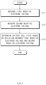
- FIG. 5 is a flowchart illustrating a battery management method according to a first embodiment of the present invention.
- the first negative electrode voltage of the battery cell may be decreased due to an electrochemical phenomenon in the battery cell.
- the battery cell is continuously charged in a state in which negative electrode potential of the battery cell is low (e.g., 0 V or less)
- a phenomenon in which the negative electrode is plated with a metal may occur to cause a reduction in lifetime of the battery cell.
- the present invention may measure the first negative electrode voltage of the battery cell so that the negative electrode potential of the battery cell is greater than the reference potential during charging of the battery cell.
- the measuring part may measure a second negative electrode voltage (or the second voltage) of a reference cell (e.g., the reference cell 200 in FIG. 3 ) while charging the reference cell.
- the second negative electrode voltage may correspond to a difference in potential between a reference electrode (e.g., the reference electrode 203 in FIG. 3 ) and a second negative electrode (e.g., the second negative electrode 202 in FIG. 3 ) of the reference cell.
- a controller may calculate a voltage deviation between the first negative electrode voltage of the battery cell and the second negative electrode voltage of the reference cell, correct the first negative electrode voltage based on the calculated voltage deviation, and estimate a state of health (SOH) of each of the battery module and the battery pack, which include the battery cell, based on the corrected first negative electrode voltage.
- SOH state of health
- the controller may calculate a voltage deviation between the first negative electrode voltage of the battery cell and the second negative electrode voltage of the reference cell, and estimate a state of health (SOH) of each of the battery module and the battery pack, which include the battery cell, based on the calculated voltage deviation.
- SOH state of health
- the controller may predict a degree of degradation, replacement time, lifetime, and the like of the battery cell based on the estimated SOH.
- the controller may control charging for the battery pack so that the first negative electrode voltage of the battery cell, which has been measured (or corrected) through the measuring part, is maintained at a fixed level or higher (or greater than the reference potential). Accordingly, the lifetime characteristics of the battery pack may be improved.
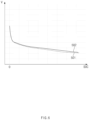
- FIG. 6 is a graph illustrating a negative electrode voltage according to a change in state of charge (SOC) of each of the battery cell and the reference cell according to the first embodiment of the present invention.
- a horizontal axis may indicate a SOC (or remaining capacity) of the battery
- a vertical axis may indicate a negative electrode voltage of each of the battery cell and the reference cell.
- the SOC being 0 may mean that the negative electrode voltage reaches a predetermined upper limit voltage, and the battery cell is in a fully discharged state
- the SOC gradually increasing from 0 may mean that as the negative electrode voltage gradually reaches a predetermined lower limit voltage, the battery cell approaches a fully charged state.
- a controller may generate a first negative electrode voltage profile 501 in which as a charged state of the battery cell increases (or an amount of lithium ions stored in the battery cell increases), the first negative electrode voltage gradually decreases.
- the controller may generate a second negative electrode voltage profile 502 in which as a charged state of the reference cell increases (or an amount of lithium ions stored in the reference cell increases), the second negative electrode voltage gradually decreases.
- the first negative electrode voltage profile 501 and the second negative electrode voltage profile 501 may be generated through charging experiments on the battery cell and the reference cell.
- the controller may calculate a voltage deviation between the first negative electrode voltage and the second negative electrode voltage, based on the first negative electrode voltage profile 501 and the second negative electrode voltage profile 502.
- the controller may estimate a state of health (SOH) of the battery cell based on the calculated voltage deviation.
- FIG. 7 is a flowchart illustrating a battery management method according to a second embodiment of the present invention.
- a measuring part may measure a first cell voltage (e.g., the first voltage) of a battery cell (e.g., the battery cell 100 in FIG. 2 ) while charging the battery cell.
- the first cell voltage may be a voltage corresponding to a difference in potential between a first positive electrode (e.g., the first positive electrode 101 in FIG. 2 ) and a first negative electrode (e.g., the first negative electrode 102 in FIG. 2 ) of the battery cell.
- a measuring part may measure a second cell voltage (or the second voltage) of a reference cell (e.g., the reference cell 200 in FIG. 3 ) while charging the reference cell.
- the second cell voltage may be a voltage corresponding to a difference between a second positive electrode voltage and a second negative electrode voltage of the reference cell.
- the second positive electrode voltage may be a voltage corresponding to a difference in potential between a reference electrode (e.g., the reference electrode 203 in FIG. 3 ) and a second positive electrode (e.g., the second positive electrode 201 in FIG. 3 ) of the reference cell.
- the second negative electrode voltage may be a voltage corresponding to a difference in potential between the reference electrode of the reference cell and a second negative electrode (e.g., the second negative electrode 202 in FIG. 3 ).
- a controller may calculate a voltage deviation between the first cell voltage of the battery cell and the second cell voltage of the reference cell, correct the first cell voltage based on the calculated voltage deviation, and estimate a state of health (SOH) of each of the battery module and the battery pack, which include the battery cell, based on the corrected first cell voltage.
- SOH state of health
- the controller may calculate a voltage deviation between the first cell voltage of the battery cell and the second cell voltage of the reference cell, and estimate a state of health (SOH) of each of the battery module and the battery pack, which include the battery cell, based on the calculated voltage deviation.
- SOH state of health
- the controller 122 may predict a degree of degradation, replacement time, lifetime, and the like of the battery cell based on the estimated SOH.
- FIG. 8 is a graph illustrating a negative electrode voltage according to a change in state of charge (SOC) of each of a battery cell and a reference cell according to the second embodiment of the present invention.
- a horizontal axis may indicate a SOC (or remaining capacity) of the battery
- a vertical axis may indicate a cell voltage of each of the battery cell and the reference cell.
- a controller may generate a first cell voltage profile 711 in which as a charged state of the battery cell increases (or an amount of lithium ions stored in the battery cell increases), the first cell voltage gradually increases.
- the controller may generate a second cell voltage profile 712 in which as a charged state of the reference cell increases (or an amount of lithium ions stored in the reference cell increases), the second cell voltage gradually increases.
- the first cell voltage profile 711 and the second cell voltage profile 712 may be generated through charging experiments on the battery cell and the reference cell.
- the controller may calculate a voltage deviation between the first cell voltage and the second cell voltage, based on the first cell voltage profile 711 and the second cell voltage profile 712.
- the controller may accurately measure a state of health (SOH) of the battery cell based on the calculated voltage deviation.
- SOH state of health
- the foregoing battery management system and battery management method are not limited to the embodiments described with reference to the drawings, respectively, and the respective structures described in the drawings may be applied in combination with each other.
- the battery management system according to the present invention may be employed in combination with the management method described with reference to FIG. 5 , or with the management method described with reference to FIG. 7 .
- the battery cell and the reference cell according to the present invention are described with examples of pouch type structures, but are not limited thereto.
- the battery cell and the reference cell may be applied to cylindrical type or prismatic type structures.
- the foregoing battery pack may be applied to various devices.
- the battery pack may be applied to transport means such as electric bikes, electric vehicles, or hybrid vehicles.
- the battery pack is not limited thereto, and may be applicable to various devices that may use a battery pack.
Landscapes
- Physics & Mathematics (AREA)
- General Physics & Mathematics (AREA)
- Secondary Cells (AREA)
- Charge And Discharge Circuits For Batteries Or The Like (AREA)
- Tests Of Electric Status Of Batteries (AREA)
Abstract
Description
- The present application claims the benefit of the priority of
Korean Patent Application No. 10-2022-0125848, filed on September 30, 2022 - The present invention relates to a system and method for managing a battery, and a battery pack including the system, and more particularly, to a system and method for managing a battery, capable of accurately measuring characteristics of a battery cell, and a battery pack including the system.
- Recently, as a demand for portable electronic products such as notebook computers, video cameras, and mobile phones rapidly increases, and development for electric vehicles, accumulators for energy storage, robots, and satellites is regularized, much research is carried out on secondary batteries used as driving power sources thereof.
- Secondary batteries are used as a battery pack including a battery module in which a plurality of battery cells are connected to each other in series and/or parallel. States and operations of the battery pack are managed and controlled by a battery management system.
- The battery management system may measure electrical characteristics of the battery cells, and determine a state of the battery based on the measured characteristics. However, when the electrical characteristics of the battery cells are not accurately measured, the state of the battery may not be properly checked.
- Embodiments according to the present invention provide a system and method for managing a battery, capable of accurately measuring characteristics of a battery cell, and a battery pack including the system.
- The technical problems of the present invention are not limited to the aforementioned technical problems, and the other technical problems not mentioned above could be clearly understood by those skilled in the art from the disclosure below.
- A battery pack according to an embodiment of the present invention may include: a battery module including a battery cell provided in plurality; at least one reference cell including more electrodes than the battery cell; a battery management system that controls the battery cell and the reference cell, wherein the battery management system measures a first voltage of the battery cell, measures a second voltage of the reference cell, and determines a state of the battery module based on a deviation between the first voltage and the second voltage.
- According to an embodiment, each of the plurality of battery cells may include a first negative electrode and a first positive electrode, and the reference cell may include a second negative electrode, a second positive electrode, and a reference electrode.
- According to an embodiment, the first voltage may be a first negative electrode voltage of the battery cell, and the second voltage may be a second negative electrode voltage corresponding to a difference in potential between the reference electrode and the second negative electrode of the reference cell.
- According to an embodiment, the battery management system may measure the first negative electrode voltage while charging the battery cell, and measure the second negative electrode voltage while charging the reference cell.
- According to an embodiment, the first voltage may be a first cell voltage corresponding to a difference in potential between the first positive electrode and the first negative electrode, and the second voltage may be a second cell voltage corresponding to a difference between a second positive electrode voltage and a second negative electrode voltage, wherein the second positive electrode voltage corresponds to a difference in potential between the reference electrode and the second positive electrode, and the second negative electrode voltage corresponds to a difference in potential between the reference electrode and the second negative electrode.
- According to an embodiment, the battery management system may measure the first cell voltage while charging the battery cell, and measure the second cell voltage while charging the reference cell.
- According to an embodiment, the battery management system may estimate a state of health (SOH) of the battery module based on a deviation between the first voltage and the second voltage, and determine a state of the plurality of battery cells based on the estimated SOH.
- According to an embodiment, the battery management system may correct the first voltage based on a deviation between the first voltage and the second voltage, estimate a state of health (SOH) of the battery module based on the corrected first voltage, and determine a state of each of the plurality of battery cells based on the estimated SOH.
- A battery management system according to an embodiment of the present invention may include: a measuring part that measures a first voltage of a battery cell, which is provided in plurality and comprised in a battery module, and measures a second voltage of at least one reference cell which comprises more electrodes than the battery cell; and a controller that determines a state of each of the plurality of battery cells based on a deviation between the first voltage and the second voltage.
- According to an embodiment, the measuring part may measure the first voltage while charging the battery cell including a first negative electrode and a first positive electrode, and measure the second voltage while charging the reference cell comprising a second negative electrode, a second positive electrode, and a reference electrode.
- A battery management method according to an embodiment of the present invention may include: measuring a first voltage of a battery cell provided in plurality and included in a battery module; measuring a second voltage of at least one reference cell that includes more electrodes than the battery cell; and determining a state of each of the plurality of battery cells based on a deviation between the first voltage and the second voltage.
- According to the present invention, the electrical characteristics (e.g., the negative electrode voltage and the cell voltage) of the battery cell may be accurately measured through the reference electrode included in the reference cell.
- According to the present invention, the state of health of the battery cell may be accurately measured based on the at least one of the negative electrode voltage or the cell voltage.
- According to the present invention, as the state of health of the battery cell may be accurately measured, the cell balancing may be performed.
- In addition, the various effects directly or indirectly found through this document may be provided.
-
-
FIG. 1 is a block diagram illustrating a battery pack according to the present invention. -
FIG. 2 is a perspective view illustrating a battery cell included in a battery module illustrated inFIG. 1 . -
FIG. 3 is a plan view illustrating a reference cell included in the battery pack illustrated inFIG. 1 . -
FIG. 4 is a detailed block diagram illustrating a battery management system illustrated inFIG. 1 . -
FIG. 5 is a flowchart illustrating a battery management method according to a first embodiment of the present invention. -
FIG. 6 is a graph illustrating a negative electrode voltage according to a change in state of charge (SOC) of each of a battery cell and a reference cell according to the first embodiment of the present invention. -
FIG. 7 is a flowchart illustrating a battery management method according to a second embodiment of the present invention. -
FIG. 8 is a graph illustrating a negative electrode voltage according to a change in SOC of each of a battery cell and a reference cell according to the second embodiment of the present invention. - Hereinafter, preferred embodiments of the present invention will be described in detail with reference to the accompanying drawings to enable those skilled in the art to which the present invention pertains to easily carry out the present invention. The present invention may, however, be embodied in different forms and should not be construed as limited by the embodiments set forth herein.
- The parts unrelated to the description, or the detailed descriptions of related well-known art that may unnecessarily obscure subject matters of the present invention, will be ruled out in order to clearly describe the present invention. Like reference numerals refer to like elements throughout the whole specification.
- Moreover, terms or words used in this specification and claims should not be restrictively interpreted as ordinary meanings or dictionary-based meanings, but should be interpreted as meanings and concepts conforming to the scope of the present invention on the basis of the principle that an inventor can properly define the concept of a term to describe and explain his or her invention in the best ways.
-
FIG. 1 is a block diagram illustrating a battery pack according to the present invention.FIG. 2 is a perspective view illustrating a battery cell included in a battery module illustrated inFIG. 1 .FIG. 3 is a plan view illustrating a reference cell included in the battery pack illustrated inFIG. 1 . - Referring to
FIGS. 1 to 3 , abattery pack 110 may include areference cell 200, abattery module 130, and abattery management system 120. - The
battery module 130 may be provided in plurality, and each of the plurality ofbattery modules 130 may be provided in the form of a stack in which a plurality ofbattery cells 100 are stacked. As illustrated inFIG. 2 , each of the plurality ofbattery cells 100 may have a two-electrode structure including a first positive electrode 101 (or working electrode) and a first negative electrode 102 (or counter electrode). - The
reference cell 200 may be provided in at least one. Thereference cell 200 may include more electrodes than thebattery cell 100. Thereference cell 200 may have a three-electrode structure including a secondpositive electrode 201, a secondnegative electrode 202, and areference electrode 203. - The
reference electrode 203 may be used as a potential standard when measuring a relative value of an electrode potential. As current flows between the secondpositive electrode 201 and the secondnegative electrode 202, and the current hardly flows through thereference electrode 203, potential of thereference electrode 203 itself may not change. When measuring a second negative electrode voltage corresponding to a difference in potential between thereference electrode 203 and the secondnegative electrode 202 of thereference cell 200, the second negative electrode voltage may be precisely measured because the potential of thereference electrode 203 does not change. When measuring a second positive electrode voltage corresponding to a difference in potential between thereference electrode 203 and the secondpositive electrode 201 of thereference cell 200, the second positive electrode voltage may be precisely measured because the potential of thereference electrode 203 itself does not change. - The
battery management system 120 may include a plurality of terminals as interfaces that receive values obtained by measuring various parameters, a circuit connected to these terminals to perform processing of the received values, and the like. - The
battery management system 120 may monitor voltages, current, temperatures, or the like of each of thebattery cell 100 included in thebattery module 130 and thereference cell 200, to manage and control the battery cells so as to prevent overcharge, overdischarge, and the like, of thebattery cell 100. -
FIG. 4 is a detailed block diagram illustrating the battery management system illustrated inFIG. 1 . - Referring to
FIG. 4 , thebattery management system 120 may include ameasuring part 121, acontroller 122, and astorage part 123. - The
measuring part 121 may measure a first voltage of a battery cell (e.g., thebattery cell 100 inFIG. 2 ), and measure a second voltage of a reference cell (e.g., thereference cell 200 inFIG. 3 ). - The
measuring part 121 may measure a first negative electrode voltage (or first voltage) of the battery cell while charging the battery cell. Themeasuring part 121 may measure the first negative electrode voltage corresponding to a difference between potential of a first negative electrode of the battery cell and reference potential (e.g., 0 V). The measuringpart 121 may measure a second negative electrode voltage (or second voltage) corresponding to a difference in potential between a reference electrode and a second negative electrode of the reference cell while charging the reference cell. - The measuring
part 121 may measure the first negative electrode voltage in an opened state of the battery cell, and measure the second negative electrode voltage in an opened state of the reference cell. - The
controller 122 may be configured to calculate a deviation between the first negative electrode voltage of the battery cell and the second negative electrode voltage of the reference cell. Thecontroller 122 may be communicatively connected to the measuringpart 121 in a wired and/or wireless manner. Thecontroller 122 may receive the first negative electrode voltage and the second negative electrode voltage from the measuringpart 121, and calculate a voltage deviation between the received first negative electrode voltage and second negative electrode voltage. - As one example, the
controller 122 may accurately correct the first negative electrode voltage based on the voltage deviation between the first negative electrode voltage and the second negative electrode voltage. As first positive electrode potential is changed in a state in which current flows between the first positive electrode and the first negative electrode of the battery cell, first negative electrode potential may be also changed, and thus the first negative electrode voltage is difficult to accurately measure. In contrast, in the reference cell including the reference electrode, the second negative electrode voltage may be accurately measured compared to the battery cell. Accordingly, thecontroller 122 may accurately calculate the first negative electrode voltage by correcting the first negative electrode voltage based on the deviation between the first negative electrode voltage and the second negative electrode voltage, which are measured through the measuring part. Thecontroller 122 may estimate a state of health (SOH) of each of the battery module and the battery pack, which include the battery cell, based on the corrected first negative electrode voltage. Thecontroller 122 may estimate the SOH of each of the battery module and the battery pack based on data of a correlation between a pre-measured first negative electrode voltage and SOH. Data of a correlation between a corrected first negative electrode voltage and SOH may be pre-stored in thestorage part 123. The data of the correlation between the corrected first negative electrode voltage and the SOH may be values obtained in advance through at least one pre-estimation. In thestorage part 123, the data of the correlation between the corrected first negative electrode voltage and the SOH may be re-estimated at fixed intervals and periodically updated. - As another example, the
controller 122 may estimate a state of health (SOH) of each of the battery module and the battery pack, which include the battery cell, based on the voltage deviation between the first negative electrode voltage and the second negative electrode voltage. Thecontroller 122 may estimate the SOH of each of the battery module and the battery pack based on data of a correlation between a voltage deviation between pre-measured negative electrode voltages and SOH. The data of a correlation between a voltage deviation between negative electrode voltages of the battery cell and the reference cell and SOH may be pre-stored in thestorage part 123. The data of the correlation between the deviation between the negative electrode voltages of the battery cell and the reference cell and the SOH may be values obtained in advance through at least one pre-estimation. In thestorage part 123, the data of the correlation between the deviation between negative electrode voltages of the battery cell and the reference cell and the SOH may be re-estimated at fixed intervals and periodically updated. - The
controller 122 may determine a state of each of the battery module and the battery pack, which include the battery cell, based on the estimated SOH. Thecontroller 122 may predict a degree of degradation, replacement time, lifetime, and the like of the battery cell based on the estimated SOH. In addition, thecontroller 122 may select a battery cell, which is subject to balancing, based on the SOH of each of the plurality of battery cells. For example, thecontroller 122 may compare the respective SOHs of the plurality of battery cells, and select, as an object to be balanced, a battery cell of which the SOH goes beyond a threshold. Thecontroller 122 may perform balancing on the battery cell selected as an object to be balanced. Accordingly, the battery module and the battery pack, which include the battery cell, may be safely managed. -
FIG. 5 is a flowchart illustrating a battery management method according to a first embodiment of the present invention. - In an operation S11, a measuring part (e.g., the measuring
part 121 inFIG. 4 ) may measure a voltage (e.g., the first voltage) of a first negative electrode (e.g., the firstnegative electrode 102 inFIG. 2 ) of a battery cell (e.g., thebattery cell 100 inFIG. 2 ) while charging the battery cell. The first negative electrode voltage may correspond to a difference between potential of a first negative electrode of the battery cell and reference potential (e.g., 0 V). - As the battery cell is charged, the first negative electrode voltage of the battery cell may be decreased due to an electrochemical phenomenon in the battery cell. When the battery cell is continuously charged in a state in which negative electrode potential of the battery cell is low (e.g., 0 V or less), a phenomenon in which the negative electrode is plated with a metal may occur to cause a reduction in lifetime of the battery cell. Accordingly, the present invention may measure the first negative electrode voltage of the battery cell so that the negative electrode potential of the battery cell is greater than the reference potential during charging of the battery cell.
- In an operation S12, the measuring part may measure a second negative electrode voltage (or the second voltage) of a reference cell (e.g., the
reference cell 200 inFIG. 3 ) while charging the reference cell. The second negative electrode voltage may correspond to a difference in potential between a reference electrode (e.g., thereference electrode 203 inFIG. 3 ) and a second negative electrode (e.g., the secondnegative electrode 202 inFIG. 3 ) of the reference cell. - In an operation S13, a controller (e.g., the
controller 122 inFIG. 4 ) may calculate a voltage deviation between the first negative electrode voltage of the battery cell and the second negative electrode voltage of the reference cell, correct the first negative electrode voltage based on the calculated voltage deviation, and estimate a state of health (SOH) of each of the battery module and the battery pack, which include the battery cell, based on the corrected first negative electrode voltage. - As another example, the controller may calculate a voltage deviation between the first negative electrode voltage of the battery cell and the second negative electrode voltage of the reference cell, and estimate a state of health (SOH) of each of the battery module and the battery pack, which include the battery cell, based on the calculated voltage deviation.
- The controller may predict a degree of degradation, replacement time, lifetime, and the like of the battery cell based on the estimated SOH. In addition, the controller may control charging for the battery pack so that the first negative electrode voltage of the battery cell, which has been measured (or corrected) through the measuring part, is maintained at a fixed level or higher (or greater than the reference potential). Accordingly, the lifetime characteristics of the battery pack may be improved.
-
FIG. 6 is a graph illustrating a negative electrode voltage according to a change in state of charge (SOC) of each of the battery cell and the reference cell according to the first embodiment of the present invention. InFIG. 6 , a horizontal axis may indicate a SOC (or remaining capacity) of the battery, and a vertical axis may indicate a negative electrode voltage of each of the battery cell and the reference cell. The SOC being 0 may mean that the negative electrode voltage reaches a predetermined upper limit voltage, and the battery cell is in a fully discharged state, and the SOC gradually increasing from 0 may mean that as the negative electrode voltage gradually reaches a predetermined lower limit voltage, the battery cell approaches a fully charged state. - Referring to
FIG. 6 , a controller (e.g., thecontroller 122 inFIG. 4 ) may generate a first negativeelectrode voltage profile 501 in which as a charged state of the battery cell increases (or an amount of lithium ions stored in the battery cell increases), the first negative electrode voltage gradually decreases. The controller may generate a second negativeelectrode voltage profile 502 in which as a charged state of the reference cell increases (or an amount of lithium ions stored in the reference cell increases), the second negative electrode voltage gradually decreases. The first negativeelectrode voltage profile 501 and the second negativeelectrode voltage profile 501 may be generated through charging experiments on the battery cell and the reference cell. The controller may calculate a voltage deviation between the first negative electrode voltage and the second negative electrode voltage, based on the first negativeelectrode voltage profile 501 and the second negativeelectrode voltage profile 502. The controller may estimate a state of health (SOH) of the battery cell based on the calculated voltage deviation. -
FIG. 7 is a flowchart illustrating a battery management method according to a second embodiment of the present invention. - In an operation S21, a measuring part (e.g., the measuring
part 121 inFIG. 4 ) may measure a first cell voltage (e.g., the first voltage) of a battery cell (e.g., thebattery cell 100 inFIG. 2 ) while charging the battery cell. The first cell voltage may be a voltage corresponding to a difference in potential between a first positive electrode (e.g., the firstpositive electrode 101 inFIG. 2 ) and a first negative electrode (e.g., the firstnegative electrode 102 inFIG. 2 ) of the battery cell. - In an operation S22, a measuring part may measure a second cell voltage (or the second voltage) of a reference cell (e.g., the
reference cell 200 inFIG. 3 ) while charging the reference cell. The second cell voltage may be a voltage corresponding to a difference between a second positive electrode voltage and a second negative electrode voltage of the reference cell. The second positive electrode voltage may be a voltage corresponding to a difference in potential between a reference electrode (e.g., thereference electrode 203 inFIG. 3 ) and a second positive electrode (e.g., the secondpositive electrode 201 inFIG. 3 ) of the reference cell. The second negative electrode voltage may be a voltage corresponding to a difference in potential between the reference electrode of the reference cell and a second negative electrode (e.g., the secondnegative electrode 202 inFIG. 3 ). - In an operation S23, a controller (e.g., the
controller 122 inFIG. 4 ) may calculate a voltage deviation between the first cell voltage of the battery cell and the second cell voltage of the reference cell, correct the first cell voltage based on the calculated voltage deviation, and estimate a state of health (SOH) of each of the battery module and the battery pack, which include the battery cell, based on the corrected first cell voltage. - As another example, the controller may calculate a voltage deviation between the first cell voltage of the battery cell and the second cell voltage of the reference cell, and estimate a state of health (SOH) of each of the battery module and the battery pack, which include the battery cell, based on the calculated voltage deviation.
- The
controller 122 may predict a degree of degradation, replacement time, lifetime, and the like of the battery cell based on the estimated SOH. -
FIG. 8 is a graph illustrating a negative electrode voltage according to a change in state of charge (SOC) of each of a battery cell and a reference cell according to the second embodiment of the present invention. InFIG. 8 , a horizontal axis may indicate a SOC (or remaining capacity) of the battery, and a vertical axis may indicate a cell voltage of each of the battery cell and the reference cell. - Referring to
FIG. 8 , a controller (e.g., thecontroller 122 inFIG. 4 ) may generate a firstcell voltage profile 711 in which as a charged state of the battery cell increases (or an amount of lithium ions stored in the battery cell increases), the first cell voltage gradually increases. The controller may generate a secondcell voltage profile 712 in which as a charged state of the reference cell increases (or an amount of lithium ions stored in the reference cell increases), the second cell voltage gradually increases. The firstcell voltage profile 711 and the secondcell voltage profile 712 may be generated through charging experiments on the battery cell and the reference cell. The controller may calculate a voltage deviation between the first cell voltage and the second cell voltage, based on the firstcell voltage profile 711 and the secondcell voltage profile 712. The controller may accurately measure a state of health (SOH) of the battery cell based on the calculated voltage deviation. - The foregoing battery management system and battery management method are not limited to the embodiments described with reference to the drawings, respectively, and the respective structures described in the drawings may be applied in combination with each other. The battery management system according to the present invention may be employed in combination with the management method described with reference to
FIG. 5 , or with the management method described with reference toFIG. 7 . In addition, the battery cell and the reference cell according to the present invention are described with examples of pouch type structures, but are not limited thereto. The battery cell and the reference cell may be applied to cylindrical type or prismatic type structures. - The foregoing battery pack may be applied to various devices. The battery pack may be applied to transport means such as electric bikes, electric vehicles, or hybrid vehicles. However, the battery pack is not limited thereto, and may be applicable to various devices that may use a battery pack.
- Although the present invention has been described with reference to the limited embodiments and drawings, the present invention is not limited thereto and may be variously implemented by those of ordinary skill in the art to which the present invention pertains, within the technical idea of the present invention and an equivalent of the appended claims.
-
- 101, 201: Positive electrode
- 102, 202: Negative electrode
- 110: Battery pack
- 120: Battery management system
- 121: Measuring part
- 122: Controller
- 123: Storage part
- 130: Battery module
- 200: Reference cell
- 203: Reference electrode
Claims (11)
- A battery pack comprising:a battery module comprising a battery cell provided in plurality;at least one reference cell comprising more electrodes than the battery cell;a battery management system configured to control the battery cell and the reference cell,wherein the battery management system is configured to:measure a first voltage of the battery cell;measure a second voltage of the reference cell; anddetermine a state of the battery module based on a deviation between the first voltage and the second voltage.
- The battery pack of claim 1, wherein each of the plurality of battery cells comprises a first negative electrode and a first positive electrode, and
the reference cell comprises a second negative electrode, a second positive electrode, and a reference electrode. - The battery pack of claim 2, wherein the first voltage is a first negative electrode voltage of the battery cell, and
the second voltage is a second negative electrode voltage corresponding to a difference in potential between the reference electrode and the second negative electrode of the reference cell. - The battery pack of claim 3, wherein the battery management system is configured to:measure the first negative electrode voltage while charging the battery cell; andmeasure the second negative electrode voltage while charging the reference cell.
- The battery pack of claim 2, wherein the first voltage is a first cell voltage corresponding to a difference in potential between the first positive electrode and the first negative electrode, andthe second voltage is a second cell voltage corresponding to a difference between a second positive electrode voltage and a second negative electrode voltage,wherein the second positive electrode voltage corresponds to a difference in potential between the reference electrode and the second positive electrode, and
the second negative electrode voltage corresponds to a difference in potential between the reference electrode and the second negative electrode. - The battery pack of claim 5, wherein the battery management system is configured to:measure the first cell voltage while charging the battery cell; andmeasure the second cell voltage while charging the reference cell.
- The battery pack of claim 2, wherein the battery management system is configured to:estimate a state of health (SOH) of the battery module based on a deviation between the first voltage and the second voltage; anddetermine a state of each of the plurality of battery cells based on the estimated SOH.
- The battery pack of claim 2, wherein the battery management system is configured to:correct the first voltage based on a deviation between the first voltage and the second voltage;estimate a state of health (SOH) of the battery module based on the corrected first voltage; anddetermine a state of each of the plurality of battery cells based on the estimated SOH.
- A battery management system comprising:a measuring part configured to measure a first voltage of a battery cell, which is provided in plurality and comprised in a battery module, and measure a second voltage of at least one reference cell which comprises more electrodes than the battery cell; anda controller configured to determine a state of each of the plurality of battery cells based on a deviation between the first voltage and the second voltage.
- The battery management system of claim 9, wherein the measuring part is configured to:measure the first voltage while charging the battery cell comprising a first negative electrode and a first positive electrode; andmeasure the second voltage while charging the reference cell comprising a second negative electrode, a second positive electrode, and a reference electrode.
- A battery management method comprising:measuring a first voltage of a battery cell that is provided in plurality and comprised in a battery module;measuring a second voltage of at least one reference cell that comprises more electrodes than the battery cell; anddetermining a state of each of the plurality of battery cells based on a deviation between the first voltage and the second voltage.
Applications Claiming Priority (2)
| Application Number | Priority Date | Filing Date | Title |
|---|---|---|---|
| KR1020220125848A KR20240045909A (en) | 2022-09-30 | 2022-09-30 | System and method for managing battery and battery pack including the same |
| PCT/KR2023/013372 WO2024071721A1 (en) | 2022-09-30 | 2023-09-06 | Battery management system and method, and battery pack comprising same |
Publications (2)
| Publication Number | Publication Date |
|---|---|
| EP4567448A1 true EP4567448A1 (en) | 2025-06-11 |
| EP4567448A4 EP4567448A4 (en) | 2025-12-03 |
Family
ID=90478401
Family Applications (1)
| Application Number | Title | Priority Date | Filing Date |
|---|---|---|---|
| EP23872841.4A Pending EP4567448A4 (en) | 2022-09-30 | 2023-09-06 | BATTERY MANAGEMENT SYSTEM AND METHOD AND BATTERY PACK WITH IT |
Country Status (5)
| Country | Link |
|---|---|
| EP (1) | EP4567448A4 (en) |
| JP (1) | JP2025532098A (en) |
| KR (1) | KR20240045909A (en) |
| CN (1) | CN119948347A (en) |
| WO (1) | WO2024071721A1 (en) |
Families Citing this family (1)
| Publication number | Priority date | Publication date | Assignee | Title |
|---|---|---|---|---|
| CN119420021A (en) * | 2024-10-08 | 2025-02-11 | 中国科学技术大学 | A smart management and control system and method for a water-based sodium ion battery energy storage power station |
Family Cites Families (13)
| Publication number | Priority date | Publication date | Assignee | Title |
|---|---|---|---|---|
| JP2003157910A (en) * | 2001-11-26 | 2003-05-30 | Shin Kobe Electric Mach Co Ltd | Lead storage battery negative electrode plate deterioration determination method |
| US8163410B2 (en) * | 2007-09-14 | 2012-04-24 | A123 Systems, Inc. | Lithium rechargeable cell with reference electrode for state of health monitoring |
| WO2015075785A1 (en) * | 2013-11-20 | 2015-05-28 | 株式会社日立製作所 | Lithium-ion secondary battery system and method for diagnosing deterioration of lithium-ion secondary battery |
| KR101681968B1 (en) * | 2013-11-26 | 2016-12-02 | 주식회사 엘지화학 | Apparatus for testing secondary battery |
| KR101610908B1 (en) * | 2014-11-17 | 2016-04-20 | 현대오트론 주식회사 | Apparatus for diagnosing voltage measurement circuit of battery and method thereof |
| JP6498972B2 (en) * | 2015-03-19 | 2019-04-10 | ローム株式会社 | Protection device, protection method, protection system, and battery pack |
| JP6559463B2 (en) * | 2015-05-14 | 2019-08-14 | ローム株式会社 | Charge control device, charge control method, and battery pack |
| JP2017069011A (en) * | 2015-09-30 | 2017-04-06 | 株式会社日立製作所 | Life-controlled secondary battery system |
| WO2019058666A1 (en) * | 2017-09-22 | 2019-03-28 | 積水化学工業株式会社 | Secondary battery deterioration detection system |
| US20210359347A1 (en) * | 2018-08-06 | 2021-11-18 | The Regents Of The University Of Michigan | Electrode Diagnostics For Lithium Ion Battery |
| KR20210106164A (en) * | 2020-02-20 | 2021-08-30 | 한국전기연구원 | Reference cell and cell potential measurement device using the same |
| US11996727B2 (en) * | 2020-07-07 | 2024-05-28 | Samsung Sdi Co., Ltd. | Online measurement of anode potential for the maximization of charging power at low temperatures |
| EP3965198B1 (en) * | 2020-07-07 | 2026-01-28 | Samsung SDI Co., Ltd. | Online measurement of anode potential for the maximization of charging power at low temperatures |
-
2022
- 2022-09-30 KR KR1020220125848A patent/KR20240045909A/en active Pending
-
2023
- 2023-09-06 EP EP23872841.4A patent/EP4567448A4/en active Pending
- 2023-09-06 JP JP2025517215A patent/JP2025532098A/en active Pending
- 2023-09-06 CN CN202380062766.XA patent/CN119948347A/en active Pending
- 2023-09-06 WO PCT/KR2023/013372 patent/WO2024071721A1/en not_active Ceased
Also Published As
| Publication number | Publication date |
|---|---|
| KR20240045909A (en) | 2024-04-08 |
| WO2024071721A1 (en) | 2024-04-04 |
| JP2025532098A (en) | 2025-09-29 |
| CN119948347A (en) | 2025-05-06 |
| EP4567448A4 (en) | 2025-12-03 |
Similar Documents
| Publication | Publication Date | Title |
|---|---|---|
| EP3690462B1 (en) | Battery management apparatus and method | |
| KR101985812B1 (en) | Charging limit evaluation method of battery, method and apparatus for fast charging using the same | |
| KR102259967B1 (en) | Apparatus and method for managing charging of battery | |
| US11011920B2 (en) | Energy storage apparatus for engine start-up, method for controlling the same, and vehicle | |
| US10873201B2 (en) | Battery management apparatus and method for protecting a lithium iron phosphate cell from over-voltage using the same | |
| EP4016698A1 (en) | Apparatus and method for controlling operation of secondary battery by using relative degree of aging of electrode | |
| US12449485B2 (en) | Battery management apparatus and method | |
| KR101783918B1 (en) | Apparatus and Method for Estimating Resistance of Secondary Battery | |
| JPH07255134A (en) | Secondary battery series connection circuit | |
| KR20230017598A (en) | Method for charging a plurality of battery cells and control device for performing the method | |
| JP2016091613A (en) | Battery system and capacity recovery method | |
| KR20160072221A (en) | Cell system | |
| EP3839532B1 (en) | Soc estimating apparatus and method | |
| US10605871B2 (en) | Method and device for determining state of rechargeable battery | |
| EP4446760A1 (en) | Apparatus for calculating depth of charge of battery, and operation method thereof | |
| KR100964316B1 (en) | Battery cell balancing system, method and recording medium recording the same | |
| KR20210045706A (en) | Intelligent apparatus and method of battery charge/discharge using charging profile | |
| CN119948347A (en) | Battery management system, battery management method and battery pack including the same | |
| KR102626563B1 (en) | Method for charging battery and apparatus for charging battery | |
| US12345769B2 (en) | Method for determining the capacity of an electrical energy storage unit | |
| KR101749383B1 (en) | System and method for adjusting the battery soc | |
| EP4742494A1 (en) | Battery management system and battery management method | |
| US20250283946A1 (en) | Reference electrode management for a battery cell | |
| US20260135405A1 (en) | Battery management system and battery management method | |
| EP4693807A1 (en) | Apparatus and method for generating open circuit voltage profile |
Legal Events
| Date | Code | Title | Description |
|---|---|---|---|
| STAA | Information on the status of an ep patent application or granted ep patent |
Free format text: STATUS: THE INTERNATIONAL PUBLICATION HAS BEEN MADE |
|
| PUAI | Public reference made under article 153(3) epc to a published international application that has entered the european phase |
Free format text: ORIGINAL CODE: 0009012 |
|
| STAA | Information on the status of an ep patent application or granted ep patent |
Free format text: STATUS: REQUEST FOR EXAMINATION WAS MADE |
|
| 17P | Request for examination filed |
Effective date: 20250304 |
|
| AK | Designated contracting states |
Kind code of ref document: A1 Designated state(s): AL AT BE BG CH CY CZ DE DK EE ES FI FR GB GR HR HU IE IS IT LI LT LU LV MC ME MK MT NL NO PL PT RO RS SE SI SK SM TR |
|
| A4 | Supplementary search report drawn up and despatched |
Effective date: 20251105 |
|
| RIC1 | Information provided on ipc code assigned before grant |
Ipc: G01R 31/396 20190101AFI20251030BHEP Ipc: G01R 31/3835 20190101ALI20251030BHEP Ipc: G01R 19/10 20060101ALI20251030BHEP Ipc: G01R 31/374 20190101ALI20251030BHEP Ipc: G01R 31/392 20190101ALI20251030BHEP |
|
| DAV | Request for validation of the european patent (deleted) | ||
| DAX | Request for extension of the european patent (deleted) |