EP4567400A1 - Optical fiber manufacturing method and optical fiber rewinding machine - Google Patents
Optical fiber manufacturing method and optical fiber rewinding machine Download PDFInfo
- Publication number
- EP4567400A1 EP4567400A1 EP23849983.4A EP23849983A EP4567400A1 EP 4567400 A1 EP4567400 A1 EP 4567400A1 EP 23849983 A EP23849983 A EP 23849983A EP 4567400 A1 EP4567400 A1 EP 4567400A1
- Authority
- EP
- European Patent Office
- Prior art keywords
- optical fiber
- bobbin
- splicing
- rewinding machine
- fiber
- Prior art date
- Legal status (The legal status is an assumption and is not a legal conclusion. Google has not performed a legal analysis and makes no representation as to the accuracy of the status listed.)
- Pending
Links
Images




Classifications
-
- G—PHYSICS
- G01—MEASURING; TESTING
- G01M—TESTING STATIC OR DYNAMIC BALANCE OF MACHINES OR STRUCTURES; TESTING OF STRUCTURES OR APPARATUS, NOT OTHERWISE PROVIDED FOR
- G01M11/00—Testing of optical apparatus; Testing structures by optical methods not otherwise provided for
- G01M11/08—Testing mechanical properties
- G01M11/088—Testing mechanical properties of optical fibres; Mechanical features associated with the optical testing of optical fibres
-
- G—PHYSICS
- G02—OPTICS
- G02B—OPTICAL ELEMENTS, SYSTEMS OR APPARATUS
- G02B6/00—Light guides; Structural details of arrangements comprising light guides and other optical elements, e.g. couplings
- G02B6/44—Mechanical structures for providing tensile strength and external protection for fibres, e.g. optical transmission cables
- G02B6/4479—Manufacturing methods of optical cables
-
- G—PHYSICS
- G02—OPTICS
- G02B—OPTICAL ELEMENTS, SYSTEMS OR APPARATUS
- G02B6/00—Light guides; Structural details of arrangements comprising light guides and other optical elements, e.g. couplings
- G02B6/44—Mechanical structures for providing tensile strength and external protection for fibres, e.g. optical transmission cables
- G02B6/4439—Auxiliary devices
- G02B6/4457—Bobbins; Reels
Definitions
- the present disclosure relates to an optical fiber manufacturing method and an optical fiber rewinding machine.
- an optical fiber manufacturing method of one optical fiber by splicing two optical fibers in the related art there is known an optical fiber splicing method in which coating layers are partially removed to expose optical fibers, the exposed two optical fibers are subject to fusion splicing to form an optical fiber splicing portion of the coating layers, the optical fiber splicing portion is disposed in a prescribed mold, and a resin is dropped on one of the coating layers (for example, see Patent Literature 1).
- Patent Literature 1 JP2017-49400A
- an optical fiber manufacturing method includes a fiber splicing step of splicing a first optical fiber wound around a first bobbin and a second optical fiber wound around a second bobbin to produce a third optical fiber; a fiber winding step of winding the third optical fiber around the second bobbin, in an optical fiber rewinding machine; and a screening step of feeding the third optical fiber from the second bobbin by the optical fiber rewinding machine, screening the third optical fiber, and winding the third optical fiber around a third bobbin, in an optical fiber rewinding machine.
- another optical fiber manufacturing method includes a fiber splicing step of splicing a first optical fiber wound around a first bobbin and a second optical fiber wound around a second bobbin to produce a third optical fiber; and a screening step of feeding the third optical fiber from the first bobbin, screening the third optical fiber, and winding the third optical fiber around the second bobbin.
- an optical fiber rewinding machine for winding, around a second bobbin, a third optical fiber obtained by splicing a screened first optical fiber wound around a first bobbin and a screened second optical fiber wound around the second bobbin, the optical fiber rewinding machine includes a first bobbin mounting shaft to which the first bobbin is configured to be mounted; a second bobbin mounting shaft to which the second bobbin is configured to be mounted; a first capstan provided on a path line of the third optical fiber, the path line being formed between the first bobbin mounting shaft and the second bobbin mounting shaft; and a second capstan provided on the path line and downstream of the first capstan.
- “Screening” used here refers to a “proof test (screening test) in which a prescribed tension is applied to a portion of a path line to break and remove a weak part in order to ensure a lifespan of an optical fiber before breakage".
- One optical fiber obtained by splicing two optical fibers in this way may be rewound around a bobbin, and the two optical fibers may not be sufficiently spliced or a defect may occur in the optical fiber when being rewound around the bobbin.
- an object of the present disclosure is to provide an optical fiber manufacturing method and an optical fiber rewinding machine that efficiently detect a defect of a third optical fiber obtained by splicing a first optical fiber and a second optical fiber.
- an optical fiber manufacturing method includes a fiber splicing step of splicing a first optical fiber wound around a first bobbin and a second optical fiber wound around a second bobbin to produce a third optical fiber; a fiber winding step of winding the third optical fiber around the second bobbin by an optical fiber rewinding machine; and a screening step of feeding the third optical fiber from the second bobbin, in the optical fiber rewinding machine, screening the third optical fiber, and winding the third optical fiber around a third bobbin, in the optical fiber rewinding machine.
- the third optical fiber obtained by splicing the first optical fiber and the second optical fiber is screened by the fiber splicing step of splicing the first optical fiber wound around the first bobbin and the second optical fiber wound around the second bobbin to produce the third optical fiber, the fiber winding step of winding the third optical fiber around the second bobbin by the optical fiber rewinding machine, and the screening step of feeding the third optical fiber from the second bobbin by the optical fiber rewinding machine, screening the third optical fiber, and winding the third optical fiber around the third bobbin, and thereby. Accordingly, it is possible to efficiently detect a defect of the third optical fiber obtained by splicing the first optical fiber and the second optical fiber.
- (2) another optical fiber manufacturing method of manufacturing a third optical fiber from a screened first optical fiber wound around a first bobbin and a screened second optical fiber wound around a second bobbin includes: a fiber splicing step of splicing the first optical fiber wound around the first bobbin and the second optical fiber wound around the second bobbin to produce the third optical fiber; and a screening step of feeding the third optical fiber from the first bobbin, screening the third optical fiber, and winding the third optical fiber around the second bobbin.
- the third optical fiber obtained by splicing the first optical fiber and the second optical fiber is screened by the fiber splicing step of splicing the first optical fiber wound around the first bobbin and the second optical fiber wound around the second bobbin to produce the third optical fiber, and the screening step of feeding the third optical fiber from the first bobbin, screening the third optical fiber, and winding the third optical fiber around the second bobbin. Accordingly, it is possible to efficiently detect a defect of the third optical fiber obtained by splicing the first optical fiber and the second optical fiber.
- the above optical fiber manufacturing method further includes a fiber reverse running step of winding the third optical fiber around the first bobbin after the fiber splicing step and before the screening step.
- a screening range for the third optical fiber is widened, and thus a defect of the third optical fiber can be more easily detected.
- the third optical fiber is wound around the first bobbin until a splicing portion of the first optical fiber and the second optical fiber is located closer to the first bobbin than to a section in which screening is executed.
- the splicing portion of the first optical fiber and the second optical fiber which is most likely to be a defective portion, is always screened, and thus a defect of the third optical fiber can be reliably detected.
- an optical fiber rewinding machine for winding, around a second bobbin, a third optical fiber obtained by splicing a screened first optical fiber wound around a first bobbin and a screened second optical fiber wound around the second bobbin, the optical fiber rewinding machine includes a first bobbin mounting shaft to which the first bobbin is configured to be mounted; a second bobbin mounting shaft to which the second bobbin is configured to be mounted; a first capstan provided on a path line of the third optical fiber, the path line being formed between the first bobbin mounting shaft and the second bobbin mounting shaft; and a second capstan provided on the path line and downstream of the first capstan.
- the third optical fiber obtained by splicing the first optical fiber and the second optical fiber is screened by being applied with the prescribed tension between the first capstan and the second capstan, and thus the defect of the third optical fiber obtained by splicing the first optical fiber and the second optical fiber can be detected.
- a screening roller that changes a traveling direction of the third optical fiber may be provided between the first capstan and the second capstan on the path line.
- the above optical fiber rewinding machine further includes an unevenness detection unit provided downstream of the second capstan and configured to detect an uneven shape on a surface of the third optical fiber.
- the optical fiber rewinding machine further includes a temporary hook configured to temporarily suspend the third optical fiber.
- the third optical fiber having both sides wound around the first bobbin and the second bobbin can be easily wound around the optical fiber rewinding machine.
- FIG. 1 is a schematic diagram of an optical fiber manufacturing apparatus according to the first embodiment of the present disclosure
- FIG. 2A illustrates an optical fiber splicing machine in FIG. 1 and a fiber splicing step by the optical fiber splicing machine
- FIG. 2B illustrates an optical fiber rewinding machine in FIG. 1 and an optical fiber screening step by the optical fiber rewinding machine.
- An optical fiber manufacturing apparatus 100 is an apparatus configured to manufacture one optical fiber from two optical fibers. As illustrated in FIG. 1 , the optical fiber manufacturing apparatus 100 includes an optical fiber splicing machine 110 configured to splice the two optical fibers, and an optical fiber rewinding machine 120 configured to wind the one optical fiber produced by the optical fiber splicing machine 110 around a prescribed bobbin and inspect the optical fiber.
- the optical fiber splicing machine 110 includes a first bobbin mounting shaft 111 to which a first bobbin B1 around which a screened first optical fiber F1 is wound is configured to be mounted, a second bobbin mounting shaft 112 to which a second bobbin B2 around which a screened second optical fiber F2 is wound is configured to be mounted, and a fiber splicing unit 113 configured to splice the first optical fiber F1 and the second optical fiber F2.
- Screening of the first optical fiber F1 may be to apply tension at an elongation of 1.5% or more and 2.0% or less to the first optical fiber F1. The same applies to screening of the second optical fiber F2.
- the optical fiber rewinding machine 120 includes a second bobbin mounting shaft 122 to which the first bobbin B1 in a state where the first optical fiber F1 and the second optical fiber F2 are spliced to form a third optical fiber F3 or a third bobbin B3 on which the third optical fiber F3 is wound is configured to be mounted, a first bobbin mounting shaft 121 to which the second bobbin B2 in a state where the first optical fiber F1 and the second optical fiber F2 are spliced to form the third optical fiber F3 is configured to be mounted, and a fiber inspection mechanism 123 that is provided between the first bobbin mounting shaft 121 and the second bobbin mounting shaft 122 and configured to guide the third optical fiber F3 on a path line.
- the fiber inspection mechanism 123 includes a screening unit 123a configured to screen the third optical fiber F3, and an unevenness detection unit 123b that is provided downstream of the screening unit 123a and configured to detect an uneven shape on a surface of the third optical fiber F3.
- the first bobbin B1 around which the screened first optical fiber F1 is wound and the second bobbin B2 around which the screened second optical fiber F2 is wound are prepared in advance.
- the first bobbin B1 is mounted on the first bobbin mounting shaft 111 of the optical fiber splicing machine 110
- the second bobbin B2 is mounted on the second bobbin mounting shaft 112 of the optical fiber splicing machine 110.
- the first optical fiber F1 and the second optical fiber F2 are fed from the first bobbin B1 and the second bobbin B2, respectively, and inserted into the fiber splicing unit 113 of the optical fiber splicing machine 110.
- the fiber splicing unit 113 joins an upper port (a tip of the optical fiber on an outer circumferential side of the bobbin) of the first optical fiber F1 and an upper port of the second optical fiber F2 to produce the third optical fiber F3.
- the first bobbin B1 and the second bobbin B2 are removed from the optical fiber splicing machine 110 and mounted on the optical fiber rewinding machine 120.
- the first bobbin B1 is mounted on the second bobbin mounting shaft 122 of the optical fiber rewinding machine 120
- the second bobbin B2 is mounted on the first bobbin mounting shaft 121 of the optical fiber rewinding machine 120.
- the first bobbin mounting shaft 121 rotates until the entire third optical fiber F3 is wound around the second bobbin B2.
- the first bobbin B1 is removed from the optical fiber rewinding machine 120, and the empty third bobbin B3 is mounted on the optical fiber rewinding machine 120.
- the third optical fiber F3 is fed from the second bobbin B2 to the third bobbin B3, screened by the screening unit 123a of the optical fiber rewinding machine 120, checked by the unevenness detection unit 123b for unevenness on a surface thereof, and wound around the third bobbin B3.
- Screening of the third optical fiber F3 may be to apply tension at an elongation of 0.3% or more and 2.0% or less to the third optical fiber F3.
- the screening of the third optical fiber F3 may be to apply, to the third optical fiber F3, tension at an elongation equal to or smaller than that when screening the first optical fiber F1 and screening the second optical fiber F2.
- the unevenness detection unit 123b may be configured to determine that the surface of the third optical fiber F3 is defective when the amount of unevenness on the surface of the third optical fiber F3 exceeds a prescribed range.
- the "prescribed range” may be a range in which the amount of decrease in an outer diameter of the third optical fiber F3 is 30 ⁇ m or less and the amount of increase in the outer diameter of the third optical fiber F3 is 50 ⁇ m or less.
- a winding speed around the third bobbin B3 by the optical fiber rewinding machine 120 may be 300 m/min or more and 2000 m/min or less.
- the optical fiber splicing method executed in this manner includes the fiber splicing step of splicing the first optical fiber F1 and the second optical fiber F2 to produce the third optical fiber F3, the fiber winding step of winding the third optical fiber F3 around the second bobbin B2 by the optical fiber rewinding machine 120, and the screening step of feeding the third optical fiber F3 from the second bobbin B2 by the optical fiber rewinding machine 120, screening the third optical fiber F3, and winding the third optical fiber F3 around the third bobbin B3, and thereby the third optical fiber F3 obtained by splicing the first optical fiber F1 and the second optical fiber F2 is screened. Accordingly, it is possible to efficiently detect a defect of the third optical fiber F3 obtained by splicing the first optical fiber F1 and the second optical fiber F2.
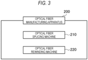
- an optical fiber manufacturing apparatus 200 used in the optical fiber manufacturing method according to the second embodiment will be described with reference to FIGS. 3 and 4 .
- FIG. 3 is a schematic diagram of an optical fiber manufacturing apparatus according to the second embodiment of the present disclosure
- FIG. 4 is a schematic view of an optical fiber rewinding machine according to the second embodiment of the present disclosure.
- the optical fiber manufacturing apparatus 200 is an apparatus configured to manufacture one optical fiber from two optical fibers. As illustrated in FIG. 3 , the optical fiber manufacturing apparatus 200 includes an optical fiber splicing machine 210 configured to splice the two optical fibers, and an optical fiber rewinding machine 220 configured to wind the one optical fiber produced by the optical fiber splicing machine 210 around a prescribed bobbin.
- the optical fiber splicing machine 210 is the same as the optical fiber splicing machine 110 according to the first embodiment. Accordingly, detailed description thereof will be omitted and only reference numerals in a 200 range having the same last two digits will be assigned.
- the optical fiber rewinding machine 220 includes a first bobbin mounting shaft 221 to which the first bobbin B1 in a state where the first optical fiber F1 and the second optical fiber F2 are spliced to form the third optical fiber F3 is configured to be mounted, and a second bobbin mounting shaft 222 to which the second bobbin B2 in a state where the first optical fiber F1 and the second optical fiber F2 are spliced to form the third optical fiber F3 is configured to be mounted.
- a path line PL which is a traveling path of the third optical fiber F3, is formed between the first bobbin mounting shaft 221 and the second bobbin mounting shaft 222.
- two capstans 223 configured to apply a prescribed tension to the third optical fiber F3, a screening roller 224 provided between the two capstans 223, dancer rollers 225 configured to absorb fluctuations in speed and tension of the third optical fiber F3, a plurality of guide rollers 226 configured to change a traveling direction of the optical fiber, and an unevenness detection unit 227 configured to detect an uneven shape on a surface of the third optical fiber F3.
- the dancer roller 225 is configured to swing about a swing shaft 225A.
- One dancer roller 225 is provided upstream of an upstream capstan (first capstan) 223a and one dancer roller 225 is provided downstream of a downstream capstan (second capstan) 223b.
- the respective dancer rollers 225 are provided upstream and downstream of the screening roller 224.
- the plurality of guide rollers 226 are provided in a vicinity of the first bobbin B1 mounted on the first bobbin mounting shaft 221 and the second bobbin B2 mounted on the second bobbin mounting shaft 222.
- an upstream dancer roller 225a is provided between the upstream capstan 223a and an upstream guide roller 226a
- a downstream dancer roller 225b is provided between the downstream capstan 223b and a downstream guide roller 226b.
- the unevenness detection unit 227 is provided between the downstream guide rollers 226b.
- the optical fiber rewinding machine 220 further includes a plurality of temporary hooks 228 for temporarily suspending the third optical fiber F3.
- three temporary hooks 228 are provided in a horizontal row.
- the temporary hook 228 has a smooth surface so as not to damage the third optical fiber F3.
- the third optical fiber F3 having both sides wound around the first bobbin B1 and the second bobbin B2 can be easily wound around the rewinding machine 220.
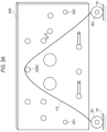
- FIGS. 5A to 5F illustrate procedures of suspending an optical fiber in the optical fiber rewinding machine in FIG. 4
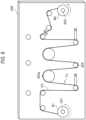
- FIG. 6 illustrates a fiber reverse running step.
- the first bobbin B1 around which the screened first optical fiber F1 is wound and the second bobbin B2 around which the screened second optical fiber F2 is wound are prepared in advance, which is similar to that in the first embodiment.
- Screening of the first optical fiber F1 and the second optical fiber F2 may be to apply tension at an elongation of 1.5% or more and 2.0% or less to the first optical fiber F1 and the second optical fiber F2, which is similar to that in the first embodiment.
- the first bobbin B1 is mounted on the first bobbin mounting shaft 211 of the optical fiber splicing machine 210
- the second bobbin B2 is mounted on the second bobbin mounting shaft 212 of the optical fiber splicing machine 210.
- the first optical fiber F1 and the second optical fiber F2 are fed and inserted into a fiber splicing unit 213 of the optical fiber splicing machine 210.
- the fiber splicing unit 213 joins an upper port of the first optical fiber F1 and an upper port of the second optical fiber F2 to produce the third optical fiber F3.
- the first bobbin B1 and the second bobbin B2 are removed from the optical fiber splicing machine 210 and mounted on the optical fiber rewinding machine 220.
- the third optical fiber F3 is suspended on a central temporary hook 228C in a state where the first bobbin B1 and the second bobbin B2 are placed on a temporary face TF.
- the first bobbin B1 is mounted on the first bobbin mounting shaft 221 of the optical fiber rewinding machine 220
- the second bobbin B2 is mounted on the second bobbin mounting shaft 222 of the optical fiber rewinding machine 220.
- the third optical fiber F3 is suspended on a left temporary hook 228L and a right temporary hook 228R.
- the third optical fiber F3 is removed from the left temporary hook 228L, and suspended on the upstream guide roller 226a, the upstream dancer roller 225a, and the upstream capstan 223a in this order.
- the third optical fiber F3 is removed from the central temporary hook 228C, and suspended on the screening roller 224, the downstream capstan 223b, and the downstream dancer roller 225b in this order.
- the third optical fiber F3 is removed from the right temporary hook 228R, and is suspended on the downstream guide roller 226b while passing through the unevenness detection unit 227.
- a splicing portion Fc of the first optical fiber F1 and the second optical fiber F2 may be located downstream of a section between the upstream capstan 223a and the downstream capstan 223b, which is a section in which screening is executed.
- the splicing portion Fc of the first optical fiber F1 and the second optical fiber F2 is a part that is most likely to induce a quality defect as an optical fiber, and it is desired to always inspect the splicing portion Fc of the first optical fiber F1 and the second optical fiber F2.
- the first bobbin mounting shaft 221 is reversely rotated (that is, rotated in a direction in which the splicing portion Fc approaches the first bobbin B1) to reversely convey the third optical fiber F3, and a part of the third optical fiber F3 is wound around the first bobbin B1.
- a part of the third optical fiber F3 is wound around the first bobbin B1 until the splicing portion Fc of the first optical fiber F1 and the second optical fiber F2 is located upstream of the upstream capstan 223a.
- the following screening step is performed.
- the third optical fiber F3 is fed from the first bobbin B1 to the second bobbin B2, screened by being applied with a prescribed tension between the upstream capstan 223a and the downstream capstan 223b, checked by the unevenness detection unit 227 for unevenness on a surface of the third optical fiber F3, and wound around the second bobbin B2.
- Screening of the third optical fiber F3 may be to apply tension at an elongation of 0.3% or more and 2.0% or less to the third optical fiber F3.
- the screening of the third optical fiber F3 may be to apply, to the third optical fiber F3, tension at an elongation equal to or smaller than that when screening the first optical fiber F1 and screening the second optical fiber F2.
- the unevenness detection unit 227 may determine that the surface of the third optical fiber F3 is defective when the amount of unevenness on the surface of the third optical fiber F3 exceeds a prescribed range.
- the "prescribed range” may be a range in which the amount of decrease in an outer diameter of the third optical fiber F3 is 30 ⁇ m or less and the amount of increase in the outer diameter of the third optical fiber F3 is 50 ⁇ m or less.
- a winding speed around the second bobbin B2 by the optical fiber rewinding machine 220 may be 300 m/min or more and 2000 m/min or less.
- the optical fiber splicing method executed in this manner includes the fiber splicing step of splicing the first optical fiber F1 and the second optical fiber F2 to produce the third optical fiber F3, and the screening step of feeding the third optical fiber F3 from the first bobbin B1, screening the third optical fiber F3, and winding the third optical fiber F3 around the second bobbin B2, and thereby the third optical fiber F3 obtained by splicing the first optical fiber F1 and the second optical fiber F2 is screened. Accordingly, it is possible to efficiently detect a defect of the third optical fiber F3 obtained by splicing the first optical fiber F1 and the second optical fiber F2.
- the optical fiber splicing method further includes the fiber reverse running step of winding the third optical fiber F3 around the first bobbin B1 after the fiber splicing step and before the screening step. Accordingly, a screening range for the third optical fiber F3 is widened, and thus a defect of the third optical fiber F3 can be more easily detected.
- the third optical fiber F3 is wound around the first bobbin B1 until the splicing portion Fc of the first optical fiber F1 and the second optical fiber F2 is located upstream of the section in which the screening is executed. Accordingly, the splicing portion Fc of the first optical fiber F1 and the second optical fiber F2 that is most likely to be a defective portion is always screened, and thus a defect of the third optical fiber F3 can be reliably detected.
- the optical fiber rewinding machine includes the upstream capstan 223a, which is the first capstan provided on the path line PL of the third optical fiber F3 formed between the first bobbin mounting shaft 221 and the second bobbin mounting shaft 222, and the downstream capstan 223b, which is the second capstan provided downstream of the upstream capstan 223a on the path line PL. Accordingly, the third optical fiber F3 obtained by splicing the first optical fiber F1 and the second optical fiber F2 is screened by being applied with the prescribed tension between the first capstan and the second capstan, and thus the defect of the third optical fiber F3 obtained by splicing the first optical fiber F1 and the second optical fiber F2 can be detected.
- the temporary hook may have an L shape in a side view to prevent the optical fiber from falling off.
Landscapes
- Physics & Mathematics (AREA)
- General Physics & Mathematics (AREA)
- Engineering & Computer Science (AREA)
- Manufacturing & Machinery (AREA)
- Optics & Photonics (AREA)
- Chemical & Material Sciences (AREA)
- Analytical Chemistry (AREA)
- Filamentary Materials, Packages, And Safety Devices Therefor (AREA)
- Testing Of Optical Devices Or Fibers (AREA)
Abstract
Description
- The present disclosure relates to an optical fiber manufacturing method and an optical fiber rewinding machine.
- The present application claims priority based on
Japanese Patent Application No. 2022-123778 filed on August 3, 2022 - As an optical fiber manufacturing method of one optical fiber by splicing two optical fibers in the related art, there is known an optical fiber splicing method in which coating layers are partially removed to expose optical fibers, the exposed two optical fibers are subject to fusion splicing to form an optical fiber splicing portion of the coating layers, the optical fiber splicing portion is disposed in a prescribed mold, and a resin is dropped on one of the coating layers (for example, see Patent Literature 1).
- Patent Literature 1:
JP2017-49400A - According to the present disclosure, an optical fiber manufacturing method includes a fiber splicing step of splicing a first optical fiber wound around a first bobbin and a second optical fiber wound around a second bobbin to produce a third optical fiber; a fiber winding step of winding the third optical fiber around the second bobbin, in an optical fiber rewinding machine; and a screening step of feeding the third optical fiber from the second bobbin by the optical fiber rewinding machine, screening the third optical fiber, and winding the third optical fiber around a third bobbin, in an optical fiber rewinding machine.
- According to the present disclosure, another optical fiber manufacturing method includes a fiber splicing step of splicing a first optical fiber wound around a first bobbin and a second optical fiber wound around a second bobbin to produce a third optical fiber; and a screening step of feeding the third optical fiber from the first bobbin, screening the third optical fiber, and winding the third optical fiber around the second bobbin.
- According to the present disclosure, an optical fiber rewinding machine for winding, around a second bobbin, a third optical fiber obtained by splicing a screened first optical fiber wound around a first bobbin and a screened second optical fiber wound around the second bobbin, the optical fiber rewinding machine includes a first bobbin mounting shaft to which the first bobbin is configured to be mounted; a second bobbin mounting shaft to which the second bobbin is configured to be mounted; a first capstan provided on a path line of the third optical fiber, the path line being formed between the first bobbin mounting shaft and the second bobbin mounting shaft; and a second capstan provided on the path line and downstream of the first capstan.
- "Screening" used here refers to a "proof test (screening test) in which a prescribed tension is applied to a portion of a path line to break and remove a weak part in order to ensure a lifespan of an optical fiber before breakage".
-
- [
FIG. 1] FIG. 1 is a schematic diagram of an optical fiber manufacturing apparatus according to a first embodiment of the present disclosure. - [
FIG. 2A] FIG. 2A illustrates an optical fiber splicing machine inFIG. 1 and a fiber splicing step by the optical fiber splicing machine. - [
FIG. 2B] FIG. 2B illustrates an optical fiber rewinding machine inFIG. 1 and an optical fiber screening step by the optical fiber rewinding machine. - [
FIG. 3] FIG. 3 is a schematic diagram of an optical fiber manufacturing apparatus according to a second embodiment of the present disclosure. - [
FIG. 4] FIG. 4 is a schematic view of an optical fiber rewinding machine according to the second embodiment of the present disclosure. - [
FIG. 5A] FIG. 5A illustrates a procedure of suspending an optical fiber on the optical fiber rewinding machine inFIG. 4 . - [
FIG. 5B] FIG. 5B illustrates a procedure of suspending the optical fiber on the optical fiber rewinding machine inFIG. 4 . - [
FIG. 5C] FIG. 5C illustrates a procedure of suspending the optical fiber on the optical fiber rewinding machine inFIG. 4 . - [
FIG. 5D] FIG. 5D illustrates a procedure of suspending the optical fiber on the optical fiber rewinding machine inFIG. 4 . - [
FIG. 5E] FIG. 5E illustrates a procedure of suspending the optical fiber on the optical fiber rewinding machine inFIG. 4 . - [
FIG. 5F] FIG. 5F illustrates a procedure of suspending the optical fiber on the optical fiber rewinding machine inFIG. 4 . - [
FIG. 6] FIG. 6 illustrates a fiber reverse running step. - One optical fiber obtained by splicing two optical fibers in this way may be rewound around a bobbin, and the two optical fibers may not be sufficiently spliced or a defect may occur in the optical fiber when being rewound around the bobbin.
- For this reason, it is necessary to screen the spliced optical fiber over an entire length thereof with another facility after the rewinding, which is troublesome.
- Therefore, the present disclosure is to solve the problem in the related art as described above, that is, an object of the present disclosure is to provide an optical fiber manufacturing method and an optical fiber rewinding machine that efficiently detect a defect of a third optical fiber obtained by splicing a first optical fiber and a second optical fiber.
- According to the above, it is possible to efficiently detect a defect of a third optical fiber obtained by splicing a first optical fiber and a second optical fiber.
- First, contents of aspects of the present disclosure will be listed and described.
- According to the present disclosure, (1) an optical fiber manufacturing method includes a fiber splicing step of splicing a first optical fiber wound around a first bobbin and a second optical fiber wound around a second bobbin to produce a third optical fiber; a fiber winding step of winding the third optical fiber around the second bobbin by an optical fiber rewinding machine; and a screening step of feeding the third optical fiber from the second bobbin, in the optical fiber rewinding machine, screening the third optical fiber, and winding the third optical fiber around a third bobbin, in the optical fiber rewinding machine.
- In this manner, the third optical fiber obtained by splicing the first optical fiber and the second optical fiber is screened by the fiber splicing step of splicing the first optical fiber wound around the first bobbin and the second optical fiber wound around the second bobbin to produce the third optical fiber, the fiber winding step of winding the third optical fiber around the second bobbin by the optical fiber rewinding machine, and the screening step of feeding the third optical fiber from the second bobbin by the optical fiber rewinding machine, screening the third optical fiber, and winding the third optical fiber around the third bobbin, and thereby. Accordingly, it is possible to efficiently detect a defect of the third optical fiber obtained by splicing the first optical fiber and the second optical fiber.
- According to the present disclosure, (2) another optical fiber manufacturing method of manufacturing a third optical fiber from a screened first optical fiber wound around a first bobbin and a screened second optical fiber wound around a second bobbin includes: a fiber splicing step of splicing the first optical fiber wound around the first bobbin and the second optical fiber wound around the second bobbin to produce the third optical fiber; and a screening step of feeding the third optical fiber from the first bobbin, screening the third optical fiber, and winding the third optical fiber around the second bobbin.
- In this manner, the third optical fiber obtained by splicing the first optical fiber and the second optical fiber is screened by the fiber splicing step of splicing the first optical fiber wound around the first bobbin and the second optical fiber wound around the second bobbin to produce the third optical fiber, and the screening step of feeding the third optical fiber from the first bobbin, screening the third optical fiber, and winding the third optical fiber around the second bobbin. Accordingly, it is possible to efficiently detect a defect of the third optical fiber obtained by splicing the first optical fiber and the second optical fiber.
- (3) The above optical fiber manufacturing method further includes a fiber reverse running step of winding the third optical fiber around the first bobbin after the fiber splicing step and before the screening step.
- Accordingly, a screening range for the third optical fiber is widened, and thus a defect of the third optical fiber can be more easily detected.
- (4) In the fiber reverse running step in the above optical fiber manufacturing method, the third optical fiber is wound around the first bobbin until a splicing portion of the first optical fiber and the second optical fiber is located closer to the first bobbin than to a section in which screening is executed.
- Accordingly, the splicing portion of the first optical fiber and the second optical fiber, which is most likely to be a defective portion, is always screened, and thus a defect of the third optical fiber can be reliably detected.
- According to the present disclosure, (5) an optical fiber rewinding machine for winding, around a second bobbin, a third optical fiber obtained by splicing a screened first optical fiber wound around a first bobbin and a screened second optical fiber wound around the second bobbin, the optical fiber rewinding machine includes a first bobbin mounting shaft to which the first bobbin is configured to be mounted; a second bobbin mounting shaft to which the second bobbin is configured to be mounted; a first capstan provided on a path line of the third optical fiber, the path line being formed between the first bobbin mounting shaft and the second bobbin mounting shaft; and a second capstan provided on the path line and downstream of the first capstan.
- In this manner, by providing the first capstan provided on the path line of the third optical fiber formed between the first bobbin mounting shaft and the second bobbin mounting shaft, and the second capstan provided downstream of the first capstan on the path line, the third optical fiber obtained by splicing the first optical fiber and the second optical fiber is screened by being applied with the prescribed tension between the first capstan and the second capstan, and thus the defect of the third optical fiber obtained by splicing the first optical fiber and the second optical fiber can be detected.
- Further, a screening roller that changes a traveling direction of the third optical fiber may be provided between the first capstan and the second capstan on the path line.
- (6) The above optical fiber rewinding machine further includes an unevenness detection unit provided downstream of the second capstan and configured to detect an uneven shape on a surface of the third optical fiber.
- Accordingly, when a coating of the optical fiber is deformed on the first capstan or the second capstan, a defective portion due to the deformation can be reliably detected.
- (7) The optical fiber rewinding machine further includes a temporary hook configured to temporarily suspend the third optical fiber.
- Accordingly, the third optical fiber having both sides wound around the first bobbin and the second bobbin can be easily wound around the optical fiber rewinding machine.
- Details of Embodiments of Present Disclosure
- Hereinafter, specific examples of an optical fiber manufacturing method and an optical fiber rewinding machine according to the present disclosure will be described.
- First, an optical fiber manufacturing method according to a first embodiment will be described with reference to
FIGS. 1 to 2B . -
FIG. 1 is a schematic diagram of an optical fiber manufacturing apparatus according to the first embodiment of the present disclosure,FIG. 2A illustrates an optical fiber splicing machine inFIG. 1 and a fiber splicing step by the optical fiber splicing machine, andFIG. 2B illustrates an optical fiber rewinding machine inFIG. 1 and an optical fiber screening step by the optical fiber rewinding machine. - An optical
fiber manufacturing apparatus 100 is an apparatus configured to manufacture one optical fiber from two optical fibers. As illustrated inFIG. 1 , the opticalfiber manufacturing apparatus 100 includes an opticalfiber splicing machine 110 configured to splice the two optical fibers, and an opticalfiber rewinding machine 120 configured to wind the one optical fiber produced by the opticalfiber splicing machine 110 around a prescribed bobbin and inspect the optical fiber. - As illustrated in
FIG. 2A , the opticalfiber splicing machine 110 includes a firstbobbin mounting shaft 111 to which a first bobbin B1 around which a screened first optical fiber F1 is wound is configured to be mounted, a secondbobbin mounting shaft 112 to which a second bobbin B2 around which a screened second optical fiber F2 is wound is configured to be mounted, and afiber splicing unit 113 configured to splice the first optical fiber F1 and the second optical fiber F2. - Screening of the first optical fiber F1 may be to apply tension at an elongation of 1.5% or more and 2.0% or less to the first optical fiber F1. The same applies to screening of the second optical fiber F2.
- As illustrated in
FIG. 2B , the opticalfiber rewinding machine 120 includes a secondbobbin mounting shaft 122 to which the first bobbin B1 in a state where the first optical fiber F1 and the second optical fiber F2 are spliced to form a third optical fiber F3 or a third bobbin B3 on which the third optical fiber F3 is wound is configured to be mounted, a firstbobbin mounting shaft 121 to which the second bobbin B2 in a state where the first optical fiber F1 and the second optical fiber F2 are spliced to form the third optical fiber F3 is configured to be mounted, and afiber inspection mechanism 123 that is provided between the firstbobbin mounting shaft 121 and the secondbobbin mounting shaft 122 and configured to guide the third optical fiber F3 on a path line. - The
fiber inspection mechanism 123 includes ascreening unit 123a configured to screen the third optical fiber F3, and anunevenness detection unit 123b that is provided downstream of thescreening unit 123a and configured to detect an uneven shape on a surface of the third optical fiber F3. - Next, an optical fiber manufacturing method using the optical
fiber manufacturing apparatus 100 described above will be described with reference toFIGS. 2A and 2B . - The first bobbin B1 around which the screened first optical fiber F1 is wound and the second bobbin B2 around which the screened second optical fiber F2 is wound are prepared in advance.
- Next, the first bobbin B1 is mounted on the first
bobbin mounting shaft 111 of the opticalfiber splicing machine 110, and the second bobbin B2 is mounted on the secondbobbin mounting shaft 112 of the opticalfiber splicing machine 110. - In this state, as illustrated in
FIG. 2A , the first optical fiber F1 and the second optical fiber F2 are fed from the first bobbin B1 and the second bobbin B2, respectively, and inserted into thefiber splicing unit 113 of the opticalfiber splicing machine 110. - Then, the
fiber splicing unit 113 joins an upper port (a tip of the optical fiber on an outer circumferential side of the bobbin) of the first optical fiber F1 and an upper port of the second optical fiber F2 to produce the third optical fiber F3. - Next, in a state where the third optical fiber F3 is produced, the first bobbin B1 and the second bobbin B2 are removed from the optical
fiber splicing machine 110 and mounted on the opticalfiber rewinding machine 120. - Specifically, the first bobbin B1 is mounted on the second
bobbin mounting shaft 122 of the opticalfiber rewinding machine 120, and the second bobbin B2 is mounted on the firstbobbin mounting shaft 121 of the opticalfiber rewinding machine 120. - In this state, the first
bobbin mounting shaft 121 rotates until the entire third optical fiber F3 is wound around the second bobbin B2. - Next, the first bobbin B1 is removed from the optical
fiber rewinding machine 120, and the empty third bobbin B3 is mounted on the opticalfiber rewinding machine 120. - In this state, as illustrated in
FIG. 2B , the third optical fiber F3 is fed from the second bobbin B2 to the third bobbin B3, screened by thescreening unit 123a of the opticalfiber rewinding machine 120, checked by theunevenness detection unit 123b for unevenness on a surface thereof, and wound around the third bobbin B3. - Screening of the third optical fiber F3 may be to apply tension at an elongation of 0.3% or more and 2.0% or less to the third optical fiber F3.
- That is, the screening of the third optical fiber F3 may be to apply, to the third optical fiber F3, tension at an elongation equal to or smaller than that when screening the first optical fiber F1 and screening the second optical fiber F2.
- The
unevenness detection unit 123b may be configured to determine that the surface of the third optical fiber F3 is defective when the amount of unevenness on the surface of the third optical fiber F3 exceeds a prescribed range. - Here, the "prescribed range" may be a range in which the amount of decrease in an outer diameter of the third optical fiber F3 is 30 µm or less and the amount of increase in the outer diameter of the third optical fiber F3 is 50 µm or less.
- Further, a winding speed around the third bobbin B3 by the optical
fiber rewinding machine 120 may be 300 m/min or more and 2000 m/min or less. - When the winding speed at which the optical fiber is wound around the third bobbin B3 by the optical
fiber rewinding machine 120 is lower than 300 m/min, a coating of a splicing portion of the first optical fiber F1 and the second optical fiber F2 is likely to be deformed. - When the winding speed at which the optical fiber is wound around the third bobbin B3 by the optical
fiber rewinding machine 120 is faster than 2000 m/min, rewinding time of the third optical fiber F3 for inspecting a defective portion when theunevenness detection unit 123b determines the defective portion becomes long. - The optical fiber splicing method executed in this manner includes the fiber splicing step of splicing the first optical fiber F1 and the second optical fiber F2 to produce the third optical fiber F3, the fiber winding step of winding the third optical fiber F3 around the second bobbin B2 by the optical
fiber rewinding machine 120, and the screening step of feeding the third optical fiber F3 from the second bobbin B2 by the opticalfiber rewinding machine 120, screening the third optical fiber F3, and winding the third optical fiber F3 around the third bobbin B3, and thereby the third optical fiber F3 obtained by splicing the first optical fiber F1 and the second optical fiber F2 is screened. Accordingly, it is possible to efficiently detect a defect of the third optical fiber F3 obtained by splicing the first optical fiber F1 and the second optical fiber F2. - Next, an optical fiber manufacturing method according to a second embodiment will be described with reference to
FIGS. 3 to 6 . - First, an optical
fiber manufacturing apparatus 200 used in the optical fiber manufacturing method according to the second embodiment will be described with reference toFIGS. 3 and4 . -
FIG. 3 is a schematic diagram of an optical fiber manufacturing apparatus according to the second embodiment of the present disclosure, andFIG. 4 is a schematic view of an optical fiber rewinding machine according to the second embodiment of the present disclosure. - The optical
fiber manufacturing apparatus 200 is an apparatus configured to manufacture one optical fiber from two optical fibers. As illustrated inFIG. 3 , the opticalfiber manufacturing apparatus 200 includes an opticalfiber splicing machine 210 configured to splice the two optical fibers, and an opticalfiber rewinding machine 220 configured to wind the one optical fiber produced by the opticalfiber splicing machine 210 around a prescribed bobbin. - The optical
fiber splicing machine 210 is the same as the opticalfiber splicing machine 110 according to the first embodiment. Accordingly, detailed description thereof will be omitted and only reference numerals in a 200 range having the same last two digits will be assigned. - As illustrated in
FIG. 4 , the opticalfiber rewinding machine 220 includes a firstbobbin mounting shaft 221 to which the first bobbin B1 in a state where the first optical fiber F1 and the second optical fiber F2 are spliced to form the third optical fiber F3 is configured to be mounted, and a secondbobbin mounting shaft 222 to which the second bobbin B2 in a state where the first optical fiber F1 and the second optical fiber F2 are spliced to form the third optical fiber F3 is configured to be mounted. - When the first bobbin B1 is mounted on the first
bobbin mounting shaft 221 and the second bobbin B2 is mounted on the secondbobbin mounting shaft 222, respectively, a path line PL, which is a traveling path of the third optical fiber F3, is formed between the firstbobbin mounting shaft 221 and the secondbobbin mounting shaft 222. - Provided on the path line PL, as illustrated in
FIG. 4 , are twocapstans 223 configured to apply a prescribed tension to the third optical fiber F3, ascreening roller 224 provided between the twocapstans 223,dancer rollers 225 configured to absorb fluctuations in speed and tension of the third optical fiber F3, a plurality ofguide rollers 226 configured to change a traveling direction of the optical fiber, and anunevenness detection unit 227 configured to detect an uneven shape on a surface of the third optical fiber F3. - As illustrated in
FIG. 4 , thedancer roller 225 is configured to swing about aswing shaft 225A. Onedancer roller 225 is provided upstream of an upstream capstan (first capstan) 223a and onedancer roller 225 is provided downstream of a downstream capstan (second capstan) 223b. - Therefore, the
respective dancer rollers 225 are provided upstream and downstream of thescreening roller 224. - This makes it possible to stably apply tension to the third optical fiber F3 between the two
capstans 223. - As illustrated in
FIG. 4 , the plurality ofguide rollers 226 are provided in a vicinity of the first bobbin B1 mounted on the firstbobbin mounting shaft 221 and the second bobbin B2 mounted on the secondbobbin mounting shaft 222. - Therefore, as illustrated in
FIG. 4 , anupstream dancer roller 225a is provided between theupstream capstan 223a and anupstream guide roller 226a, and adownstream dancer roller 225b is provided between thedownstream capstan 223b and adownstream guide roller 226b. - As illustrated in
FIG. 4 , theunevenness detection unit 227 is provided between thedownstream guide rollers 226b. - As illustrated in
FIG. 4 , the opticalfiber rewinding machine 220 further includes a plurality oftemporary hooks 228 for temporarily suspending the third optical fiber F3. - For example, as illustrated in
FIG. 4 , threetemporary hooks 228 are provided in a horizontal row. - The
temporary hook 228 has a smooth surface so as not to damage the third optical fiber F3. - In the optical
fiber rewinding machine 220 described above, no roller winds an optical fiber on an entire circumference thereof on the path line PL. - This makes it less likely for the optical fiber to be twisted when the optical fiber is wound around rollers.
- In addition, the third optical fiber F3 having both sides wound around the first bobbin B1 and the second bobbin B2 can be easily wound around the rewinding
machine 220. - Next, the optical fiber manufacturing method using the optical
fiber manufacturing apparatus 200 described above will be described with reference toFIGS. 5A to 6 . -
FIGS. 5A to 5F illustrate procedures of suspending an optical fiber in the optical fiber rewinding machine inFIG. 4 , andFIG. 6 illustrates a fiber reverse running step. - Also in the second embodiment, the first bobbin B1 around which the screened first optical fiber F1 is wound and the second bobbin B2 around which the screened second optical fiber F2 is wound are prepared in advance, which is similar to that in the first embodiment.
- Screening of the first optical fiber F1 and the second optical fiber F2 may be to apply tension at an elongation of 1.5% or more and 2.0% or less to the first optical fiber F1 and the second optical fiber F2, which is similar to that in the first embodiment.
- Next, the first bobbin B1 is mounted on the first bobbin mounting shaft 211 of the optical
fiber splicing machine 210, and the second bobbin B2 is mounted on the second bobbin mounting shaft 212 of the opticalfiber splicing machine 210. - In this state, the first optical fiber F1 and the second optical fiber F2 are fed and inserted into a fiber splicing unit 213 of the optical
fiber splicing machine 210. - Then, the fiber splicing unit 213 joins an upper port of the first optical fiber F1 and an upper port of the second optical fiber F2 to produce the third optical fiber F3.
- Next, in a state where the third optical fiber F3 is produced, the first bobbin B1 and the second bobbin B2 are removed from the optical
fiber splicing machine 210 and mounted on the opticalfiber rewinding machine 220. - Hereinafter, an example of a bobbin mounting step to the optical
fiber rewinding machine 220 will be described. - In the bobbin mounting step, as illustrated in
FIG. 5A , first, the third optical fiber F3 is suspended on a centraltemporary hook 228C in a state where the first bobbin B1 and the second bobbin B2 are placed on a temporary face TF. - In this state, as illustrated in
FIG. 5B , the first bobbin B1 is mounted on the firstbobbin mounting shaft 221 of the opticalfiber rewinding machine 220, and the second bobbin B2 is mounted on the secondbobbin mounting shaft 222 of the opticalfiber rewinding machine 220. - Subsequently, as illustrated in
FIG. 5C , the third optical fiber F3 is suspended on a lefttemporary hook 228L and a righttemporary hook 228R. - Then, as illustrated in
FIG. 5D , the third optical fiber F3 is removed from the lefttemporary hook 228L, and suspended on theupstream guide roller 226a, theupstream dancer roller 225a, and theupstream capstan 223a in this order. - Then, as illustrated in
FIG. 5E , the third optical fiber F3 is removed from the centraltemporary hook 228C, and suspended on thescreening roller 224, thedownstream capstan 223b, and thedownstream dancer roller 225b in this order. - Subsequently, as illustrated in
FIG. 5F , the third optical fiber F3 is removed from the righttemporary hook 228R, and is suspended on thedownstream guide roller 226b while passing through theunevenness detection unit 227. - When the third optical fiber F3 is suspended on the optical
fiber rewinding machine 220 in this manner, as illustrated inFIG. 5F , a splicing portion Fc of the first optical fiber F1 and the second optical fiber F2 may be located downstream of a section between theupstream capstan 223a and thedownstream capstan 223b, which is a section in which screening is executed. - The splicing portion Fc of the first optical fiber F1 and the second optical fiber F2 is a part that is most likely to induce a quality defect as an optical fiber, and it is desired to always inspect the splicing portion Fc of the first optical fiber F1 and the second optical fiber F2.
- Therefore, the following fiber reverse running step is performed before the screening step to be described later.
- In the fiber reverse running step, as illustrated in
FIG. 6 , the firstbobbin mounting shaft 221 is reversely rotated (that is, rotated in a direction in which the splicing portion Fc approaches the first bobbin B1) to reversely convey the third optical fiber F3, and a part of the third optical fiber F3 is wound around the first bobbin B1. - More specifically, a part of the third optical fiber F3 is wound around the first bobbin B1 until the splicing portion Fc of the first optical fiber F1 and the second optical fiber F2 is located upstream of the
upstream capstan 223a. - After the splicing portion Fc of the first optical fiber F1 and the second optical fiber F2 is returned upstream of the section in which the screening is executed as illustrated in
FIG. 6 by the fiber reverse running step, the following screening step is performed. - In the screening step, the third optical fiber F3 is fed from the first bobbin B1 to the second bobbin B2, screened by being applied with a prescribed tension between the
upstream capstan 223a and thedownstream capstan 223b, checked by theunevenness detection unit 227 for unevenness on a surface of the third optical fiber F3, and wound around the second bobbin B2. - In the screening step, a torque difference is generated between the
upstream capstan 223a and thedownstream capstan 223b since the tension is applied to the third optical fiber F3. - Screening of the third optical fiber F3 may be to apply tension at an elongation of 0.3% or more and 2.0% or less to the third optical fiber F3.
- That is, the screening of the third optical fiber F3 may be to apply, to the third optical fiber F3, tension at an elongation equal to or smaller than that when screening the first optical fiber F1 and screening the second optical fiber F2.
- The
unevenness detection unit 227 may determine that the surface of the third optical fiber F3 is defective when the amount of unevenness on the surface of the third optical fiber F3 exceeds a prescribed range. - Here, the "prescribed range" may be a range in which the amount of decrease in an outer diameter of the third optical fiber F3 is 30 µm or less and the amount of increase in the outer diameter of the third optical fiber F3 is 50 µm or less.
- Further, a winding speed around the second bobbin B2 by the optical
fiber rewinding machine 220 may be 300 m/min or more and 2000 m/min or less. - When the winding speed at which the optical fiber is wound around the third bobbin B3 by the optical
fiber rewinding machine 220 is lower than 300 m/min, a coating of a splicing portion of the first optical fiber F1 and the second optical fiber F2 is likely to be deformed. - When the winding speed at which the optical fiber is wound around the third bobbin B3 by the optical
fiber rewinding machine 220 is higher than 2000 m/min, rewinding time of the third optical fiber F3 for inspecting a defective portion when theunevenness detection unit 227 determines the defective portion becomes long. - The optical fiber splicing method executed in this manner includes the fiber splicing step of splicing the first optical fiber F1 and the second optical fiber F2 to produce the third optical fiber F3, and the screening step of feeding the third optical fiber F3 from the first bobbin B1, screening the third optical fiber F3, and winding the third optical fiber F3 around the second bobbin B2, and thereby the third optical fiber F3 obtained by splicing the first optical fiber F1 and the second optical fiber F2 is screened. Accordingly, it is possible to efficiently detect a defect of the third optical fiber F3 obtained by splicing the first optical fiber F1 and the second optical fiber F2.
- The optical fiber splicing method further includes the fiber reverse running step of winding the third optical fiber F3 around the first bobbin B1 after the fiber splicing step and before the screening step. Accordingly, a screening range for the third optical fiber F3 is widened, and thus a defect of the third optical fiber F3 can be more easily detected.
- Further, in the fiber reverse running step, the third optical fiber F3 is wound around the first bobbin B1 until the splicing portion Fc of the first optical fiber F1 and the second optical fiber F2 is located upstream of the section in which the screening is executed. Accordingly, the splicing portion Fc of the first optical fiber F1 and the second optical fiber F2 that is most likely to be a defective portion is always screened, and thus a defect of the third optical fiber F3 can be reliably detected.
- Further, the optical fiber rewinding machine according to the present embodiment includes the
upstream capstan 223a, which is the first capstan provided on the path line PL of the third optical fiber F3 formed between the firstbobbin mounting shaft 221 and the secondbobbin mounting shaft 222, and thedownstream capstan 223b, which is the second capstan provided downstream of theupstream capstan 223a on the path line PL. Accordingly, the third optical fiber F3 obtained by splicing the first optical fiber F1 and the second optical fiber F2 is screened by being applied with the prescribed tension between the first capstan and the second capstan, and thus the defect of the third optical fiber F3 obtained by splicing the first optical fiber F1 and the second optical fiber F2 can be detected. - Although embodiments of the present disclosure are described above, the present disclosure is not limited thereto.
- Elements provided in the embodiments described above can be combined as long as it is technically possible, and a combination thereof is also included in the scope of the present disclosure as long as the features of the present disclosure are included.
- For example, three temporary hooks are provided in the second embodiment described above, but the number of temporary hooks to be provided is not limited to three.
- The temporary hook may have an L shape in a side view to prevent the optical fiber from falling off.
-
- 100 optical fiber manufacturing apparatus
- 110 optical fiber splicing machine
- 111 first bobbin mounting shaft
- 112 second bobbin mounting shaft
- 113 fiber splicing unit
- 120 optical fiber rewinding machine
- 121 first bobbin mounting shaft
- 122 second bobbin mounting shaft
- 123 fiber inspection mechanism
- 123a screening unit
- 123b unevenness detection unit
- 200 optical fiber manufacturing apparatus
- 210 optical fiber splicing machine
- 211 first bobbin mounting shaft
- 212 second bobbin mounting shaft
- 220 optical fiber rewinding machine
- 221 first bobbin mounting shaft
- 222 second bobbin mounting shaft
- 223 capstan
- 223a upstream capstan (first capstan)
- 223b downstream capstan (second capstan)
- 224 screening roller
- 225 dancer roller
- 225A swing shaft
- 225a upstream dancer roller
- 225b downstream dancer roller
- 226 guide roller
- 226a upstream guide roller
- 226b downstream guide roller
- 227 unevenness detection unit
- 228 temporary hook
- 228L left temporary hook
- 228C central temporary hook
- 228R right temporary hook
- B1 first bobbin
- B2 second bobbin
- B3 third bobbin
- F1 first optical fiber
- F2 second optical fiber
- F3 third optical fiber
- Fc splicing portion
- PL path line
- TF temporary face
Claims (7)
- An optical fiber manufacturing method comprising:a fiber splicing step of splicing a first optical fiber wound around a first bobbin and a second optical fiber wound around a second bobbin to produce a third optical fiber;a fiber winding step of winding the third optical fiber around the second bobbin, in an optical fiber rewinding machine; anda screening step of feeding the third optical fiber from the second bobbin, screening the third optical fiber, and winding the third optical fiber around a third bobbin, in the optical fiber rewinding machine.
- An optical fiber manufacturing method comprising:a fiber splicing step of splicing a first optical fiber wound around a first bobbin and a second optical fiber wound around a second bobbin to produce a third optical fiber; anda screening step of feeding the third optical fiber from the first bobbin, screening the third optical fiber, and winding the third optical fiber around the second bobbin.
- The optical fiber manufacturing method according to claim 2, further comprising
a fiber reverse running step of winding the third optical fiber around the first bobbin, after the fiber splicing step and before the screening step. - The optical fiber manufacturing method according to claim 3,
wherein in the fiber reverse running step, the third optical fiber is wound around the first bobbin until a splicing portion of the first optical fiber and the second optical fiber is located closer to the first bobbin than to a section in which screening is executed. - An optical fiber rewinding machine for winding, around a second bobbin, a third optical fiber obtained by splicing a screened first optical fiber wound around a first bobbin and a screened second optical fiber wound around the second bobbin,
the optical fiber rewinding machine comprising:a first bobbin mounting shaft to which the first bobbin is configured to be mounted;a second bobbin mounting shaft to which the second bobbin is configured to be mounted;a first capstan provided on a path line of the third optical fiber, the path line being formed between the first bobbin mounting shaft and the second bobbin mounting shaft; anda second capstan provided on the path line and downstream of the first capstan. - The optical fiber rewinding machine according to claim 5, further comprising:
an unevenness detection unit provided downstream of the second capstan and configured to detect an uneven shape on a surface of the third optical fiber. - The optical fiber rewinding machine according to claim 5 or 6, further comprising:
a temporary hook configured to temporarily suspend the third optical fiber.
Applications Claiming Priority (2)
| Application Number | Priority Date | Filing Date | Title |
|---|---|---|---|
| JP2022123778 | 2022-08-03 | ||
| PCT/JP2023/027456 WO2024029428A1 (en) | 2022-08-03 | 2023-07-26 | Optical fiber manufacturing method and optical fiber rewinding machine |
Publications (2)
| Publication Number | Publication Date |
|---|---|
| EP4567400A1 true EP4567400A1 (en) | 2025-06-11 |
| EP4567400A4 EP4567400A4 (en) | 2025-10-29 |
Family
ID=89849024
Family Applications (1)
| Application Number | Title | Priority Date | Filing Date |
|---|---|---|---|
| EP23849983.4A Pending EP4567400A4 (en) | 2022-08-03 | 2023-07-26 | METHOD FOR THE MANUFACTURE OF GLASS FIBERS AND MACHINE FOR REWINDING GLASS FIBERS |
Country Status (4)
| Country | Link |
|---|---|
| EP (1) | EP4567400A4 (en) |
| JP (1) | JPWO2024029428A1 (en) |
| CN (1) | CN119678027A (en) |
| WO (1) | WO2024029428A1 (en) |
Family Cites Families (11)
| Publication number | Priority date | Publication date | Assignee | Title |
|---|---|---|---|---|
| US4957364A (en) * | 1989-04-18 | 1990-09-18 | Hughes Aircraft Company | Helical bend proof testing of optical fibers |
| JP2985378B2 (en) * | 1991-06-05 | 1999-11-29 | 住友電気工業株式会社 | Linear object suction device |
| JP2830677B2 (en) * | 1993-02-26 | 1998-12-02 | 住友電気工業株式会社 | Screening equipment for linear objects |
| JP3366414B2 (en) * | 1994-02-02 | 2003-01-14 | 昭和電線電纜株式会社 | Optical fiber core wire screening method and apparatus |
| WO1995021800A1 (en) * | 1994-02-15 | 1995-08-17 | Sumitomo Electric Industries, Ltd. | Covered optical fiber and process for producing the same |
| JP3540527B2 (en) * | 1995-12-04 | 2004-07-07 | 古河電気工業株式会社 | Wire rod transfer device and transfer method |
| JP2010132468A (en) * | 2008-12-02 | 2010-06-17 | Sumitomo Electric Ind Ltd | Method for producing optical fiber |
| JP2011102915A (en) * | 2009-11-11 | 2011-05-26 | Sumitomo Electric Ind Ltd | Manufacturing method of optical fiber, and the optical fiber |
| JP6686332B2 (en) | 2015-09-01 | 2020-04-22 | 住友電気工業株式会社 | Optical fiber connection method and connection device |
| CN207020372U (en) * | 2017-05-31 | 2018-02-16 | 上海永鼎光电子技术有限公司 | A kind of workbench for optical fiber processing |
| JP7784231B2 (en) | 2021-02-12 | 2025-12-11 | ユニ・チャーム株式会社 | Information processing device, information processing method, and information processing program |
-
2023
- 2023-07-26 JP JP2024539106A patent/JPWO2024029428A1/ja active Pending
- 2023-07-26 WO PCT/JP2023/027456 patent/WO2024029428A1/en not_active Ceased
- 2023-07-26 CN CN202380057518.6A patent/CN119678027A/en active Pending
- 2023-07-26 EP EP23849983.4A patent/EP4567400A4/en active Pending
Also Published As
| Publication number | Publication date |
|---|---|
| JPWO2024029428A1 (en) | 2024-02-08 |
| EP4567400A4 (en) | 2025-10-29 |
| WO2024029428A1 (en) | 2024-02-08 |
| CN119678027A (en) | 2025-03-21 |
Similar Documents
| Publication | Publication Date | Title |
|---|---|---|
| US4957364A (en) | Helical bend proof testing of optical fibers | |
| JP6408389B2 (en) | Optical fiber tape manufacturing method, abnormality detection method and manufacturing system | |
| JPWO1995021800A1 (en) | Coated optical fiber and method of manufacturing same | |
| CN105492356B (en) | Yarn clearer and spinning unit of a spinning machine and method of operating a spinning unit | |
| EP4567400A1 (en) | Optical fiber manufacturing method and optical fiber rewinding machine | |
| US10921213B2 (en) | Screening apparatus for optical fiber | |
| WO1995021800A1 (en) | Covered optical fiber and process for producing the same | |
| CN101918808B (en) | Method for evaluating optical fibers during their manufacture | |
| TWI802857B (en) | Optical fiber cables | |
| US11753328B2 (en) | Method and device for screening optical fiber core, and method for manufacturing optical fiber core | |
| JP5904195B2 (en) | Inspection device and inspection method for optical fiber ribbon | |
| US20120067997A1 (en) | Optical Fiber Spool Inspection System | |
| EP3502759B1 (en) | Device and method for inspecting optical fiber unit | |
| CN113753667B (en) | Yarn winding machine and spinning system | |
| JP5637014B2 (en) | Surface defect detection device for glass fiber articles | |
| KR100873874B1 (en) | Method for the Tammability of Whole Aromatic Polyamide Filaments | |
| JP3366414B2 (en) | Optical fiber core wire screening method and apparatus | |
| JP4082189B2 (en) | Optical fiber | |
| CN113443828B (en) | Method for manufacturing optical fiber | |
| JP2016048229A (en) | Code inspection method and code inspection device | |
| CN214088839U (en) | Electronic grade glass fiber raw yarn unwinding mechanism | |
| JPH0979959A (en) | Optical fiber screening apparatus and optical fiber screening method using the same | |
| KR100873873B1 (en) | Method for the Tammability of Whole Aromatic Polyamide Filaments | |
| JPH01226671A (en) | Inspection of joined part in thread joining device | |
| JPH08110417A (en) | Winding method for optical fiber core wire |
Legal Events
| Date | Code | Title | Description |
|---|---|---|---|
| STAA | Information on the status of an ep patent application or granted ep patent |
Free format text: STATUS: THE INTERNATIONAL PUBLICATION HAS BEEN MADE |
|
| PUAI | Public reference made under article 153(3) epc to a published international application that has entered the european phase |
Free format text: ORIGINAL CODE: 0009012 |
|
| STAA | Information on the status of an ep patent application or granted ep patent |
Free format text: STATUS: REQUEST FOR EXAMINATION WAS MADE |
|
| 17P | Request for examination filed |
Effective date: 20250131 |
|
| AK | Designated contracting states |
Kind code of ref document: A1 Designated state(s): AL AT BE BG CH CY CZ DE DK EE ES FI FR GB GR HR HU IE IS IT LI LT LU LV MC ME MK MT NL NO PL PT RO RS SE SI SK SM TR |
|
| A4 | Supplementary search report drawn up and despatched |
Effective date: 20251001 |
|
| RIC1 | Information provided on ipc code assigned before grant |
Ipc: G01M 11/00 20060101AFI20250925BHEP Ipc: G02B 6/00 20060101ALI20250925BHEP Ipc: G02B 6/44 20060101ALI20250925BHEP |
|
| DAV | Request for validation of the european patent (deleted) | ||
| DAX | Request for extension of the european patent (deleted) |