EP4567359A2 - Compressed gas cooling apparatus and air separation device provided with a compressed gas cooling apparatus - Google Patents
Compressed gas cooling apparatus and air separation device provided with a compressed gas cooling apparatus Download PDFInfo
- Publication number
- EP4567359A2 EP4567359A2 EP24216726.0A EP24216726A EP4567359A2 EP 4567359 A2 EP4567359 A2 EP 4567359A2 EP 24216726 A EP24216726 A EP 24216726A EP 4567359 A2 EP4567359 A2 EP 4567359A2
- Authority
- EP
- European Patent Office
- Prior art keywords
- water
- cooler
- wet
- type
- compressed gas
- Prior art date
- Legal status (The legal status is an assumption and is not a legal conclusion. Google has not performed a legal analysis and makes no representation as to the accuracy of the status listed.)
- Withdrawn
Links
Images

Classifications
-
- F—MECHANICAL ENGINEERING; LIGHTING; HEATING; WEAPONS; BLASTING
- F25—REFRIGERATION OR COOLING; COMBINED HEATING AND REFRIGERATION SYSTEMS; HEAT PUMP SYSTEMS; MANUFACTURE OR STORAGE OF ICE; LIQUEFACTION SOLIDIFICATION OF GASES
- F25J—LIQUEFACTION, SOLIDIFICATION OR SEPARATION OF GASES OR GASEOUS OR LIQUEFIED GASEOUS MIXTURES BY PRESSURE AND COLD TREATMENT OR BY BRINGING THEM INTO THE SUPERCRITICAL STATE
- F25J3/00—Processes or apparatus for separating the constituents of gaseous or liquefied gaseous mixtures involving the use of liquefaction or solidification
- F25J3/02—Processes or apparatus for separating the constituents of gaseous or liquefied gaseous mixtures involving the use of liquefaction or solidification by rectification, i.e. by continuous interchange of heat and material between a vapour stream and a liquid stream
- F25J3/04—Processes or apparatus for separating the constituents of gaseous or liquefied gaseous mixtures involving the use of liquefaction or solidification by rectification, i.e. by continuous interchange of heat and material between a vapour stream and a liquid stream for air
- F25J3/04151—Purification and (pre-)cooling of the feed air; recuperative heat-exchange with product streams
- F25J3/04157—Afterstage cooling and so-called "pre-cooling" of the feed air upstream the air purification unit and main heat exchange line
-
- F—MECHANICAL ENGINEERING; LIGHTING; HEATING; WEAPONS; BLASTING
- F25—REFRIGERATION OR COOLING; COMBINED HEATING AND REFRIGERATION SYSTEMS; HEAT PUMP SYSTEMS; MANUFACTURE OR STORAGE OF ICE; LIQUEFACTION SOLIDIFICATION OF GASES
- F25J—LIQUEFACTION, SOLIDIFICATION OR SEPARATION OF GASES OR GASEOUS OR LIQUEFIED GASEOUS MIXTURES BY PRESSURE AND COLD TREATMENT OR BY BRINGING THEM INTO THE SUPERCRITICAL STATE
- F25J3/00—Processes or apparatus for separating the constituents of gaseous or liquefied gaseous mixtures involving the use of liquefaction or solidification
- F25J3/02—Processes or apparatus for separating the constituents of gaseous or liquefied gaseous mixtures involving the use of liquefaction or solidification by rectification, i.e. by continuous interchange of heat and material between a vapour stream and a liquid stream
- F25J3/04—Processes or apparatus for separating the constituents of gaseous or liquefied gaseous mixtures involving the use of liquefaction or solidification by rectification, i.e. by continuous interchange of heat and material between a vapour stream and a liquid stream for air
- F25J3/04006—Providing pressurised feed air or process streams within or from the air fractionation unit
- F25J3/04078—Providing pressurised feed air or process streams within or from the air fractionation unit providing pressurized products by liquid compression and vaporisation with cold recovery, i.e. so-called internal compression
-
- F—MECHANICAL ENGINEERING; LIGHTING; HEATING; WEAPONS; BLASTING
- F25—REFRIGERATION OR COOLING; COMBINED HEATING AND REFRIGERATION SYSTEMS; HEAT PUMP SYSTEMS; MANUFACTURE OR STORAGE OF ICE; LIQUEFACTION SOLIDIFICATION OF GASES
- F25J—LIQUEFACTION, SOLIDIFICATION OR SEPARATION OF GASES OR GASEOUS OR LIQUEFIED GASEOUS MIXTURES BY PRESSURE AND COLD TREATMENT OR BY BRINGING THEM INTO THE SUPERCRITICAL STATE
- F25J3/00—Processes or apparatus for separating the constituents of gaseous or liquefied gaseous mixtures involving the use of liquefaction or solidification
- F25J3/02—Processes or apparatus for separating the constituents of gaseous or liquefied gaseous mixtures involving the use of liquefaction or solidification by rectification, i.e. by continuous interchange of heat and material between a vapour stream and a liquid stream
- F25J3/04—Processes or apparatus for separating the constituents of gaseous or liquefied gaseous mixtures involving the use of liquefaction or solidification by rectification, i.e. by continuous interchange of heat and material between a vapour stream and a liquid stream for air
- F25J3/04006—Providing pressurised feed air or process streams within or from the air fractionation unit
- F25J3/04012—Providing pressurised feed air or process streams within or from the air fractionation unit by compression of warm gaseous streams; details of intake or interstage cooling
- F25J3/04018—Providing pressurised feed air or process streams within or from the air fractionation unit by compression of warm gaseous streams; details of intake or interstage cooling of main feed air
-
- F—MECHANICAL ENGINEERING; LIGHTING; HEATING; WEAPONS; BLASTING
- F25—REFRIGERATION OR COOLING; COMBINED HEATING AND REFRIGERATION SYSTEMS; HEAT PUMP SYSTEMS; MANUFACTURE OR STORAGE OF ICE; LIQUEFACTION SOLIDIFICATION OF GASES
- F25J—LIQUEFACTION, SOLIDIFICATION OR SEPARATION OF GASES OR GASEOUS OR LIQUEFIED GASEOUS MIXTURES BY PRESSURE AND COLD TREATMENT OR BY BRINGING THEM INTO THE SUPERCRITICAL STATE
- F25J3/00—Processes or apparatus for separating the constituents of gaseous or liquefied gaseous mixtures involving the use of liquefaction or solidification
- F25J3/02—Processes or apparatus for separating the constituents of gaseous or liquefied gaseous mixtures involving the use of liquefaction or solidification by rectification, i.e. by continuous interchange of heat and material between a vapour stream and a liquid stream
- F25J3/04—Processes or apparatus for separating the constituents of gaseous or liquefied gaseous mixtures involving the use of liquefaction or solidification by rectification, i.e. by continuous interchange of heat and material between a vapour stream and a liquid stream for air
- F25J3/04763—Start-up or control of the process; Details of the apparatus used
- F25J3/04769—Operation, control and regulation of the process; Instrumentation within the process
- F25J3/04775—Air purification and pre-cooling
-
- F—MECHANICAL ENGINEERING; LIGHTING; HEATING; WEAPONS; BLASTING
- F25—REFRIGERATION OR COOLING; COMBINED HEATING AND REFRIGERATION SYSTEMS; HEAT PUMP SYSTEMS; MANUFACTURE OR STORAGE OF ICE; LIQUEFACTION SOLIDIFICATION OF GASES
- F25J—LIQUEFACTION, SOLIDIFICATION OR SEPARATION OF GASES OR GASEOUS OR LIQUEFIED GASEOUS MIXTURES BY PRESSURE AND COLD TREATMENT OR BY BRINGING THEM INTO THE SUPERCRITICAL STATE
- F25J2205/00—Processes or apparatus using other separation and/or other processing means
- F25J2205/30—Processes or apparatus using other separation and/or other processing means using a washing, e.g. "scrubbing" or bubble column for purification purposes
- F25J2205/34—Processes or apparatus using other separation and/or other processing means using a washing, e.g. "scrubbing" or bubble column for purification purposes as evaporative cooling tower to produce chilled water, e.g. evaporative water chiller [EWC]
-
- F—MECHANICAL ENGINEERING; LIGHTING; HEATING; WEAPONS; BLASTING
- F25—REFRIGERATION OR COOLING; COMBINED HEATING AND REFRIGERATION SYSTEMS; HEAT PUMP SYSTEMS; MANUFACTURE OR STORAGE OF ICE; LIQUEFACTION SOLIDIFICATION OF GASES
- F25J—LIQUEFACTION, SOLIDIFICATION OR SEPARATION OF GASES OR GASEOUS OR LIQUEFIED GASEOUS MIXTURES BY PRESSURE AND COLD TREATMENT OR BY BRINGING THEM INTO THE SUPERCRITICAL STATE
- F25J2230/00—Processes or apparatus involving steps for increasing the pressure of gaseous process streams
- F25J2230/04—Compressor cooling arrangement, e.g. inter- or after-stage cooling or condensate removal
-
- F—MECHANICAL ENGINEERING; LIGHTING; HEATING; WEAPONS; BLASTING
- F25—REFRIGERATION OR COOLING; COMBINED HEATING AND REFRIGERATION SYSTEMS; HEAT PUMP SYSTEMS; MANUFACTURE OR STORAGE OF ICE; LIQUEFACTION SOLIDIFICATION OF GASES
- F25J—LIQUEFACTION, SOLIDIFICATION OR SEPARATION OF GASES OR GASEOUS OR LIQUEFIED GASEOUS MIXTURES BY PRESSURE AND COLD TREATMENT OR BY BRINGING THEM INTO THE SUPERCRITICAL STATE
- F25J2260/00—Coupling of processes or apparatus to other units; Integrated schemes
- F25J2260/30—Integration in an installation using renewable energy
Definitions
- the present invention relates to a compressed gas cooling apparatus, for example a compressed gas cooling apparatus using cooling water to cool compressed gas downstream of a compressor.
- Cooling water used to cool equipment is generally cooled using wet-type water coolers or dry-type water coolers (see, for example, JPS51-056644 , US2021/0341222 A1 ).
- Conceivable configurations include those in which makeup water is mixed with the cooling water, and those in which the makeup water indirectly cools the cooling water via a heat exchanger without being mixed with the cooling water.
- these configurations all have the common problem that water is lost through evaporation.
- mixing the makeup water with the cooling water also has the concomitant problem that mineral components and the like contained in the water become concentrated.
- Dry-type coolers cool the cooling water by indirect heat exchange with atmospheric air, by means of a heat exchanger, and require the application of a blower or the like to improve the heat exchange efficiency.
- the temperature difference between the cooling water of an air compressor and the atmosphere is small, and when performing atmospheric cooling, the volume of air blown increases, increasing the load on the blower, and it is therefore economically rational to reduce the power consumption of the blower by employing the latent heat of vaporization of water to cool the water.
- the present disclosure provides a water cooling apparatus of a apparatus provided with a dry-type water cooler and a wet-type water cooler, in which condensed water is generated by a compressed gas cooler and the condensed water is supplied to the wet-type water cooler, thereby making it possible to limit makeup water.
- a compressed gas cooling apparatus comprising:
- the apparatus may include a first control unit that controls the first flow rate regulating valve to control the amount of condensed water supplied to the wet-type cooler.
- the apparatus may include a first control unit that controls the second flow rate regulating valve to control the amount of condensed water supplied to the wet-type cooler.
- the apparatus may include a control unit for controlling an operation rate of the dry-type water cooler in accordance with an increase or decrease in the cost of electric power or with the availability of a renewable energy source.
- an air separation unit including a compressed gas cooling apparatus according to any preceding claim, and means for separating the air compressed in the compressor and cooled by the apparatus.
- a gas separation unit including a compressed gas cooling apparatus according to any preceding claim, and means for separating the gas compressed in the compressor and cooled by the apparatus for example by partial condensation and/or distillation.
- a compressed gas cooling apparatus of the present disclosure may comprise:
- Examples of the fluid being processed include air, flue gas containing carbon dioxide, liquefied natural gas (LNG), natural gas (NG), and boil-off gas.
- LNG liquefied natural gas
- NG natural gas
- Examples of the compressed gas include compressed air, compressed natural gas, and compressed boil-off gas.
- a compressed air cooling apparatus of the present disclosure may be provided with:
- the compressed gas cooling apparatus of the present disclosure may be provided with:
- the water cooling apparatus may be provided with an atmospheric air line pipe that sends the atmospheric air to the air compressor and sends the compressed air from the air compressor to the compressed air cooler.
- the compressed air (saturated with water vapour) discharged from the compressed air cooler may be fed to an air separation device.
- the water cooling apparatus may be provided with one or more of a storage portion of the compressed air cooler or a buffer provided separately, a storage portion of the wet-type water cooler or a buffer provided separately, and a storage portion of a water buffer provided in a condensed water line pipe, for storing the condensed water.
- the water cooling apparatus may be provided with:
- the water cooling apparatus may be provided with:
- the water cooling apparatus may be provided with:
- the first control unit may control driving of the cooling water pump.
- the water cooling apparatus may be provided with a second control unit for controlling an operation rate of the dry-type water cooler (for controlling a blower) in accordance with an increase or decrease in the cost of electric power.
- the second control unit may control the second flow rate regulating valve on the basis of data from the first level gauge and data from the second level gauge.
- the second control unit may control driving of the cooling water pump.
- the air separation device of the present disclosure may be provided with the water cooling apparatus.
- a water cooling apparatus A1 according to embodiment 1 will be described with reference to Figure 1 .
- the water cooling apparatus A1 comprises a compressed air cooler 12, a wet-type water cooler 13, a cooling water pump 14, and a dry-type water cooler 15.
- the compressed air cooler 12 cools the compressed air compressed by the air compressor 11 which takes in atmospheric air containing water.
- the compressed air cooler 12 is provided in a bottom portion with a condensed water storage portion 12a for storing condensed water produced by the increase in pressure.
- the compressed air compressed by the air compressor 11 is cooled by the cooling water until reaching a state of water vapour saturation, and condensed water is generated.
- the cooling water is sent from the storage portion 131 of the wet-type water cooler 13 by means of the cooling water pump 14.
- the compressed air cooler 12 causes heat to be exchanged indirectly between the atmospheric air compressed by the air compressor 11 and the cooling water to produce compressed air saturated with water vapour.
- the water condensed by cooling condenses to form dew on the surface of the heat exchanger and drips down, or the condensed water in the form of mist or droplets floating in the compressed air is separated by a mist separator or the like and is stored in the compressed air cooler 12.
- the wet-type water cooler 13 includes the storage portion 131, and the condensed water generated in the compressed air cooler 12 is introduced into the bottom of the wet-type water cooler 13 as makeup water through the first condensed water line pipe L2 where it accumulates in the storage portion 131.
- the wet-type water cooler 13 causes a portion of the cooling water to evaporate, and cools the cooling water using the latent heat of evaporation.
- the water is caused to evaporate by being brought into contact with atmospheric air (natural convection or forced convection), but it is not necessary to release the evaporated water to the atmosphere, and evaporation may be performed under reduced pressure conditions isolated from the atmosphere, or the cooling water may be indirectly cooled by means of a heat exchanger cooled through the evaporation of the water.
- the flow rate regulating valve 121 is provided in the first condensed water line pipe L2, and the condensed water can be sent from the compressed air cooler 12 to the wet-type water cooler 13 by controlling the opening and closing of the valve.
- the flow rate regulating valve 121 may be opened and closed under timer control, or may be opened and closed on the basis of the level of condensed water in the compressed air cooler 12, or may be controlled by flow rate control employing a condensed water flowmeter (not shown) disposed in the condensed water line pipe L2.
- the cooling water pump 14 is disposed in the cooling water line pipe L3, and sends the cooling water discharged from the storage portion 131 of the wet-type water cooler 13 to the cold end of the compressed air cooler 12 to cool the compressed air by means of the cooling water.
- the dry-type water cooler 15 cools the cooling water discharged from the warm end of the compressed air cooler 12. Cooling is performed by driving a blower motor M.
- the dry-type water cooler 15 cools the cooling water by means of indirect heat exchange with air sent from a blower.
- the atmospheric air line pipe L1 is a pipe that sends atmospheric air to the air compressor 11 and sends compressed air from the air compressor 11 to the compressed air cooler 12.
- the first condensed water line pipe L2 is a pipe that sends condensed water from the storage portion 12a of the compressed air cooler 12 to the top of the wet-type water cooler 13.
- the cooling water line pipe L3 sends cooling water from the storage portion 131 of the wet-type water cooler 13 to the cold end of the compressed air cooler 12. Further, the cooling water line pipe L3 is a pipe that sends cooling water from the hot end of the compressed air cooler 12 to the dry-type water cooler 15 and sends the cooled cooling water to the wet-type water cooler 13.
- Compressed air has a wide range of industrial uses, and when embodiment 1 is employed, water vapour derived from the atmosphere is condensed to obtain condensed water when the compressed air is cooled.
- Supplying the condensed water to the wet-type water cooler 13 allows some cooling water evaporation loss to be covered, or allows an increase in the load of the wet-type water cooler 13 so as to limit the cooling load of the dry-type water cooler 15, thereby making it possible to reduce the power consumption required by the blower used in the dry-type water cooler 15.
- the compressed air cooler 12 can be operated at a pressure higher than that of the cooling water line pipe L3, disposing the flow rate regulating valve 121 in the first condensed water line pipe L2 makes it possible to perform control so as to minimize energy losses resulting from reduced pressure when the condensed water is discharged from the compressed air cooler 12.
- the wet-type water cooler 13 and the dry-type water cooler 15 are arranged in series in Figures 1 to 3 , but may be arranged in parallel. A parallel arrangement is illustrated in Figure 4 .
- the cooling water line pipe L3 has a branch pipe L31 that branches off midway along from the warm end of the compressed air cooler 12 toward the dry-type water cooler 15.
- the branch pipe L31 is a pipe that sends water from the warm end of the compressed air cooler 12 to the top of the wet-type water cooler 13. Further, the cooling water cooled by the dry-type water cooler merges with the cooling water line pipe L3 upstream of the cooling water pump 14.
- a water cooling apparatus A2 according to embodiment 2 will be described with reference to Figure 2 .
- the water cooling apparatus A2 comprises a compressed air cooler 12, a wet-type water cooler 13, a cooling water pump 14, a dry-type water cooler 15, a water buffer 16, and a first control unit 18.
- a compressed air cooler 12 a wet-type water cooler 13, a cooling water pump 14, a dry-type water cooler 15, a water buffer 16, and a first control unit 18.
- cooling water apparatus A2 Since access of the cooling water apparatus A2 to utilities such as electric power or water resources is not necessarily constant, it is preferable to have a buffer to operate the apparatus stably under any circumstances.
- the water buffer 16 can store both water supplied from outside the apparatus (industrial water, etc.) and condensed water from the cooler 12. Since the condensed water may contain atmospheric components as impurities, the condensed water may be purified using a purification device or the like, either alone or together with the supplied water.
- the purification device may be disposed between the water buffer 16 and the wet-type water cooler 13.
- the condensed water is derived from atmospheric air, the amount thereof that can be collected is not necessarily stable, and therefore providing the water buffer 16 enables stable management of the condensed water.
- the water buffer 16 has a storage portion 161.
- the water buffer 16 can be supplied with service water.
- a first condensed water line pipe L2 is connected from the storage portion 12a of the compressed air cooler 12 to the storage portion 161, and sends the condensed water.
- a second condensed water line pipe L21 is a pipe that sends condensed water (makeup water) from the storage portion 161 of the water buffer 16 to the storage portion 131 of the wet-type water cooler 13.
- a second flow rate regulating valve 122 is provided in the second condensed water line pipe L21.
- the second flow rate regulating valve 122 regulates the flow rate of the condensed water (makeup water).
- the second flow rate regulating valve 122 may be opened and closed under timer control, or may be opened and closed on the basis of the level of condensed in the storage portion 161 of the water buffer 16 and/or the liquid level in the storage portion 131 of the wet-type water cooler 13, or may be controlled by flow rate control employing a condensed water flowmeter disposed in the second condensed water line pipe L21.
- a first level gauge 22 measures the amount of cooling water in the storage portion 131 of the wet-type water cooler 13.
- a second level gauge 21 measures the amount of water in the storage portion 161 of the water buffer 16.
- the first control unit 18 controls the first flow rate regulating valve 121 and the second flow rate regulating valve 122 on the basis of data from the first level gauge 22 and the second level gauge 21, to control the amount of condensed water (makeup water) supplied.
- the first control unit 18 may control driving of the cooling water pump 14.
- a water cooling apparatus A3 according to embodiment 3 will be described with reference to Figure 3 .
- the water cooling apparatus A3 comprises a compressed air cooler 12, a wet-type water cooler 13, a cooling water pump 14, a dry-type water cooler 15, a water buffer 16, a first control unit 18, and a second control unit 19.
- a compressed air cooler 12 a wet-type water cooler 13
- a cooling water pump 14 a dry-type water cooler 15
- a water buffer 16 a first control unit 18, and a second control unit 19.
- a description of components that are the same as those in embodiments 1 and 2 will be omitted.
- the second control unit 19 controls the operation rate of the dry-type water cooler 15, and more specifically controls a blower, in accordance with an increase or decrease in the cost of electric power. Data relating to the cost of electric power are sent from an external device that stores fluctuations in the cost of electric power.
- the first control unit 18 introduces condensed water from the water buffer 16 into the wet-type water cooler 13 to adjust the operating rate thereof.
- control is performed such that the dry-type water cooler 15 is mainly operated using inexpensive electric power during the day when solar power generation is possible, and the wet-type water cooler 13 load is increased at night as the unit price of electric power rises.
- the condensed water obtained from the compressed air cooler 12 is stored in the water buffer 16, and during the night, the water demand of the wet-type water cooler 13 is met using the water stored in the water buffer 16.
- the economic efficiency of the cooling water apparatus can be improved.
- the apparatus allows renewable energy to be used when available and reduces the demand for electricity at peak periods, thus contributing to a reduction of the risk of overload.
- Economic data such as the unit price of electricity are used to determine the operation method of the cooling water apparatus A3, that is, load sharing between the dry-type water cooler 15 (which mainly consumes electric power) and the wet-type water cooler 13 (which mainly consumes water).
- the dry-type water cooler 15 When the cost of electric power is determined to be low, the dry-type water cooler 15 is mainly operated and the condensed water is stored in the water buffer 16, and when the cost of electric power is determined to be high, the dry-type water cooler 15 load is reduced and wet-type water cooler 13 load is increased.
- the wet-type water cooler 13 load can be detected from the loss of water due to evaporation, specifically, from a drop in the water level in the storage portion 131 of the wet-type water cooler 13, and therefore makeup water (condensed water or a mixture of condensed water and service water) is supplied from the water buffer 16 such that the water level remains within a control value.
- the amount of water (water level) in the water buffer 16 may be taken into consideration when determining whether to adjust the dry-type water cooler 15 load, and by so doing, even when the water level in the water buffer 16 drops, the apparatus can be operated such that the cooling water temperature is stable, by increasing the dry water cooler 15 load.
- a case is considered in which 100,000 Nm 3 /h of air with inlet conditions of a temperature of 35°C, a relative humidity of 80%, and 1 barA is compressed and cooled using an air compressor with four compression stages to obtain compressed air with outlet conditions of a temperature of 42°C, a relative humidity of 100%, and 10 barA.
- the cooling water temperature is 40°C
- the cooling water can be cooled by an amount equivalent to the latent heat of vaporization of 1783 Mcal/h with 3102 kg/h of condensed water.
- the motive power required for a dry-type water cooler may vary depending on a difference between the atmospheric temperature and the cooling water temperature, but generally the smaller the temperature difference, the more airflow is required, and for example, when atmospheric air at 35°C is being blown to obtain cooling water at 40°C, 0.052 kW of electric power are consumed.
- the daytime period is 12 hours and the cost of electric power is 20 yen/kWH
- the night-time period is 12 hours and the cost of electric power is 60 yen/kWH.
- the intention is to reduce the electric power and water supply loads required for water cooling by utilizing the condensed water obtained as a result of the compression and cooling of air, but, by adjusting the timing of use of the condensed water in accordance with the power supply capacity that can be generated by utilising renewable energy, and actively utilising the condensed water in particular when power shortages are likely to occur, to reduce power consumption associated with water cooling, the cost of electric power (which implicitly includes the installation costs of a generator and a storage battery enabling stable power generation) can be reduced.
Landscapes
- Engineering & Computer Science (AREA)
- Physics & Mathematics (AREA)
- Mechanical Engineering (AREA)
- Thermal Sciences (AREA)
- General Engineering & Computer Science (AREA)
- Drying Of Gases (AREA)
- Separation By Low-Temperature Treatments (AREA)
- Compressor (AREA)
Abstract
Description
- The present invention relates to a compressed gas cooling apparatus, for example a compressed gas cooling apparatus using cooling water to cool compressed gas downstream of a compressor.
- Cooling water used to cool equipment is generally cooled using wet-type water coolers or dry-type water coolers (see, for example,
JPS51-056644 US2021/0341222 A1 ). - A wet-type cooler causes a portion of the cooling water to evaporate, and cools the cooling water using the resulting latent heat, and there are configurations that are open to the atmosphere and those that are isolated from the atmosphere and operate under reduced pressure (see, for example,
JP2004-232925 - Conceivable configurations include those in which makeup water is mixed with the cooling water, and those in which the makeup water indirectly cools the cooling water via a heat exchanger without being mixed with the cooling water. However, these configurations all have the common problem that water is lost through evaporation. Furthermore, mixing the makeup water with the cooling water also has the concomitant problem that mineral components and the like contained in the water become concentrated.
- Dry-type coolers cool the cooling water by indirect heat exchange with atmospheric air, by means of a heat exchanger, and require the application of a blower or the like to improve the heat exchange efficiency.
- Especially in current times when supplies of both water resources and electric power are tight, there is a demand to build apparatus that optimize usage of water and electric power in accordance with environmental conditions without the addition of equipment that requires cooling. This demand is particularly pronounced in cryogenic air separation devices provided with air compressors.
- Generally, the temperature difference between the cooling water of an air compressor and the atmosphere is small, and when performing atmospheric cooling, the volume of air blown increases, increasing the load on the blower, and it is therefore economically rational to reduce the power consumption of the blower by employing the latent heat of vaporization of water to cool the water.
- In consideration of the above problems and demands, the present disclosure provides a water cooling apparatus of a apparatus provided with a dry-type water cooler and a wet-type water cooler, in which condensed water is generated by a compressed gas cooler and the condensed water is supplied to the wet-type water cooler, thereby making it possible to limit makeup water.
- Also provided is an air separation device provided with the water cooling apparatus.
- According to the present invention, there is provided a compressed gas cooling apparatus comprising:
- a compressor for compressing a gas containing water, a compressed gas cooler for cooling compressed gas compressed by the compressor by indirect heat exchange with cooling water;
- a wet-type cooler,
- a first condensed water pipe connected to the compressed gas cooler for sending condensed water generated in the compressed gas cooler into the wet-type cooler as makeup water;
- a first flow rate regulating valve provided in the first condensed water line pipe to regulate a flow rate of the condensed water.
- a cooling water pump connected to send cooling water discharged from the wet-type water cooler to a cold end of the compressed gas cooler to cool the compressed gas by means of the cooling water;
- a dry-type water cooler connected to a warm end of the compressed gas cooler for cooling cooling water discharged from the warm end of the compressed gas cooler;
and - means for sending water warmed in the compressed gas cooler to the wet-type cooler to be cooled by direct heat exchange with air in the wet-type cooler. According to other optional features:
- the means for sending water warmed in the compressed gas cooler to the wet-type cooler to be cooled by direct heat exchange with air in the wet-type cooler include the dry-type cooler which is connected to the wet-type cooler to send water warmed in the dry-type cooler thereto.
- the means for sending water warmed in the compressed gas cooler to the wet-type cooler to be cooled by direct heat exchange with air in the wet-type cooler without passing through the dry-type cooler, the dry-type being connected to the cooling water pump for sending water to the pump without having been cooled in the wet-type cooler.
- the apparatus includes a water buffer for storing the condensed water.
- the apparatus includes a second condensed water line pipe that sends condensed water from the water buffer to the wet-type water cooler; and
- a second flow rate regulating valve provided in the second condensed water line pipe to regulate the flow rate of the condensed water.
- The apparatus may include a first control unit that controls the first flow rate regulating valve to control the amount of condensed water supplied to the wet-type cooler.
- The apparatus may include a first control unit that controls the second flow rate regulating valve to control the amount of condensed water supplied to the wet-type cooler.
- The apparatus may include a control unit for controlling an operation rate of the dry-type water cooler in accordance with an increase or decrease in the cost of electric power or with the availability of a renewable energy source.
- According to the invention, there is provided an air separation unit including a compressed gas cooling apparatus according to any preceding claim, and means for separating the air compressed in the compressor and cooled by the apparatus. According to the invention, there is provided a gas separation unit including a compressed gas cooling apparatus according to any preceding claim, and means for separating the gas compressed in the compressor and cooled by the apparatus for example by partial condensation and/or distillation.
- According to the invention, there is provided a process for cooling compressed gas wherein:
- a) a gas containing water is compressed in a compressor and cooled in a compressed gas cooler by indirect heat exchange with cooling water, causing water present in the gas to condense forming condensed water;
- b) condensed water is sent from the compressed gas cooler to a wet type cooler via a first condensed water pipe and a first flow rate regulating valve provided in the first condensed water line pipe to regulate a flow rate of the condensed water,
- c) cooling water warmed in the compressed gas cooler is sent to be cooled in a dry-type cooler and in the wet-type cooler, connected in parallel or in series, the dry-type cooler being upstream of the wet-type cooler if connected in series,
- d) optionally air is sent to the wet-type cooler to cool the cooling water and
- e) cooled cooling water is removed from the wet-type cooler, pressurised in a pump and sent to a cold end of the compressed gas cooler.
- According to other optional features:
- cooled cooling water is removed from the dry-type cooler, without passing through the wet-type cooler, pressurised in a pump and sent to a cold end of the compressed gas cooler.
- part of the warmed cooling water is sent from the compressed gas cooler to the dry-type cooler and part of the warmed cooling water is sent from the compressed gas cooler to the wet-type cooler.
- all the warmed cooling water from the compressed gas cooler is sent to be cooled first in the dry type cooler and then in the wet-type cooler.
- the dry type cooler uses an air blower to cool the warmed cooling water by indirect heat exchange.
- the wet type cooler cools the warmed cooling water by direct heat exchange with air.
- if the cost of electric power is above a threshold, the operating rate of the dry-type water cooler is reduced with respect to the operating rate if the cost of electric power is below the threshold .
- if the cost of electric power is above a threshold, the amount of condensed water sent to the wet-type water cooler is increased with respect to the amount if the cost of electric power is below the threshold
- if electric power is not available from a renewable source or if the relative proportion of electric power available from at least one renewable source is below a threshold, the operating rate of the dry-type water cooler is reduced with respect to the operating rate if electric power is available from a renewable source or if the relative proportion of electric power available from at least one renewable source is above the threshold
- if electric power is not available from a renewable source or if the relative proportion of electric power available from at least one renewable source is below a threshold, the operating rate of the wet-type water cooler is increased with respect to the operating rate if electric power is available from a renewable source or if the relative proportion of electric power available from at least one renewable source is above the threshold
- if electric power is not available from a renewable source or if the relative proportion of electric power available from at least one renewable source is below a threshold, the amount of condensed water from the compressed gas cooler sent to the wet-type water cooler is increased with respect to the amount sent if electric power is available from a renewable source or if the relative proportion of electric power available from at least one renewable source is above the threshold.
- A compressed gas cooling apparatus of the present disclosure may comprise:
- a) a compressed gas cooler for cooling compressed gas compressed by a compressor that takes in a gas being processed;
- b) a wet-type water cooler into which condensed water generated in the compressed gas cooler is introduced as makeup water;
- c) a cooling water pump for sending cooling water discharged from the wet-type water cooler to a cold end of the compressed gas cooler to cool the compressed gas by means of the cooling water;
- d) a dry-type water cooler for cooling the cooling water discharged from a warm end of the compressed gas cooler;
- e) a first condensed water line pipe for sending condensed water discharged from the compressed gas cooler; and
- f) a first flow rate regulating valve provided in the first condensed water line pipe to regulate a flow rate of the condensed water.
- Examples of the fluid being processed include air, flue gas containing carbon dioxide, liquefied natural gas (LNG), natural gas (NG), and boil-off gas.
- Examples of the compressed gas include compressed air, compressed natural gas, and compressed boil-off gas.
- A compressed air cooling apparatus of the present disclosure may be provided with:
- a) a compressed air cooler for cooling compressed air compressed by an air compressor that takes in atmospheric air;
- b) a wet-type water cooler into which condensed water generated in the compressed air cooler is introduced as makeup water;
- c) a cooling water pump for sending cooling water discharged from the wet-type water cooler to a cold end of the compressed air cooler to cool the compressed gas by means of the cooling water;
- d) a dry-type water cooler for cooling warm water (the cooling water that has been subjected to heat exchange) discharged from a warm end of the compressed air cooler;
- e) a first condensed water line pipe for sending condensed water discharged from the compressed air cooler (to the wet-type water cooler); and
- f) a first flow rate regulating valve provided in the first condensed water line pipe to regulate a flow rate of the condensed water.
- The compressed gas cooling apparatus of the present disclosure may be provided with:
- a) a cooling water line pipe that sends the cooling water discharged from the wet-type water cooler to the cold end of the compressed air cooler, sends the same from the warm end of the compressed air cooler to the dry-type water cooler, and sends the discharged cooling water to the wet-type water cooler.
- The water cooling apparatus may be provided with an atmospheric air line pipe that sends the atmospheric air to the air compressor and sends the compressed air from the air compressor to the compressed air cooler.
- The compressed air (saturated with water vapour) discharged from the compressed air cooler may be fed to an air separation device.
- The water cooling apparatus may be provided with one or more of a storage portion of the compressed air cooler or a buffer provided separately, a storage portion of the wet-type water cooler or a buffer provided separately, and a storage portion of a water buffer provided in a condensed water line pipe, for storing the condensed water.
- The water cooling apparatus may be provided with:
- a second condensed water line pipe that sends condensed water from the water buffer to the wet-type water cooler; and
- a second flow rate regulating valve provided in the second condensed water line pipe to regulate the flow rate of the condensed water.
- The water cooling apparatus may be provided with:
- a first control unit that controls the first flow rate regulating valve and/or the second flow rate regulating valve to control the amount of condensed water supplied.
- The water cooling apparatus may be provided with:
- a first level gauge for measuring the amount of cooling water in the cooling water storage portion of the wet-type water cooler; and/or
- a second level gauge for measuring the amount of water in the storage portion of the water buffer.
- The first control unit may control driving of the cooling water pump.
- The water cooling apparatus may be provided with a second control unit for controlling an operation rate of the dry-type water cooler (for controlling a blower) in accordance with an increase or decrease in the cost of electric power.
- The second control unit may control the second flow rate regulating valve on the basis of data from the first level gauge and data from the second level gauge.
- The second control unit may control driving of the cooling water pump.
- The air separation device of the present disclosure may be provided with the water cooling apparatus.
-
- [
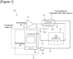
Figure 1 ] is a drawing illustrating a water cooling apparatus (series arrangement) according toembodiment 1. - [
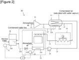
Figure 2 ] is a drawing illustrating a water cooling apparatus according to embodiment 2. - [
Figure 3 ] is a drawing illustrating a water cooling apparatus according to embodiment 3. - [
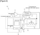
Figure 4 ] is a drawing illustrating a water cooling apparatus (parallel arrangement) according to another embodiment ofembodiment 1. - Several embodiments of the present invention will be described below. The embodiments described below are given as an example of the present disclosure. The present disclosure is in no way limited by the following embodiments, and also includes a number of variants which are implemented within a scope that does not alter the gist of the present disclosure. It should be noted that not all the constituents described below are necessarily essential to the present disclosure. Upstream and downstream are based on a flow direction of a gas stream.
- A water cooling apparatus A1 according to
embodiment 1 will be described with reference toFigure 1 . - The water cooling apparatus A1 comprises a
compressed air cooler 12, a wet-type water cooler 13, a coolingwater pump 14, and a dry-type water cooler 15. - The
compressed air cooler 12 cools the compressed air compressed by theair compressor 11 which takes in atmospheric air containing water. Thecompressed air cooler 12 is provided in a bottom portion with a condensedwater storage portion 12a for storing condensed water produced by the increase in pressure. The compressed air compressed by theair compressor 11 is cooled by the cooling water until reaching a state of water vapour saturation, and condensed water is generated. The cooling water is sent from thestorage portion 131 of the wet-type water cooler 13 by means of the coolingwater pump 14. Thecompressed air cooler 12 causes heat to be exchanged indirectly between the atmospheric air compressed by theair compressor 11 and the cooling water to produce compressed air saturated with water vapour. The water condensed by cooling condenses to form dew on the surface of the heat exchanger and drips down, or the condensed water in the form of mist or droplets floating in the compressed air is separated by a mist separator or the like and is stored in thecompressed air cooler 12. - The wet-
type water cooler 13 includes thestorage portion 131, and the condensed water generated in thecompressed air cooler 12 is introduced into the bottom of the wet-type water cooler 13 as makeup water through the first condensed water line pipe L2 where it accumulates in thestorage portion 131. The wet-type water cooler 13 causes a portion of the cooling water to evaporate, and cools the cooling water using the latent heat of evaporation. In the present embodiment, the water is caused to evaporate by being brought into contact with atmospheric air (natural convection or forced convection), but it is not necessary to release the evaporated water to the atmosphere, and evaporation may be performed under reduced pressure conditions isolated from the atmosphere, or the cooling water may be indirectly cooled by means of a heat exchanger cooled through the evaporation of the water. - The flow
rate regulating valve 121 is provided in the first condensed water line pipe L2, and the condensed water can be sent from thecompressed air cooler 12 to the wet-type water cooler 13 by controlling the opening and closing of the valve. - For example, the flow
rate regulating valve 121 may be opened and closed under timer control, or may be opened and closed on the basis of the level of condensed water in thecompressed air cooler 12, or may be controlled by flow rate control employing a condensed water flowmeter (not shown) disposed in the condensed water line pipe L2. - The cooling
water pump 14 is disposed in the cooling water line pipe L3, and sends the cooling water discharged from thestorage portion 131 of the wet-type water cooler 13 to the cold end of thecompressed air cooler 12 to cool the compressed air by means of the cooling water. - The dry-
type water cooler 15 cools the cooling water discharged from the warm end of thecompressed air cooler 12. Cooling is performed by driving a blower motor M. The dry-type water cooler 15 cools the cooling water by means of indirect heat exchange with air sent from a blower. - The atmospheric air line pipe L1 is a pipe that sends atmospheric air to the
air compressor 11 and sends compressed air from theair compressor 11 to thecompressed air cooler 12. - The first condensed water line pipe L2 is a pipe that sends condensed water from the
storage portion 12a of thecompressed air cooler 12 to the top of the wet-type water cooler 13. - The cooling water line pipe L3 sends cooling water from the
storage portion 131 of the wet-type water cooler 13 to the cold end of thecompressed air cooler 12. Further, the cooling water line pipe L3 is a pipe that sends cooling water from the hot end of thecompressed air cooler 12 to the dry-type water cooler 15 and sends the cooled cooling water to the wet-type water cooler 13. - Compressed air has a wide range of industrial uses, and when
embodiment 1 is employed, water vapour derived from the atmosphere is condensed to obtain condensed water when the compressed air is cooled. Supplying the condensed water to the wet-type water cooler 13 allows some cooling water evaporation loss to be covered, or allows an increase in the load of the wet-type water cooler 13 so as to limit the cooling load of the dry-type water cooler 15, thereby making it possible to reduce the power consumption required by the blower used in the dry-type water cooler 15. - Since the
compressed air cooler 12 can be operated at a pressure higher than that of the cooling water line pipe L3, disposing the flowrate regulating valve 121 in the first condensed water line pipe L2 makes it possible to perform control so as to minimize energy losses resulting from reduced pressure when the condensed water is discharged from thecompressed air cooler 12. - The wet-
type water cooler 13 and the dry-type water cooler 15 are arranged in series inFigures 1 to 3 , but may be arranged in parallel. A parallel arrangement is illustrated inFigure 4 . The cooling water line pipe L3 has a branch pipe L31 that branches off midway along from the warm end of thecompressed air cooler 12 toward the dry-type water cooler 15. The branch pipe L31 is a pipe that sends water from the warm end of thecompressed air cooler 12 to the top of the wet-type water cooler 13. Further, the cooling water cooled by the dry-type water cooler merges with the cooling water line pipe L3 upstream of the coolingwater pump 14. - A water cooling apparatus A2 according to embodiment 2 will be described with reference to
Figure 2 . - The water cooling apparatus A2 comprises a
compressed air cooler 12, a wet-type water cooler 13, a coolingwater pump 14, a dry-type water cooler 15, awater buffer 16, and afirst control unit 18. A description of components that are the same as those inembodiment 1 will be omitted. - Since access of the cooling water apparatus A2 to utilities such as electric power or water resources is not necessarily constant, it is preferable to have a buffer to operate the apparatus stably under any circumstances.
- The
water buffer 16 can store both water supplied from outside the apparatus (industrial water, etc.) and condensed water from the cooler 12. Since the condensed water may contain atmospheric components as impurities, the condensed water may be purified using a purification device or the like, either alone or together with the supplied water. The purification device may be disposed between thewater buffer 16 and the wet-type water cooler 13. - Since the condensed water is derived from atmospheric air, the amount thereof that can be collected is not necessarily stable, and therefore providing the
water buffer 16 enables stable management of the condensed water. - The
water buffer 16 has astorage portion 161. Thewater buffer 16 can be supplied with service water. Further, a first condensed water line pipe L2 is connected from thestorage portion 12a of thecompressed air cooler 12 to thestorage portion 161, and sends the condensed water. - A second condensed water line pipe L21 is a pipe that sends condensed water (makeup water) from the
storage portion 161 of thewater buffer 16 to thestorage portion 131 of the wet-type water cooler 13. - A second flow
rate regulating valve 122 is provided in the second condensed water line pipe L21. The second flowrate regulating valve 122 regulates the flow rate of the condensed water (makeup water). The second flowrate regulating valve 122 may be opened and closed under timer control, or may be opened and closed on the basis of the level of condensed in thestorage portion 161 of thewater buffer 16 and/or the liquid level in thestorage portion 131 of the wet-type water cooler 13, or may be controlled by flow rate control employing a condensed water flowmeter disposed in the second condensed water line pipe L21. - A
first level gauge 22 measures the amount of cooling water in thestorage portion 131 of the wet-type water cooler 13. Asecond level gauge 21 measures the amount of water in thestorage portion 161 of thewater buffer 16. - The
first control unit 18 controls the first flowrate regulating valve 121 and the second flowrate regulating valve 122 on the basis of data from thefirst level gauge 22 and thesecond level gauge 21, to control the amount of condensed water (makeup water) supplied. - The
first control unit 18 may control driving of the coolingwater pump 14. - A water cooling apparatus A3 according to embodiment 3 will be described with reference to
Figure 3 . - The water cooling apparatus A3 comprises a
compressed air cooler 12, a wet-type water cooler 13, a coolingwater pump 14, a dry-type water cooler 15, awater buffer 16, afirst control unit 18, and a second control unit 19. A description of components that are the same as those inembodiments 1 and 2 will be omitted. - The second control unit 19 controls the operation rate of the dry-
type water cooler 15, and more specifically controls a blower, in accordance with an increase or decrease in the cost of electric power. Data relating to the cost of electric power are sent from an external device that stores fluctuations in the cost of electric power. - When the cost of electric power is high, the operating rate of the dry-
type water cooler 15 is reduced. In addition, when the cost of electric power is high, thefirst control unit 18 introduces condensed water from thewater buffer 16 into the wet-type water cooler 13 to adjust the operating rate thereof. - Furthermore, in cases in which the power supply capacity can change depending on the environment, such as solar power generation or wind power generation, it is necessary to adjust the respective loads of the dry-
type water cooler 15 and the wet-type water cooler 13. - For example, control is performed such that the dry-
type water cooler 15 is mainly operated using inexpensive electric power during the day when solar power generation is possible, and the wet-type water cooler 13 load is increased at night as the unit price of electric power rises. - At this time, during the day, the condensed water obtained from the
compressed air cooler 12 is stored in thewater buffer 16, and during the night, the water demand of the wet-type water cooler 13 is met using the water stored in thewater buffer 16. In other words, by using the condensed water under conditions in which the condensed water is most valuable in relation to the price of electric power, the economic efficiency of the cooling water apparatus can be improved. In addition, the apparatus allows renewable energy to be used when available and reduces the demand for electricity at peak periods, thus contributing to a reduction of the risk of overload. - Economic data such as the unit price of electricity are used to determine the operation method of the cooling water apparatus A3, that is, load sharing between the dry-type water cooler 15 (which mainly consumes electric power) and the wet-type water cooler 13 (which mainly consumes water). When the cost of electric power is determined to be low, the dry-
type water cooler 15 is mainly operated and the condensed water is stored in thewater buffer 16, and when the cost of electric power is determined to be high, the dry-type water cooler 15 load is reduced and wet-type water cooler 13 load is increased. - The wet-
type water cooler 13 load can be detected from the loss of water due to evaporation, specifically, from a drop in the water level in thestorage portion 131 of the wet-type water cooler 13, and therefore makeup water (condensed water or a mixture of condensed water and service water) is supplied from thewater buffer 16 such that the water level remains within a control value. - The amount of water (water level) in the
water buffer 16 may be taken into consideration when determining whether to adjust the dry-type water cooler 15 load, and by so doing, even when the water level in thewater buffer 16 drops, the apparatus can be operated such that the cooling water temperature is stable, by increasing thedry water cooler 15 load. - The results of a physical simulation of embodiment 3 are presented.
- A case is considered in which 100,000 Nm3/h of air with inlet conditions of a temperature of 35°C, a relative humidity of 80%, and 1 barA is compressed and cooled using an air compressor with four compression stages to obtain compressed air with outlet conditions of a temperature of 42°C, a relative humidity of 100%, and 10 barA.
- Under the inlet conditions, water contained in the air is 3786 kg/h, but under the outlet conditions, the air is saturated and only 684 kg/h of water exists as water vapour, so the difference of 3102 kg/h can be recovered as condensed water.
- Since the latent heat of vaporization of water is 575 cal/g at 40°C, if the cooling water temperature is 40°C, the cooling water can be cooled by an amount equivalent to the latent heat of vaporization of 1783 Mcal/h with 3102 kg/h of condensed water. The motive power required for a dry-type water cooler may vary depending on a difference between the atmospheric temperature and the cooling water temperature, but generally the smaller the temperature difference, the more airflow is required, and for example, when atmospheric air at 35°C is being blown to obtain cooling water at 40°C, 0.052 kW of electric power are consumed.
- If the abovementioned condensed water is used for water cooling, 1783 Mcal/h x 0.052 kWh/Mcal=93 kW of electric power can be saved.
- We will consider optimization of water cooling with a heat load of 7,400 Mcal/h (corresponding to the cooling demand of the air compressor mentioned above) using a dry-type water cooler and a wet-type water cooler that employs condensed water, for a case in which the cost of electric power differs between day and night.
- Assume that the daytime period is 12 hours and the cost of electric power is 20 yen/kWH, and the night-time period is 12 hours and the cost of electric power is 60 yen/kWH.
- If the condensed water is used continuously in the wet-type cooler regardless of day or night, the dry-type water cooler load is reduced by 93 kW, and 292 kW (= 7400 Mcal/h x 0.052 kWh/Mcal-93 kW) of electric power is used.
- In this case, the cost of electric power per day is 20 yen/kWh x 292 kW x 12 h + 60 yen/kWh x 292 kW x 12 h = 280,320 yen.
- Meanwhile, if only the dry-type water cooler operates during the day and the condensed water is stored, and both the supplied condensed water and the stored condensed water are used at night, the dry-type water cooler load is such that 385 kW of electric power is used during the day, while 199 kW (= 385 kW - 186 kW) of electric power is used at night.
- In this case, the cost of electric power per day is 20 yen/kWh x 385 kW x 12 h + 60 yen/kWh x 199 kW x 12 h = 235,680 yen.
- In other words, this means that by using the condensed water intensively at night when the cost of electric power is high, it is expected that the cost of electric power can be reduced by approximately 16% per day.
- In the present embodiment, the intention is to reduce the electric power and water supply loads required for water cooling by utilizing the condensed water obtained as a result of the compression and cooling of air, but, by adjusting the timing of use of the condensed water in accordance with the power supply capacity that can be generated by utilising renewable energy, and actively utilising the condensed water in particular when power shortages are likely to occur, to reduce power consumption associated with water cooling, the cost of electric power (which implicitly includes the installation costs of a generator and a storage battery enabling stable power generation) can be reduced.
-
- (1) The compressed air generated in
embodiments 1 to 4 may be provided to an air separation apparatus, following a step to remove remaining water and carbon dioxide and cooling. - (2)
Embodiments 1 to 4 are not limited to compressed air, and may be applied to compressed gases such as flue gas, LNG or boil-off gas from an LNG storage tank.
Claims (15)
- Compressed gas cooling apparatus (A1, A2, A3) comprising: a compressor (11) for compressing a gas containing water, a compressed gas cooler (12) for cooling compressed gas compressed by the compressor (11) by indirect heat exchange with cooling water;• a wet-type cooler (13),• a first condensed water pipe (L2) connected to the compressed gas cooler for sending condensed water generated in the compressed gas cooler into the wet-type cooler as makeup water;• a first flow rate regulating valve (121) provided in the first condensed water line pipe to regulate a flow rate of the condensed water.• a cooling water pump (14) connected to send cooling water discharged from the wet-type water cooler to a cold end of the compressed gas cooler to cool the compressed gas by means of the cooling water;• a dry-type water cooler (15) connected to a warm end of the compressed gas cooler for cooling cooling water discharged from the warm end of the compressed gas cooler;
and• means for sending water warmed in the compressed gas cooler to the wet-type cooler to be cooled by direct heat exchange with air in the wet-type cooler. - Apparatus according to Claim 1, wherein the means for sending water warmed in the compressed gas cooler (12) to the wet-type cooler (13) to be cooled by direct heat exchange with air in the wet-type cooler include the dry-type cooler (15) which is connected to the wet-type cooler to send water warmed in the dry-type cooler thereto.
- Apparatus according to Claim 1 wherein the means for sending water warmed in the compressed gas cooler (12) to the wet-type cooler (13) to be cooled by direct heat exchange with air in the wet-type cooler without passing through the dry-type cooler (15), the dry-type being connected to the cooling water pump for sending water to the pump without having been cooled in the wet-type cooler.
- Apparatus according to Claim 1, 2 or 3 including a water buffer (16) for storing the condensed water.
- Apparatus according to Claim 4, including a second condensed water line pipe (L21) that sends condensed water from the water buffer (16) to the wet-type water cooler (13); and a second flow rate regulating valve (122) provided in the second condensed water line pipe to regulate the flow rate of the condensed water.
- Apparatus according to any preceding claim , including a first control unit that controls the first flow rate regulating valve (121) to control the amount of condensed water supplied to the wet-type cooler (13).
- Apparatus according to Claim 4, including a first control unit (18) that controls the second flow rate regulating valve (122) to control the amount of condensed water supplied to the wet-type cooler (13).
- Apparatus according to any preceding including a control unit (19) for controlling an operation rate of the dry-type water cooler (15) in accordance with an increase or decrease in the cost of electric power or with the availability of a renewable energy source.
- Air separation unit including a compressed gas cooling apparatus (A1, A2,A3) according to any preceding claim, and means for separating the air compressed in the compressor and cooled by the apparatus.
- Process for cooling compressed gas wherein:a) a gas containing water is compressed in a compressor and cooled in a compressed gas cooler (12) by indirect heat exchange with cooling water, causing water present in the gas to condense forming condensed water;b) condensed water is sent from the compressed gas cooler to a wet type cooler (13) via a first condensed water pipe (L2) and a first flow rate regulating valve (121) provided in the first condensed water line pipe to regulate a flow rate of the condensed water,c) cooling water warmed in the compressed gas cooler is sent to be cooled in a dry-type cooler (15) and in the wet-type cooler, connected in parallel or in series, the dry-type cooler being upstream of the wet-type cooler if connected in series,d) optionally air is sent to the wet-type cooler to cool the cooling watere) cooled cooling water is removed from the wet-type cooler, pressurised in a pump (14) and sent to a cold end of the compressed gas cooler.
- Process according to Claim 10 wherein cooled cooling water is removed from the dry-type cooler (15), without passing through the wet-type cooler, pressurised in a pump (14) and sent to a cold end of the compressed gas cooler (12).
- Process according to Claim 10 or 11 wherein part of the warmed cooling water is sent from the compressed gas cooler (12) to the dry-type cooler (15) and part of the warmed cooling water is sent from the compressed gas cooler to the wet-type cooler (13).
- Process according to Claim 10 wherein all the warmed cooling water from the compressed gas cooler (12) is sent to be cooled first in the dry type cooler (15) and then in the wet-type cooler (13).
- Process according to any of claims 10 to 13 wherein the dry type cooler (15) uses an air blower to cool the warmed cooling water by indirect heat exchange.
- Process according to any of claims 10 to 14 wherein the wet type cooler (13) cools the warmed cooling water by direct heat exchange with air.
Applications Claiming Priority (1)
| Application Number | Priority Date | Filing Date | Title |
|---|---|---|---|
| JP2023206024A JP7509348B1 (en) | 2023-12-06 | 2023-12-06 | Water cooling system and air separation unit equipped with same |
Publications (2)
| Publication Number | Publication Date |
|---|---|
| EP4567359A2 true EP4567359A2 (en) | 2025-06-11 |
| EP4567359A3 EP4567359A3 (en) | 2025-08-06 |
Family
ID=91671282
Family Applications (1)
| Application Number | Title | Priority Date | Filing Date |
|---|---|---|---|
| EP24216726.0A Withdrawn EP4567359A3 (en) | 2023-12-06 | 2024-12-02 | Compressed gas cooling apparatus and air separation device provided with a compressed gas cooling apparatus |
Country Status (4)
| Country | Link |
|---|---|
| EP (1) | EP4567359A3 (en) |
| JP (1) | JP7509348B1 (en) |
| CN (1) | CN120101421A (en) |
| AU (1) | AU2024227334A1 (en) |
Citations (2)
| Publication number | Priority date | Publication date | Assignee | Title |
|---|---|---|---|---|
| JP2004232925A (en) | 2003-01-29 | 2004-08-19 | Yae Kogyo:Kk | Method and device for manufacturing cool water |
| US20210341222A1 (en) | 2020-04-30 | 2021-11-04 | Air Products And Chemicals, Inc. | Process for Enhanced Closed-Circuit Cooling System |
Family Cites Families (12)
| Publication number | Priority date | Publication date | Assignee | Title |
|---|---|---|---|---|
| JPS5643394Y2 (en) * | 1978-06-17 | 1981-10-12 | ||
| JP3838595B2 (en) * | 1997-06-27 | 2006-10-25 | オリオン機械株式会社 | Water-cooled condenser and air dryer |
| US20030033831A1 (en) * | 2001-08-15 | 2003-02-20 | Davies Brian M. | System and method of cooling |
| US6912859B2 (en) * | 2002-02-12 | 2005-07-05 | Air Liquide Process And Construction, Inc. | Method and apparatus for using a main air compressor to supplement a chill water system |
| FR2844864B3 (en) * | 2003-02-25 | 2005-04-08 | Air Liquide | METHOD AND INSTALLATION FOR VAPORIZATION OF A CRYOGENIC LIQUID |
| JP2007024488A (en) * | 2005-06-16 | 2007-02-01 | Hitachi Metals Ltd | Cooler |
| PT2447479T (en) * | 2010-10-26 | 2016-11-02 | Siemens Ag | Methods for cooling a carrier fluid of a solar power plant and solar power plant |
| US20120180512A1 (en) * | 2011-01-13 | 2012-07-19 | General Electric Company | Water recovery system for a cooling tower |
| CN104511231B (en) * | 2013-09-26 | 2016-08-24 | 宝山钢铁股份有限公司 | A kind of energy-saving cold dryer blood circulation |
| US9995530B2 (en) * | 2016-02-24 | 2018-06-12 | Charles Bliss | Method for the capture of carbon dioxide through cryogenically processing gaseous emissions from fossil-fuel power generation |
| US12247520B2 (en) * | 2020-06-16 | 2025-03-11 | Ge Infrastructure Technology Llc | Wet dry integrated circulation cooling system |
| CN111707054A (en) * | 2020-06-18 | 2020-09-25 | 中冶西北工程技术有限公司 | Air separation cold energy recovery system |
-
2023
- 2023-12-06 JP JP2023206024A patent/JP7509348B1/en active Active
-
2024
- 2024-10-15 AU AU2024227334A patent/AU2024227334A1/en active Pending
- 2024-12-02 EP EP24216726.0A patent/EP4567359A3/en not_active Withdrawn
- 2024-12-02 CN CN202411748898.0A patent/CN120101421A/en active Pending
Patent Citations (2)
| Publication number | Priority date | Publication date | Assignee | Title |
|---|---|---|---|---|
| JP2004232925A (en) | 2003-01-29 | 2004-08-19 | Yae Kogyo:Kk | Method and device for manufacturing cool water |
| US20210341222A1 (en) | 2020-04-30 | 2021-11-04 | Air Products And Chemicals, Inc. | Process for Enhanced Closed-Circuit Cooling System |
Also Published As
| Publication number | Publication date |
|---|---|
| JP7509348B1 (en) | 2024-07-02 |
| EP4567359A3 (en) | 2025-08-06 |
| AU2024227334A1 (en) | 2025-06-26 |
| CN120101421A (en) | 2025-06-06 |
| JP2025091056A (en) | 2025-06-18 |
Similar Documents
| Publication | Publication Date | Title |
|---|---|---|
| AU2022201666B2 (en) | Process and apparatus for compressing hydrogen gas in a centrifugual compressor | |
| EP0651145B1 (en) | Gas turbine inlet air cooling system | |
| US3978663A (en) | Process and apparatus for evaporating and heating liquified natural gas | |
| KR101917750B1 (en) | A refrigeration vehicle having a refrigerator separated from a vehicle engine | |
| US10029799B2 (en) | Air conditioning method and system for aircraft | |
| US20200332709A1 (en) | Cold-heat power generation device | |
| WO2010101356A2 (en) | Boil-off gas treatment apparatus for electric-propelled lng carrier having re-liquefaction function and method thereof | |
| US20140260251A1 (en) | Combined Heat and Power Technology for Natural Gas Liquefaction Plants | |
| CN110651151B (en) | Liquefied gas supply backup system and liquefied gas backup supply method | |
| US20140130521A1 (en) | Configurations and Methods for Ambient Air Vaporizers and Cold Utilization | |
| KR20190142185A (en) | A refrigeration vehicle having a refrigerator separated from a vehicle engine | |
| US20120167618A1 (en) | Use of refrigeration loops to chill inlet air to gas turbine | |
| KR20190072948A (en) | Hybrid propulsion lng carrier using fuel cell | |
| US20250189246A1 (en) | Water cooling system and air separation device provided with same | |
| US20230010823A1 (en) | Water-based, combined cooling and humidification system for a fuel cell system | |
| JP7509348B1 (en) | Water cooling system and air separation unit equipped with same | |
| KR20240028594A (en) | Device | |
| US20190264978A1 (en) | System for treating and cooling a hydrocarbon stream | |
| JP7460974B1 (en) | Nitrogen generator and nitrogen generation method | |
| US20140033732A1 (en) | Method and device for generating electrical energy | |
| GB2632288A (en) | Power unit | |
| AU2022324920A1 (en) | Power-conditioning system, power-conditioning method, and power-conditioning program | |
| KR102433264B1 (en) | gas treatment system and offshore plant having the same | |
| JP5244491B2 (en) | Air separation device | |
| US20140260418A1 (en) | Method to Maximize LNG Plant Capacity in All Seasons |
Legal Events
| Date | Code | Title | Description |
|---|---|---|---|
| PUAI | Public reference made under article 153(3) epc to a published international application that has entered the european phase |
Free format text: ORIGINAL CODE: 0009012 |
|
| STAA | Information on the status of an ep patent application or granted ep patent |
Free format text: STATUS: THE APPLICATION HAS BEEN PUBLISHED |
|
| AK | Designated contracting states |
Kind code of ref document: A2 Designated state(s): AL AT BE BG CH CY CZ DE DK EE ES FI FR GB GR HR HU IE IS IT LI LT LU LV MC ME MK MT NL NO PL PT RO RS SE SI SK SM TR |
|
| PUAL | Search report despatched |
Free format text: ORIGINAL CODE: 0009013 |
|
| AK | Designated contracting states |
Kind code of ref document: A3 Designated state(s): AL AT BE BG CH CY CZ DE DK EE ES FI FR GB GR HR HU IE IS IT LI LT LU LV MC ME MK MT NL NO PL PT RO RS SE SI SK SM TR |
|
| RIC1 | Information provided on ipc code assigned before grant |
Ipc: F25J 3/04 20060101AFI20250701BHEP Ipc: F04D 29/58 20060101ALI20250701BHEP Ipc: F28D 21/00 20060101ALI20250701BHEP |
|
| STAA | Information on the status of an ep patent application or granted ep patent |
Free format text: STATUS: THE APPLICATION HAS BEEN WITHDRAWN |
|
| 18W | Application withdrawn |
Effective date: 20260204 |