EP4567303A1 - Unit - Google Patents
Unit Download PDFInfo
- Publication number
- EP4567303A1 EP4567303A1 EP23849806.7A EP23849806A EP4567303A1 EP 4567303 A1 EP4567303 A1 EP 4567303A1 EP 23849806 A EP23849806 A EP 23849806A EP 4567303 A1 EP4567303 A1 EP 4567303A1
- Authority
- EP
- European Patent Office
- Prior art keywords
- planetary gear
- gear mechanism
- brake
- engagement element
- unit
- Prior art date
- Legal status (The legal status is an assumption and is not a legal conclusion. Google has not performed a legal analysis and makes no representation as to the accuracy of the status listed.)
- Pending
Links
Images



Classifications
-
- F—MECHANICAL ENGINEERING; LIGHTING; HEATING; WEAPONS; BLASTING
- F16—ENGINEERING ELEMENTS AND UNITS; GENERAL MEASURES FOR PRODUCING AND MAINTAINING EFFECTIVE FUNCTIONING OF MACHINES OR INSTALLATIONS; THERMAL INSULATION IN GENERAL
- F16H—GEARING
- F16H3/00—Toothed gearings for conveying rotary motion with variable gear ratio or for reversing rotary motion
- F16H3/44—Toothed gearings for conveying rotary motion with variable gear ratio or for reversing rotary motion using gears having orbital motion
- F16H3/62—Gearings having three or more central gears
- F16H3/66—Gearings having three or more central gears composed of a number of gear trains without drive passing from one train to another
-
- F—MECHANICAL ENGINEERING; LIGHTING; HEATING; WEAPONS; BLASTING
- F16—ENGINEERING ELEMENTS AND UNITS; GENERAL MEASURES FOR PRODUCING AND MAINTAINING EFFECTIVE FUNCTIONING OF MACHINES OR INSTALLATIONS; THERMAL INSULATION IN GENERAL
- F16H—GEARING
- F16H3/00—Toothed gearings for conveying rotary motion with variable gear ratio or for reversing rotary motion
- F16H3/44—Toothed gearings for conveying rotary motion with variable gear ratio or for reversing rotary motion using gears having orbital motion
- F16H3/62—Gearings having three or more central gears
- F16H3/64—Gearings having three or more central gears composed of a number of gear trains, the drive always passing through all the trains, each train having not more than one connection for driving another train
-
- F—MECHANICAL ENGINEERING; LIGHTING; HEATING; WEAPONS; BLASTING
- F16—ENGINEERING ELEMENTS AND UNITS; GENERAL MEASURES FOR PRODUCING AND MAINTAINING EFFECTIVE FUNCTIONING OF MACHINES OR INSTALLATIONS; THERMAL INSULATION IN GENERAL
- F16H—GEARING
- F16H57/00—General details of gearing
- F16H57/08—General details of gearing of gearings with members having orbital motion
- F16H57/10—Braking arrangements
-
- B—PERFORMING OPERATIONS; TRANSPORTING
- B60—VEHICLES IN GENERAL
- B60Y—INDEXING SCHEME RELATING TO ASPECTS CROSS-CUTTING VEHICLE TECHNOLOGY
- B60Y2200/00—Type of vehicle
- B60Y2200/90—Vehicles comprising electric prime movers
- B60Y2200/91—Electric vehicles
-
- F—MECHANICAL ENGINEERING; LIGHTING; HEATING; WEAPONS; BLASTING
- F16—ENGINEERING ELEMENTS AND UNITS; GENERAL MEASURES FOR PRODUCING AND MAINTAINING EFFECTIVE FUNCTIONING OF MACHINES OR INSTALLATIONS; THERMAL INSULATION IN GENERAL
- F16H—GEARING
- F16H61/00—Control functions within control units of change-speed- or reversing-gearings for conveying rotary motion ; Control of exclusively fluid gearing, friction gearing, gearings with endless flexible members or other particular types of gearing
- F16H61/26—Generation or transmission of movements for final actuating mechanisms
- F16H61/28—Generation or transmission of movements for final actuating mechanisms with at least one movement of the final actuating mechanism being caused by a non-mechanical force, e.g. power-assisted
- F16H2061/2892—Generation or transmission of movements for final actuating mechanisms with at least one movement of the final actuating mechanism being caused by a non-mechanical force, e.g. power-assisted other gears, e.g. worm gears, for transmitting rotary motion to the output mechanism
-
- F—MECHANICAL ENGINEERING; LIGHTING; HEATING; WEAPONS; BLASTING
- F16—ENGINEERING ELEMENTS AND UNITS; GENERAL MEASURES FOR PRODUCING AND MAINTAINING EFFECTIVE FUNCTIONING OF MACHINES OR INSTALLATIONS; THERMAL INSULATION IN GENERAL
- F16H—GEARING
- F16H63/00—Control outputs from the control unit to change-speed- or reversing-gearings for conveying rotary motion or to other devices than the final output mechanism
- F16H63/02—Final output mechanisms therefor; Actuating means for the final output mechanisms
- F16H63/30—Constructional features of the final output mechanisms
- F16H63/304—Constructional features of the final output mechanisms the final output mechanisms comprising elements moved by electrical or magnetic force
- F16H2063/3066—Constructional features of the final output mechanisms the final output mechanisms comprising elements moved by electrical or magnetic force using worm gears
-
- F—MECHANICAL ENGINEERING; LIGHTING; HEATING; WEAPONS; BLASTING
- F16—ENGINEERING ELEMENTS AND UNITS; GENERAL MEASURES FOR PRODUCING AND MAINTAINING EFFECTIVE FUNCTIONING OF MACHINES OR INSTALLATIONS; THERMAL INSULATION IN GENERAL
- F16H—GEARING
- F16H2200/00—Transmissions for multiple ratios
- F16H2200/0021—Transmissions for multiple ratios specially adapted for electric vehicles
-
- F—MECHANICAL ENGINEERING; LIGHTING; HEATING; WEAPONS; BLASTING
- F16—ENGINEERING ELEMENTS AND UNITS; GENERAL MEASURES FOR PRODUCING AND MAINTAINING EFFECTIVE FUNCTIONING OF MACHINES OR INSTALLATIONS; THERMAL INSULATION IN GENERAL
- F16H—GEARING
- F16H2200/00—Transmissions for multiple ratios
- F16H2200/003—Transmissions for multiple ratios characterised by the number of forward speeds
- F16H2200/0039—Transmissions for multiple ratios characterised by the number of forward speeds the gear ratios comprising three forward speeds
-
- F—MECHANICAL ENGINEERING; LIGHTING; HEATING; WEAPONS; BLASTING
- F16—ENGINEERING ELEMENTS AND UNITS; GENERAL MEASURES FOR PRODUCING AND MAINTAINING EFFECTIVE FUNCTIONING OF MACHINES OR INSTALLATIONS; THERMAL INSULATION IN GENERAL
- F16H—GEARING
- F16H2200/00—Transmissions for multiple ratios
- F16H2200/20—Transmissions using gears with orbital motion
- F16H2200/2002—Transmissions using gears with orbital motion characterised by the number of sets of orbital gears
- F16H2200/2007—Transmissions using gears with orbital motion characterised by the number of sets of orbital gears with two sets of orbital gears
-
- F—MECHANICAL ENGINEERING; LIGHTING; HEATING; WEAPONS; BLASTING
- F16—ENGINEERING ELEMENTS AND UNITS; GENERAL MEASURES FOR PRODUCING AND MAINTAINING EFFECTIVE FUNCTIONING OF MACHINES OR INSTALLATIONS; THERMAL INSULATION IN GENERAL
- F16H—GEARING
- F16H2200/00—Transmissions for multiple ratios
- F16H2200/20—Transmissions using gears with orbital motion
- F16H2200/203—Transmissions using gears with orbital motion characterised by the engaging friction means not of the freewheel type, e.g. friction clutches or brakes
- F16H2200/2033—Transmissions using gears with orbital motion characterised by the engaging friction means not of the freewheel type, e.g. friction clutches or brakes with one engaging means
-
- F—MECHANICAL ENGINEERING; LIGHTING; HEATING; WEAPONS; BLASTING
- F16—ENGINEERING ELEMENTS AND UNITS; GENERAL MEASURES FOR PRODUCING AND MAINTAINING EFFECTIVE FUNCTIONING OF MACHINES OR INSTALLATIONS; THERMAL INSULATION IN GENERAL
- F16H—GEARING
- F16H2200/00—Transmissions for multiple ratios
- F16H2200/20—Transmissions using gears with orbital motion
- F16H2200/203—Transmissions using gears with orbital motion characterised by the engaging friction means not of the freewheel type, e.g. friction clutches or brakes
- F16H2200/2038—Transmissions using gears with orbital motion characterised by the engaging friction means not of the freewheel type, e.g. friction clutches or brakes with three engaging means
-
- F—MECHANICAL ENGINEERING; LIGHTING; HEATING; WEAPONS; BLASTING
- F16—ENGINEERING ELEMENTS AND UNITS; GENERAL MEASURES FOR PRODUCING AND MAINTAINING EFFECTIVE FUNCTIONING OF MACHINES OR INSTALLATIONS; THERMAL INSULATION IN GENERAL
- F16H—GEARING
- F16H2200/00—Transmissions for multiple ratios
- F16H2200/20—Transmissions using gears with orbital motion
- F16H2200/203—Transmissions using gears with orbital motion characterised by the engaging friction means not of the freewheel type, e.g. friction clutches or brakes
- F16H2200/2064—Transmissions using gears with orbital motion characterised by the engaging friction means not of the freewheel type, e.g. friction clutches or brakes using at least one positive clutch, e.g. dog clutch
-
- F—MECHANICAL ENGINEERING; LIGHTING; HEATING; WEAPONS; BLASTING
- F16—ENGINEERING ELEMENTS AND UNITS; GENERAL MEASURES FOR PRODUCING AND MAINTAINING EFFECTIVE FUNCTIONING OF MACHINES OR INSTALLATIONS; THERMAL INSULATION IN GENERAL
- F16H—GEARING
- F16H2200/00—Transmissions for multiple ratios
- F16H2200/20—Transmissions using gears with orbital motion
- F16H2200/203—Transmissions using gears with orbital motion characterised by the engaging friction means not of the freewheel type, e.g. friction clutches or brakes
- F16H2200/2069—Transmissions using gears with orbital motion characterised by the engaging friction means not of the freewheel type, e.g. friction clutches or brakes using two freewheel mechanism
-
- F—MECHANICAL ENGINEERING; LIGHTING; HEATING; WEAPONS; BLASTING
- F16—ENGINEERING ELEMENTS AND UNITS; GENERAL MEASURES FOR PRODUCING AND MAINTAINING EFFECTIVE FUNCTIONING OF MACHINES OR INSTALLATIONS; THERMAL INSULATION IN GENERAL
- F16H—GEARING
- F16H2200/00—Transmissions for multiple ratios
- F16H2200/20—Transmissions using gears with orbital motion
- F16H2200/2079—Transmissions using gears with orbital motion using freewheel type mechanisms, e.g. freewheel clutches
- F16H2200/2084—Transmissions using gears with orbital motion using freewheel type mechanisms, e.g. freewheel clutches two freewheel mechanisms
-
- F—MECHANICAL ENGINEERING; LIGHTING; HEATING; WEAPONS; BLASTING
- F16—ENGINEERING ELEMENTS AND UNITS; GENERAL MEASURES FOR PRODUCING AND MAINTAINING EFFECTIVE FUNCTIONING OF MACHINES OR INSTALLATIONS; THERMAL INSULATION IN GENERAL
- F16H—GEARING
- F16H2200/00—Transmissions for multiple ratios
- F16H2200/20—Transmissions using gears with orbital motion
- F16H2200/2094—Transmissions using gears with orbital motion using positive clutches, e.g. dog clutches
-
- F—MECHANICAL ENGINEERING; LIGHTING; HEATING; WEAPONS; BLASTING
- F16—ENGINEERING ELEMENTS AND UNITS; GENERAL MEASURES FOR PRODUCING AND MAINTAINING EFFECTIVE FUNCTIONING OF MACHINES OR INSTALLATIONS; THERMAL INSULATION IN GENERAL
- F16H—GEARING
- F16H63/00—Control outputs from the control unit to change-speed- or reversing-gearings for conveying rotary motion or to other devices than the final output mechanism
- F16H63/02—Final output mechanisms therefor; Actuating means for the final output mechanisms
- F16H63/04—Final output mechanisms therefor; Actuating means for the final output mechanisms a single final output mechanism being moved by a single final actuating mechanism
-
- F—MECHANICAL ENGINEERING; LIGHTING; HEATING; WEAPONS; BLASTING
- F16—ENGINEERING ELEMENTS AND UNITS; GENERAL MEASURES FOR PRODUCING AND MAINTAINING EFFECTIVE FUNCTIONING OF MACHINES OR INSTALLATIONS; THERMAL INSULATION IN GENERAL
- F16H—GEARING
- F16H63/00—Control outputs from the control unit to change-speed- or reversing-gearings for conveying rotary motion or to other devices than the final output mechanism
- F16H63/02—Final output mechanisms therefor; Actuating means for the final output mechanisms
- F16H63/08—Multiple final output mechanisms being moved by a single common final actuating mechanism
- F16H63/10—Multiple final output mechanisms being moved by a single common final actuating mechanism the final actuating mechanism having a series of independent ways of movement, each way of movement being associated with only one final output mechanism
-
- F—MECHANICAL ENGINEERING; LIGHTING; HEATING; WEAPONS; BLASTING
- F16—ENGINEERING ELEMENTS AND UNITS; GENERAL MEASURES FOR PRODUCING AND MAINTAINING EFFECTIVE FUNCTIONING OF MACHINES OR INSTALLATIONS; THERMAL INSULATION IN GENERAL
- F16H—GEARING
- F16H63/00—Control outputs from the control unit to change-speed- or reversing-gearings for conveying rotary motion or to other devices than the final output mechanism
- F16H63/02—Final output mechanisms therefor; Actuating means for the final output mechanisms
- F16H63/30—Constructional features of the final output mechanisms
- F16H63/304—Constructional features of the final output mechanisms the final output mechanisms comprising elements moved by electrical or magnetic force
- F16H63/3043—Constructional features of the final output mechanisms the final output mechanisms comprising elements moved by electrical or magnetic force comprising friction clutches or brakes
-
- Y—GENERAL TAGGING OF NEW TECHNOLOGICAL DEVELOPMENTS; GENERAL TAGGING OF CROSS-SECTIONAL TECHNOLOGIES SPANNING OVER SEVERAL SECTIONS OF THE IPC; TECHNICAL SUBJECTS COVERED BY FORMER USPC CROSS-REFERENCE ART COLLECTIONS [XRACs] AND DIGESTS
- Y02—TECHNOLOGIES OR APPLICATIONS FOR MITIGATION OR ADAPTATION AGAINST CLIMATE CHANGE
- Y02T—CLIMATE CHANGE MITIGATION TECHNOLOGIES RELATED TO TRANSPORTATION
- Y02T10/00—Road transport of goods or passengers
- Y02T10/60—Other road transportation technologies with climate change mitigation effect
- Y02T10/62—Hybrid vehicles
Definitions
- the present invention relates to a unit.
- Patent Document 1 discloses a vehicle drive device in which a rotating electrical machine and a transmission are disposed on a first shaft, and a differential gear device is disposed on a second shaft.
- a transmission gear mechanism of the transmission includes a first planetary gear mechanism including a first one-way clutch and a second planetary gear mechanism including a second one-way clutch.
- Each of the first one-way clutch and the second one-way clutch is a selectable one-way clutch configured to be switchable between a one-direction restriction state in which rotation in one direction is restricted, a bi-directional restriction state in which rotation in two directions is restricted, and a released state in which rotation in two directions is allowed.
- Patent Document 1 JP 2020-175707 A
- a power transmission mechanism of a unit is configured by using a plurality of planetary gear mechanisms, it is desirable to realize an efficient layout in the unit and to enhance the layout of the unit.
- the present invention has been made in view of such a problem, and an object thereof is to improve the layout property of the unit.
- a unit includes a first planetary gear mechanism, a second planetary gear mechanism, a first engagement element connected to the first planetary gear mechanism, a second engagement element connected to the second planetary gear mechanism, and an actuator configured to drive at least one of the first engagement element and the second engagement element.
- the first engagement element has a portion overlapping the second planetary gear mechanism when viewed in the radial direction.
- the second engagement element has a portion overlapping the second planetary gear mechanism when viewed in the radial direction.
- the first planetary gear mechanism has a portion overlapping the second planetary gear mechanism when viewed in an axial direction.
- the actuator has a portion interposed between the first engagement element and the second engagement element.
- an axial dimension can be reduced by overlapping each of the engagement elements with each of the corresponding planetary gear mechanisms in the radial direction, thereby improving the layout of the unit.
- a clearance is required to prevent the two engagement elements from interfering with each other, and thus the layout of the unit can be further improved by effectively utilizing a space.
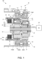
- FIG. 1 is a schematic configuration diagram of a unit 100 according to the present embodiment.
- FIG. 2 is a skeleton diagram of the unit 100.
- the unit can also be referred to as, for example, a motor unit (a unit including at least a motor) or a power transmission device (a device including at least a power transmission mechanism).
- the motor is a rotating electrical machine having an electric motor function and/or a generator function (at least one of the electric motor function and the generator function).
- the power transmission mechanism is, for example, a gear mechanism and/or a differential gear mechanism.
- the device (unit) including the motor and the power transmission mechanism is included in concepts of both the motor unit and the power transmission device.
- the unit 100 includes a housing 10 and a transmission mechanism 20.
- the unit 100 is mounted on a vehicle, which is an electric vehicle.
- the power from a MG 40 is input to the unit 100.
- the MG 40 is a rotating electrical machine that functions as a motor generator, and the unit 100 may further include the MG 40.
- the housing 10 accommodates the transmission mechanism 20.
- the transmission mechanism 20 includes a case 21, a rotary shaft 22, a first planetary gear mechanism PGM1, a second planetary gear mechanism PGM2, a first brake B1, a second brake B2, and a clutch CL.
- the case 21 has a cylindrical shape and is fixed to an inner periphery of the housing 10.
- the first planetary gear mechanism PGM1 is provided via the first brake B1
- the second planetary gear mechanism PGM2 is provided via the second brake B2.
- the rotary shaft 22 is connected to the MG 40, and is rotated by power from the MG 40.
- An extending direction of the rotary shaft 22 corresponds to an axial direction of the unit 100, and the axial direction means an axial direction of the rotary shaft of a component (for example, the motor, the gear mechanism, and the differential gear mechanism) that constitutes the unit.
- a component for example, the motor, the gear mechanism, and the differential gear mechanism
- the first planetary gear mechanism PGM1 includes a first sun gear S1, a first carrier C1, a first ring gear R1, and a first pinion gear P1.
- the first sun gear S1 is coaxially fixed to the rotary shaft 22.
- the first carrier C1 rotatably supports the first pinion gear P1.
- the first pinion gear P1 meshes with both the first sun gear S1 and the first ring gear R1.
- the second planetary gear mechanism PGM2 is disposed side by side with the first planetary gear mechanism PGM1 in the axial direction. Accordingly, the first planetary gear mechanism PGM1 has a portion overlapping the second planetary gear mechanism PGM2 when viewed in the axial direction.
- overlap when viewed in a predetermined direction including a radial direction and an axial direction means overlapping in the predetermined direction, and means that a plurality of elements are disposed in the predetermined direction. Therefore, when a drawing illustrates that a plurality of elements are aligned in a predetermined direction, it may be assumed that the specification contains a sentence explaining that the plurality of elements overlap when viewed in the predetermined direction.
- the second planetary gear mechanism PGM2 is provided on a side away from the MG 40 with respect to the first planetary gear mechanism PGM1.
- the second carrier C2 is formed integrally with the first ring gear R1 to be connected to the first ring gear R1.
- the second carrier C2 constitutes an output element of the second planetary gear mechanism PGM2.
- the first carrier C1 constitutes an output element of the first planetary gear mechanism PGM1, and constitutes an output element of the entire transmission mechanism 20 by constituting an output element of the entire first planetary gear mechanism PGM1 and second planetary gear mechanism PGM2.
- the first brake B1 is provided on an outer periphery of the first ring gear R1 and is connected to the first planetary gear mechanism PGM1.
- the second brake B2 is provided on an outer periphery of the second ring gear R2 and is connected to the second planetary gear mechanism PGM2. Accordingly, the first brake B1 has a portion overlapping the first planetary gear mechanism PGM1 when viewed in the radial direction, and the second brake B2 has a portion overlapping the second planetary gear mechanism PGM2 when viewed in the radial direction.
- the first brake B1 and the second brake B2 are meshing engagement elements, and have a meshing engagement structure.
- the first brake B1 When the first brake B1 is engaged, the first ring gear R1 is fixed to the case 21 together with the second carrier C2. As a result, the first ring gear R1 is fixed to the housing 10 together with the second carrier C2.
- the second ring gear R2 When the second brake B2 is engaged, the second ring gear R2 is fixed to the case 21. As a result, the second ring gear R2 is fixed to the housing 10.
- the first brake B1 corresponds to a first engagement element
- the second brake B2 corresponds to a second engagement element.
- the clutch CL is disposed side by side with the second planetary gear mechanism PGM2 in the axial direction from a side away from the MG 40.
- the clutch CL is provided for the rotary shaft 22 and the second carrier C2, and connects and disconnects the rotary shaft 22 and the second carrier C2.
- the clutch CL is a friction engagement element and is a multi-plate clutch.
- the clutch CL is, for example, an electric clutch, and includes a hub 23, a drum 24, a plurality of drive plates 25, a plurality of driven plates 26, and a piston 27.
- the hub 23 is coaxially fixed to the rotary shaft 22.
- the hub 23 includes an inner cylindrical portion 23a, an outer cylindrical portion 23b, and a bottom wall portion 23c connecting the inner cylindrical portion 23a and the outer cylindrical portion 23b, and is coaxially fixed to the rotary shaft 22 by the inner cylindrical portion 23a.
- the drum 24 includes a cylindrical portion 24a and a bottom wall portion 24b, and is provided coaxially with the rotary shaft 22.
- the drum 24 opens in a direction away from the MG 40.
- the hub 23 is accommodated in the drum 24, and an outer periphery of the outer cylindrical portion 23b of the hub 23 faces an inner periphery of the cylindrical portion 24a of the drum 24.
- the drum 24 is fixed to the second carrier C2 by the ring-shaped bottom wall portion 24b.
- the plurality of drive plates 25 are provided on the hub 23.
- the plurality of drive plates 25 have a ring shape and are provided to be slidable in the axial direction on the outer periphery of the outer cylindrical portion 23b.
- the plurality of driven plates 26 are provided on the drum 24.
- the plurality of driven plates 26 have a ring shape and are provided to be slidable in the axial direction on the inner periphery of the cylindrical portion 24a.
- the plurality of drive plates 25 and the plurality of driven plates 26 are alternately arranged one by one in the axial direction.
- the piston 27 is provided in the drum 24.
- the piston 27 is slidably provided at an inner periphery of the opening of the drum 24.
- the piston 27 is, for example, an electric piston driven by an electric actuator of the clutch CL, and moves in an engagement direction of the clutch CL (a rightward direction in FIG. 1 ) and a disengagement direction (a leftward direction in FIG. 1 ) to engage and disengage the plurality of drive plates 25 and the plurality of driven plates 26.
- a gear position is formed as follows in accordance with an engaged released state of the clutch CL, the first brake B1, and the second brake B2.
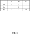
- FIG. 3 is a diagram showing a fastening table of the transmission mechanism 20.
- the transmission mechanism 20 is configured as a three-stage transmission mechanism having three shift speeds of 1st, 2nd, and 3rd, that is, a first-speed, a second-speed, and a third-speed.
- the first-speed is achieved by engaging the first brake B1 and releasing the second brake B2 and the clutch CL.
- the second-speed is achieved by engaging the second brake B2 and releasing the first brake B1 and the clutch CL.
- the third-speed is achieved by engaging the clutch CL and releasing the first brake B1 and the second brake B2.
- the unit 100 further includes a drive device 30.
- the drive device 30 is a drive device for the first brake B1 and the second brake B2, and includes an actuator 31 and a worm wheel 32.
- the actuator 31 is schematically shown by a two-dot chain line.
- the actuator 31 is an electric motor and includes a worm gear 311.
- the worm gear 311 constitutes a rotary shaft of the actuator 31 and meshes with the worm wheel 32.
- a worm shaft of the worm gear 311 and a central axis of the worm wheel 32 are orthogonal to each other, and the worm wheel 32 is provided to be rotatable about an axis of the unit 100 by the power from the actuator 31. Accordingly, a longitudinal direction of the worm gear 311, which is a worm axial direction, intersects the axial direction of the unit 100.
- the worm gear 311 is provided between the first brake B1 and the second brake B2 in the axial direction of the unit 100. Accordingly, the actuator 31 has a portion interposed between the first brake B1 and the second brake B2. In the actuator 31, the worm gear 311 has such a portion.
- the worm wheel 32 is provided between the first planetary gear mechanism PGM1 and the second planetary gear mechanism PGM2 in the axial direction of the unit 100.
- the first brake B1 includes a first switching mechanism SWM1
- the second brake B2 includes a second switching mechanism SWM2.
- the first switching mechanism SWM1 switches an engagement state of the first brake B1
- the second switching mechanism SWM2 switches an engagement state of the second brake B2.
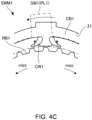
- FIGS. 4A to 4C are diagrams illustrating the switching mechanism SWM.
- FIG. 4A illustrates the first switching mechanism SWM1 in a bi-directional restriction state.
- FIG. 4B illustrates the first switching mechanism SWM1 in one-direction restriction state.
- FIG. 4C illustrates the first switching mechanism SWM1 in a released state.
- the first switching mechanism SWM1 is described as an example of the switching mechanism SWM, and the same applies to the second switching mechanism SWM2.
- the first switching mechanism SWM1 includes a first fixed side member CB1, a first rotational side member RB1, first claws CW1, and a first switching unit SW1.
- the first fixed side member CB1 has a ring shape and is fixed to an inner periphery of the case 21.
- the first claws CW1 are engagement portions, and are provided on portions of the first fixed side member CB1 protruding radially inward. A plurality of portions are provided along a circumferential direction, and two first claws CW1 are provided as one set of claws on the portions. In one set of claws, the first claws CW1 are provided opposite to each other so as to correspond to the two rotation directions.
- Each of the first claws CW1 has a structure in which a radially inner tip end portion rotates about a radially outer base end portion.
- the first claw CW1 is switched between a lock position where rotation of the first ring gear R1 is locked and a free position where the first ring gear R1 is free, and is biased to the lock position by a spring serving as a biasing member. Accordingly, in the state shown in FIG. 4A , each of the first claws CW1 is pressed to the lock position by a spring.
- the first rotational side member RB1 is fixed to the outer periphery of the first ring gear R1.
- the first rotational side member RB1 has a ring shape, and includes engagement portions formed of a plurality of convex portions provided at equal intervals in the circumferential direction.
- the first claws CW1 are engaged with the engagement portions, and constitute a meshing engagement structure together with the engagement portions.
- the first claws CW1 prevent the first ring gear R1 from rotating in one rotation direction, and allows the first ring gear R1 to rotate in the other rotation direction.
- the first claw CW1 on the left side of the left and right one set of claws in the drawing prevents the first ring gear R1 from rotating in the rightward direction in the drawing without the tip end portion escaping to the outside in the radial direction, and allows the first ring gear R1 to rotate in the leftward direction by the tip end portion escaping to the outside in the radial direction.
- the first claw CW1 on the right side prevents the first ring gear R1 from rotating in the leftward direction, and allows the first ring gear R1 to rotate in the rightward direction.
- the bi-directional restriction state illustrated in FIG. 4A the rotation of the first ring gear R1 in the leftward and rightward directions is restricted. Accordingly, as the first ring gear R1 rotates in two directions, the first brake B1 is in an engaged state.
- the first switching unit SW1 includes a first switching plate PL1 and switches a position of the first claw CW1.
- the first switching plate PL1 of the first switching unit SW1 is indicated by a two-dot chain line.
- the first switching plate PL1 has a ring shape and is movable in the circumferential direction.
- the first switching plate PL1 has a position corresponding to the bi-directional restriction state illustrated in FIG. 4A , a position corresponding to the one-direction restriction state illustrated in FIG. 4B , and a position corresponding to the released state illustrated in FIG. 4C .
- the first switching plate PL1 is provided on the worm wheel 32 and rotates together with the worm wheel 32. Accordingly, the first switching plate PL1 is driven in the circumferential direction by the actuator 31, and a position of the first switching plate PL1 is switched accordingly.
- the first switching plate PL1 when the first switching plate PL1 is rotationally driven to a fixed position on the right side from the state illustrated in FIG. 4A , the position of the first switching plate PL1 is switched to the position corresponding to the one-direction restriction state illustrated in FIG. 4B .
- the first switching unit SW1 switches a position of the first claw CW1 on the left side to the free position by pressing the tip end portion of the first nail CW1 on the left side radially outward against a biasing force of the spring.
- the first claw CW1 on the right side is disengaged from the engagement portion of the first rotational side member RB1, and the rotation of the first ring gear R1 in the rightward direction becomes free.
- the first claw CW1 on the right side remains engaged with the engagement portion, and the rotation of the first ring gear R1 in the leftward direction is locked. Therefore, in this case, the first brake B1 is in the released state with respect to the rotation of the first ring gear R1 in the rightward direction, and is in the engaged state with respect to the rotation of the first ring gear R1 in the leftward direction.
- the first switching plate PL1 When the first switching plate PL1 is rotationally driven to a fixed position on the left side from the state illustrated in FIG. 4A , the position of the first switching plate PL1 is switched to the position corresponding to the released state illustrated in FIG. 4C . At this time, the first switching unit SW1 switches the positions of the left and right first claws CW1 to the free position by pressing the tip end portions of both the left and right first claws CW1 radially outward against the biasing force of the spring. As a result, the rotation of the first ring gear R1 in the leftward and rightward directions becomes free.
- the actuator 31 drives the first brake B1 by driving the first switching plate PL1.
- the actuator 31 can also drive the second brake B2 in the same manner as the first brake B1.
- the unit 100 includes the first planetary gear mechanism PGM1, the second planetary gear mechanism PGM2, the first brake B1 connected to the first planetary gear mechanism PGM1, the second brake B2 connected to the second planetary gear mechanism PGM2, and the actuator 31 that drives the first brake B1 and the second brake B2.
- the first brake B1 has a portion overlapping the first planetary gear mechanism PGM1 when viewed in the radial direction.
- the second brake B2 has a portion overlapping the second planetary gear mechanism PGM2 when viewed in the radial direction.
- the first planetary gear mechanism PGM1 has a portion overlapping the second planetary gear mechanism PGM2 when viewed in the axial direction.
- the actuator 31 has a portion interposed between the first brake B1 and the second brake B2.
- an axial dimension can be reduced by overlapping each of each of the first brake B1 and the second brake B2 with each of the corresponding planetary gear mechanisms of the first planetary gear mechanism PGM1 and the second planetary gear mechanism PGM2 in the radial direction. Therefore, the layout of the unit 100 is improved. In this case, a clearance is required to prevent the first brake B1 and the second brake B2 from interfering with each other, and the layout of the unit 100 can be further improved by effectively utilizing a space.
- the actuator 31 may be configured to drive the first brake B1 or the second brake B2. In this case, the same functions and effects can also be obtained.
- the actuator 31 drives both the first brake B1 and the second brake B2. According to such a configuration, the number of components can be reduced by sharing the actuator 31 between the first brake B1 and the second brake B2, and the layout of the unit 100 can be improved by reducing the number of components.
- the actuator 31 includes the worm gear 311.
- the worm gear 311 has a portion interposed between the first brake B1 and the second brake B2, and a longitudinal direction of the worm gear 311 intersects the axial direction of the unit 100. According to such a configuration, when the worm gear 311 of the actuator 31 is interposed between the first brake B1 and the second brake B2, the axial dimension of the unit 100 can be reduced by intersecting the longitudinal direction with the axial direction.
Landscapes
- Engineering & Computer Science (AREA)
- General Engineering & Computer Science (AREA)
- Mechanical Engineering (AREA)
- Structure Of Transmissions (AREA)
Abstract
Description
- The present invention relates to a unit.
-
Patent Document 1 discloses a vehicle drive device in which a rotating electrical machine and a transmission are disposed on a first shaft, and a differential gear device is disposed on a second shaft. A transmission gear mechanism of the transmission includes a first planetary gear mechanism including a first one-way clutch and a second planetary gear mechanism including a second one-way clutch. Each of the first one-way clutch and the second one-way clutch is a selectable one-way clutch configured to be switchable between a one-direction restriction state in which rotation in one direction is restricted, a bi-directional restriction state in which rotation in two directions is restricted, and a released state in which rotation in two directions is allowed. - Patent Document 1:
JP 2020-175707 A - In a case where a power transmission mechanism of a unit is configured by using a plurality of planetary gear mechanisms, it is desirable to realize an efficient layout in the unit and to enhance the layout of the unit.
- The present invention has been made in view of such a problem, and an object thereof is to improve the layout property of the unit.
- A unit according to an aspect of the present invention includes a first planetary gear mechanism, a second planetary gear mechanism, a first engagement element connected to the first planetary gear mechanism, a second engagement element connected to the second planetary gear mechanism, and an actuator configured to drive at least one of the first engagement element and the second engagement element. The first engagement element has a portion overlapping the second planetary gear mechanism when viewed in the radial direction. The second engagement element has a portion overlapping the second planetary gear mechanism when viewed in the radial direction. The first planetary gear mechanism has a portion overlapping the second planetary gear mechanism when viewed in an axial direction. The actuator has a portion interposed between the first engagement element and the second engagement element.
- According to this aspect, an axial dimension can be reduced by overlapping each of the engagement elements with each of the corresponding planetary gear mechanisms in the radial direction, thereby improving the layout of the unit. At this time, a clearance is required to prevent the two engagement elements from interfering with each other, and thus the layout of the unit can be further improved by effectively utilizing a space.
-
- [
FIG. 1] FIG. 1 is a schematic configuration diagram of a unit according to the present embodiment. - [
FIG. 2] FIG. 2 is a skeleton diagram of the unit. - [
FIG. 3] FIG. 3 is a diagram showing a fastening table of a transmission mechanism. - [
FIG. 4A] FIG. 4A is a first diagram illustrating a switching mechanism. - [
FIG. 4B] FIG. 4B is a second diagram illustrating the switching mechanism. - [
FIG. 4C] FIG. 4C is a third diagram illustrating the switching mechanism. - Hereinafter, embodiments of the present invention will be described with reference to the accompanying drawings.
-
FIG. 1 is a schematic configuration diagram of aunit 100 according to the present embodiment.FIG. 2 is a skeleton diagram of theunit 100. - Regarding the term of unit, the unit can also be referred to as, for example, a motor unit (a unit including at least a motor) or a power transmission device (a device including at least a power transmission mechanism). The motor is a rotating electrical machine having an electric motor function and/or a generator function (at least one of the electric motor function and the generator function). The power transmission mechanism is, for example, a gear mechanism and/or a differential gear mechanism. The device (unit) including the motor and the power transmission mechanism is included in concepts of both the motor unit and the power transmission device.
- As shown in
FIG. 1 , theunit 100 includes ahousing 10 and atransmission mechanism 20. Theunit 100 is mounted on a vehicle, which is an electric vehicle. The power from a MG 40 is input to theunit 100. The MG 40 is a rotating electrical machine that functions as a motor generator, and theunit 100 may further include the MG 40. - The
housing 10 accommodates thetransmission mechanism 20. Thetransmission mechanism 20 includes acase 21, arotary shaft 22, a first planetary gear mechanism PGM1, a second planetary gear mechanism PGM2, a first brake B1, a second brake B2, and a clutch CL. Thecase 21 has a cylindrical shape and is fixed to an inner periphery of thehousing 10. In thecase 21, the first planetary gear mechanism PGM1 is provided via the first brake B1, and the second planetary gear mechanism PGM2 is provided via the second brake B2. Therotary shaft 22 is connected to the MG 40, and is rotated by power from the MG 40. An extending direction of therotary shaft 22 corresponds to an axial direction of theunit 100, and the axial direction means an axial direction of the rotary shaft of a component (for example, the motor, the gear mechanism, and the differential gear mechanism) that constitutes the unit. - The first planetary gear mechanism PGM1 includes a first sun gear S1, a first carrier C1, a first ring gear R1, and a first pinion gear P1. The first sun gear S1 is coaxially fixed to the
rotary shaft 22. The first carrier C1 rotatably supports the first pinion gear P1. The first pinion gear P1 meshes with both the first sun gear S1 and the first ring gear R1. This also applies to the second planetary gear mechanism PGM2 including a second sun gear S2, a second carrier C2, a second ring gear R2, and a second pinion gear P2. - The second planetary gear mechanism PGM2 is disposed side by side with the first planetary gear mechanism PGM1 in the axial direction. Accordingly, the first planetary gear mechanism PGM1 has a portion overlapping the second planetary gear mechanism PGM2 when viewed in the axial direction. The expression "overlap when viewed in a predetermined direction including a radial direction and an axial direction" means overlapping in the predetermined direction, and means that a plurality of elements are disposed in the predetermined direction. Therefore, when a drawing illustrates that a plurality of elements are aligned in a predetermined direction, it may be assumed that the specification contains a sentence explaining that the plurality of elements overlap when viewed in the predetermined direction.
- The second planetary gear mechanism PGM2 is provided on a side away from the MG 40 with respect to the first planetary gear mechanism PGM1. The second carrier C2 is formed integrally with the first ring gear R1 to be connected to the first ring gear R1. The second carrier C2 constitutes an output element of the second planetary gear mechanism PGM2. On the other hand, the first carrier C1 constitutes an output element of the first planetary gear mechanism PGM1, and constitutes an output element of the
entire transmission mechanism 20 by constituting an output element of the entire first planetary gear mechanism PGM1 and second planetary gear mechanism PGM2. - The first brake B1 is provided on an outer periphery of the first ring gear R1 and is connected to the first planetary gear mechanism PGM1. The second brake B2 is provided on an outer periphery of the second ring gear R2 and is connected to the second planetary gear mechanism PGM2. Accordingly, the first brake B1 has a portion overlapping the first planetary gear mechanism PGM1 when viewed in the radial direction, and the second brake B2 has a portion overlapping the second planetary gear mechanism PGM2 when viewed in the radial direction.
- The first brake B1 and the second brake B2 are meshing engagement elements, and have a meshing engagement structure. When the first brake B1 is engaged, the first ring gear R1 is fixed to the
case 21 together with the second carrier C2. As a result, the first ring gear R1 is fixed to thehousing 10 together with the second carrier C2. When the second brake B2 is engaged, the second ring gear R2 is fixed to thecase 21. As a result, the second ring gear R2 is fixed to thehousing 10. The first brake B1 corresponds to a first engagement element, and the second brake B2 corresponds to a second engagement element. - The clutch CL is disposed side by side with the second planetary gear mechanism PGM2 in the axial direction from a side away from the
MG 40. The clutch CL is provided for therotary shaft 22 and the second carrier C2, and connects and disconnects therotary shaft 22 and the second carrier C2. The clutch CL is a friction engagement element and is a multi-plate clutch. The clutch CL is, for example, an electric clutch, and includes ahub 23, adrum 24, a plurality ofdrive plates 25, a plurality of drivenplates 26, and apiston 27. - The
hub 23 is coaxially fixed to therotary shaft 22. Thehub 23 includes an innercylindrical portion 23a, an outercylindrical portion 23b, and abottom wall portion 23c connecting the innercylindrical portion 23a and the outercylindrical portion 23b, and is coaxially fixed to therotary shaft 22 by the innercylindrical portion 23a. Thedrum 24 includes acylindrical portion 24a and abottom wall portion 24b, and is provided coaxially with therotary shaft 22. Thedrum 24 opens in a direction away from theMG 40. Thehub 23 is accommodated in thedrum 24, and an outer periphery of the outercylindrical portion 23b of thehub 23 faces an inner periphery of thecylindrical portion 24a of thedrum 24. Thedrum 24 is fixed to the second carrier C2 by the ring-shapedbottom wall portion 24b. - The plurality of
drive plates 25 are provided on thehub 23. The plurality ofdrive plates 25 have a ring shape and are provided to be slidable in the axial direction on the outer periphery of the outercylindrical portion 23b. The plurality of drivenplates 26 are provided on thedrum 24. The plurality of drivenplates 26 have a ring shape and are provided to be slidable in the axial direction on the inner periphery of thecylindrical portion 24a. The plurality ofdrive plates 25 and the plurality of drivenplates 26 are alternately arranged one by one in the axial direction. - The
piston 27 is provided in thedrum 24. Thepiston 27 is slidably provided at an inner periphery of the opening of thedrum 24. Thepiston 27 is, for example, an electric piston driven by an electric actuator of the clutch CL, and moves in an engagement direction of the clutch CL (a rightward direction inFIG. 1 ) and a disengagement direction (a leftward direction inFIG. 1 ) to engage and disengage the plurality ofdrive plates 25 and the plurality of drivenplates 26. - When the plurality of
drive plates 25 and the plurality of drivenplates 26 are pressed and engaged with thepiston 27 in the engagement direction, the clutch CL is brought into an engagement state. As a result, therotary shaft 22 and the second carrier C2 are connected via the clutch CL. When thepiston 27 is moved in the disengagement direction from this state and the plurality ofdrive plates 25 and the plurality of drivenplates 26 are not engaged with each other, the clutch CL enters a disengagement state. As a result, therotary shaft 22 and the second carrier C2 are disconnected from each other via the clutch CL. In thetransmission mechanism 20, a gear position is formed as follows in accordance with an engaged released state of the clutch CL, the first brake B1, and the second brake B2. -
FIG. 3 is a diagram showing a fastening table of thetransmission mechanism 20. As shown inFIG. 3 , thetransmission mechanism 20 is configured as a three-stage transmission mechanism having three shift speeds of 1st, 2nd, and 3rd, that is, a first-speed, a second-speed, and a third-speed. The first-speed is achieved by engaging the first brake B1 and releasing the second brake B2 and the clutch CL. The second-speed is achieved by engaging the second brake B2 and releasing the first brake B1 and the clutch CL. The third-speed is achieved by engaging the clutch CL and releasing the first brake B1 and the second brake B2. - Returning to
FIG. 1 , theunit 100 further includes adrive device 30. Thedrive device 30 is a drive device for the first brake B1 and the second brake B2, and includes anactuator 31 and aworm wheel 32. InFIG. 1 , theactuator 31 is schematically shown by a two-dot chain line. - The
actuator 31 is an electric motor and includes aworm gear 311. Theworm gear 311 constitutes a rotary shaft of theactuator 31 and meshes with theworm wheel 32. A worm shaft of theworm gear 311 and a central axis of theworm wheel 32 are orthogonal to each other, and theworm wheel 32 is provided to be rotatable about an axis of theunit 100 by the power from theactuator 31. Accordingly, a longitudinal direction of theworm gear 311, which is a worm axial direction, intersects the axial direction of theunit 100. - The
worm gear 311 is provided between the first brake B1 and the second brake B2 in the axial direction of theunit 100. Accordingly, theactuator 31 has a portion interposed between the first brake B1 and the second brake B2. In theactuator 31, theworm gear 311 has such a portion. Theworm wheel 32 is provided between the first planetary gear mechanism PGM1 and the second planetary gear mechanism PGM2 in the axial direction of theunit 100. - The first brake B1 includes a first switching mechanism SWM1, and the second brake B2 includes a second switching mechanism SWM2. The first switching mechanism SWM1 switches an engagement state of the first brake B1, and the second switching mechanism SWM2 switches an engagement state of the second brake B2.
-
FIGS. 4A to 4C are diagrams illustrating the switching mechanism SWM.FIG. 4A illustrates the first switching mechanism SWM1 in a bi-directional restriction state.FIG. 4B illustrates the first switching mechanism SWM1 in one-direction restriction state.FIG. 4C illustrates the first switching mechanism SWM1 in a released state. InFIGS. 4A to 4C , the first switching mechanism SWM1 is described as an example of the switching mechanism SWM, and the same applies to the second switching mechanism SWM2. - The first switching mechanism SWM1 includes a first fixed side member CB1, a first rotational side member RB1, first claws CW1, and a first switching unit SW1. The first fixed side member CB1 has a ring shape and is fixed to an inner periphery of the
case 21. The first claws CW1 are engagement portions, and are provided on portions of the first fixed side member CB1 protruding radially inward. A plurality of portions are provided along a circumferential direction, and two first claws CW1 are provided as one set of claws on the portions. In one set of claws, the first claws CW1 are provided opposite to each other so as to correspond to the two rotation directions. - Each of the first claws CW1 has a structure in which a radially inner tip end portion rotates about a radially outer base end portion. The first claw CW1 is switched between a lock position where rotation of the first ring gear R1 is locked and a free position where the first ring gear R1 is free, and is biased to the lock position by a spring serving as a biasing member. Accordingly, in the state shown in
FIG. 4A , each of the first claws CW1 is pressed to the lock position by a spring. - The first rotational side member RB1 is fixed to the outer periphery of the first ring gear R1. The first rotational side member RB1 has a ring shape, and includes engagement portions formed of a plurality of convex portions provided at equal intervals in the circumferential direction. The first claws CW1 are engaged with the engagement portions, and constitute a meshing engagement structure together with the engagement portions. The first claws CW1 prevent the first ring gear R1 from rotating in one rotation direction, and allows the first ring gear R1 to rotate in the other rotation direction.
- For example, the first claw CW1 on the left side of the left and right one set of claws in the drawing prevents the first ring gear R1 from rotating in the rightward direction in the drawing without the tip end portion escaping to the outside in the radial direction, and allows the first ring gear R1 to rotate in the leftward direction by the tip end portion escaping to the outside in the radial direction. The first claw CW1 on the right side prevents the first ring gear R1 from rotating in the leftward direction, and allows the first ring gear R1 to rotate in the rightward direction. As a result, in the bi-directional restriction state illustrated in
FIG. 4A , the rotation of the first ring gear R1 in the leftward and rightward directions is restricted. Accordingly, as the first ring gear R1 rotates in two directions, the first brake B1 is in an engaged state. - The first switching unit SW1 includes a first switching plate PL1 and switches a position of the first claw CW1. In
FIGS. 4A to 4C , the first switching plate PL1 of the first switching unit SW1 is indicated by a two-dot chain line. The first switching plate PL1 has a ring shape and is movable in the circumferential direction. - The first switching plate PL1 has a position corresponding to the bi-directional restriction state illustrated in
FIG. 4A , a position corresponding to the one-direction restriction state illustrated inFIG. 4B , and a position corresponding to the released state illustrated inFIG. 4C . The first switching plate PL1 is provided on theworm wheel 32 and rotates together with theworm wheel 32. Accordingly, the first switching plate PL1 is driven in the circumferential direction by theactuator 31, and a position of the first switching plate PL1 is switched accordingly. - For example, when the first switching plate PL1 is rotationally driven to a fixed position on the right side from the state illustrated in
FIG. 4A , the position of the first switching plate PL1 is switched to the position corresponding to the one-direction restriction state illustrated inFIG. 4B . At this time, the first switching unit SW1 switches a position of the first claw CW1 on the left side to the free position by pressing the tip end portion of the first nail CW1 on the left side radially outward against a biasing force of the spring. As a result, the first claw CW1 on the right side is disengaged from the engagement portion of the first rotational side member RB1, and the rotation of the first ring gear R1 in the rightward direction becomes free. On the other hand, in this case, the first claw CW1 on the right side remains engaged with the engagement portion, and the rotation of the first ring gear R1 in the leftward direction is locked. Therefore, in this case, the first brake B1 is in the released state with respect to the rotation of the first ring gear R1 in the rightward direction, and is in the engaged state with respect to the rotation of the first ring gear R1 in the leftward direction. - When the first switching plate PL1 is rotationally driven to a fixed position on the left side from the state illustrated in
FIG. 4A , the position of the first switching plate PL1 is switched to the position corresponding to the released state illustrated inFIG. 4C . At this time, the first switching unit SW1 switches the positions of the left and right first claws CW1 to the free position by pressing the tip end portions of both the left and right first claws CW1 radially outward against the biasing force of the spring. As a result, the rotation of the first ring gear R1 in the leftward and rightward directions becomes free. - Thus, the
actuator 31 drives the first brake B1 by driving the first switching plate PL1. Theactuator 31 can also drive the second brake B2 in the same manner as the first brake B1. - Next, main functions and effects of the present embodiment will be described.
- (1) The
unit 100 includes the first planetary gear mechanism PGM1, the second planetary gear mechanism PGM2, the first brake B1 connected to the first planetary gear mechanism PGM1, the second brake B2 connected to the second planetary gear mechanism PGM2, and theactuator 31 that drives the first brake B1 and the second brake B2. The first brake B1 has a portion overlapping the first planetary gear mechanism PGM1 when viewed in the radial direction. The second brake B2 has a portion overlapping the second planetary gear mechanism PGM2 when viewed in the radial direction. The first planetary gear mechanism PGM1 has a portion overlapping the second planetary gear mechanism PGM2 when viewed in the axial direction. Theactuator 31 has a portion interposed between the first brake B1 and the second brake B2. - According to such a configuration, an axial dimension can be reduced by overlapping each of each of the first brake B1 and the second brake B2 with each of the corresponding planetary gear mechanisms of the first planetary gear mechanism PGM1 and the second planetary gear mechanism PGM2 in the radial direction. Therefore, the layout of the
unit 100 is improved. In this case, a clearance is required to prevent the first brake B1 and the second brake B2 from interfering with each other, and the layout of theunit 100 can be further improved by effectively utilizing a space. - The
actuator 31 may be configured to drive the first brake B1 or the second brake B2. In this case, the same functions and effects can also be obtained. - (2) In the
unit 100, theactuator 31 drives both the first brake B1 and the second brake B2. According to such a configuration, the number of components can be reduced by sharing theactuator 31 between the first brake B1 and the second brake B2, and the layout of theunit 100 can be improved by reducing the number of components. - (3) In the
unit 100, theactuator 31 includes theworm gear 311. Theworm gear 311 has a portion interposed between the first brake B1 and the second brake B2, and a longitudinal direction of theworm gear 311 intersects the axial direction of theunit 100. According to such a configuration, when theworm gear 311 of theactuator 31 is interposed between the first brake B1 and the second brake B2, the axial dimension of theunit 100 can be reduced by intersecting the longitudinal direction with the axial direction. - Although the embodiment of the present invention has been described above, the above embodiment is merely a part of application examples of the present invention, and is not intended to limit the technical scope of the present invention to the specific configurations of the above embodiment.
-
- 10
- housing
- 20
- transmission mechanism
- 22
- rotary shaft
- 30
- drive device
- 31
- actuator
- 311
- worm gear
- 100
- unit
- B1
- first brake (first engagement element)
- B2
- second brake (second engagement element)
- CL
- clutch
- PGM1
- first planetary gear mechanism
- PGM2
- second planetary gear mechanism
Claims (3)
- A unit comprising:a first planetary gear mechanism;a second planetary gear mechanism;a first engagement element connected to the first planetary gear mechanism;a second engagement element connected to the second planetary gear mechanism; andan actuator configured to drive at least one of the first engagement element and the second engagement element, whereinthe first engagement element has a portion overlapping the first planetary gear mechanism when viewed in a radial direction,the second engagement element has a portion overlapping the second planetary gear mechanism when viewed in the radial direction,the first planetary gear mechanism has a portion overlapping the second planetary gear mechanism when viewed in an axial direction, andthe actuator has a portion interposed between the first engagement element and the second engagement element.
- The unit according to claim 1, wherein
the actuator drives both the first engagement element and the second engagement element. - The unit according to claim 1 or 2, whereinthe actuator includes a worm gear,the worm gear has a portion interposed between the first engagement element and the second engagement element, anda longitudinal direction of the worm gear intersects the axial direction.
Applications Claiming Priority (2)
| Application Number | Priority Date | Filing Date | Title |
|---|---|---|---|
| JP2022123111 | 2022-08-02 | ||
| PCT/JP2023/024214 WO2024029247A1 (en) | 2022-08-02 | 2023-06-29 | Unit |
Publications (2)
| Publication Number | Publication Date |
|---|---|
| EP4567303A1 true EP4567303A1 (en) | 2025-06-11 |
| EP4567303A4 EP4567303A4 (en) | 2026-04-08 |
Family
ID=89848831
Family Applications (1)
| Application Number | Title | Priority Date | Filing Date |
|---|---|---|---|
| EP23849806.7A Pending EP4567303A4 (en) | 2022-08-02 | 2023-06-29 | UNIT |
Country Status (5)
| Country | Link |
|---|---|
| US (1) | US20260029039A1 (en) |
| EP (1) | EP4567303A4 (en) |
| JP (1) | JP7780657B2 (en) |
| CN (1) | CN119604703A (en) |
| WO (1) | WO2024029247A1 (en) |
Family Cites Families (10)
| Publication number | Priority date | Publication date | Assignee | Title |
|---|---|---|---|---|
| JP2004340164A (en) * | 2003-05-13 | 2004-12-02 | Kyowa Metal Work Co Ltd | Multi-stage transmission planetary gear train |
| JP5029917B2 (en) * | 2008-04-01 | 2012-09-19 | 株式会社デンソー | Vehicle drive actuator and vehicle |
| CN106457989B (en) * | 2014-05-06 | 2019-07-30 | 博格华纳瑞典公司 | Torque vector control device |
| JP6609521B2 (en) * | 2016-06-30 | 2019-11-20 | 本田技研工業株式会社 | Drive device |
| DE102018211672A1 (en) * | 2018-07-12 | 2020-01-16 | Robert Bosch Gmbh | Power shift multi-speed transmission |
| US20210252974A1 (en) * | 2018-11-19 | 2021-08-19 | Aisin Aw Co., Ltd. | Vehicle drive device |
| JP2020175707A (en) | 2019-04-16 | 2020-10-29 | アイシン・エィ・ダブリュ株式会社 | Vehicular drive device |
| JP2021014198A (en) | 2019-07-12 | 2021-02-12 | Nskワーナー株式会社 | In-wheel motor type drive unit |
| DE102019128160B9 (en) * | 2019-10-18 | 2021-01-21 | Höhn Gmbh | Two-speed transmission for electric motors |
| CN111255864B (en) * | 2020-03-03 | 2023-12-19 | 吉林博承传动系统科技有限公司 | Planetary wheel type two-gear gearbox based on pawl overrunning clutch and control method |
-
2023
- 2023-06-29 JP JP2024538864A patent/JP7780657B2/en active Active
- 2023-06-29 WO PCT/JP2023/024214 patent/WO2024029247A1/en not_active Ceased
- 2023-06-29 EP EP23849806.7A patent/EP4567303A4/en active Pending
- 2023-06-29 CN CN202380055708.4A patent/CN119604703A/en active Pending
- 2023-06-29 US US18/996,446 patent/US20260029039A1/en active Pending
Also Published As
| Publication number | Publication date |
|---|---|
| CN119604703A (en) | 2025-03-11 |
| JP7780657B2 (en) | 2025-12-04 |
| US20260029039A1 (en) | 2026-01-29 |
| JPWO2024029247A1 (en) | 2024-02-08 |
| WO2024029247A1 (en) | 2024-02-08 |
| EP4567303A4 (en) | 2026-04-08 |
Similar Documents
| Publication | Publication Date | Title |
|---|---|---|
| US9739321B2 (en) | Selectable one-way clutch | |
| US20260029039A1 (en) | Unit | |
| EP4556752A1 (en) | Unit | |
| JP7698801B2 (en) | unit | |
| JP7719970B2 (en) | unit | |
| JP7698802B2 (en) | unit | |
| JP7713106B2 (en) | unit | |
| EP4660481A1 (en) | Unit | |
| EP4592557A1 (en) | Unit | |
| EP4592558A1 (en) | Unit | |
| EP4592562A1 (en) | Unit | |
| EP4592560A1 (en) | Unit | |
| EP4592564A1 (en) | Unit | |
| EP4592563A1 (en) | Unit | |
| EP4592559A1 (en) | Unit | |
| JP4802042B2 (en) | One-way clutch support structure | |
| EP4592554A1 (en) | Unit | |
| EP4592561A1 (en) | Unit | |
| EP4592556A1 (en) | Unit | |
| JP2025065710A (en) | Transmission | |
| WO2024014119A1 (en) | Unit | |
| WO2024014122A1 (en) | Unit | |
| WO2024014121A1 (en) | Unit | |
| JP2023023367A (en) | Vehicular parking mechanism | |
| SE2251514A1 (en) | A coupling arrangement |
Legal Events
| Date | Code | Title | Description |
|---|---|---|---|
| STAA | Information on the status of an ep patent application or granted ep patent |
Free format text: STATUS: THE INTERNATIONAL PUBLICATION HAS BEEN MADE |
|
| PUAI | Public reference made under article 153(3) epc to a published international application that has entered the european phase |
Free format text: ORIGINAL CODE: 0009012 |
|
| STAA | Information on the status of an ep patent application or granted ep patent |
Free format text: STATUS: REQUEST FOR EXAMINATION WAS MADE |
|
| 17P | Request for examination filed |
Effective date: 20241220 |
|
| AK | Designated contracting states |
Kind code of ref document: A1 Designated state(s): AL AT BE BG CH CY CZ DE DK EE ES FI FR GB GR HR HU IE IS IT LI LT LU LV MC ME MK MT NL NO PL PT RO RS SE SI SK SM TR |
|
| DAV | Request for validation of the european patent (deleted) | ||
| DAX | Request for extension of the european patent (deleted) | ||
| REG | Reference to a national code |
Ref country code: DE Ref legal event code: R079 Free format text: PREVIOUS MAIN CLASS: F16H0057021000 Ipc: F16H0003660000 |
|
| A4 | Supplementary search report drawn up and despatched |
Effective date: 20260306 |
|
| RIC1 | Information provided on ipc code assigned before grant |
Ipc: F16H 3/66 20060101AFI20260302BHEP Ipc: F16H 57/10 20060101ALI20260302BHEP Ipc: F16H 61/28 20060101ALN20260302BHEP Ipc: F16H 63/30 20060101ALN20260302BHEP |