EP4567277A1 - Triple gear pump - Google Patents
Triple gear pump Download PDFInfo
- Publication number
- EP4567277A1 EP4567277A1 EP22954016.6A EP22954016A EP4567277A1 EP 4567277 A1 EP4567277 A1 EP 4567277A1 EP 22954016 A EP22954016 A EP 22954016A EP 4567277 A1 EP4567277 A1 EP 4567277A1
- Authority
- EP
- European Patent Office
- Prior art keywords
- drive
- gear
- fluid
- gear pump
- housing
- Prior art date
- Legal status (The legal status is an assumption and is not a legal conclusion. Google has not performed a legal analysis and makes no representation as to the accuracy of the status listed.)
- Pending
Links
Images


Classifications
-
- F—MECHANICAL ENGINEERING; LIGHTING; HEATING; WEAPONS; BLASTING
- F04—POSITIVE - DISPLACEMENT MACHINES FOR LIQUIDS; PUMPS FOR LIQUIDS OR ELASTIC FLUIDS
- F04C—ROTARY-PISTON, OR OSCILLATING-PISTON, POSITIVE-DISPLACEMENT MACHINES FOR LIQUIDS; ROTARY-PISTON, OR OSCILLATING-PISTON, POSITIVE-DISPLACEMENT PUMPS
- F04C2/00—Rotary-piston machines or pumps
- F04C2/08—Rotary-piston machines or pumps of intermeshing-engagement type, i.e. with engagement of co-operating members similar to that of toothed gearing
- F04C2/12—Rotary-piston machines or pumps of intermeshing-engagement type, i.e. with engagement of co-operating members similar to that of toothed gearing of other than internal-axis type
- F04C2/14—Rotary-piston machines or pumps of intermeshing-engagement type, i.e. with engagement of co-operating members similar to that of toothed gearing of other than internal-axis type with toothed rotary pistons
-
- F—MECHANICAL ENGINEERING; LIGHTING; HEATING; WEAPONS; BLASTING
- F04—POSITIVE - DISPLACEMENT MACHINES FOR LIQUIDS; PUMPS FOR LIQUIDS OR ELASTIC FLUIDS
- F04C—ROTARY-PISTON, OR OSCILLATING-PISTON, POSITIVE-DISPLACEMENT MACHINES FOR LIQUIDS; ROTARY-PISTON, OR OSCILLATING-PISTON, POSITIVE-DISPLACEMENT PUMPS
- F04C14/00—Control of, monitoring of, or safety arrangements for, machines, pumps or pumping installations
- F04C14/02—Control of, monitoring of, or safety arrangements for, machines, pumps or pumping installations specially adapted for several machines or pumps connected in series or in parallel
-
- F—MECHANICAL ENGINEERING; LIGHTING; HEATING; WEAPONS; BLASTING
- F04—POSITIVE - DISPLACEMENT MACHINES FOR LIQUIDS; PUMPS FOR LIQUIDS OR ELASTIC FLUIDS
- F04C—ROTARY-PISTON, OR OSCILLATING-PISTON, POSITIVE-DISPLACEMENT MACHINES FOR LIQUIDS; ROTARY-PISTON, OR OSCILLATING-PISTON, POSITIVE-DISPLACEMENT PUMPS
- F04C14/00—Control of, monitoring of, or safety arrangements for, machines, pumps or pumping installations
- F04C14/06—Control of, monitoring of, or safety arrangements for, machines, pumps or pumping installations specially adapted for stopping, starting, idling or no-load operation
-
- F—MECHANICAL ENGINEERING; LIGHTING; HEATING; WEAPONS; BLASTING
- F04—POSITIVE - DISPLACEMENT MACHINES FOR LIQUIDS; PUMPS FOR LIQUIDS OR ELASTIC FLUIDS
- F04C—ROTARY-PISTON, OR OSCILLATING-PISTON, POSITIVE-DISPLACEMENT MACHINES FOR LIQUIDS; ROTARY-PISTON, OR OSCILLATING-PISTON, POSITIVE-DISPLACEMENT PUMPS
- F04C15/00—Component parts, details or accessories of machines, pumps or pumping installations, not provided for in groups F04C2/00 - F04C14/00
- F04C15/0003—Sealing arrangements in rotary-piston machines or pumps
- F04C15/0034—Sealing arrangements in rotary-piston machines or pumps for other than the working fluid, i.e. the sealing arrangements are not between working chambers of the machine
- F04C15/0038—Shaft sealings specially adapted for rotary-piston machines or pumps
Definitions
- the present disclosure relates to a triple gear pump with floating bearings, which uses rotating gears to pressurize and expel fluid, and in particular to a triple gear pump stably operative not only in a series or parallel mode but also in an unloaded mode.
- a gear pump is generally provided with a pair of gears mutually in mesh and a housing accommodating the gears and, by rotating the pair of gears in a flow path defined by the housing, pressurizes and expels fluid therein. This is used as a fuel feeder for a reciprocating engine or a jet engine or such.
- a floating bearing is often used in a gear pump.
- the bearing supports a gear shaft as well as slightly floats in the axial direction to come in contact with a gear side face and support it.
- the fluid passing through the gear pump serves for lubrication of the bearing as well as pressure application to the bearing onto the gear side face.
- a triple gear pump has been proposed, in which one drive shaft drives two gear pumps simultaneously.
- the triple gear pump realizes a relatively small flow rate when these two gear pumps are operated in a series mode and a relatively large flow rate when operated in a parallel mode.
- the floating bearing needs to be pressurized and, to assure smooth work and prevent fluid leakage from the gear side face, the applied pressure should be managed within a proper range. While the pressure of the fluid around the floating bearing is subject to fluctuations depending on operation modes, however, technical difficulty would increase if the number of operation modes were increased.
- the present disclosure relates to a triple gear pump that is capable of being stably operative not only in a series or parallel mode but also in an unloaded mode.
- a triple gear pump with a drive gear and first and second idler gear respectively in mesh with the drive gear so as to respectively constitute first and second gear pumps for expelling fluid used as a fuel is provided with: a housing enclosing the first gear pump and the second gear pump; a drive shaft linked to the drive gear so as to rotate unitarily with the drive gear and led out of the housing; a drive-shaft bearing rotatably supporting the drive shaft and being axially floatingly movable, the drive-shaft bearing receiving pressure applied by the fluid so as to come in contact with the drive gear; a mechanical seal interposed between the drive shaft and the housing to prevent the fluid from leaking out of the housing; and a seal interposed between the drive-shaft bearing and the mechanical seal to prevent the pressure of the fluid from being transmitted to the mechanical seal.
- the disclosed art provides a triple gear pump that is capable of being stably operative not only in a series or parallel mode but also in an unloaded mode.
- a triple gear pump 1 according to the present embodiment is to be incorporated in a system for feeding fuel to an engine 10 of an airplane and then pressurizes and expels fluid such as oil with relatively low viscosity, namely kerosine for example.
- the fluid is supplied from a tank through a flow path F 1 and is pressurized and expelled by the triple gear pump 1.
- another low-pressure pump 3 may be interposed on the flow path F 1 .
- To the low-pressure pump 3 applied is, but not limited to, a centrifugal pump.
- the amount of expelled fluid from the triple gear pump 1 is proportional to, or at least depends on, the rotating speed of the turbine.
- the rotating speed is relatively high whereas the fuel consumption is relatively small particularly when the airplane cruises at a high altitude for example, the amount of expelled fluid does not necessarily meet the demand by engine 10.
- the expelled fluid, in the amount beyond the demand, is portioned out and fed back through a return path F 3 to the flow path F 1 so that the fluid only at the demanded amount is fed to the engine 10.
- a flow path F 5 is in fluid communication with an oil cooler 9, and the fluid cools the lubricant oil L and in response receives heat, and thereafter the fluid is introduced through a feeding path F 7 to a combustion chamber 7 of the engine 10, thereby serving for combustion.
- the triple gear pump 1 by itself generates heat, and some part of the heat turns back through the return path F 3 to the triple gear pump 1, and resultantly non-negligible temperature rise may occur in fluid in the flow path F 5 . Therefore a cooling capacity of the oil cooler 9 sometimes loses balance against rise in temperature of the lubricant oil L.
- An air-cooling oil cooler 11 by air A extracted from a bypass flow path or such of the engine 10 is thus used supplementally.
- thermal stress on respective portions of the system will increase and some thermal energy will be exhausted in vain, thereby reducing energy efficiency.
- a conventional triple gear pump by enabling both a series mode and a parallel mode, increase and decrease of the amount of expelled fluid is enabled to minimize the amount of return flow.
- the triple gear pump 1 by enabling an unloaded mode as well as the series and parallel modes, enables further increase and decrease of the amount of expelled fluid and also enables improvement of energy efficiency.
- the triple gear pump 1 enables a change from the series and parallel modes when the airplane idles on the ground and when it cruises at a high altitude for example, to a mode in which the triple gear pump 1 is released from load and then the fuel is mainly fed by the centrifugal pump 3 for example when it requires a great amount of fuel at a time of takeoff or such.
- the problem is difficulty in pressure control because high pressure should act on the triple gear pump 1 throughout in the unloaded mode. Its solution will become apparent in the following descriptions.
- the triple gear pump 1 is generally provided with a drive gear 23 driven by a drive shaft 21 and first and second idler gears 27, 31 respectively driven by the drive gear 23, where the combination of the drive gear 23 and the first idler gear 27 constitutes a first gear pump G 1 and the combination of the drive gear 23 and the second idler gear 31 constitutes a second gear pump G 2 .
- the housing 41 encloses these elements and respective spaces 43, 45, 47 defined by the gear teeth and the housing 41, as being in close contact with tooth tops of these gears, serve to pressurize and transport fluid in accordance with gear rotation.
- the housing 41 is provided with a suction port 49 and a discharge port 51 both in fluid communication with the first gear pump G 1 , and further provided with a suction port 53 and a discharge port 55 both in fluid communication with the second gear pump G 2 .
- the first and second gear pumps G 1 and G 2 are set in operation in parallel so that fluid at a pressure P 1 is sucked through the suction port 49 is expelled under a pressure P 3 through the discharge port 51, and fluid at a pressure P 5 is sucked through the suction port 53 is expelled under a pressure P 7 through the discharge port 55.
- the discharge pressures P 3 , P 7 are usually higher than the suction pressures P 1 , P 5 , whereas these pressures depend on operation modes as described below.
- the drive shaft 21 for coupling with the power source is led out of the housing 41 while shafts 25, 29 of the first and second idler gears 27, 31 are enclosed within the housing 41.
- These shafts 21, 25, 29 are respectively rotatably supported by floating bearings 33, 35, 37 which are respectively provided in pair.
- the floating bearings 33, 35, 37 respectively hold the gears 23, 27, 31 in therebetween.
- the floating bearings 33, 35, 37 are slightly floatingly movable in respective axial directions and receive applied pressure, thereby coming in contact with both sides of the gears 23, 27, 31 respectively.
- Gaps are held respectively between both ends of the first and second idler shaft 25, 29 and the floating bearings 35, 37 and the housing 41 and are respectively in fluid communication with the suction ports 49, 53 so that the fluid flows therein and thus pressurize these end portions by means of the suction pressures P1, P5.
- These applied pressures are used for pressing the floating bearings 35, 37 respectively against the first and second idler gears 27, 31.
- the first and second idler shafts 25, 29 may be hollow for example.
- a communication path 67 is interposed and establishes fluid communication between the floating bearings 37 and the floating bearings 33.
- introduction tubes may be provided on both side faces of the housing 41 for example.
- the floating bearings 35, 37 may be tapered toward corresponding ends and have steps on these shoulders, and internal ends of the introduction tubes may be opened to these shoulders.
- the step faces can serve for receiving the pressure P 9 .
- Any appropriate seals such as gaskets should be interposed between the ends and the shoulders in order to prevent pressure transmission.
- these introduction tubes may be made in fluid communication with either the discharge port 51 or the discharge port 55 for example and then the pressure P 9 applied to the step faces in principle matches with the discharge pressure P 3 or P 7 .
- any pressurizing means such as springs 39 may be interposed between the shoulders and the housing 41. These are used for regulating pressures applied to the floating bearings 35, 37.
- seals 61, 63 are interposed to prevent the internal fluid from leaking out.
- seals 61, 63 applicable are mechanical seals that use repulsive force by springs, for example, to press sealing faces against counter sealing faces.
- a seal 65 for preventing transmission of fluid pressure.
- a labyrinth seal is applicable for example.
- the housing 41 may be further provided with another introduction path 69 in order to retrieve fluid leaked out through the labyrinth seal and apply a proper pressure P 11 to the mechanical seal 61.
- the introduction path 69 may be connected to the flow path F 1 for example so that the fluid before being given the pressure by the triple gear pump 1 can apply its original pressure to mechanical seal 61.
- any other proper flow path may be connected thereto.
- a force f 1 originated from the suction pressure P 5 acts on the upper ends of the upper floating bearings 33, 37 and therefore a down force f d presses the upper floating bearings 33, 37 against the drive gear 23 and the second idler gear 31.
- the force originated from the suction pressure P 5 also acts on the lower floating bearing 37 and further on the lower floating bearing 33 as the communication path 67 mediates so that an up force f u presses the lower floating bearings 33, 37 against the drive gear 23 and the second idler gear 31.
- the forces f d , f u are mutually in balance, thereby supporting the drive gear 23 and the second idler gear 31 stably.
- the up force f u can be regulated, thereby preventing the floating bearing 37 from departing from the second idler gear 31.
- the triple gear pump 1 shall be put in operation if connected to a fuel feeder system as shown in FIG. 5 .
- the flow path F 1 branches off into two paths respectively connected to an inflow path F 11 and an inflow path F 17 .
- a check or non-return valve V 1 may be interposed between the flow path F 1 and the inflow path F 11 .
- the inflow paths F 11 , F 17 are respectively connected to the suction ports 49, 53 of the first and second gear pumps G 1 , G 2 .
- the discharge ports 51, 55 thereof are respectively connected to outflow paths F 13 , F 19 .
- the inflow path F 11 also branches into two paths, one of which is connected via a valve V 3 to an outflow path F 15 and is, after merging with the outflow paths F 13 , F 19 , connected to a flow path F 21 .
- the flow path F 21 is connected to the flow path F 5 .
- the fluid pressurized and expelled out of the discharge port 51 flows through the flow paths F 13 , F 15 and the fluid expelled out of the discharge port 55 flows through the flow path F19, and then the fluid merges together in the flow path F 21 and is then fed to the engine 10.
- valve V 3 not a switching valve but a regulating valve such as a variable throttle valve is also applicable, which can continuously regulate the flow rate.
- a regulating valve such as a variable throttle valve
- the valve V 3 can be set in medium states as well as the totally closed state (shown in FIG. 5(a) ) and the totally opened state (shown in FIG. 5(b) ), force balances on the floating bearings 33, 35, 37 would not be lost in any of the medium states.
- the present embodiment enables the unloaded mode.
- the valve V 3 is then kept open (or may be closed) and the amount of expelled fluid from the centrifugal pump 3 is increased.
- high-pressure made by the centrifugal pump 3 is applied to both the gear pumps G 1 , G 2 .
- the down and up forces f d , f u are mutually in balance on the floating bearing 33, let alone the floating bearings 35, 37, because the pressure reaches the floating bearing 33 of the drive shaft 21 through the communication path 67.
- the labyrinth seal 65 bars the pressure from acting on the mechanical seal 61. Fluid leakage through the mechanical seal 61 does not occur, or smooth operation of the mechanical seal 61 is not spoiled.
- both the gear pumps G 1 , G 2 do no work substantially and mainly the centrifugal pump 3 alone contributes to feeding the fluid.
- the centrifugal pump can, particularly when the engine 10 outputs high power, efficiently expel a great amount of fluid.
- temperature rise of the fluid fed to the flow path F 5 can be suppressed.
- the cooling capacity of the oil cooler 9 can be sufficiently utilized and in turn the load on the oil cooler 11 can be suppressed.
- the present embodiment allows selection of an optimum mode in response to a state of the airplane, for example selecting the parallel mode when the engine 10 rotates at relatively low speed but high power is required, selecting the series mode when the airplane cruises at a high altitude, and selecting the unloaded mode to mainly use the centrifugal pump when a particularly high power is required at a time of takeoff.
- the present embodiment can realize high energy efficiency in any of these modes.
- the disclosed art provides a triple gear pump that is capable of being stably operative not only in a series or parallel mode but also in an unloaded mode.
Landscapes
- Engineering & Computer Science (AREA)
- Mechanical Engineering (AREA)
- General Engineering & Computer Science (AREA)
- Rotary Pumps (AREA)
Abstract
Description
- The present disclosure relates to a triple gear pump with floating bearings, which uses rotating gears to pressurize and expel fluid, and in particular to a triple gear pump stably operative not only in a series or parallel mode but also in an unloaded mode.
- A gear pump is generally provided with a pair of gears mutually in mesh and a housing accommodating the gears and, by rotating the pair of gears in a flow path defined by the housing, pressurizes and expels fluid therein. This is used as a fuel feeder for a reciprocating engine or a jet engine or such.
- A floating bearing is often used in a gear pump. In the gear pump with the floating bearing, the bearing supports a gear shaft as well as slightly floats in the axial direction to come in contact with a gear side face and support it. The fluid passing through the gear pump serves for lubrication of the bearing as well as pressure application to the bearing onto the gear side face.
- A triple gear pump has been proposed, in which one drive shaft drives two gear pumps simultaneously. The triple gear pump realizes a relatively small flow rate when these two gear pumps are operated in a series mode and a relatively large flow rate when operated in a parallel mode.
- The
patent literatures 1, 2 disclose related arts. -
- PTL 1:
Japanese Patent Application laid-open No. 2008-50979 - PTL 2:
PCT International Publication WO 2017/009994 A1 - The floating bearing needs to be pressurized and, to assure smooth work and prevent fluid leakage from the gear side face, the applied pressure should be managed within a proper range. While the pressure of the fluid around the floating bearing is subject to fluctuations depending on operation modes, however, technical difficulty would increase if the number of operation modes were increased.
- The present disclosure relates to a triple gear pump that is capable of being stably operative not only in a series or parallel mode but also in an unloaded mode.
- According to an aspect, a triple gear pump with a drive gear and first and second idler gear respectively in mesh with the drive gear so as to respectively constitute first and second gear pumps for expelling fluid used as a fuel, is provided with: a housing enclosing the first gear pump and the second gear pump; a drive shaft linked to the drive gear so as to rotate unitarily with the drive gear and led out of the housing; a drive-shaft bearing rotatably supporting the drive shaft and being axially floatingly movable, the drive-shaft bearing receiving pressure applied by the fluid so as to come in contact with the drive gear; a mechanical seal interposed between the drive shaft and the housing to prevent the fluid from leaking out of the housing; and a seal interposed between the drive-shaft bearing and the mechanical seal to prevent the pressure of the fluid from being transmitted to the mechanical seal.
- The disclosed art provides a triple gear pump that is capable of being stably operative not only in a series or parallel mode but also in an unloaded mode.
-
-
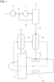
FIG. 1 is a schematic block diagram of a system for feeding fuel to an engine of an aircraft according to an embodiment. -
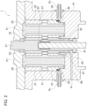
FIG. 2 is a sectional plan view of a triple gear pump according to the embodiment. -
FIG. 3 is a schematic cross-sectional view of the triple gear pump. -
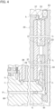
FIG. 4 is a sectional plan view mainly showing a floating bearing and its surroundings in the triple gear pump in an enlarged view. -
FIG. 5 is schematic block diagrams describing a series mode, a parallel mode and an unloaded mode. - Certain embodiments will be described hereinafter with reference to the appended drawings. Throughout the following description and the appended claims, the terms "axial direction" and "around the axis" are defined and used with respect to each shaft.
- Referring to
FIG. 1 , atriple gear pump 1 according to the present embodiment is to be incorporated in a system for feeding fuel to anengine 10 of an airplane and then pressurizes and expels fluid such as oil with relatively low viscosity, namely kerosine for example. - The fluid is supplied from a tank through a flow path F1 and is pressurized and expelled by the
triple gear pump 1. For the purpose of starting the system or any other purpose, another low-pressure pump 3 may be interposed on the flow path F1. To the low-pressure pump 3 applied is, but not limited to, a centrifugal pump. - As a power source for the
triple gear pump 1, energy extracted from a turbine of theengine 10 for example is applicable, and thus the amount of expelled fluid from thetriple gear pump 1 is proportional to, or at least depends on, the rotating speed of the turbine. As sometimes the rotating speed is relatively high whereas the fuel consumption is relatively small particularly when the airplane cruises at a high altitude for example, the amount of expelled fluid does not necessarily meet the demand byengine 10. The expelled fluid, in the amount beyond the demand, is portioned out and fed back through a return path F3 to the flow path F1 so that the fluid only at the demanded amount is fed to theengine 10. - As lubricant oil L is circulated and heated in the
engine 10, the expelled fluid is used for cooling it as well. Specifically, a flow path F5 is in fluid communication with an oil cooler 9, and the fluid cools the lubricant oil L and in response receives heat, and thereafter the fluid is introduced through a feeding path F7 to acombustion chamber 7 of theengine 10, thereby serving for combustion. - The
triple gear pump 1 by itself generates heat, and some part of the heat turns back through the return path F3 to thetriple gear pump 1, and resultantly non-negligible temperature rise may occur in fluid in the flow path F5. Therefore a cooling capacity of the oil cooler 9 sometimes loses balance against rise in temperature of the lubricant oil L. An air-cooling oil cooler 11 by air A extracted from a bypass flow path or such of theengine 10 is thus used supplementally. With increase in a load on the air-cooling oil cooler 11, which is caused by increase of return flow through the return path F3 and resultant rise in temperature of the expelled fluid, thermal stress on respective portions of the system will increase and some thermal energy will be exhausted in vain, thereby reducing energy efficiency. In a conventional triple gear pump, by enabling both a series mode and a parallel mode, increase and decrease of the amount of expelled fluid is enabled to minimize the amount of return flow. - The
triple gear pump 1 according to the present embodiment, by enabling an unloaded mode as well as the series and parallel modes, enables further increase and decrease of the amount of expelled fluid and also enables improvement of energy efficiency. Specifically, thetriple gear pump 1 enables a change from the series and parallel modes when the airplane idles on the ground and when it cruises at a high altitude for example, to a mode in which thetriple gear pump 1 is released from load and then the fuel is mainly fed by thecentrifugal pump 3 for example when it requires a great amount of fuel at a time of takeoff or such. The problem is difficulty in pressure control because high pressure should act on thetriple gear pump 1 throughout in the unloaded mode. Its solution will become apparent in the following descriptions. - Referring mainly to
FIG. 3 in combination withFIGs. 2 ,3 , thetriple gear pump 1 is generally provided with adrive gear 23 driven by adrive shaft 21 and first andsecond idler gears drive gear 23, where the combination of thedrive gear 23 and thefirst idler gear 27 constitutes a first gear pump G1 and the combination of thedrive gear 23 and thesecond idler gear 31 constitutes a second gear pump G2. Thehousing 41 encloses these elements andrespective spaces housing 41, as being in close contact with tooth tops of these gears, serve to pressurize and transport fluid in accordance with gear rotation. Thehousing 41 is provided with asuction port 49 and adischarge port 51 both in fluid communication with the first gear pump G1, and further provided with asuction port 53 and adischarge port 55 both in fluid communication with the second gear pump G2. When thedrive gear 23 is driven by an external power source to rotate about its axis, the first and second gear pumps G1 and G2 are set in operation in parallel so that fluid at a pressure P1 is sucked through thesuction port 49 is expelled under a pressure P3 through thedischarge port 51, and fluid at a pressure P5 is sucked through thesuction port 53 is expelled under a pressure P7 through thedischarge port 55. The discharge pressures P3, P7 are usually higher than the suction pressures P1, P5, whereas these pressures depend on operation modes as described below. - Referring mainly to
FIG. 2 , thedrive shaft 21 for coupling with the power source is led out of thehousing 41 whileshafts second idler gears housing 41. Theseshafts floating bearings floating bearings gears floating bearings gears - Gaps are held respectively between both ends of the first and
second idler shaft floating bearings housing 41 and are respectively in fluid communication with thesuction ports floating bearings second idler gears second idler shafts floating bearings 33 of thedrive shaft 21, acommunication path 67 is interposed and establishes fluid communication between thefloating bearings 37 and thefloating bearings 33. - To introduce an external pressure P9 distinct from suction pressures P1, P5 and apply it to the
floating bearings housing 41 for example. To receive the pressure P9, thefloating bearings discharge port 51 or thedischarge port 55 for example and then the pressure P9 applied to the step faces in principle matches with the discharge pressure P3 or P7. To further regulate applied pressure, any pressurizing means such assprings 39 may be interposed between the shoulders and thehousing 41. These are used for regulating pressures applied to thefloating bearings - Between the
housing 41 and thedrive shaft 21,seals seals aforementioned communication path 67 and theseal 61 interposed is aseal 65 for preventing transmission of fluid pressure. To thisseal 65, a labyrinth seal is applicable for example. - The
housing 41 may be further provided with anotherintroduction path 69 in order to retrieve fluid leaked out through the labyrinth seal and apply a proper pressure P11 to themechanical seal 61. Theintroduction path 69 may be connected to the flow path F1 for example so that the fluid before being given the pressure by thetriple gear pump 1 can apply its original pressure tomechanical seal 61. Of course, instead any other proper flow path may be connected thereto. - Referring to
FIG. 4 in combination withFIG. 2 , a force f1 originated from the suction pressure P5 acts on the upper ends of the upper floatingbearings bearings drive gear 23 and thesecond idler gear 31. The force originated from the suction pressure P5 also acts on the lower floatingbearing 37 and further on the lower floatingbearing 33 as thecommunication path 67 mediates so that an up force fu presses the lower floatingbearings drive gear 23 and thesecond idler gear 31. Because the common pressure acts thereon, the forces fd, fu are mutually in balance, thereby supporting thedrive gear 23 and thesecond idler gear 31 stably. Further, by using a force f2 distinct therefrom (normally greater), the up force fu can be regulated, thereby preventing the floatingbearing 37 from departing from thesecond idler gear 31. - While the aforementioned descriptions mainly relates to the second gear pump G2, a balance among forces is similarly established in regard to the first gear pump G1.
- The
triple gear pump 1 shall be put in operation if connected to a fuel feeder system as shown inFIG. 5 . Specifically, the flow path F1 branches off into two paths respectively connected to an inflow path F11 and an inflow path F17. Between the flow path F1 and the inflow path F11, a check or non-return valve V1 may be interposed. The inflow paths F11, F17 are respectively connected to thesuction ports discharge ports - Referring to
FIG. 5(a) in combination withFIGs. 2 through 4 , when the valve V3 is closed, thetriple gear pump 1 is in operation in a series mode. Then a relatively low pressure through the flow path F1 is applied to both the inflow path F11 in communication with thesuction port 49 of the first gear pump G1 and the inflow path F17 in communication with thesuction port 53 of the second gear pump G2. As the pressures P1, P5 are both low then, the down and up forces fd, fu are mutually in balance on any of the floatingbearings discharge port 51 flows through the flow paths F13, F15 and the fluid expelled out of thedischarge port 55 flows through the flow path F19, and then the fluid merges together in the flow path F21 and is then fed to theengine 10. - Referring to
FIG. 5(b) in place ofFIG. 5(a) , when the valve V3 is opened, thetriple gear pump 1 is in operation in a parallel mode. The exit pressure P3 of the first gear pump G1 acts on the inflow path F11 through the valve V3, and resultantly the suction pressure P1 rises to match with the exit pressure P3. If the check valve V1 is interposed there, the fluid is prevented from flowing backward toward the flow path F1. Even then the pressure P1 commonly acts on both the floatingbearings 35, thereby balancing the down and up forces fd, fu with each other. Any change in the pressure P1 does not affect the floatingbearings - To the valve V3, not a switching valve but a regulating valve such as a variable throttle valve is also applicable, which can continuously regulate the flow rate. In this case, while the valve V3 can be set in medium states as well as the totally closed state (shown in
FIG. 5(a) ) and the totally opened state (shown inFIG. 5(b) ), force balances on the floatingbearings - Referring to
FIG. 5(c) in place ofFIG. 5(a) and FIG. 5(b) , the present embodiment enables the unloaded mode. The valve V3 is then kept open (or may be closed) and the amount of expelled fluid from thecentrifugal pump 3 is increased. Then high-pressure made by thecentrifugal pump 3 is applied to both the gear pumps G1, G2. As will be understood from the above descriptions, the down and up forces fd, fu are mutually in balance on the floatingbearing 33, let alone the floatingbearings bearing 33 of thedrive shaft 21 through thecommunication path 67. Despite high-pressure application to the floatingbearing 33, thelabyrinth seal 65 bars the pressure from acting on themechanical seal 61. Fluid leakage through themechanical seal 61 does not occur, or smooth operation of themechanical seal 61 is not spoiled. - In the unloaded mode, both the gear pumps G1, G2 do no work substantially and mainly the
centrifugal pump 3 alone contributes to feeding the fluid. The centrifugal pump can, particularly when theengine 10 outputs high power, efficiently expel a great amount of fluid. As being understood with reference again toFIG. 1 , as thetriple gear pump 1 does substantially no work and the return flow through the return path F3 can be minimized, temperature rise of the fluid fed to the flow path F5 can be suppressed. The cooling capacity of the oil cooler 9 can be sufficiently utilized and in turn the load on theoil cooler 11 can be suppressed. - The present embodiment allows selection of an optimum mode in response to a state of the airplane, for example selecting the parallel mode when the
engine 10 rotates at relatively low speed but high power is required, selecting the series mode when the airplane cruises at a high altitude, and selecting the unloaded mode to mainly use the centrifugal pump when a particularly high power is required at a time of takeoff. The present embodiment can realize high energy efficiency in any of these modes. - Although certain embodiments have been described above, modifications and variations of the embodiments described above will occur to those skilled in the art, in light of the above teachings.
- The disclosed art provides a triple gear pump that is capable of being stably operative not only in a series or parallel mode but also in an unloaded mode.
Claims (5)
- A triple gear pump with a drive gear and first and second idler gear respectively in mesh with the drive gear so as to respectively constitute first and second gear pumps for expelling fluid used as a fuel, comprising:a housing enclosing the first gear pump and the second gear pump;a drive shaft linked to the drive gear so as to rotate unitarily with the drive gear and led out of the housing;a drive-shaft bearing rotatably supporting the drive shaft and being axially floatingly movable, the drive-shaft bearing receiving pressure applied by the fluid so as to come in contact with the drive gear;a mechanical seal interposed between the drive shaft and the housing to prevent the fluid from leaking out of the housing; anda seal interposed between the drive-shaft bearing and the mechanical seal to prevent the pressure of the fluid from being transmitted to the mechanical seal.
- The triple gear pump of claim 1, further comprising:an idler shaft linked to the second idler gear;a floating bearing rotatably supporting the idler shaft and being axially floatingly movable to axially come in contact with the second idler gear; anda communication path establishing fluid communication within the housing between the drive-shaft bearing and the floating bearing,wherein the seal is interposed between the communication path and the mechanical seal.
- The triple gear pump of claim 2, further comprising:a suction port opened in the housing and holding fluid communication with the second gear pump so as to introduce the fluid into the second gear pump,wherein the suction port is in fluid communication with the drive-shaft bearing, the floating bearing and the communication path so as to apply the pressure to drive-shaft bearing and the floating bearing.
- The triple gear pump of claim 1, further comprising:
an introduction path configured to introduce the fluid before being given the pressure from an outside of the housing. - The triple gear pump of any of claims 1 through 4, wherein the seal comprises a labyrinth seal.
Applications Claiming Priority (1)
| Application Number | Priority Date | Filing Date | Title |
|---|---|---|---|
| PCT/JP2022/029919 WO2024029027A1 (en) | 2022-08-04 | 2022-08-04 | Triple gear pump |
Publications (2)
| Publication Number | Publication Date |
|---|---|
| EP4567277A1 true EP4567277A1 (en) | 2025-06-11 |
| EP4567277A4 EP4567277A4 (en) | 2026-04-22 |
Family
ID=89848932
Family Applications (1)
| Application Number | Title | Priority Date | Filing Date |
|---|---|---|---|
| EP22954016.6A Pending EP4567277A4 (en) | 2022-08-04 | 2022-08-04 | Triple-gear pump |
Country Status (2)
| Country | Link |
|---|---|
| EP (1) | EP4567277A4 (en) |
| WO (1) | WO2024029027A1 (en) |
Family Cites Families (10)
| Publication number | Priority date | Publication date | Assignee | Title |
|---|---|---|---|---|
| JP2636493B2 (en) * | 1990-10-29 | 1997-07-30 | 株式会社島津製作所 | Fluid machinery |
| JPH09144668A (en) * | 1995-11-27 | 1997-06-03 | Shimadzu Corp | Gear pump |
| EP0881392B1 (en) * | 1998-07-31 | 2007-03-28 | Maag Pump Systems Textron AG | Arrangement for sealing a shaft passage in gear pumps |
| JP2000087872A (en) * | 1998-09-08 | 2000-03-28 | Shimadzu Corp | Gear pump for highly viscous fluid |
| JP5040214B2 (en) | 2006-08-23 | 2012-10-03 | 株式会社Ihi | Triple gear pump |
| JP5983419B2 (en) * | 2013-01-18 | 2016-08-31 | 株式会社Ihi | Fuel system |
| JP6265008B2 (en) * | 2014-03-31 | 2018-01-24 | 株式会社Ihi | Triple gear pump and fluid supply device |
| WO2017009994A1 (en) * | 2015-07-16 | 2017-01-19 | 株式会社Ihi | Triple gear pump and fluid supplying device |
| WO2020250796A1 (en) * | 2019-06-11 | 2020-12-17 | 株式会社Ihi | Pump system |
| JP7571603B2 (en) * | 2021-02-17 | 2024-10-23 | 株式会社Ihi | Triple gear pump |
-
2022
- 2022-08-04 EP EP22954016.6A patent/EP4567277A4/en active Pending
- 2022-08-04 WO PCT/JP2022/029919 patent/WO2024029027A1/en not_active Ceased
Also Published As
| Publication number | Publication date |
|---|---|
| EP4567277A4 (en) | 2026-04-22 |
| WO2024029027A1 (en) | 2024-02-08 |
Similar Documents
| Publication | Publication Date | Title |
|---|---|---|
| US8172512B2 (en) | Accessory gearbox system with compressor driven seal air supply | |
| US10138816B2 (en) | Fuel pumping unit | |
| US4245465A (en) | Gas turbine engine lubrication system including three stage flow control valve | |
| CN101523053B (en) | Three-throw gear pump | |
| US7426834B2 (en) | “Get home” oil supply and scavenge system | |
| US20150330401A1 (en) | Centrifugal steam compressor and shaft seal system used with same | |
| US5894825A (en) | Engine lubrication system | |
| US20170058895A1 (en) | Dual pump system for automatic transmission augmentation, extended stop and start, and sailing | |
| US9046002B2 (en) | Oil supply system for an aircraft engine | |
| US7094042B1 (en) | Dual-inlet gear pump with unequal flow capability | |
| KR20190045924A (en) | Dual input pumps and systems | |
| US10677095B2 (en) | Lubrication device for a turbine engine | |
| US20050232784A1 (en) | Pump assembly | |
| US3635602A (en) | Lifting tip seal pump | |
| CN116368291A (en) | Turbine lubrication system including bypass for preferential supply of lubricant to low speed reduction gears | |
| US5215430A (en) | Ignition-source free fuel pump | |
| US11965510B2 (en) | Compressor body and compressor to supply liquid into working chambers and whose downstream portion reaches a suction bearing chamber | |
| US9546728B2 (en) | Balanced binary pump for CVT transmission | |
| JP7571603B2 (en) | Triple gear pump | |
| JP4065721B2 (en) | Double gear pump and switching circuit for serial / parallel switching | |
| EP0657651A1 (en) | Pump | |
| US20140356195A1 (en) | Oil suction device of vehicle | |
| WO2024029027A1 (en) | Triple gear pump | |
| US20050191186A1 (en) | Aeronautical generator | |
| EP3249221B1 (en) | Axial piston pump/motor |
Legal Events
| Date | Code | Title | Description |
|---|---|---|---|
| STAA | Information on the status of an ep patent application or granted ep patent |
Free format text: STATUS: THE INTERNATIONAL PUBLICATION HAS BEEN MADE |
|
| PUAI | Public reference made under article 153(3) epc to a published international application that has entered the european phase |
Free format text: ORIGINAL CODE: 0009012 |
|
| STAA | Information on the status of an ep patent application or granted ep patent |
Free format text: STATUS: REQUEST FOR EXAMINATION WAS MADE |
|
| 17P | Request for examination filed |
Effective date: 20250304 |
|
| AK | Designated contracting states |
Kind code of ref document: A1 Designated state(s): AL AT BE BG CH CY CZ DE DK EE ES FI FR GB GR HR HU IE IS IT LI LT LU LV MC MK MT NL NO PL PT RO RS SE SI SK SM TR |
|
| DAV | Request for validation of the european patent (deleted) | ||
| DAX | Request for extension of the european patent (deleted) | ||
| REG | Reference to a national code |
Ref country code: DE Ref legal event code: R079 Free format text: PREVIOUS MAIN CLASS: F04C0011000000 Ipc: F04C0002140000 |
|
| A4 | Supplementary search report drawn up and despatched |
Effective date: 20260323 |
|
| RIC1 | Information provided on ipc code assigned before grant |
Ipc: F04C 2/14 20060101AFI20260317BHEP Ipc: F04C 14/02 20060101ALI20260317BHEP Ipc: F04C 14/06 20060101ALI20260317BHEP Ipc: F04C 15/00 20060101ALI20260317BHEP |