EP4567256A1 - Sealing system for a steam turbine - Google Patents
Sealing system for a steam turbine Download PDFInfo
- Publication number
- EP4567256A1 EP4567256A1 EP23213899.0A EP23213899A EP4567256A1 EP 4567256 A1 EP4567256 A1 EP 4567256A1 EP 23213899 A EP23213899 A EP 23213899A EP 4567256 A1 EP4567256 A1 EP 4567256A1
- Authority
- EP
- European Patent Office
- Prior art keywords
- grooves
- sealing
- steam
- seal
- rotor
- Prior art date
- Legal status (The legal status is an assumption and is not a legal conclusion. Google has not performed a legal analysis and makes no representation as to the accuracy of the status listed.)
- Withdrawn
Links
Images
Classifications
-
- F—MECHANICAL ENGINEERING; LIGHTING; HEATING; WEAPONS; BLASTING
- F01—MACHINES OR ENGINES IN GENERAL; ENGINE PLANTS IN GENERAL; STEAM ENGINES
- F01D—NON-POSITIVE DISPLACEMENT MACHINES OR ENGINES, e.g. STEAM TURBINES
- F01D11/00—Preventing or minimising internal leakage of working-fluid, e.g. between stages
- F01D11/02—Preventing or minimising internal leakage of working-fluid, e.g. between stages by non-contact sealings, e.g. of labyrinth type
-
- F—MECHANICAL ENGINEERING; LIGHTING; HEATING; WEAPONS; BLASTING
- F01—MACHINES OR ENGINES IN GENERAL; ENGINE PLANTS IN GENERAL; STEAM ENGINES
- F01D—NON-POSITIVE DISPLACEMENT MACHINES OR ENGINES, e.g. STEAM TURBINES
- F01D25/00—Component parts, details, or accessories, not provided for in, or of interest apart from, other groups
- F01D25/32—Collecting of condensation water; Drainage ; Removing solid particles
-
- F—MECHANICAL ENGINEERING; LIGHTING; HEATING; WEAPONS; BLASTING
- F16—ENGINEERING ELEMENTS AND UNITS; GENERAL MEASURES FOR PRODUCING AND MAINTAINING EFFECTIVE FUNCTIONING OF MACHINES OR INSTALLATIONS; THERMAL INSULATION IN GENERAL
- F16J—PISTONS; CYLINDERS; SEALINGS
- F16J15/00—Sealings
- F16J15/002—Sealings comprising at least two sealings in succession
- F16J15/004—Sealings comprising at least two sealings in succession forming of recuperation chamber for the leaking fluid
-
- F—MECHANICAL ENGINEERING; LIGHTING; HEATING; WEAPONS; BLASTING
- F16—ENGINEERING ELEMENTS AND UNITS; GENERAL MEASURES FOR PRODUCING AND MAINTAINING EFFECTIVE FUNCTIONING OF MACHINES OR INSTALLATIONS; THERMAL INSULATION IN GENERAL
- F16J—PISTONS; CYLINDERS; SEALINGS
- F16J15/00—Sealings
- F16J15/44—Free-space packings
- F16J15/447—Labyrinth packings
- F16J15/4472—Labyrinth packings with axial path
-
- F—MECHANICAL ENGINEERING; LIGHTING; HEATING; WEAPONS; BLASTING
- F05—INDEXING SCHEMES RELATING TO ENGINES OR PUMPS IN VARIOUS SUBCLASSES OF CLASSES F01-F04
- F05D—INDEXING SCHEME FOR ASPECTS RELATING TO NON-POSITIVE-DISPLACEMENT MACHINES OR ENGINES, GAS-TURBINES OR JET-PROPULSION PLANTS
- F05D2220/00—Application
- F05D2220/30—Application in turbines
- F05D2220/31—Application in turbines in steam turbines
-
- F—MECHANICAL ENGINEERING; LIGHTING; HEATING; WEAPONS; BLASTING
- F05—INDEXING SCHEMES RELATING TO ENGINES OR PUMPS IN VARIOUS SUBCLASSES OF CLASSES F01-F04
- F05D—INDEXING SCHEME FOR ASPECTS RELATING TO NON-POSITIVE-DISPLACEMENT MACHINES OR ENGINES, GAS-TURBINES OR JET-PROPULSION PLANTS
- F05D2240/00—Components
- F05D2240/55—Seals
-
- F—MECHANICAL ENGINEERING; LIGHTING; HEATING; WEAPONS; BLASTING
- F05—INDEXING SCHEMES RELATING TO ENGINES OR PUMPS IN VARIOUS SUBCLASSES OF CLASSES F01-F04
- F05D—INDEXING SCHEME FOR ASPECTS RELATING TO NON-POSITIVE-DISPLACEMENT MACHINES OR ENGINES, GAS-TURBINES OR JET-PROPULSION PLANTS
- F05D2260/00—Function
- F05D2260/60—Fluid transfer
- F05D2260/602—Drainage
-
- F—MECHANICAL ENGINEERING; LIGHTING; HEATING; WEAPONS; BLASTING
- F05—INDEXING SCHEMES RELATING TO ENGINES OR PUMPS IN VARIOUS SUBCLASSES OF CLASSES F01-F04
- F05D—INDEXING SCHEME FOR ASPECTS RELATING TO NON-POSITIVE-DISPLACEMENT MACHINES OR ENGINES, GAS-TURBINES OR JET-PROPULSION PLANTS
- F05D2260/00—Function
- F05D2260/60—Fluid transfer
- F05D2260/602—Drainage
- F05D2260/6022—Drainage of leakage having past a seal
Definitions
- Subject of the invention is a sealing system for backpressure steam turbines, consisting of at least one labyrinth seal, according top of the independent claim 1.
- a labyrinth seal is a type of mechanical seal used to prevent the leakage of fluids or gases between two components, typically in rotating machinery such as pumps, compressors, or turbines. It consists of a series of specially designed grooves or channels that create a tortuous path for the fluid or gas to pass through.
- the basic principle behind a labyrinth seal is to create multiple barriers or obstacles that the fluid or gas must navigate through, which significantly reduces the pressure differential and minimizes the leakage.
- the labyrinth seal takes advantage of the viscous drag and turbulence generated by the rotating components to impede the flow of the fluid or gas.
- the seal consists of a stationary component (stator) and a rotating component (rotor).
- the stator contains the grooves or channels, while the rotor has corresponding features that interlock with the stator.
- the grooves on the stator and rotor are designed in a complex pattern, creating a maze-like structure.
- the fluid or gas must pass through these narrow gaps and negotiate a series of twists and turns.
- the clearance gaps between the rotor and stator are deliberately small but allow for minimal axial movement. This ensures that the fluid or gas must travel through the labyrinthine path rather than bypassing it. As the fluid or gas enters the first groove, it encounters resistance due to the narrow clearance. This friction causes energy loss and generates turbulence, which further impedes the flow.
- the fluid or gas then encounters subsequent grooves, each designed to create additional barriers and turbulence, further reducing the pressure differential and leakage potential.
- the pressure differential has decreased significantly.
- the seal design aims to achieve pressure equalization between the high-pressure and low-pressure sides, preventing leakage across the seal.
- Labyrinth seals are effective in sealing applications because they rely on the complex geometry and tortuous path to impede the flow of fluid or gas. They are commonly used in applications where traditional seals, such as O-rings or gaskets, may not be suitable due to high speeds, high temperatures, or aggressive environments.
- the turbine deals inside with wet steam the liquid phase precipitating from the steam is due to the inertia effects including gravity separated from the main steam flow and has tendency to fill various grooves of the sealing system.
- retractable labyrinth seal segments filled grooves of the labyrinth segments can block the segment parts to move in case of the rotor comes to the contact with segment part. Since the rotor movement is high frequency movement the water filling the grooves down the labyrinth segments is not able to move away inside the groove as fast as necessary and increases stiffness of the rotor - sealing system. That might lead to the retuning the turbine critical speed (spectrum of natural frequencies) due to the high impedance of retractable labyrinth segments in case of rotor to sealing contact. Externally such situation can appear as high turbine vibration.
- the task of the invention is to overcome the disadvantages of existing labyrinth seals.
- the inventive sealing system for a backpressure steam turbine consisting of at least one labyrinth seal, the labyrinth seal comprising at least one seal housing with a couple of grooves and a rotor with a couple of sealing tips, whereby the sealing tips engaging in the grooves is characterized in that, the sealing house contains a drainage system with allows water (liquid) in the grooves, to dissipate.
- a first embodiment of the invention provides that the drainage system is configured in that way, that liquid is carried away from the grooves by gravity.
- the drainage system comprising, at a minimum, one drain hole, preferably in each groove, which is arranged at the lowest point of the grooves. This ensures that the liquid can be drained off from the grooves completely.
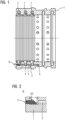
- Fig. 1 shows an axial view of a sealing housing 1 for an inventive sealing system for a steam turbine.
- the sealing system consisting of at least one labyrinth seal, the labyrinth seal comprising of the seal housing 1 with a couple of grooves 2 and a rotor with a couple of sealing tips, whereby the sealing tips engaging in the grooves 2.
- fig. 1 shows only the seal housing 1 without the rotor.
- the sealing house 1 contains a drainage system 3 with allows liquid in the grooves 2, to dissipate.
- the drainage system 3 is configured in that way, that liquid is carried away from the grooves 2 by gravity.
- the drainage system 3 comprising, drain holes 4 in each groove 2, which is arranged at the lowest point of the grooves 2.
- Fig. 2 shows detail B in fig. 1 .
- the axially drainpipe 5 could be build by a blind hole in the sealing house 1, wherein the open end of the blind hole is closed by a closing plug 7.
- the exit 6 is built by a radial hole in the sealing house 1 as shown in Fig. 1 .
Landscapes
- Engineering & Computer Science (AREA)
- General Engineering & Computer Science (AREA)
- Mechanical Engineering (AREA)
- Sealing Using Fluids, Sealing Without Contact, And Removal Of Oil (AREA)
Abstract
The invention concerns a sealing system for a steam turbine, consisting of at least one labyrinth seal, the labyrinth seal comprising at least one seal housing (1) with a couple of grooves (2) and a rotor with a couple of sealing tips, wherein the sealing tips engages in the grooves (2). The sealing house (1) contains a drainage system (3) with allows liquid in the grooves (2) to dissipate.
Description
- Subject of the invention is a sealing system for backpressure steam turbines, consisting of at least one labyrinth seal, according top of the independent claim 1.
- A labyrinth seal is a type of mechanical seal used to prevent the leakage of fluids or gases between two components, typically in rotating machinery such as pumps, compressors, or turbines. It consists of a series of specially designed grooves or channels that create a tortuous path for the fluid or gas to pass through. The basic principle behind a labyrinth seal is to create multiple barriers or obstacles that the fluid or gas must navigate through, which significantly reduces the pressure differential and minimizes the leakage. The labyrinth seal takes advantage of the viscous drag and turbulence generated by the rotating components to impede the flow of the fluid or gas.
- The seal consists of a stationary component (stator) and a rotating component (rotor). The stator contains the grooves or channels, while the rotor has corresponding features that interlock with the stator. The grooves on the stator and rotor are designed in a complex pattern, creating a maze-like structure. The fluid or gas must pass through these narrow gaps and negotiate a series of twists and turns. The clearance gaps between the rotor and stator are deliberately small but allow for minimal axial movement. This ensures that the fluid or gas must travel through the labyrinthine path rather than bypassing it. As the fluid or gas enters the first groove, it encounters resistance due to the narrow clearance. This friction causes energy loss and generates turbulence, which further impedes the flow. The fluid or gas then encounters subsequent grooves, each designed to create additional barriers and turbulence, further reducing the pressure differential and leakage potential. By the time the fluid or gas reaches the end of the labyrinth path, the pressure differential has decreased significantly. The seal design aims to achieve pressure equalization between the high-pressure and low-pressure sides, preventing leakage across the seal.
- Labyrinth seals are effective in sealing applications because they rely on the complex geometry and tortuous path to impede the flow of fluid or gas. They are commonly used in applications where traditional seals, such as O-rings or gaskets, may not be suitable due to high speeds, high temperatures, or aggressive environments.
- If steam turbines operate with wet steam it can leads to a malfunction of the steam turbine steam labyrinth sealings, because there is a risk that the inner cavities of the steam sealing are flooding with liquid phase of the steam. That situation can occur in case of the steam sealing of the backpressure steam turbine dealing with wet steam at the exhaust or steam turbine dealing with wet steam at the inlet, in the inner parts and exhaust section too. The point is that backpressure steam sealing system does not use external steam buffering system so that the steam flow in the backpressure turbine inside of its steam seals is from the turbine inner pressurized space to the outer turbine space. If the turbine deals inside with wet steam the liquid phase precipitating from the steam is due to the inertia effects including gravity separated from the main steam flow and has tendency to fill various grooves of the sealing system. In case of retractable labyrinth seal segments filled grooves of the labyrinth segments can block the segment parts to move in case of the rotor comes to the contact with segment part. Since the rotor movement is high frequency movement the water filling the grooves down the labyrinth segments is not able to move away inside the groove as fast as necessary and increases stiffness of the rotor - sealing system. That might lead to the retuning the turbine critical speed (spectrum of natural frequencies) due to the high impedance of retractable labyrinth segments in case of rotor to sealing contact. Externally such situation can appear as high turbine vibration.
- The task of the invention is to overcome the disadvantages of existing labyrinth seals.
- The task is solved by the features of the independent patent claim 1. Further advantages of the invention which can be used individually or in combination are the subject of the subclaims.
- The inventive sealing system for a backpressure steam turbine, consisting of at least one labyrinth seal, the labyrinth seal comprising at least one seal housing with a couple of grooves and a rotor with a couple of sealing tips, whereby the sealing tips engaging in the grooves is characterized in that, the sealing house contains a drainage system with allows water (liquid) in the grooves, to dissipate.
- If the liquid is taken out of the grooves of the labyrinth segments, then there is no blocking effect against the segment moving.
- A first embodiment of the invention provides that the drainage system is configured in that way, that liquid is carried away from the grooves by gravity.
- Such an embodiment is simple, cheap, and low susceptibility to interference.
- According to a further embodiment of the invention the drainage system comprising, at a minimum, one drain hole, preferably in each groove, which is arranged at the lowest point of the grooves. This ensures that the liquid can be drained off from the grooves completely.
- Further embodiments and advantage of the invention will be described in the following on the drawings. It shows:
- Fig. 1:
- an axial view of a sealing housing for an inventive sealing system;
- Fig.2:
- a detail view of
detail 3 fromfigure 1 . - The figures show only the basic structure of the invention, which contains only the features necessary to describe the invention. Identical or functionally identical parts are designated with the same reference signs in both figures.
-
Fig. 1 shows an axial view of a sealing housing 1 for an inventive sealing system for a steam turbine. The sealing system consisting of at least one labyrinth seal, the labyrinth seal comprising of the seal housing 1 with a couple ofgrooves 2 and a rotor with a couple of sealing tips, whereby the sealing tips engaging in thegrooves 2. For a better understanding of the inventionfig. 1 shows only the seal housing 1 without the rotor. The sealing house 1 contains adrainage system 3 with allows liquid in thegrooves 2, to dissipate. Thedrainage system 3 is configured in that way, that liquid is carried away from thegrooves 2 by gravity. For this, thedrainage system 3 comprising, drainholes 4 in eachgroove 2, which is arranged at the lowest point of thegrooves 2. If liquid enters thegrooves 2, the liquid is flowing due to the gravity, to the lowest point of thegrooves 2. From there the liquid flows through the, at the lowest point of thegrooves 2, essentially radially arrangeddrain holes 4 and an essentially axiallydrainpipe 5, which is connect with thedrain holes 4 and formed in the sealing housing 1 to an exit 6. Thedraining system 3 is very easily build by radial and axial holes. -
Fig. 2 shows detail B infig. 1 . As shown infig. 2 theaxially drainpipe 5 could be build by a blind hole in the sealing house 1, wherein the open end of the blind hole is closed by aclosing plug 7. For draining the liquid out of the sealing housing 1 the exit 6 is built by a radial hole in the sealing house 1 as shown inFig. 1 .
Claims (3)
- Sealing system for a steam turbine, consisting of at least one labyrinth seal, the labyrinth seal comprising at least one seal housing (1) with a couple of grooves (2) and a rotor with a couple of sealing tips, whereby the sealing tips engaging in the grooves (2)
characterized in that,
the sealing house (1) contains a drainage system (3) with allows liquid in the grooves (2), to dissipate. - Sealing system according claim 1,
characterized in that,
the drainage system (3) is configured in that way, that liquid is carried away from the grooves (2) by gravity. - Sealing system according claim 1 or 2,
characterized in that,
the drainage system (3) comprising, at a minimum, one drain hole (4) in each groove (2), which is arranged at the lowest point of the grooves (2).
Priority Applications (1)
| Application Number | Priority Date | Filing Date | Title |
|---|---|---|---|
| EP23213899.0A EP4567256A1 (en) | 2023-12-04 | 2023-12-04 | Sealing system for a steam turbine |
Applications Claiming Priority (1)
| Application Number | Priority Date | Filing Date | Title |
|---|---|---|---|
| EP23213899.0A EP4567256A1 (en) | 2023-12-04 | 2023-12-04 | Sealing system for a steam turbine |
Publications (1)
| Publication Number | Publication Date |
|---|---|
| EP4567256A1 true EP4567256A1 (en) | 2025-06-11 |
Family
ID=89076331
Family Applications (1)
| Application Number | Title | Priority Date | Filing Date |
|---|---|---|---|
| EP23213899.0A Withdrawn EP4567256A1 (en) | 2023-12-04 | 2023-12-04 | Sealing system for a steam turbine |
Country Status (1)
| Country | Link |
|---|---|
| EP (1) | EP4567256A1 (en) |
Cited By (1)
| Publication number | Priority date | Publication date | Assignee | Title |
|---|---|---|---|---|
| CN120984923A (en) * | 2025-10-24 | 2025-11-21 | 冈田精机(常州)有限公司 | A high-speed electric spindle structure |
Citations (3)
| Publication number | Priority date | Publication date | Assignee | Title |
|---|---|---|---|---|
| US20110272893A1 (en) * | 2010-05-07 | 2011-11-10 | Man Diesel & Turbo Se | Labyrinth Seal For A Turbomachine |
| US20200238384A1 (en) * | 2017-09-18 | 2020-07-30 | Siemens Aktiengesellschaft | Sealing ring |
| DE102019218883A1 (en) * | 2019-12-04 | 2021-06-10 | Siemens Aktiengesellschaft | Shaft sealing ring, machine with such a shaft sealing ring and method for operating a machine |
-
2023
- 2023-12-04 EP EP23213899.0A patent/EP4567256A1/en not_active Withdrawn
Patent Citations (3)
| Publication number | Priority date | Publication date | Assignee | Title |
|---|---|---|---|---|
| US20110272893A1 (en) * | 2010-05-07 | 2011-11-10 | Man Diesel & Turbo Se | Labyrinth Seal For A Turbomachine |
| US20200238384A1 (en) * | 2017-09-18 | 2020-07-30 | Siemens Aktiengesellschaft | Sealing ring |
| DE102019218883A1 (en) * | 2019-12-04 | 2021-06-10 | Siemens Aktiengesellschaft | Shaft sealing ring, machine with such a shaft sealing ring and method for operating a machine |
Cited By (1)
| Publication number | Priority date | Publication date | Assignee | Title |
|---|---|---|---|---|
| CN120984923A (en) * | 2025-10-24 | 2025-11-21 | 冈田精机(常州)有限公司 | A high-speed electric spindle structure |
Similar Documents
| Publication | Publication Date | Title |
|---|---|---|
| US5639095A (en) | Low-leakage and low-instability labyrinth seal | |
| US7445213B1 (en) | Stepped labyrinth seal | |
| RU2600195C2 (en) | Axial shaft seal | |
| US20090160135A1 (en) | Labyrinth seal with reduced leakage flow by grooves and teeth synergistic action | |
| EP2083200A1 (en) | Seal assembly | |
| US20170096905A1 (en) | Bi-directional shaft seal | |
| RU2662845C2 (en) | Suction pump with pitot tubes with the gear drive | |
| EP2894377B1 (en) | Turbo-engine | |
| US11739654B2 (en) | Abradable labyrinth seal for refrigerant compressors | |
| US12146501B2 (en) | Step seal for refrigerant compressors | |
| AU2013254625A1 (en) | High damping labyrinth seal with helicoidal or helicoidal-cylindrical mixed pattern | |
| KR101099829B1 (en) | Sealing assembly and vacuum pump | |
| CN105757257A (en) | Active labyrinth seal structure | |
| JP2017020412A (en) | Fluid machine and shaft seal device | |
| EP4158201B1 (en) | Compressor rotor having flow loop through tie bolt | |
| KR102579622B1 (en) | rotating machine | |
| WO2012001997A1 (en) | Seal device and fluid machinery provided with same | |
| US10253886B2 (en) | High temperature subsea dynamic seals | |
| CN204201100U (en) | A kind of assembly type revolution lip labyrinth gland | |
| EP3032149A1 (en) | Sealing device, rotating machine, and method for manufacturing sealing device | |
| RU2581328C2 (en) | Abradable seal for inner stator cover | |
| CN110645355B (en) | Flow guide type combined labyrinth sealing device | |
| CN113124168B (en) | Waterproof oil-separating sealing device | |
| RU2678865C2 (en) | Rotor, axial compressor, installation method | |
| CN104315150A (en) | Rotary lip labyrinth sealing device |
Legal Events
| Date | Code | Title | Description |
|---|---|---|---|
| PUAI | Public reference made under article 153(3) epc to a published international application that has entered the european phase |
Free format text: ORIGINAL CODE: 0009012 |
|
| STAA | Information on the status of an ep patent application or granted ep patent |
Free format text: STATUS: THE APPLICATION HAS BEEN PUBLISHED |
|
| AK | Designated contracting states |
Kind code of ref document: A1 Designated state(s): AL AT BE BG CH CY CZ DE DK EE ES FI FR GB GR HR HU IE IS IT LI LT LU LV MC ME MK MT NL NO PL PT RO RS SE SI SK SM TR |
|
| STAA | Information on the status of an ep patent application or granted ep patent |
Free format text: STATUS: THE APPLICATION IS DEEMED TO BE WITHDRAWN |
|
| 18D | Application deemed to be withdrawn |
Effective date: 20251212 |